WO2015098123A1 - 一軸アクチュエータ - Google Patents
一軸アクチュエータ Download PDFInfo
- Publication number
- WO2015098123A1 WO2015098123A1 PCT/JP2014/006500 JP2014006500W WO2015098123A1 WO 2015098123 A1 WO2015098123 A1 WO 2015098123A1 JP 2014006500 W JP2014006500 W JP 2014006500W WO 2015098123 A1 WO2015098123 A1 WO 2015098123A1
- Authority
- WO
- WIPO (PCT)
- Prior art keywords
- pulley
- motor
- side timing
- rotation transmission
- transmission shaft
- Prior art date
- Legal status (The legal status is an assumption and is not a legal conclusion. Google has not performed a legal analysis and makes no representation as to the accuracy of the status listed.)
- Ceased
Links
Images


Classifications
-
- F—MECHANICAL ENGINEERING; LIGHTING; HEATING; WEAPONS; BLASTING
- F16—ENGINEERING ELEMENTS AND UNITS; GENERAL MEASURES FOR PRODUCING AND MAINTAINING EFFECTIVE FUNCTIONING OF MACHINES OR INSTALLATIONS; THERMAL INSULATION IN GENERAL
- F16H—GEARING
- F16H19/00—Gearings comprising essentially only toothed gears or friction members and not capable of conveying indefinitely-continuing rotary motion
- F16H19/02—Gearings comprising essentially only toothed gears or friction members and not capable of conveying indefinitely-continuing rotary motion for interconverting rotary or oscillating motion and reciprocating motion
- F16H19/06—Gearings comprising essentially only toothed gears or friction members and not capable of conveying indefinitely-continuing rotary motion for interconverting rotary or oscillating motion and reciprocating motion comprising flexible members, e.g. an endless flexible member
- F16H19/0622—Gearings comprising essentially only toothed gears or friction members and not capable of conveying indefinitely-continuing rotary motion for interconverting rotary or oscillating motion and reciprocating motion comprising flexible members, e.g. an endless flexible member for converting reciprocating movement into oscillating movement and vice versa, the reciprocating movement is perpendicular to the axis of oscillation
-
- F—MECHANICAL ENGINEERING; LIGHTING; HEATING; WEAPONS; BLASTING
- F16—ENGINEERING ELEMENTS AND UNITS; GENERAL MEASURES FOR PRODUCING AND MAINTAINING EFFECTIVE FUNCTIONING OF MACHINES OR INSTALLATIONS; THERMAL INSULATION IN GENERAL
- F16H—GEARING
- F16H19/00—Gearings comprising essentially only toothed gears or friction members and not capable of conveying indefinitely-continuing rotary motion
- F16H19/02—Gearings comprising essentially only toothed gears or friction members and not capable of conveying indefinitely-continuing rotary motion for interconverting rotary or oscillating motion and reciprocating motion
- F16H19/06—Gearings comprising essentially only toothed gears or friction members and not capable of conveying indefinitely-continuing rotary motion for interconverting rotary or oscillating motion and reciprocating motion comprising flexible members, e.g. an endless flexible member
- F16H19/0672—Gearings comprising essentially only toothed gears or friction members and not capable of conveying indefinitely-continuing rotary motion for interconverting rotary or oscillating motion and reciprocating motion comprising flexible members, e.g. an endless flexible member characterised by means for tensioning the flexible member
-
- H—ELECTRICITY
- H02—GENERATION; CONVERSION OR DISTRIBUTION OF ELECTRIC POWER
- H02K—DYNAMO-ELECTRIC MACHINES
- H02K7/00—Arrangements for handling mechanical energy structurally associated with dynamo-electric machines, e.g. structural association with mechanical driving motors or auxiliary dynamo-electric machines
- H02K7/06—Means for converting reciprocating motion into rotary motion or vice versa
-
- F—MECHANICAL ENGINEERING; LIGHTING; HEATING; WEAPONS; BLASTING
- F16—ENGINEERING ELEMENTS AND UNITS; GENERAL MEASURES FOR PRODUCING AND MAINTAINING EFFECTIVE FUNCTIONING OF MACHINES OR INSTALLATIONS; THERMAL INSULATION IN GENERAL
- F16H—GEARING
- F16H19/00—Gearings comprising essentially only toothed gears or friction members and not capable of conveying indefinitely-continuing rotary motion
- F16H19/02—Gearings comprising essentially only toothed gears or friction members and not capable of conveying indefinitely-continuing rotary motion for interconverting rotary or oscillating motion and reciprocating motion
- F16H19/06—Gearings comprising essentially only toothed gears or friction members and not capable of conveying indefinitely-continuing rotary motion for interconverting rotary or oscillating motion and reciprocating motion comprising flexible members, e.g. an endless flexible member
- F16H2019/0681—Gearings comprising essentially only toothed gears or friction members and not capable of conveying indefinitely-continuing rotary motion for interconverting rotary or oscillating motion and reciprocating motion comprising flexible members, e.g. an endless flexible member the flexible member forming a closed loop
- F16H2019/0686—Gearings comprising essentially only toothed gears or friction members and not capable of conveying indefinitely-continuing rotary motion for interconverting rotary or oscillating motion and reciprocating motion comprising flexible members, e.g. an endless flexible member the flexible member forming a closed loop the flexible member being directly driven by a pulley or chain wheel
Definitions
- the present invention relates to a single-axis actuator.
- a waterproof structure for a linear motion mechanism described in Patent Document 1 As a uniaxial actuator that can be used in a state in which the slider is submerged, for example, a waterproof structure for a linear motion mechanism described in Patent Document 1 is known.
- a waterproof structure disclosed in Patent Document 1 an opening into which water enters is closed with two sealing members, and a wedge portion provided on the slider is disposed between the two sealing members, and the wedge portion is moved along with the linear movement of the slider. Is in close contact with the two sealing members to ensure sealing performance.
- the waterproof structure of patent document 1 can improve sealing performance, if a wedge part is formed thinly, the uniaxial actuator which provided the thin wedge part in the slider has load resistance, pitching direction, yawing direction, rolling direction. There is a problem in terms of moment resistance, and high load specifications cannot be achieved.
- the present invention has been made paying attention to the unsolved problems of the above-described conventional example, and an object thereof is to provide a single-axis actuator that can be used as a high-load specification even in an environment where a slider is submerged.
- a uniaxial actuator includes a drive-side timing pulley disposed at one end in the longitudinal direction of the apparatus base with the rotation center directed in the vertical direction, and coaxial with the drive-side timing pulley.
- the rotation transmission shaft connected upward to the rotation transmission shaft, the driven side timing pulley disposed at the other end in the longitudinal direction of the apparatus base with the rotation shaft directed vertically.
- the uniaxial actuator includes a cylindrical housing that accommodates a rotation transmission shaft and a motor shaft, and a pulley case that accommodates a drive side timing pulley, and the rotation transmission shaft is provided at a lower opening provided at a lower portion of the housing. Between the lower opening of the housing and the upper opening of the pulley case corresponding to each other. It is preferable to arrange the first liquid-tight seal member at the periphery.
- the single-axis actuator further includes a motor disposed on an upper portion of the housing, and a second liquid-tight seal member is provided between the motor and the peripheral edge of the upper opening of the housing where the motor shaft extends from above. It is preferable to arrange. Further, in the uniaxial actuator, it is preferable that the driving side timing pulley, the rotation transmission shaft, the driven side timing pulley, the timing belt, and the slider are made of a material having corrosion resistance against moisture. .
- the uniaxial actuator of the present invention when the uniaxial actuator of the present invention is disposed by submerging the slider, the motor disposed above the rotation transmission shaft is positioned above the water surface, and the motor is not provided with a special waterproof structure. In addition, a sufficient waterproof effect can be secured. Since the present invention does not include a seal structure that affects the load resistance and moment resistance of the uniaxial actuator, it can be used as a uniaxial actuator with a high load specification.
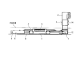
- FIG. 1 shows an appearance of a uniaxial actuator according to an embodiment of the present invention.
- the uniaxial actuator of this embodiment includes an apparatus base 1, a timing belt mechanism 2 disposed on the apparatus base 1, a slider 3 fixed to the timing belt 8 of the timing belt mechanism 2, a motor 4, and a motor 4. And a rotation transmission portion 5 that transmits the driving force of the motor 4 to the timing belt mechanism 2.
- the timing belt mechanism 2 includes a driven pulley portion 6 disposed on one side in the longitudinal direction of the device base 1, a drive side pulley portion 7 disposed on the other side in the longitudinal direction of the device base 1, A timing belt 8 disposed between the driven pulley section 6 and the driving pulley section 7.
- the driven pulley section 6 includes a pulley case 9 fixed to one end of the apparatus base 1, a shaft 10 with an axis extending in the vertical direction and fixed to the pulley case 9, and a rotatable arrangement on the shaft 10.
- the driven side timing pulley 11 is configured.
- the drive-side pulley unit 7 includes a pulley case 12 fixed to the other end of the apparatus mount 1 and a drive-side timing pulley 13 disposed inside the pulley case 12 with the center of rotation directed in the vertical direction. .
- the rotation transmitting unit 5 is rotatably supported by a cylindrical housing 14 disposed on the upper side of the pulley case 12 of the driving side pulley unit 7 and bearings 15 and 16 disposed inside the housing 14.
- a rotation transmission shaft 17 protruding from the opening and connected to the driving side timing pulley 13 of the driving pulley portion 7, and the motor shaft 4 a and the rotation transmission shaft 17 of the motor 4 inserted into the housing from the upper opening of the housing 14.
- a coupling member 18 for coaxially connecting the two.
- the timing belt 8 has the belt width direction in the vertical direction between the driven side timing pulley 11 of the driven side pulley unit 6 and the driving side timing pulley 13 of the driving side pulley unit 7.
- the slider 3 is fixed to the timing belt 8 via a slider fixing member 20.
- a first liquid-tight seal member 21 is attached.
- a second liquid-tight seal member 22 is mounted between the periphery of the upper opening formed in the upper portion of the housing 14 and the end surface of the motor 4 on the side from which the motor shaft 4a projects. Further, a third liquid-tight seal member 23 is also mounted on the upper portion of the bearing 16 that rotatably supports the rotation transmission shaft 17 of the housing 14.
- the driven side timing pulley 11 and the driving side timing pulley 13 are made of a synthetic resin material having corrosion resistance against moisture.
- the device base 1, the slider 3, the pulley case 9 of the driven pulley section 6, the shaft 10, the pulley case 12 of the driving pulley section 7, the rotation transmission shaft 17, and the housing 14 are resistant to moisture such as stainless steel. It is made of a metallic material having properties.
- the rotation of the motor shaft 4a is transmitted to the driving side timing pulley 13 of the driving side pulley portion 7 via the rotation transmission shaft 17 by performing forward / reverse rotation operation of the motor 4, and the timing belt
- the slider 8 is rotated, the slider 3 moves linearly.
- the effect of the uniaxial actuator of this embodiment will be described with reference to FIGS.
- the motor 4 disposed on the upper portion of the rotation transmission unit 5 is positioned above the water surface and is special to the motor 4. Even without a waterproof structure, a sufficient waterproof effect can be secured.
- the timing belt 8 used in the uniaxial actuator of the present embodiment is stretched over the driven side timing pulley 11 and the driving side timing pulley 13 with the belt width direction directed in the vertical direction, and the inner belt teeth are moved up and down. Since it extends in the direction, foreign matter contained in the water is less likely to accumulate between the belt teeth when used in a submerged environment, and the timing belt mechanism can be operated normally.
- the driven side timing pulley 11 and the driving side timing pulley 13 are made of a synthetic resin material having corrosion resistance against moisture
- the device base 1, the slider 3, and the pulley case 9 of the driven side pulley portion 6 Since the shaft 10, the pulley case 12 of the driving pulley section 7, the rotation transmission shaft 17, and the housing 14 are made of a metal material having corrosion resistance against moisture such as stainless steel, the shaft 10 and the pulley 14 can be used in a submerged environment for a long time. Can be used as a single-axis actuator having durability.
- the waterproof effect is enhanced by simply arranging the first to third liquid-tight seal members 21, 22, and 23 at locations where water is likely to enter the motor 4 side inside the rotation transmission unit 5. Since it does not affect load resistance or moment resistance, it can be used as a single-axis actuator with high load specifications.
- the uniaxial actuator according to the present invention is useful for use as a high load specification even in an environment where the slider is submerged.
Landscapes
- Engineering & Computer Science (AREA)
- General Engineering & Computer Science (AREA)
- Mechanical Engineering (AREA)
- Power Engineering (AREA)
- Transmission Devices (AREA)
- Connection Of Motors, Electrical Generators, Mechanical Devices, And The Like (AREA)
- Manipulator (AREA)
- Devices For Conveying Motion By Means Of Endless Flexible Members (AREA)
- Motor Or Generator Frames (AREA)
Priority Applications (2)
| Application Number | Priority Date | Filing Date | Title |
|---|---|---|---|
| CN201480059780.5A CN105684273B (zh) | 2013-12-27 | 2014-12-26 | 单轴致动器 |
| US15/026,077 US9759295B2 (en) | 2013-12-27 | 2014-12-26 | Single axis actuator |
Applications Claiming Priority (2)
| Application Number | Priority Date | Filing Date | Title |
|---|---|---|---|
| JP2013-273044 | 2013-12-27 | ||
| JP2013273044A JP6361137B2 (ja) | 2013-12-27 | 2013-12-27 | 一軸アクチュエータ |
Publications (1)
| Publication Number | Publication Date |
|---|---|
| WO2015098123A1 true WO2015098123A1 (ja) | 2015-07-02 |
Family
ID=53478018
Family Applications (1)
| Application Number | Title | Priority Date | Filing Date |
|---|---|---|---|
| PCT/JP2014/006500 Ceased WO2015098123A1 (ja) | 2013-12-27 | 2014-12-26 | 一軸アクチュエータ |
Country Status (4)
| Country | Link |
|---|---|
| US (1) | US9759295B2 (enExample) |
| JP (1) | JP6361137B2 (enExample) |
| CN (1) | CN105684273B (enExample) |
| WO (1) | WO2015098123A1 (enExample) |
Families Citing this family (1)
| Publication number | Priority date | Publication date | Assignee | Title |
|---|---|---|---|---|
| CN113631838A (zh) * | 2019-04-03 | 2021-11-09 | 三菱电机株式会社 | 卷挂传动装置及机器人 |
Citations (2)
| Publication number | Priority date | Publication date | Assignee | Title |
|---|---|---|---|---|
| JP2006083942A (ja) * | 2004-09-16 | 2006-03-30 | Iai:Kk | アクチュエータ |
| JP2013119917A (ja) * | 2011-12-08 | 2013-06-17 | Smc Corp | 駆動力伝達ベルトの歯飛び防止機構 |
Family Cites Families (5)
| Publication number | Priority date | Publication date | Assignee | Title |
|---|---|---|---|---|
| JP2006043856A (ja) * | 2004-08-09 | 2006-02-16 | Oriental Motor Co Ltd | 搬送装置 |
| DE102010050399A1 (de) * | 2010-11-03 | 2012-05-03 | Hella Kgaa Hueck & Co. | Aktuator |
| JP4982593B2 (ja) * | 2010-07-09 | 2012-07-25 | 日本ムーグ株式会社 | リニアアクチュエータ及び鉄道車両用の揺動制御装置 |
| CN201916434U (zh) * | 2010-12-08 | 2011-08-03 | 无锡富瑞德精密机械有限公司 | 钢带传动机构 |
| JP2012149691A (ja) | 2011-01-18 | 2012-08-09 | Fujifilm Corp | 直動機構 |
-
2013
- 2013-12-27 JP JP2013273044A patent/JP6361137B2/ja active Active
-
2014
- 2014-12-26 CN CN201480059780.5A patent/CN105684273B/zh not_active Expired - Fee Related
- 2014-12-26 US US15/026,077 patent/US9759295B2/en active Active
- 2014-12-26 WO PCT/JP2014/006500 patent/WO2015098123A1/ja not_active Ceased
Patent Citations (2)
| Publication number | Priority date | Publication date | Assignee | Title |
|---|---|---|---|---|
| JP2006083942A (ja) * | 2004-09-16 | 2006-03-30 | Iai:Kk | アクチュエータ |
| JP2013119917A (ja) * | 2011-12-08 | 2013-06-17 | Smc Corp | 駆動力伝達ベルトの歯飛び防止機構 |
Also Published As
| Publication number | Publication date |
|---|---|
| US9759295B2 (en) | 2017-09-12 |
| JP6361137B2 (ja) | 2018-07-25 |
| US20160245378A1 (en) | 2016-08-25 |
| CN105684273B (zh) | 2018-04-03 |
| CN105684273A (zh) | 2016-06-15 |
| JP2015128348A (ja) | 2015-07-09 |
Similar Documents
| Publication | Publication Date | Title |
|---|---|---|
| JP2012050824A5 (enExample) | ||
| JP2008506546A5 (enExample) | ||
| EP1992974A3 (en) | Positioning device | |
| WO2008115066A3 (en) | Device for wave-powered generator | |
| TW200745468A (en) | Hollow shaft motor drive apparatus | |
| DK2001340T3 (da) | Lineær aktuator til møbler | |
| JP2008172995A5 (enExample) | ||
| EP2353508A4 (en) | ULTRASONIC PROBE | |
| JP2009222234A5 (enExample) | ||
| WO2007067659A8 (en) | Rotatable tool and apparatus therefor | |
| JP6361137B2 (ja) | 一軸アクチュエータ | |
| JP5059511B2 (ja) | ロボットアクチュエータにおけるスライダ構造 | |
| HRP20120693T1 (hr) | Brtvljenje za pogon sa perajom | |
| CN102381439A (zh) | 一种船体槽道口封盖装置 | |
| WO2011023166A3 (de) | Einrichtung zur energieübertragung zwischen einem strömenden medium und einer kurbelwelle | |
| JP2011144895A5 (enExample) | ||
| KR101141620B1 (ko) | 로봇핸드 그리퍼의 관절구조 | |
| JP2019045127A5 (enExample) | ||
| JP5269363B2 (ja) | アクチュエータにおける原点出し方法およびアクチュエータにおける原点出しストッパ装置 | |
| KR101398229B1 (ko) | 클린타입 직선로봇 | |
| JPWO2016009623A1 (ja) | 発電デバイス | |
| JP2012180948A5 (enExample) | ||
| JP2011161558A (ja) | ツイストスライド機構及びロボット | |
| JP4816324B2 (ja) | 直線移動装置 | |
| KR101487285B1 (ko) | 러더 어셈블리 |
Legal Events
| Date | Code | Title | Description |
|---|---|---|---|
| 121 | Ep: the epo has been informed by wipo that ep was designated in this application |
Ref document number: 14874586 Country of ref document: EP Kind code of ref document: A1 |
|
| WWE | Wipo information: entry into national phase |
Ref document number: 15026077 Country of ref document: US |
|
| NENP | Non-entry into the national phase |
Ref country code: DE |
|
| 122 | Ep: pct application non-entry in european phase |
Ref document number: 14874586 Country of ref document: EP Kind code of ref document: A1 |