WO2015097997A1 - 入力装置 - Google Patents
入力装置 Download PDFInfo
- Publication number
- WO2015097997A1 WO2015097997A1 PCT/JP2014/006049 JP2014006049W WO2015097997A1 WO 2015097997 A1 WO2015097997 A1 WO 2015097997A1 JP 2014006049 W JP2014006049 W JP 2014006049W WO 2015097997 A1 WO2015097997 A1 WO 2015097997A1
- Authority
- WO
- WIPO (PCT)
- Prior art keywords
- coil
- magnetic pole
- magnetic
- pole forming
- input device
- Prior art date
- Legal status (The legal status is an assumption and is not a legal conclusion. Google has not performed a legal analysis and makes no representation as to the accuracy of the status listed.)
- Ceased
Links
Images







Classifications
-
- H—ELECTRICITY
- H01—ELECTRIC ELEMENTS
- H01H—ELECTRIC SWITCHES; RELAYS; SELECTORS; EMERGENCY PROTECTIVE DEVICES
- H01H36/00—Switches actuated by change of magnetic field or of electric field, e.g. by change of relative position of magnet and switch, by shielding
- H01H36/02—Switches actuated by change of magnetic field or of electric field, e.g. by change of relative position of magnet and switch, by shielding actuated by movement of a float carrying a magnet
-
- G—PHYSICS
- G06—COMPUTING OR CALCULATING; COUNTING
- G06F—ELECTRIC DIGITAL DATA PROCESSING
- G06F3/00—Input arrangements for transferring data to be processed into a form capable of being handled by the computer; Output arrangements for transferring data from processing unit to output unit, e.g. interface arrangements
- G06F3/01—Input arrangements or combined input and output arrangements for interaction between user and computer
- G06F3/016—Input arrangements with force or tactile feedback as computer generated output to the user
-
- B—PERFORMING OPERATIONS; TRANSPORTING
- B60—VEHICLES IN GENERAL
- B60K—ARRANGEMENT OR MOUNTING OF PROPULSION UNITS OR OF TRANSMISSIONS IN VEHICLES; ARRANGEMENT OR MOUNTING OF PLURAL DIVERSE PRIME-MOVERS IN VEHICLES; AUXILIARY DRIVES FOR VEHICLES; INSTRUMENTATION OR DASHBOARDS FOR VEHICLES; ARRANGEMENTS IN CONNECTION WITH COOLING, AIR INTAKE, GAS EXHAUST OR FUEL SUPPLY OF PROPULSION UNITS IN VEHICLES
- B60K35/00—Instruments specially adapted for vehicles; Arrangement of instruments in or on vehicles
- B60K35/10—Input arrangements, i.e. from user to vehicle, associated with vehicle functions or specially adapted therefor
-
- B—PERFORMING OPERATIONS; TRANSPORTING
- B60—VEHICLES IN GENERAL
- B60K—ARRANGEMENT OR MOUNTING OF PROPULSION UNITS OR OF TRANSMISSIONS IN VEHICLES; ARRANGEMENT OR MOUNTING OF PLURAL DIVERSE PRIME-MOVERS IN VEHICLES; AUXILIARY DRIVES FOR VEHICLES; INSTRUMENTATION OR DASHBOARDS FOR VEHICLES; ARRANGEMENTS IN CONNECTION WITH COOLING, AIR INTAKE, GAS EXHAUST OR FUEL SUPPLY OF PROPULSION UNITS IN VEHICLES
- B60K35/00—Instruments specially adapted for vehicles; Arrangement of instruments in or on vehicles
- B60K35/20—Output arrangements, i.e. from vehicle to user, associated with vehicle functions or specially adapted therefor
- B60K35/21—Output arrangements, i.e. from vehicle to user, associated with vehicle functions or specially adapted therefor using visual output, e.g. blinking lights or matrix displays
- B60K35/22—Display screens
-
- B—PERFORMING OPERATIONS; TRANSPORTING
- B60—VEHICLES IN GENERAL
- B60K—ARRANGEMENT OR MOUNTING OF PROPULSION UNITS OR OF TRANSMISSIONS IN VEHICLES; ARRANGEMENT OR MOUNTING OF PLURAL DIVERSE PRIME-MOVERS IN VEHICLES; AUXILIARY DRIVES FOR VEHICLES; INSTRUMENTATION OR DASHBOARDS FOR VEHICLES; ARRANGEMENTS IN CONNECTION WITH COOLING, AIR INTAKE, GAS EXHAUST OR FUEL SUPPLY OF PROPULSION UNITS IN VEHICLES
- B60K35/00—Instruments specially adapted for vehicles; Arrangement of instruments in or on vehicles
- B60K35/20—Output arrangements, i.e. from vehicle to user, associated with vehicle functions or specially adapted therefor
- B60K35/25—Output arrangements, i.e. from vehicle to user, associated with vehicle functions or specially adapted therefor using haptic output
-
- B—PERFORMING OPERATIONS; TRANSPORTING
- B60—VEHICLES IN GENERAL
- B60K—ARRANGEMENT OR MOUNTING OF PROPULSION UNITS OR OF TRANSMISSIONS IN VEHICLES; ARRANGEMENT OR MOUNTING OF PLURAL DIVERSE PRIME-MOVERS IN VEHICLES; AUXILIARY DRIVES FOR VEHICLES; INSTRUMENTATION OR DASHBOARDS FOR VEHICLES; ARRANGEMENTS IN CONNECTION WITH COOLING, AIR INTAKE, GAS EXHAUST OR FUEL SUPPLY OF PROPULSION UNITS IN VEHICLES
- B60K35/00—Instruments specially adapted for vehicles; Arrangement of instruments in or on vehicles
- B60K35/85—Arrangements for transferring vehicle- or driver-related data
-
- G—PHYSICS
- G06—COMPUTING OR CALCULATING; COUNTING
- G06F—ELECTRIC DIGITAL DATA PROCESSING
- G06F3/00—Input arrangements for transferring data to be processed into a form capable of being handled by the computer; Output arrangements for transferring data from processing unit to output unit, e.g. interface arrangements
- G06F3/01—Input arrangements or combined input and output arrangements for interaction between user and computer
-
- G—PHYSICS
- G06—COMPUTING OR CALCULATING; COUNTING
- G06F—ELECTRIC DIGITAL DATA PROCESSING
- G06F3/00—Input arrangements for transferring data to be processed into a form capable of being handled by the computer; Output arrangements for transferring data from processing unit to output unit, e.g. interface arrangements
- G06F3/01—Input arrangements or combined input and output arrangements for interaction between user and computer
- G06F3/011—Arrangements for interaction with the human body, e.g. for user immersion in virtual reality
- G06F3/014—Hand-worn input/output arrangements, e.g. data gloves
-
- G—PHYSICS
- G06—COMPUTING OR CALCULATING; COUNTING
- G06F—ELECTRIC DIGITAL DATA PROCESSING
- G06F3/00—Input arrangements for transferring data to be processed into a form capable of being handled by the computer; Output arrangements for transferring data from processing unit to output unit, e.g. interface arrangements
- G06F3/01—Input arrangements or combined input and output arrangements for interaction between user and computer
- G06F3/03—Arrangements for converting the position or the displacement of a member into a coded form
- G06F3/033—Pointing devices displaced or positioned by the user, e.g. mice, trackballs, pens or joysticks; Accessories therefor
- G06F3/0354—Pointing devices displaced or positioned by the user, e.g. mice, trackballs, pens or joysticks; Accessories therefor with detection of two-dimensional [2D] relative movements between the device, or an operating part thereof, and a plane or surface, e.g. 2D mice, trackballs, pens or pucks
-
- G—PHYSICS
- G06—COMPUTING OR CALCULATING; COUNTING
- G06F—ELECTRIC DIGITAL DATA PROCESSING
- G06F3/00—Input arrangements for transferring data to be processed into a form capable of being handled by the computer; Output arrangements for transferring data from processing unit to output unit, e.g. interface arrangements
- G06F3/01—Input arrangements or combined input and output arrangements for interaction between user and computer
- G06F3/03—Arrangements for converting the position or the displacement of a member into a coded form
- G06F3/033—Pointing devices displaced or positioned by the user, e.g. mice, trackballs, pens or joysticks; Accessories therefor
- G06F3/0354—Pointing devices displaced or positioned by the user, e.g. mice, trackballs, pens or joysticks; Accessories therefor with detection of two-dimensional [2D] relative movements between the device, or an operating part thereof, and a plane or surface, e.g. 2D mice, trackballs, pens or pucks
- G06F3/03548—Sliders, in which the moving part moves in a plane
-
- B—PERFORMING OPERATIONS; TRANSPORTING
- B60—VEHICLES IN GENERAL
- B60K—ARRANGEMENT OR MOUNTING OF PROPULSION UNITS OR OF TRANSMISSIONS IN VEHICLES; ARRANGEMENT OR MOUNTING OF PLURAL DIVERSE PRIME-MOVERS IN VEHICLES; AUXILIARY DRIVES FOR VEHICLES; INSTRUMENTATION OR DASHBOARDS FOR VEHICLES; ARRANGEMENTS IN CONNECTION WITH COOLING, AIR INTAKE, GAS EXHAUST OR FUEL SUPPLY OF PROPULSION UNITS IN VEHICLES
- B60K2360/00—Indexing scheme associated with groups B60K35/00 or B60K37/00 relating to details of instruments or dashboards
- B60K2360/143—Touch sensitive instrument input devices
Definitions
- This disclosure relates to an input device to which an operating force is input.
- Patent Document 1 discloses an input device including an operation knob to which an operation force is input and a main body that supports the operation knob so that the operation knob can be moved by the input of the operation force.
- the input device further includes two voice coil motors.
- Each of the two voice coil motors has a magnet that forms a magnetic pole and a voice coil that passes a magnetic flux generated by the magnet, and functions as an actuator.
- each electromagnetic force generated by applying a current to each voice coil acts on the operation knob as an operation reaction force in directions orthogonal to each other. According to such a configuration, by controlling the current applied to each voice coil, the input device can make the user feel an operation reaction force of arbitrary strength through the operation knob.
- Patent Document 1 yokes forming a magnetic circuit are individually provided in each voice coil motor. Therefore, the magnetic flux generated by the magnet of one voice coil motor only passes through the voice coil in the motor, and does not pass through the voice coil provided in the other voice coil motor. In such a configuration, in order to improve the density of the magnetic flux passing through each voice coil, it is necessary to strengthen the individual magnets provided in each voice coil motor, and an increase in the amount of material used to form the magnets is inevitable. It was.
- An object of the present disclosure is to provide an input device that can increase an operation reaction force that can be applied to an input unit such as an operation knob while suppressing the amount of a material for forming a magnetic pole forming unit such as a magnet.
- An input device includes an input unit, a support unit, a first actuator, a second actuator, and a magnetic path forming body.
- the input unit receives an operation force in a direction along the operation plane.
- the support portion supports the input portion so as to be movable along the operation plane by inputting the operation force.
- the first actuator has a first magnetic pole forming portion that forms a magnetic pole, and a first coil through which a magnetic flux generated by the first magnetic pole forming portion passes, and generates an electromagnetic force generated by applying a current to the first coil. , And acting on the input unit as an operation reaction force in the first direction along the operation plane.
- the second actuator has a second magnetic pole forming portion that forms a magnetic pole, and a second coil through which a magnetic flux generated by the second magnetic pole forming portion passes, and generates an electromagnetic force generated by applying a current to the second coil. , And acting on the input unit as an operation reaction force in a second direction along the operation plane and intersecting the first direction.
- the magnetic path forming body forms a magnetic circuit that guides the magnetic flux generated by the first magnetic pole forming portion so as to pass through the second coil and guides the magnetic flux generated by the second magnetic pole forming portion so as to pass through the first coil. To do.
- the magnetic flux generated by the first magnetic pole forming portion in the first actuator not only passes through the first coil of the first actuator but also the magnetic circuit formed by the magnetic path forming body. Is passed through the second coil of the second actuator. Similarly, the magnetic flux generated by the second magnetic pole forming portion in the second actuator not only passes through the second coil of the second actuator but is also guided by the magnetic circuit, thereby having the first actuator. Pass through the first coil.
- the configuration in which the magnetic flux generated by the magnetic pole forming part of one actuator is guided to the coil of the other actuator through the magnetic circuit can improve both the magnetic flux densities passing through the coils of the two actuators. Therefore, each electromagnetic force that can be generated by each actuator increases together. Therefore, it is possible to increase the operation reaction force that can be applied to the input portion while suppressing the amount of the forming material for each magnetic pole forming portion.
- FIG. 1 is a diagram for describing a configuration of a display system including an operation input device according to the first embodiment of the present disclosure.
- FIG. 2 is a diagram for explaining the arrangement of the operation input device in the passenger compartment.
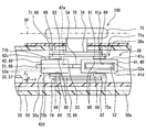
- FIG. 3 is a cross-sectional view for explaining the mechanical configuration of the operation input device.
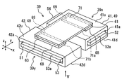
- FIG. 4 is a perspective view of the reaction force generator.
- FIG. 5 is a bottom view of the reaction force generator as seen from the arrow V in FIG.
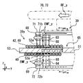
- FIG. 6 is a diagram schematically showing an aspect of the magnetic flux surrounding the magnetic circuit, and is a cross-sectional view taken along the line VI-VI in FIG. FIG.
- FIG. 7 is a diagram schematically showing an aspect of the magnetic flux surrounding the magnetic circuit, and is a cross-sectional view taken along the line VII-VII in FIG.
- FIG. 8 is an exploded perspective view of the reaction force generation unit, and is a diagram schematically illustrating the manner of magnetic flux around the magnetic circuit.
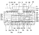
- FIG. 9 is a cross-sectional view of the operation input device according to the second embodiment of the present disclosure.
- FIG. 10 is a perspective view of a reaction force generator according to the second embodiment.
- FIG. 11 is a bottom view of the reaction force generator as seen from the arrow XI in FIG.
- FIG. 12 is a diagram schematically showing an aspect of the magnetic flux surrounding the magnetic circuit, and is a cross-sectional view taken along line XII-XII in FIG.
- FIG. 13 is a diagram schematically showing an aspect of magnetic flux surrounding the magnetic circuit, and is a cross-sectional view taken along line XIII-XIII in FIG.
- FIG. 14 is a diagram schematically showing the manner of magnetic flux around the magnetic circuit of the reaction force generator according to the third embodiment.
- FIG. 15 is a diagram schematically illustrating the manner of magnetic flux around the magnetic circuit of the reaction force generation unit according to the third embodiment.
- An operation input device 100 according to the first embodiment of the present disclosure shown in FIG. 1 is mounted on a vehicle and includes a display system 10 together with a display in the vehicle interior, for example, a navigation device 20 or a head-up display device 120 (see FIG. 2). It is composed. As shown in FIG. 2, the operation input device 100 is installed at a position adjacent to the palm rest 19 at the center console of the vehicle, and exposes the operation knob 73 in a range that can be easily reached by the operator. The operation knob 73 is displaced in the direction of the input operation force when the operation force is input by the operator's hand H or the like.
- the navigation device 20 is installed in the instrument panel of the vehicle and exposes the display screen 22 toward the driver's seat.
- the display screen 22 displays a plurality of icons associated with a predetermined function, a pointer 80 for selecting an arbitrary icon, and the like.
- the pointer 80 moves on the display screen 22 in a direction corresponding to the input direction of the operation force.
- the navigation device 20 is connected to a communication bus 90 and is capable of network communication with the operation input device 100 and the like.
- the navigation device 20 includes a display control unit 23 that draws an image displayed on the display screen 22 and a liquid crystal display 21 that continuously displays the image drawn by the display control unit 23 on the display screen 22.
- the operation input device 100 is connected to a communication bus 90, an external battery 95, and the like.
- the operation input device 100 can communicate with the navigation device 20 located remotely via the communication bus 90. Further, the operation input device 100 is supplied with electric power necessary for the operation of each component from the battery 95.
- the operation input device 100 is electrically configured by a communication control unit 35, an operation detection unit 31, a reaction force generation unit 39, a reaction force control unit 37, an operation control unit 33, and the like.
- the communication control unit 35 outputs the information processed by the operation control unit 33 to the communication bus 90. In addition, the communication control unit 35 acquires information output from another in-vehicle device to the communication bus 90 and outputs the information to the operation control unit 33.
- the operation detection unit 31 detects the position of the operation knob 73 (see FIG. 2) moved by the input of the operation force. The operation detection unit 31 outputs operation information indicating the detected position of the operation knob 73 to the operation control unit 33.
- the reaction force generator 39 is configured to generate an operation reaction force on the operation knob 73, and includes an actuator such as a voice coil motor.
- the reaction force generation unit 39 applies an operation reaction force to the operation knob 73 (see FIG. 2) when the pointer 80 (see FIG. 2) overlaps the icon on the display screen 22, for example, so-called reaction force feedback. , Causing the operator to feel the touch of a pseudo icon.
- the reaction force control unit 37 is configured by, for example, a microcomputer for performing various calculations.
- the reaction force control unit 37 controls the direction and strength of the operation reaction force applied from the reaction force generation unit 39 to the operation knob 73 based on the reaction force information acquired from the operation control unit 33.
- the operation control unit 33 is configured by, for example, a microcomputer for performing various calculations.
- the operation control unit 33 acquires operation information detected by the operation detection unit 31 and outputs the operation information to the communication bus 90 through the communication control unit 35.
- the operation control unit 33 calculates the direction and strength of the operation reaction force applied to the operation knob 73 (see FIG. 2), and outputs the calculation result to the reaction force control unit 37 as reaction force information.
- the operation input device 100 is mechanically configured by a movable portion 70, a fixed portion 50, and the like.
- the movable portion 70 has a knob base 74 that holds a pair of movable yokes 71 and 72 described later, and the operation knob 73 described above.
- the movable portion 70 is provided so as to be relatively movable with respect to the fixed portion 50 in the x-axis direction and the y-axis direction along the virtual operation plane OP.
- the movable unit 70 is preliminarily defined by the fixed unit 50 in a range in which the movable unit 70 can move in the x-axis direction and the y-axis direction. When the movable part 70 is released from the applied operating force, the movable part 70 returns to the reference position as a reference.
- the fixed part 50 has a housing 50a and a circuit board 59, and holds a fixed yoke 51 described later.
- the housing 50a accommodates the components such as the circuit board 59 and the reaction force generating portion 39 while supporting the movable portion 70 so as to be relatively movable.
- the circuit board 59 is fixed in the housing 50a so that the plate surface direction is along the operation plane OP.
- the circuit board 59 is mounted with a microcomputer or the like constituting the operation control unit 33, the reaction force control unit 37, and the like.
- the reaction force generator 39 includes a first voice coil motor (VCM) 39x and a second VCM 39y that function as actuators, a fixed yoke 51, two movable yokes 71 and 72, and the like.
- the first VCM 39 x has a first coil 41 and two magnets 61 and 62.
- the second VCM 39y includes a second coil 42 and two magnets 63 and 64.
- the coils 41 and 42 are formed by winding a wire made of a nonmagnetic material such as copper into a flat cylindrical shape as a winding 49.
- the cross section orthogonal to the winding axis direction of the winding 49 is formed in a rectangular shape.
- Each winding 49 is wound until the thickness of the cylindrical wall of each coil 41, 42 is about 3 mm, for example.
- accommodating chambers 41a and 42a extending in the winding axis direction are formed on the inner peripheral side of the wound winding 49.
- Each coil 41, 42 is electrically connected to the reaction force control unit 37 via a wiring pattern provided on the circuit board 59, and a current is individually applied to each winding 49 by the reaction force control unit 37.
- the coils 41 and 42 are arranged along the y-axis with a slight gap therebetween.
- Each of the coils 41 and 42 is fixed to the fixing portion 50 such as the circuit board 59 so that the winding axis direction of the winding 49 is along the operation plane OP.
- the winding axis direction of one coil (hereinafter “first coil”) 41 is along the x-axis.
- the winding axis direction of the other coil (hereinafter “second coil”) 42 is along the y-axis.
- Each coil 41, 42 forms a pair of coil side surfaces 41u, 41d, 42u, 42d along the operation plane OP, respectively.
- each of the coils 41 and 42 one of the coils 41 and 42 facing the operation knob 73 side is defined as an upper coil side surface 41u and 42u, and the other facing the circuit board 59 side is defined as a lower coil side surface 41d and 42d.
- Each coil side surface 41u, 41d, 42u, 42d is formed in a substantially quadrilateral shape with each side along the x-axis or y-axis.
- the magnets 61 to 64 are neodymium magnets or the like, and are formed in a substantially quadrangular plate shape having a longitudinal direction.
- the two magnets 61 and 62 are located away from each other in the z-axis direction substantially orthogonal to the operation plane OP, and are aligned in the z-axis direction.
- the other two magnets 63 and 64 are located apart from each other in the z-axis direction and are aligned in the z-axis direction.
- Each of the magnets 61 to 64 is provided with a magnetized surface 68 and a mounting surface 69 formed in a smooth flat shape. In each of the magnets 61 to 64, the magnetic poles of the magnetized surface 68 and the mounting surface 69 are different from each other (see also FIGS. 6 and 7).
- Each attachment surface 69 of the two magnets 61 and 63 is attached to the movable yoke 71 so that the long side is along the y-axis.
- the magnetized surface 68 of the magnet 61 held by the movable yoke 71 is opposed to the upper coil side surface 41u of the first coil 41 with a predetermined interval in the z-axis direction.
- the magnetized surface 68 of the magnet 63 held by the movable yoke 71 faces the upper coil side surface 42u of the second coil 42 while leaving a predetermined interval in the z-axis direction.
- Each attachment surface 69 of the other two magnets 62 and 64 is attached to the movable yoke 72 so that the long side is along the y-axis.
- the magnetized surface 68 of the magnet 62 held by the movable yoke 72 is opposed to the lower coil side surface 41d of the first coil 41 with a predetermined interval in the z-axis direction.
- the magnetized surface 68 of the magnet 64 held by the movable yoke 72 faces the lower coil side surface 42d of the second coil 42 with a predetermined interval in the z-axis direction.
- Each magnetized surface 68 is located at the center of each of the opposing coil side surfaces 41u, 41d, 42u, 42d when the movable portion 70 is returned to the reference position.
- the magnetic flux generated by each of the magnets 61 and 62 passes (penetrates) the winding 49 of the first coil 41 in the z-axis direction. Therefore, when a charge moves in the winding 49 placed in the magnetic field by applying a current to the first coil 41, a Lorentz force is generated in each charge.
- the first VCM 39x generates the electromagnetic force EMF_x in the x-axis direction between the first coil 41 and the magnets 61 and 62.
- the generated electromagnetic force EMF_x is also reversed, and the direction is in the opposite direction along the x axis.
- the magnetic flux generated by each of the magnets 63 and 64 passes (penetrates) the winding 49 of the second coil 42 in the z-axis direction. Therefore, when a charge moves in the winding 49 placed in the magnetic field by applying a current to the second coil 42, a Lorentz force is generated in each charge.
- the second VCM 39y generates the electromagnetic force EMF_x in the y-axis direction between the second coil 42 and the magnets 63 and 64.
- the generated electromagnetic force EMF_y is also reversed, and the direction is in the opposite direction along the y-axis.
- the fixed yoke 51 shown in FIGS. 3 to 5 is made of a magnetic material such as soft iron and electromagnetic steel plate.
- the fixed yoke 51 is provided with two coil side yoke portions 52 and 53 and a connecting portion 54.
- the coil side yoke portions 52 and 53 are formed in a flat plate shape.
- first coil side yoke part (hereinafter, “first coil side yoke part”) 52 is inserted into the accommodation chamber 41a of the first coil 41 and penetrates the accommodation chamber 41a.
- First opposing surfaces 52a are formed on both surfaces of the first coil side yoke portion 52 accommodated in the accommodation chamber 41a.
- the two first opposing surfaces 52a are located on the inner peripheral side of the first coil 41, and are arranged so as to sandwich the coil 41 from both the inner and outer sides together with the magnets 61 and 62 disposed on the outer peripheral side of the first coil 41.
- the magnets 61 and 62 are individually opposed to the magnetized surfaces 68.
- the other coil side yoke part (hereinafter referred to as “second coil side yoke part”) 53 is inserted into the accommodation chamber 42a of the second coil 42 and penetrates the accommodation chamber 42a.
- a second opposing surface 53a is formed on both surfaces of the second coil side yoke portion 53 accommodated in the accommodation chamber 42a.
- the two second facing surfaces 53a are located on the inner peripheral side of the second coil 42, and are arranged so as to sandwich the coil 42 from both the inner and outer sides together with the magnets 63 and 64 disposed on the outer peripheral side of the second coil 42.
- the magnets 63 and 64 are individually opposed to the magnetized surfaces 68.
- the magnetic flux generated by each of the magnets 63 and 64 induced in the second coil side yoke portion 53 passes (penetrates) the winding 49 of the second coil 42 in the z-axis direction.
- the connecting portion 54 is bent in an L shape along the coils 41 and 42.
- the connecting portion 54 extends from the first coil side yoke portion 52 accommodated in the first coil 41 to the second coil side yoke portion 53 accommodated in the second coil 42, thereby providing two coil side yoke portions 52. , 53 are connected.
- the fixed yoke 51 extending from the storage chamber 41a of the first coil 41 to the storage chamber 42a of the second coil 42 is formed.
- the movable yokes 71 and 72 are formed of a magnetic material such as soft iron and an electromagnetic steel plate, like the fixed yoke 51.
- Each of the movable yokes 71 and 72 is formed of a rectangular flat plate material and has substantially the same shape.
- the movable yokes 71 and 72 are held by the knob base 74 so as to face each other while sandwiching the two coils 41 and 42 in the z-axis direction.
- first holding surfaces 71a and 72a and second holding surfaces 71b and 72b are formed.
- One movable yoke 71 holds the mounting surface 69 of the magnet 61 by the first holding surface 71a and holds the mounting surface 69 of the magnet 63 by the second holding surface 71b.
- the other movable yoke 72 holds the mounting surface 69 of the magnet 64 by the second holding surface 72b while holding the mounting surface 69 of the magnet 62 by the first holding surface 72a.
- the fixed yoke 51 and the two movable yokes 71 and 72 described above form the magnetic circuit 65 of the reaction force generating portion 39 shown in FIGS.
- the magnetic circuit 65 guides the magnetic flux generated by the magnets 61 and 62 of the first VCM 39x to the second VCM 39y and has the shape of the magnets 63 and 64 of the second VCM 39y. The generated magnetic flux is guided to the first VCM 39x.
- the magnetic poles of the magnetized surfaces 68 facing the first coil 41 are the same. Therefore, the directions of the magnetic fluxes generated by the magnets 61 and 62 are opposite to each other along the z axis. Therefore, the magnetic flux which goes to each 1st holding surface 71a, 72a from each 1st opposing surface 52a arises. These magnetic fluxes enter the movable yokes 71 and 72 from the first holding surfaces 71a and 72a, respectively, and go to the second holding surfaces 71b and 72b from the first holding surfaces 71a and 72a in the movable yokes 71 and 72, respectively. .
- each of the magnets 63 and 64 of the second VCM 39y shown in FIGS. 7 and 8 the magnetic poles of the respective magnetized surfaces 68 facing the second coil 42 are the same as each other and are opposed to the first coil 41. It is different from the magnetic poles of the two magnetized surfaces 68 (see also FIG. 6). Therefore, the direction of the magnetic flux generated by each of the magnets 63 and 64 is a direction facing each other along the z axis. Therefore, the magnetic flux which goes to each 2nd opposing surface 53a arises from each 2nd holding surface 71b, 72b.
- the magnetic flux induced by each of the movable yokes 71 and 72 enters the second coil side yoke portion 53 from each second facing surface 53a, passes through the connecting portion 54, and then enters the first coil side yoke portion 52. Head. Then, the magnetic flux guided in the fixed yoke 51 travels again from the first opposing surfaces 52a to the first holding surfaces 71a and 72a (see FIG. 7).
- the magnetic flux generated by the magnets 61 and 62 in the first VCM 39x is not only passed through the first coil 41 of the VCM 39x but also guided by the magnetic circuit 65.
- the second coil 42 of the second VCM 39y is passed.
- the magnetic flux generated by each of the magnets 63 and 64 in the second VCM 39y not only passes through the second coil 42 but also passes through the first coil 41 of the first VCM 39x by being guided by the magnetic circuit 65.
- the magnetic flux density between each first opposing surface 52a and each first holding surface 71a, 72a and the magnetic flux density between each second opposing surface 53a and each second holding surface 71b, 72b are both VCM 39x, Compared with the form in which the magnetic circuit of 39y is formed individually, it becomes higher.
- the magnetic flux EMF_x that can be generated by the first VCM 39x is increased by improving the magnetic flux density penetrating the winding 49 of the first coil 41 in the z-axis direction.
- the electromagnetic force EMF_x that can be generated by the second VCM 39y is increased by improving the magnetic flux density penetrating the winding 49 of the second coil 42 in the z-axis direction.
- the two magnets 61 and 62 and the first facing surfaces 52a face each other in the z-axis direction while sandwiching the winding 49 of the first coil 41 from both the inside and outside. ing. Therefore, the magnetic attraction force attracting the first facing surface 52a facing one magnet 61 can cancel the magnetic attraction force attracting the first facing surface 52a facing the other magnet 62.
- the magnetic attraction force that attracts the second facing surface 53a that the one magnet 63 faces can cancel the magnetic attraction force that attracts the second facing surface 53a that the other magnet 64 faces.
- the direction of the magnetic flux generated by these magnets 61 to 64 and around the magnetic circuit 65 is made uniform. Therefore, in the magnetic circuit 65, the magnetic fluxes generated by the magnets 61 to 64 do not cancel each other, so that the density of the magnetic flux penetrating the coils 41 and 42 in the z-axis direction is further increased. Therefore, each electromagnetic force EMF_x, EMF_y that can be generated by each VCM 39x, 39y can be further increased.
- the movable yokes 71 and 72 directly hold the magnets 61 to 64 by the holding surfaces 71a, 72a, 71b, and 72b. Therefore, the magnetic flux generated by each of the magnets 61 to 64 can enter the movable yokes 71 and 72 without substantial loss, and can travel around the magnetic circuit 65. According to the above, the density of the magnetic flux penetrating each coil 41, 42 in the z-axis direction can be further improved, and as a result, the electromagnetic forces EMF_x, EMF_y can be further increased.
- the magnets 61 and 62 and the magnets 63 and 64 are arranged in the z-axis direction. Therefore, the magnetic attractive force between the magnets 61 to 64 and the fixed yoke 51 as described above acts in the z-axis direction and does not substantially act in the x-axis direction and the y-axis direction along the operation plane OP. Therefore, the movement of the movable part 70 in the direction along the operation plane OP is smoother without being disturbed by the magnetic attractive force. Such an effect is particularly effective in the above-described configuration in which the magnetic attraction force is enhanced by improving the magnetic flux density by connecting the magnetic circuits 65 of the VCMs 39x and 39y.
- the relative position of the movable unit 70 with respect to the fixed unit 50 is shifted in the z-axis direction, and the distance between the magnets 61 and 63 and the upper coil side surfaces 41u and 42u is increased.
- the Lorentz force generated at the upper coil side surfaces 41u and 42u is reduced.
- the distance between the magnets 62 and 64 and the lower coil side surfaces 41d and 42d is reduced by the above-described shift in the z-axis direction. Therefore, the Lorentz force generated at the lower coil side surfaces 41d and 42d can be increased to compensate for the Lorentz force reduction of the upper coil side surfaces 41u and 42u.
- each VCM 39x, 39y the electromagnetic forces EMF_x and EMF_y that can be generated can be maintained.
- the magnetic attractive force generated in each of the two VCMs 39x and 39y is balanced in the z-axis direction. Therefore, it is possible to avoid a situation in which the magnetic attraction force causes a rotation moment that tilts the operation knob 73 with respect to the operation plane OP.
- a fixed yoke 51 that extends between the storage chambers 41a and 42a of the coils 41 and 42, a pair of movable yokes 71 and 72 that sandwich the coils 41 and 42 in the z-axis direction, and the like.
- the magnetic circuit 65 is formed by the combination.
- each coil 41 which requires the electrical connection to the reaction force control part 37, 42 becomes a fixed side. Therefore, since it is not necessary to form a wiring or the like considering the movement of the coils 41 and 42, the configuration of the operation input device 100 can be simplified.
- the operation input device 100 corresponds to an “input device”
- the first VCM 39x corresponds to a “first actuator”
- the second VCM 39y corresponds to a “second actuator”.
- the storage chambers 41a and 42a correspond to an “inner peripheral space”
- the fixed portion 50 corresponds to a “support portion”
- the movable portion 70 corresponds to an “input portion”.
- the magnets 61 and 62 correspond to the “first magnetic pole forming portion”
- the magnets 63 and 64 correspond to the “second magnetic pole forming portion”.
- the fixed yoke 51 corresponds to an “inner magnetic yoke”
- the movable yokes 71 and 72 correspond to an “outer magnetic yoke”.
- the second embodiment of the present disclosure shown in FIGS. 9 to 13 is a modification of the first embodiment.
- the reaction force generation unit 239 of the operation input device 200 according to the second embodiment includes a first VCM 239x and a second VCM 239y, a magnetic path forming body 266 including a movable yoke 251 and two fixed yokes 271, 272, and the like.
- the first VCM 239x includes a first coil 241 and two magnets 261 and 262.
- the second VCM 239y has a second coil 242 and two magnets 263, 264.
- the coils 241 and 242 shown in FIGS. 9 to 11 have a configuration corresponding to the coils 41 and 42 (see FIG. 3) of the first embodiment.
- Each of the coils 241 and 242 forms storage chambers 241a and 242a, upper coil side surfaces 241u and 242u, and lower coil side surfaces 241d and 242d, as in the first embodiment.
- the magnets 261 to 264 and the movable yoke 251 are stored in each of the storage chambers 241a and 242a.
- the upper coil side surfaces 241 u and 242 u are attached to the fixed yoke 271.
- Each of the lower coil side surfaces 241 d and 242 d is attached to the fixed yoke 272.
- the four magnets 261 to 264 have a configuration corresponding to each of the magnets 61 to 64 (see FIG. 3) of the first embodiment, and form a mounting surface 269 and a magnetized surface 268. Each attachment surface 269 is attached to the movable yoke 251 so that the long side is along the y-axis.
- the magnets 261 and 262 are housed in the housing chamber 241a of the first coil 241 and are disposed so as to sandwich the movable yoke 251 from both sides in the z-axis direction.
- the magnets 263 and 264 are housed in the housing chamber 242a of the second coil 242, and are disposed so as to sandwich the movable yoke 251 from both sides in the z-axis direction.
- the movable yoke 251 is suspended by the knob base 74 while being separated from the coils 241 and 242 and the fixed yokes 271 and 272.
- the movable yoke 251 is provided with two magnet side yoke portions 252 and 253 formed in a flat plate shape and a connecting portion 254 that connects the magnet side yoke portions 252 and 253 to each other.
- first magnet side yoke part 252 is inserted into the accommodating chamber 241 a of the first coil 241.
- First holding surfaces 252a and 252b are formed on both surfaces of the first magnet side yoke portion 252 housed in the housing chamber 241a.
- the first magnet side yoke portion 252 holds the mounting surface 269 of the magnet 261 by one first holding surface 252a, and holds the mounting surface 269 of the magnet 262 by the other first holding surface 252b.
- the other magnet side yoke part (hereinafter, “second magnet side yoke part”) 253 is inserted into the storage chamber 242a of the second coil 242.
- Second holding surfaces 253a and 253b are formed on both surfaces of the second magnet side yoke portion 253 housed in the housing chamber 242a.
- the second magnet side yoke portion 253 holds the mounting surface 269 of the magnet 263 by one second holding surface 253a, and holds the mounting surface 269 of the magnet 264 by the other second holding surface 253b.
- the connecting portion 254 is bent in an L shape along the coils 241 and 242. A gap corresponding to the maximum stroke amount of the operation knob 73 is provided between the connecting portion 254 and the coils 241 and 242.
- the connecting portion 254 connects the two magnet side yoke portions 252 and 253, thereby forming a movable yoke 251 extending from the accommodation chamber 241 a of the first coil 241 to the accommodation chamber 242 a of the second coil 242.
- the fixed yokes 271 and 272 are both formed of a rectangular flat plate and have substantially the same shape.
- the fixed yokes 271 and 272 are arranged to face each other while sandwiching the two coils 241 and 242 from both sides in the z-axis direction, and are fixed to the fixed portion 50.
- Each of the fixed yokes 271 and 272 is formed with first opposing surfaces 271a and 272a, second opposing surfaces 271b and 272b, and openings 271c and 272c.
- the two first opposing surfaces 271a and 272a are individually connected to the respective magnetized surfaces 268 of the magnets 261 and 262 so as to sandwich the first coil 241 from both the inside and outside together with the magnets 261 and 262 arranged in the storage chamber 241a. Are arranged opposite to each other.
- the two second facing surfaces 271b and 272b are magnetized surfaces of the magnets 263 and 264 so as to sandwich the second coil 242 from both the inside and outside with the magnets 263 and 264 disposed in the storage chamber 242a.
- 268 is arranged to face each other individually.
- the openings 271c and 272c are formed in a rectangular shape whose longitudinal direction is the y-axis direction, and penetrate the fixed yokes 271 and 272 in the plate thickness direction.
- the opening 271c allows a portion (not shown) of the knob base 74 that holds the movable yoke 251 to pass therethrough.
- the above-described movable yoke 251 and the two fixed yokes 271 and 272 form a magnetic circuit 265 of the reaction force generator 239 shown in FIGS.
- the magnetic fluxes generated by the two magnets 261 and 262 having the magnetized surface 268 as the same magnetic pole are in opposite directions. Therefore, the magnetic flux which goes to each 1st opposing surface 271a, 272a arises from each 1st holding surface 252a, 252b, penetrating the 1st coil 241 to a z-axis direction.
- These magnetic fluxes enter the fixed yokes 271 and 272 from the first opposed surfaces 271a and 272a, and the first opposed surfaces 271a and 272a and the second opposed surface 271b shown in FIG. , 272b.
- the magnetic fluxes generated by the two magnets 263 and 264 having the magnetized surface 268 as the same magnetic pole are in opposite directions. Therefore, a magnetic flux is generated from each of the second opposing surfaces 271b and 272b toward the second holding surfaces 253a and 253b while penetrating the second coil 242 in the z-axis direction.
- the magnetic flux induced by the fixed yokes 271 and 272 enters the second magnet side yoke portion 253 from the second holding surfaces 253a and 253b, passes through the connecting portion 254, and is shown in FIG. Head to part 252.
- the magnetic flux generated by each of the magnets 261 and 262 not only passes through the first coil 241 of the first VCM 239 x but also is guided by the magnetic circuit 265. , Passing through the second coil 242 of the second VCM 239y.
- the magnetic flux generated by each of the magnets 263 and 264 not only passes through the second coil 242, but also passes through the first coil 241 of the first VCM 239x by being guided by the magnetic circuit 265.
- the magnetic flux EMF_x that can be generated by the first VCM 239x and the electromagnetic force EMF_y that can be generated by the second VCM 239y are both increased by improving the magnetic flux density penetrating the coils 241 and 242 in the z-axis direction. To do. Therefore, also in the second embodiment, it is possible to increase the operation reaction forces RF_x and RF_y while suppressing the use amount of the forming material of each of the magnets 261 to 264.
- the operation input device 200 corresponds to an “input device”
- the first VCM 239x corresponds to a “first actuator”
- the second VCM 239y corresponds to a “second actuator”.
- the storage chambers 241a and 242a correspond to the “inner circumferential space”
- the magnets 261 and 262 correspond to the “first magnetic pole forming portion”
- the magnets 263 and 264 correspond to the “second magnetic pole forming portion”.
- the movable yoke 251 corresponds to the “inner magnetic yoke”
- the fixed yokes 271 and 272 correspond to the “outer magnetic yoke”.
- the third embodiment of the present disclosure shown in FIGS. 14 and 15 is another modification of the first embodiment.
- the first coil 41 and the second coil 42 are movable together with the movable unit 70.
- the reaction force generation unit 339 includes a first VCM 39x and a second VCM 39y, a magnetic path forming body 366 including a movable yoke 351, and two fixed yokes 371 and 372, and the like.
- the movable yoke 351 is suspended by the knob base 74 in a state of being separated from the coils 41 and 42 and the fixed yokes 371 and 372, similarly to the movable yoke 251 (see FIG. 9) of the second embodiment.
- the movable yoke 351 is provided with a first coil side yoke portion 352, a second coil side yoke portion 353, and a connecting portion 354.
- the coil side yoke portions 352 and 353 and the connecting portion 354 are substantially the same as the coil side yoke portions 52 and 53 and the connecting portion 54 (see FIG. 3 and the like, respectively) of the first embodiment.
- First opposing surfaces 352 a are formed on both surfaces of the first coil side yoke portion 352.
- a second opposing surface 353 a is formed on both surfaces of the second coil side yoke portion 353.
- the fixed yokes 371 and 372 are fixed to the fixed portion 50 (see FIG. 9), similarly to the fixed yokes 271 and 272 (see FIG. 9) of the second embodiment.
- First holding surfaces 371a and 372a and second holding surfaces 371b and 372b are formed on the fixed yokes 371 and 372, respectively.
- the fixed yoke 371 holds the magnets 61 and 63 by holding surfaces 371a and 371b, respectively.
- the fixed yoke 372 holds the magnets 62 and 64 by holding surfaces 372a and 372b, respectively.
- the magnetic circuit 365 that surrounds the two VCMs 39x and 39y is formed. Therefore, the magnetic flux density penetrating each coil 41, 42 in the z-axis direction is improved. As a result, the electromagnetic force EMF_x that can be generated by the first VCM 39x and the electromagnetic force EMF_y that can be generated by the second VCM 39y both increase. Therefore, the operation reaction forces RF_x and RF_y can be increased while suppressing the amount of material used to form the magnets 61 to 64.
- the operation input device 300 corresponds to an “input device”
- the movable yoke 351 corresponds to an “inner magnetic yoke”
- the fixed yokes 371 and 372 correspond to an “outer magnetic yoke”.
- two magnets are housed in each housing chamber of the two coils, as in the second embodiment.
- the four magnets are held by a fixed yoke extending from one of the two storage chambers to the other, and are fixed to a fixed body.
- the two coils are sandwiched from both sides in the z-axis direction by two movable yokes held in a state of being suspended from the knob base, and are movable together with the movable portion. Even in the embodiment in which the magnet is arranged in the coil as in the first modification, the coil can be moved together with the movable portion as in the third embodiment.
- one actuator is configured by combining one coil and two magnets.
- one magnet may be disposed opposite to the coil in one actuator, or There may be three or more.
- one magnet corresponds to one “magnetic pole forming portion”, but a configuration corresponding to one “magnetic pole forming portion” may be formed by combining a plurality of magnets.
- Each magnet in the above embodiment is formed in a rectangular plate shape, and the back side of the magnetized surface arranged to face the coil is used as a mounting surface.
- the shape of each magnet and the holding structure for holding each magnet on the fixed yoke or the movable yoke can be changed as appropriate.
- the material used as the magnet can be changed as appropriate.
- the fixed yoke and the movable yoke as the “magnetic path forming body” can integrally form the “magnetic pole forming portion”.
- each coil is laid down along the operation plane, but the arrangement of each coil can be changed as appropriate.
- each coil may be arranged such that the winding axis direction is along the z-axis, or may be arranged so that the winding axis direction is inclined with respect to the operation plane.
- the reaction force generator can include three or more actuators having such a configuration.
- four coils may be arranged in a cross shape.
- the electromagnetic force that can be generated by each actuator can be further improved by connecting the magnetic circuits of a plurality of actuators.
- first direction that is the direction of the electromagnetic force by the first actuator
- second direction that is the direction of the electromagnetic force by the second actuator is not the y-axis direction. May be.
- first direction and second direction may be inclined with respect to the x-axis and the y-axis as long as they intersect each other.
- FIG. 6 and FIG. 7 used for the description of the above embodiment, only one layer of the winding of each coil is illustrated.
- the actual number of windings in the coil is the required electromagnetic force. It can be appropriately changed according to the strength of the.
- the winding of the coil may be wound around a bobbin formed in a cylindrical shape.
- the “inner magnetic yoke” having a shape extending from the storage chamber of one coil to the storage chamber of the other coil is formed by one member.
- the “inner magnetic yoke” may be formed by combining a plurality of members.
- the shape and configuration of the “outer magnetic yoke” can be changed as appropriate.
- a display system which is a modification of the above embodiment includes a head-up display device 120 (reference) shown in FIG. 2 instead of or together with the navigation device 20.
- the head-up display device 120 is accommodated in the instrument panel of the vehicle in front of the driver seat, and projects an image toward the projection area 122 defined in the window shield, thereby displaying a virtual image of the image. I do.
- An operator sitting in the driver's seat can visually recognize a plurality of icons associated with a predetermined function, a pointer 80 for selecting an arbitrary icon, and the like through the projection area 122.
- the pointer 80 can be moved in the projection area 122 in the direction corresponding to the input direction of the operation force by the horizontal operation input to the operation knob 73 as in the case where it is displayed on the display screen 22.
- the present disclosure can be applied to the operation input device installed in the center console as the remote operation device for operating the navigation device or the like.
- the present disclosure can be applied to a selector such as a shift lever installed in the center console and a steering switch provided in the steering.
- the present disclosure can also be applied to various vehicle functional operation devices provided in the vicinity of an instrument panel, an armrest provided on a door or the like, and a rear seat.
- the operation input device to which the present disclosure is applied can be applied not only to the vehicle but also to the entire operation system used for various transportation devices and various information terminals.
Landscapes
- Engineering & Computer Science (AREA)
- General Engineering & Computer Science (AREA)
- Theoretical Computer Science (AREA)
- Transportation (AREA)
- Mechanical Engineering (AREA)
- Chemical & Material Sciences (AREA)
- Combustion & Propulsion (AREA)
- Human Computer Interaction (AREA)
- Physics & Mathematics (AREA)
- General Physics & Mathematics (AREA)
- User Interface Of Digital Computer (AREA)
- Position Input By Displaying (AREA)
- Reciprocating, Oscillating Or Vibrating Motors (AREA)
- Linear Motors (AREA)
Abstract
入力装置は、入力部(70)と、前記入力部を移動可能に支持する支持部(50)と、第一方向への操作反力(RF_x)を前記入力部に作用させる第一アクチュエータ(39x,239x)と、第二方向への操作反力(RF_y)を前記入力部に作用させる第二アクチュエータ(39y,239y)と、磁路形成体(66,266,366)とを備える。前記磁路形成体は、前記第一アクチュエータの第一磁極形成部(61,62,261,262)の発生磁束を、前記第二アクチュエータの第二コイル(42,242)に導くと共に、前記第二アクチュエータの第二磁極形成部(63,64,263,264)の発生磁束を、前記第一アクチュエータの第一コイル(41,241)に導く磁気回路(65,265,365)を形成する。
Description
本開示は、2013年12月26日に出願された日本出願番号2013-268746号に基づくもので、ここにその記載内容を援用する。
本開示は、操作力が入力される入力装置に関する。
特許文献1には、操作力が入力される操作ノブと、操作力の入力によって移動可能なよう操作ノブを支持する本体部とを備える入力装置が開示されている。この入力装置は、二つのボイスコイルモータをさらに備えている。二つのボイスコイルモータは、磁極を形成するマグネット及びマグネットの発生磁束を通過させるボイスコイルをそれぞれ有しており、アクチュエータとして機能する。二つのボイスコイルモータにおいて、各ボイスコイルへの電流の印加によって発生する各電磁力は、互いに直交する方向への操作反力として操作ノブに作用する。こうした構成によれば、各ボイスコイルに印加される電流が制御されることにより、入力装置は、任意の強さの操作反力を、操作ノブを通じてユーザに感じさせることができる。
特許文献1では、磁気回路を形成するヨークは、各ボイスコイルモータにおいて個別に設けられている。故に、一方のボイスコイルモータのマグネットによる発生磁束は、当該モータ内のボイスコイルを通過するのみであり、他方のボイスコイルモータに設けられたボイスコイルを通過することはない。こうした構成において、各ボイスコイルを通過する磁束の密度を向上させるためには、各ボイスコイルモータに設ける個々のマグネットを強化せざるを得ず、当該マグネットを形成する材料の使用量の増加が不可避となっていた。
本開示の目的は、磁石のような磁極形成部の形成材料の使用量を抑えつつ、操作ノブ等の入力部に作用可能な操作反力を高めることができる入力装置を提供することである。
本開示の一態様に係る入力装置は、入力部と、支持部と、第一アクチュエータと、第2アクチュエータと、磁路形成体とを備える。前記入力部は、操作平面に沿う方向の操作力が入力される。前記支持部は、前記操作力の入力により前記操作平面に沿って移動可能なよう前記入力部を支持する。前記第一アクチュエータは、磁極を形成する第一磁極形成部、及び前記第一磁極形成部の発生磁束が通過する第一コイルを有し、前記第一コイルへの電流の印加によって生じる電磁力を、前記操作平面に沿う第一方向への操作反力として前記入力部に作用させる。前記第二アクチュエータは、磁極を形成する第二磁極形成部、及び前記第二磁極形成部の発生磁束が通過する第二コイルを有し、前記第二コイルへの電流の印加によって生じる電磁力を、前記操作平面に沿い且つ前記第一方向と交差する第二方向への操作反力として前記入力部に作用させる。前記磁路形成体は、前記第二コイルを通過するよう前記第一磁極形成部の発生磁束を導くと共に前記第一コイルを通過するよう前記第二磁極形成部の発生磁束を導く磁気回路を形成する。
前記入力装置よれば、前記第一アクチュエータにおける前記第一磁極形成部の発生磁束は、前記第一アクチュエータの前記第一コイルを通過するだけでなく、前記磁路形成体によって形成された前記磁気回路によって導かれることで、前記第二アクチュエータの有する前記第二コイルを通過する。同様に、前記第二アクチュエータにおける前記第二磁極形成部の発生磁束は、前記第二アクチュエータの前記第二コイルを通過するだけでなく、前記磁気回路によって導かれることで、前記第一アクチュエータの有する前記第一コイルを通過する。
以上のように、一方のアクチュエータの磁極形成部による発生磁束が磁気回路を通じて他方のアクチュエータのコイルに導かれる構成により、二つのアクチュエータの各コイルを通過する磁束密度が共に向上し得る。故に、各アクチュエータにて発生可能な各電磁力は、共に増加する。したがって、各磁極形成部の形成材料の使用量を抑えつつ、入力部に作用させることが可能な操作反力を高めることができる。
本開示における上記あるいは他の目的、構成、利点は、下記の図面を参照しながら、以下の詳細説明から、より明白となる。図面において、
図1は、本開示の第一実施形態による操作入力装置を備えた表示システムの構成を説明するための図である。
図2は、操作入力装置の車室内での配置を説明するための図である。
図3は、操作入力装置の機械的構成を説明するための断面図である。
図4は、反力発生部の斜視図である。
図5は、図4の矢印Vから見た反力発生部の底面図である。
図6は、磁気回路を巡る磁束の態様を模式的に示す図であって、図5のVI-VI線断面図である。
図7は、磁気回路を巡る磁束の態様を模式的に示す図であって、図5のVII-VII線断面図である。
図8は、反力発生部を分解した斜視図であって、磁気回路を巡る磁束の態様を模式的に示す図である。
図9は、本開示の第二実施形態による操作入力装置の断面図である。
図10は、第二実施形態の反力発生部の斜視図である。
図11は、図10の矢印XIから見た反力発生部の底面図である。
図12は、磁気回路を巡る磁束の態様を模式的に示す図であって、図11のXII-XII線断面図である。
図13は、磁気回路を巡る磁束の態様を模式的に示す図であって、図11のXIII-XIII線断面図である。
図14は、第三実施形態による反力発生部の磁気回路を巡る磁束の態様を模式的に示す図である。
図15は、第三実施形態による反力発生部の磁気回路を巡る磁束の態様を模式的に示す図である。
以下、本開示の複数の実施形態を図面に基づいて説明する。尚、各実施形態において対応する構成要素には同一の符号を付すことにより、重複する説明を省略する場合がある。各実施形態において構成の一部分のみを説明している場合、当該構成の他の部分については、先行して説明した他の実施形態の構成を適用することができる。また、各実施形態の説明において明示している構成の組み合わせばかりではなく、特に組み合わせに支障が生じなければ、明示していなくても複数の実施形態の構成同士を部分的に組み合わせることができる。そして、複数の実施形態及び変形例に記述された構成同士の明示されていない組み合わせも、以下の説明によって開示されているものとする。
(第一実施形態)
図1に示す本開示の第一実施形態による操作入力装置100は、車両に搭載され、車室内の表示器、例えばナビゲーション装置20又はヘッドアップディスプレイ装置120(図2参照)等と共に表示システム10を構成している。操作入力装置100は、図2に示されるように、車両のセンターコンソールにてパームレスト19と隣接する位置に設置され、操作者の手の届き易い範囲に操作ノブ73を露出させている。この操作ノブ73は、操作者の手H等によって操作力が入力されると、入力された操作力の方向に変位する。
図1に示す本開示の第一実施形態による操作入力装置100は、車両に搭載され、車室内の表示器、例えばナビゲーション装置20又はヘッドアップディスプレイ装置120(図2参照)等と共に表示システム10を構成している。操作入力装置100は、図2に示されるように、車両のセンターコンソールにてパームレスト19と隣接する位置に設置され、操作者の手の届き易い範囲に操作ノブ73を露出させている。この操作ノブ73は、操作者の手H等によって操作力が入力されると、入力された操作力の方向に変位する。
ナビゲーション装置20は、車両のインスツルメントパネル内に設置され、運転席に向けて表示画面22を露出させている。表示画面22には、所定の機能が関連付けられた複数のアイコン、及び任意のアイコンを選択するためのポインタ80等が表示されている。操作ノブ73に水平方向の操作力が入力されると、ポインタ80は、操作力の入力方向に対応した方向に、表示画面22上を移動する。ナビゲーション装置20は、図1及び図2に示されるように、通信バス90と接続され、操作入力装置100等とネットワーク通信可能である。ナビゲーション装置20は、表示画面22に表示される画像を描画する表示制御部23、及び表示制御部23によって描画された画像を表示画面22に連続的に表示する液晶ディスプレイ21を有している。
以上の操作入力装置100の各構成を詳しく説明する。操作入力装置100は、図1に示すように、通信バス90及び外部のバッテリ95等と接続されている。操作入力装置100は、通信バス90を通じて、離れて位置するナビゲーション装置20と通信可能とされている。また操作入力装置100は、各構成の作動に必要な電力を、バッテリ95から供給される。
操作入力装置100は、通信制御部35、操作検出部31、反力発生部39、反力制御部37、及び操作制御部33等によって電気的に構成されている。
通信制御部35は、操作制御部33によって処理された情報を通信バス90に出力する。加えて通信制御部35は、他の車載装置から通信バス90に出力された情報を取得し、操作制御部33に出力する。操作検出部31は、操作力の入力によって移動した操作ノブ73(図2参照)の位置を検出する。操作検出部31は、検出した操作ノブ73の位置を示す操作情報を、操作制御部33に出力する。
反力発生部39は、操作ノブ73に操作反力を生じさせる構成であって、ボイスコイルモータ等のアクチュエータを含んでいる。反力発生部39は、例えば表示画面22上においてポインタ80(図2参照)がアイコンと重なる際に、操作反力を操作ノブ73(図2参照)に印加することで、所謂反力フィードバックにより、擬似的なアイコンの触感を操作者に惹起させる。反力制御部37は、例えば種々の演算を行うためのマイクロコンピュータ等によって構成されている。反力制御部37は、操作制御部33から取得する反力情報に基づいて、反力発生部39から操作ノブ73に印加される操作反力の方向及び強さを制御する。
操作制御部33は、例えば種々の演算を行うためのマイクロコンピュータ等によって構成されている。操作制御部33は、操作検出部31によって検出された操作情報を取得し、通信制御部35を通じて通信バス90に出力する。加えて操作制御部33は、操作ノブ73(図2参照)に印加する操作反力の方向及び強さを演算し、演算結果を反力情報として反力制御部37に出力する。
操作入力装置100は、図3に示すように、可動部70及び固定部50等によって機械的に構成されている。
可動部70は、後述する一対の可動ヨーク71,72を保持するノブベース74、及び上述の操作ノブ73を有している。可動部70は、固定部50に対し、仮想の操作平面OPに沿うx軸方向及びy軸方向に相対移動可能に設けられている。可動部70は、x軸方向及びy軸方向のそれぞれに移動可能な範囲を、固定部50によって予め規定されている。可動部70は、印加されていた操作力から解放されると、基準となる基準位置に帰着する。
固定部50は、ハウジング50a及び回路基板59を有しており、後述する固定ヨーク51を保持している。ハウジング50aは、可動部70を相対移動可能に支持しつつ、回路基板59及び反力発生部39等の各構成を収容する。回路基板59は、その板面方向が、操作平面OPに沿うように、ハウジング50a内に固定されている。回路基板59には、操作制御部33及び反力制御部37等を構成するマイクロコンピュータ等が実装されている。
以上の可動部70及び固定部50間において、図3~図5に示す反力発生部39が反力フィードバックを実施する。反力発生部39は、アクチュエータとして機能する第一ボイスコイルモータ(VCM)39x及び第二VCM39y、並びに固定ヨーク51及び二つの可動ヨーク71,72等によって構成されている。第一VCM39xは、第一コイル41及び二つの磁石61,62を有している。第二VCM39yは、第二コイル42及び二つの磁石63,64を有している。以下、各コイル41,42、各磁石61~64、固定ヨーク51、及び各可動ヨーク71,72の詳細を、順に説明する。
各コイル41,42は、銅等の非磁性材料よりなる線材を巻線49として、扁平の筒状に巻回しすることにより形成されている。各コイル41,42において、巻線49の巻回軸方向と直交する横断面は、長方形状に形成されている。各巻線49は、各コイル41,42における筒壁の厚さが例えば3mm程度となるまで巻回しされている。各コイル41,42において、巻回しされた巻線49の内周側には、巻回軸方向に延伸する収容室41a,42aが形成されている。各コイル41,42は、回路基板59に設けられた配線パターンを介して反力制御部37と電気的に接続され、当該反力制御部37によって各巻線49に個別に電流を印加される。
各コイル41,42は、互いに僅かな隙間を開けつつ、y軸に沿って並べられている。各コイル41,42は、巻線49の巻回軸方向が操作平面OPに沿うように、回路基板59等の固定部50に対し固定されている。一方のコイル(以下、「第一コイル」)41の巻回軸方向は、x軸に沿っている。他方のコイル(以下、「第二コイル」)42の巻回軸方向は、y軸に沿っている。各コイル41,42は、操作平面OPに沿った一対のコイル側面41u,41d,42u,42dをそれぞれ形成している。各コイル41,42において、操作ノブ73側を向く各一方を上側コイル側面41u,42uとし、回路基板59側を向く各他方を下側コイル側面41d,42dとする。各コイル側面41u,41d,42u,42dは、各辺がx軸又はy軸に沿った略四辺形状に形成されている。
各磁石61~64は、ネオジウム磁石等であって、長手方向を有する略四辺形の板状に形成されている。二つの磁石61,62は、操作平面OPと実質直交するz軸方向において互いに離れて位置し、且つ、当該z軸方向に並んでいる。同様に、他の二つの磁石63,64は、z軸方向において互いに離れて位置し、且つ、当該z軸方向に並んでいる。各磁石61~64のそれぞれには、平滑な平面状に形成された着磁面68及び取付面69が設けられている。各磁石61~64において、着磁面68及び取付面69の磁極は、互いに異なっている(図6及び図7も参照)。
二つの磁石61,63の各取付面69は、長辺がy軸に沿うように、可動ヨーク71に取り付けられている。可動ヨーク71に保持された磁石61の着磁面68は、z軸方向において所定の間隔を開けつつ、第一コイル41の上側コイル側面41uと対向している。可動ヨーク71に保持された磁石63の着磁面68は、z軸方向において所定の間隔を開けつつ、第二コイル42の上側コイル側面42uと対向している。
他の二つの磁石62,64の各取付面69は、長辺がy軸に沿うように、可動ヨーク72に取り付けられている。可動ヨーク72に保持された磁石62の着磁面68は、z軸方向において所定の間隔を開けつつ、第一コイル41の下側コイル側面41dと対向している。可動ヨーク72に保持された磁石64の着磁面68は、z軸方向において所定の間隔を開けつつ、第二コイル42の下側コイル側面42dと対向している。各着磁面68は、可動部70が基準位置に帰着している場合において、対向する各コイル側面41u,41d,42u,42dの中央に位置する。
以上の構成では、図6に示すように、各磁石61,62の発生磁束は、第一コイル41の巻線49をz軸方向に通過(貫通)する。故に、第一コイル41への電流の印加により、磁場中に置かれた巻線49内を電荷が移動すると、各電荷にはローレンツ力が生じる。こうして第一VCM39xは、第一コイル41及び各磁石61,62間にて、x軸方向の電磁力EMF_xを生じさせる。第一コイル41に印加する電流の向きを反転させることにより、発生する電磁力EMF_xも反転し、x軸に沿った逆向きの方向となる。
また図7に示すように、各磁石63,64の発生磁束は、第二コイル42の巻線49をz軸方向に通過(貫通)する。故に、第二コイル42への電流の印加により、磁場中に置かれた巻線49内を電荷が移動すると、各電荷にはローレンツ力が生じる。こうして第二VCM39yは、第二コイル42及び各磁石63,64間にて、y軸方向の電磁力EMF_xを生じさせる。第二コイル42に印加する電流の向きを反転させることにより、発生する電磁力EMF_yも反転し、y軸に沿った逆向きの方向となる。
図3~5に示す固定ヨーク51は、例えば軟鉄及び電磁鋼板等の磁性材料によって形成されている。固定ヨーク51には、二つのコイル側ヨーク部52,53及び連結部54が設けられている。コイル側ヨーク部52,53は、平板状に形成されている。
一方のコイル側ヨーク部(以下、「第一コイル側ヨーク部」)52は、第一コイル41の収容室41aに挿入され、当該収容室41aを貫通している。収容室41aに収容された第一コイル側ヨーク部52の両面には、第一対向面52aが形成されている。二つの第一対向面52aは、第一コイル41の内周側に位置し、第一コイル41の外周側に配置された各磁石61,62と共に当該コイル41を内外の両側から挟むよう、これら磁石61,62の各着磁面68と個々に対向配置されている。
他方のコイル側ヨーク部(以下、「第二コイル側ヨーク部」)53は、第二コイル42の収容室42aに挿入され、当該収容室42aを貫通している。収容室42aに収容された第二コイル側ヨーク部53の両面には、第二対向面53aが形成されている。二つの第二対向面53aは、第二コイル42の内周側に位置し、第二コイル42の外周側に配置された各磁石63,64と共に当該コイル42を内外の両側から挟むよう、これら磁石63,64の各着磁面68と個々に対向配置されている。以上の第二コイル側ヨーク部53に誘導された各磁石63,64の発生磁束は、第二コイル42の巻線49をz軸方向に通過(貫通)する。
連結部54は、各コイル41,42に沿ってL字状に屈曲している。連結部54は、第一コイル41に収容された第一コイル側ヨーク部52から、第二コイル42に収容された第二コイル側ヨーク部53まで延伸することにより、二つのコイル側ヨーク部52,53を連結させている。以上により、第一コイル41の収容室41aから、第二コイル42の収容室42aまで延伸する固定ヨーク51が形成されている。
各可動ヨーク71,72は、固定ヨーク51と同様に、軟鉄及び電磁鋼板等の磁性材料によって形成されている。各可動ヨーク71,72は、共に長方形状の平板材によって形成されており、互いに実質同一の形状とされている。各可動ヨーク71,72は、二つのコイル41,42をz軸方向において挟みつつ対向する配置にて、ノブベース74に保持されている。各可動ヨーク71,72のそれぞれには、第一保持面71a,72a及び第二保持面71b,72bが形成されている。一方の可動ヨーク71は、第一保持面71aによって磁石61の取付面69を保持し、第二保持面71bによって磁石63の取付面69を保持している。他方の可動ヨーク72は、第一保持面72aによって磁石62の取付面69を保持しつつ、第二保持面72bによって磁石64の取付面69を保持している。
以上説明した固定ヨーク51及び二つの可動ヨーク71,72等は、磁路形成体66として、図6~図8に示す反力発生部39の磁気回路65を形成している。磁気回路65は、固定ヨーク51及び各可動ヨーク71,72を巡る形状により、第一VCM39xの各磁石61,62の発生磁束を第二VCM39yに導くと共に、第二VCM39yの各磁石63,64の発生磁束を第一VCM39xに導く。
詳記すると、図6及び図8に示す第一VCM39xの各磁石61,62において、第一コイル41を向く各着磁面68の磁極は、同一とされている。故に、各磁石61,62が発生させる磁束の方向は、z軸に沿って互いに反対の方向となる。そのため、各第一対向面52aから、各第一保持面71a,72aに向かう磁束が生じる。これらの磁束は、各第一保持面71a,72aから各可動ヨーク71,72に入り、各可動ヨーク71,72のそれぞれにおいて、第一保持面71a,72aから第二保持面71b,72bに向う。
さらに、図7及び図8に示す第二VCM39yの各磁石63,64において、第二コイル42を向く各着磁面68の磁極は、互いに同一とされ、且つ、第一コイル41と対向する二つの着磁面68(図6も参照)の磁極とは異なっている。故に、各磁石63,64が発生させる磁束の方向は、z軸に沿って互いに対向する方向となる。そのため、各第二保持面71b,72bから、各第二対向面53aに向かう磁束が生じる。以上により、各可動ヨーク71,72によって誘導された磁束は、各第二対向面53aから第二コイル側ヨーク部53に入り、連結部54を通過して、第一コイル側ヨーク部52へと向かう。そして、固定ヨーク51内を誘導された磁束は、再び各第一対向面52aから各第一保持面71a,72a(図7参照)へと向かう。
以上により、図6~図8に示す反力発生部39では、第一VCM39xにおける各磁石61,62の発生磁束は、当該VCM39xの第一コイル41を通過するだけでなく、磁気回路65によって導かれることで、第二VCM39yの第二コイル42を通過する。同様に、第二VCM39yにおける各磁石63,64の発生磁束は、第二コイル42を通過するだけでなく、磁気回路65によって導かれることにより、第一VCM39xの第一コイル41を通過する。よって、各第一対向面52a及び各第一保持面71a,72a間の磁束密度、並びに、各第二対向面53a及び各第二保持面71b,72b間の磁束密度は共に、二つのVCM39x,39yの磁気回路を個別に形成した形態と比較して、高くなる。こうして、第一コイル41の巻線49をz軸方向に貫通する磁束密度が向上することにより、第一VCM39xにて発生可能な電磁力EMF_xが増加する。同様に、第二コイル42の巻線49をz軸方向に貫通する磁束密度の向上により、第二VCM39yにて発生可能な電磁力EMF_xが増加する。したがって、各磁石61~64の形成材料の使用量を抑えつつ、可動部70の操作ノブ73、ひいては操作者に作用可能な各操作反力RF_x,RF_yを高めることができる。
加えて第一実施形態の第一VCM39xでは、二つの磁石61,62及び各第一対向面52aは、第一コイル41の巻線49を内外の両側から挟みつつ、z軸方向において互いに対向している。故に、一方の磁石61が対向する第一対向面52aを引き寄せる磁気吸引力は、他方の磁石62が対向する第一対向面52aを引き寄せる磁気吸引力を打ち消し得る。同様に、第二VCM39yにおいて、一方の磁石63が対向する第二対向面53aを引き寄せる磁気吸引力は、他方の磁石64が対向する第二対向面53aを引き寄せる磁気吸引力を打ち消し得る。こうして可動部70に作用する磁気吸引力が低減されることによれば、可動部70は、操作者による操作力の入力によって、円滑に移動可能となる。
また第一実施形態における各磁石61~64の磁極の配置によれば、これらの磁石61~64によって生じ、磁気回路65を巡る磁束の向きが揃えられる。故に、磁気回路65において、各磁石61~64の発生磁束が互いに打ち消し合わなくなるため、各コイル41,42をz軸方向に貫通する磁束の密度は、いっそう高められる。よって、各VCM39x,39yにて発生可能な各電磁力EMF_x,EMF_yは、いっそう増加可能となる。
さらに第一実施形態では、各可動ヨーク71,72が、各保持面71a,72a,71b,72bによって各磁石61~64を直接的に保持している。故に、各磁石61~64の発生磁束は、実質的に損失なく各可動ヨーク71,72に入り、磁気回路65を巡ることができる。以上によれば、各コイル41,42をz軸方向に貫通する磁束の密度をいっそう向上させることができ、ひいては、電磁力EMF_x,EMF_yのいっそうの増加が可能となる。
また加えて第一実施形態では、各VCM39x,39yのそれぞれにおいて、磁石61,62及び磁石63,64は、z軸方向に並べられている。故に、上述したような各磁石61~64及び固定ヨーク51間での磁気吸引力は、z軸方向に作用し、操作平面OPに沿うx軸方向及びy軸方向には実質作用しない。故に、操作平面OPに沿う方向への可動部70の移動は、磁気吸引力に妨げられることなく、いっそう円滑なものとなる。こうした効果は、各VCM39x,39yの磁気回路65を繋げたことによる磁束密度の向上により、磁気吸引力が強化された上述の構成において、特に有効に発揮される。
ここで、例えば、固定部50に対する可動部70の相対位置がz軸方向にずれて、磁石61,63及び上側コイル側面41u,42u間の距離が拡大したとする。この場合、上側コイル側面41u,42uにて生じるローレンツ力は、低下する。しかし、上述のz軸方向のずれにより、磁石62,64及び下側コイル側面41d,42d間の距離は、縮まっている。故に、下側コイル側面41d,42dにて生じるローレンツ力は、上側コイル側面41u,42uのローレンツ力低下を補うよう増加し得る。以上のように、第一実施形態の構成によれば、部品形状や組み付けに係るばらつきに起因し、固定部50に対する可動部70の相対位置が不可避的にずれたとしても、各VCM39x,39yにて発生可能な電磁力EMF_x,EMF_yは、維持可能となる。
さらに加えて第一実施形態では、二つのVCM39x,39yのそれぞれにおいて発生する磁気吸引力が、z軸方向において釣り合った状態となる。故に、操作ノブ73を操作平面OPに対して傾けるような回転モーメントを磁気吸引力が生じさせてしまう事態は、回避可能となる。
またさらに第一実施形態では、各コイル41,42の各収容室41a,42a間を延伸する固定ヨーク51と、各コイル41,42をz軸方向にて挟む一対の可動ヨーク71,72等の組み合わせにより、磁気回路65が形成されている。以上の構成であれば、各磁石61~64の発生磁束を、二つのVCM39x,39yにおいて、効率的に巡らせることが可能となる。よって、各コイル41,42を貫通する磁束密度のいっそうの向上が可能となり、各VCM39x,39yは、さらに強い電磁力EMF_x,EMF_yを発生できるようになる。
そして第一実施形態のように、各コイル41,42及び各磁石61~64のうちで磁石側を移動可能にする構成であれば、反力制御部37への電気接続を要する各コイル41,42は、固定側となる。故に、各コイル41,42の移動を考慮した配線等を形成する必要がなくなるため、操作入力装置100の構成は、簡素化され得る。
尚、第一実施形態において、操作入力装置100が「入力装置」に相当し、第一VCM39xが「第一アクチュエータ」に相当し、第二VCM39yが「第二アクチュエータ」に相当する。また、収容室41a,42aが「内周空間」に相当し、固定部50が「支持部」に相当し、可動部70が「入力部」に相当する。さらに、磁石61,62が「第一磁極形成部」に相当し、磁石63,64が「第二磁極形成部」に相当する。そして、固定ヨーク51が「内側磁気ヨーク」に相当し、可動ヨーク71,72が「外側磁気ヨーク」に相当する。
(第二実施形態)
図9~図13に示す本開示の第二実施形態は、第一実施形態の変形例である。第二実施形態による操作入力装置200の反力発生部239は、第一VCM239x及び第二VCM239yと、可動ヨーク251及び二つの固定ヨーク271,272を含む磁路形成体266等とによって構成されている。第一VCM239xは、第一コイル241及び二つの磁石261,262を有している。第二VCM239yは、第二コイル242及び二つの磁石263,264を有している。
図9~図13に示す本開示の第二実施形態は、第一実施形態の変形例である。第二実施形態による操作入力装置200の反力発生部239は、第一VCM239x及び第二VCM239yと、可動ヨーク251及び二つの固定ヨーク271,272を含む磁路形成体266等とによって構成されている。第一VCM239xは、第一コイル241及び二つの磁石261,262を有している。第二VCM239yは、第二コイル242及び二つの磁石263,264を有している。
図9~図11に示す各コイル241,242は、第一実施形態の各コイル41,42(図3参照)に相当する構成である。各コイル241,242のそれぞれは、第一実施形態と同様に、収容室241a,242a、上側コイル側面241u,242u、及び下側コイル側面241d,242dを形成している。各収容室241a,242aには、各磁石261~264及び可動ヨーク251が収容されている。各上側コイル側面241u,242uは、固定ヨーク271に取り付けられている。各下側コイル側面241d,242dは、固定ヨーク272に取り付けられている。
四つの磁石261~264は、第一実施形態の各磁石61~64(図3参照)に相当する構成であり、取付面269及び着磁面268を形成している。各取付面269は、長辺がy軸に沿うように、可動ヨーク251に取り付けられている。磁石261,262は、第一コイル241の収容室241a内に収容され、可動ヨーク251をz軸方向の両側から挟むよう配置されている。磁石263,264は、第二コイル242の収容室242a内に収容され、可動ヨーク251をz軸方向の両側から挟むよう配置されている。
可動ヨーク251は、各コイル241,242及び各固定ヨーク271,272から離間した状態で、ノブベース74によって吊持されている。可動ヨーク251には、平板状に形成された二つの磁石側ヨーク部252,253、及び磁石側ヨーク部252,253を互いに連結する連結部254が設けられている。
一方の磁石側ヨーク部(以下、「第一磁石側ヨーク部」)252は、第一コイル241の収容室241aに挿入されている。収容室241aに収容された第一磁石側ヨーク部252の両面には、第一保持面252a,252bが形成されている。第一磁石側ヨーク部252は、一方の第一保持面252aによって磁石261の取付面269を保持し、他方の第一保持面252bによって磁石262の取付面269を保持している。
他方の磁石側ヨーク部(以下、「第二磁石側ヨーク部」)253は、第二コイル242の収容室242aに挿入されている。収容室242aに収容された第二磁石側ヨーク部253の両面には、第二保持面253a,253bが形成されている。第二磁石側ヨーク部253は、一方の第二保持面253aによって磁石263の取付面269を保持し、他方の第二保持面253bによって磁石264の取付面269を保持している。
連結部254は、各コイル241,242に沿ってL字状に屈曲している。連結部254と各コイル241,242との間には、操作ノブ73の最大ストローク量に応じた隙間が設けられている。連結部254が二つの磁石側ヨーク部252,253を連結することにより、第一コイル241の収容室241aから、第二コイル242の収容室242aまで延伸する可動ヨーク251が形成されている。
各固定ヨーク271,272は、共に長方形状の平板材によって形成されており、互いに実質同一の形状とされている。各固定ヨーク271,272は、二つのコイル241,242をz軸方向の両側から挟持しつつ、対向配置されており、且つ、固定部50に固定されている。固定ヨーク271,272のそれぞれには、第一対向面271a,272a、第二対向面271b,272b、及び開口部271c,272cが形成されている。二つの第一対向面271a,272aは、収容室241a内に配置された各磁石261,262と共に第一コイル241を内外の両側から挟むよう、これら磁石261,262の各着磁面268と個々に対向配置されている。同様に、二つの第二対向面271b,272bは、収容室242a内に配置された各磁石263,264と共に第二コイル242を内外の両側から挟むよう、これら磁石263,264の各着磁面268と個々に対向配置されている。開口部271c,272cは、y軸方向を長手とする矩形状に形成され、各固定ヨーク271,272を板厚方向に貫通している。開口部271cは、ノブベース74のうちで可動ヨーク251を保持する部位(図示しない)を通過させる。
以上の可動ヨーク251及び二つの固定ヨーク271,272等により、図12及び図13に示す反力発生部239の磁気回路265が形成されている。図12に示すように、第一VCM239xにおいて、着磁面268を同一の磁極とされた二つの磁石261,262の発生させる磁束は、互いに反対方向となる。故に、各第一保持面252a,252bから、第一コイル241をz軸方向に貫通しつつ、各第一対向面271a,272aに向かう磁束が生じる。これらの磁束は、各第一対向面271a,272aから各固定ヨーク271,272に入り、各固定ヨーク271,272のそれぞれにおいて、第一対向面271a,272aから図13に示す第二対向面271b,272bに向う。
さらに、第二VCM239yにおいて、着磁面268を同一の磁極とされた二つの磁石263,264の発生させる磁束は、互いに対向方向となる。故に、各第二対向面271b,272bから、第二コイル242をz軸方向に貫通しつつ、各第二保持面253a,253bに向かう磁束が生じる。以上により、各固定ヨーク271,272によって誘導された磁束は、各第二保持面253a,253bから第二磁石側ヨーク部253に入り、連結部254を通過して、図12に示す磁石側ヨーク部252へと向かう。
以上により、図12,図13に示す反力発生部239では、各磁石261,262の発生磁束は、第一VCM239xの第一コイル241を通過するだけでなく、磁気回路265によって導かれることで、第二VCM239yの第二コイル242を通過する。同様に、各磁石263,264の発生磁束は、第二コイル242を通過するだけでなく、磁気回路265によって導かれることにより、第一VCM239xの第一コイル241を通過する。よって、各第一対向面271a,272aと各第一保持面252a,252bとの間の磁束密度、及び、各第二対向面271b,272bと各第二保持面253a,253bとの間の磁束密度は共に、各VCMの磁気回路を個別に形成した形態と比較して、高くなる。こうして、各コイル241,242をz軸方向に貫通する磁束密度が向上することにより、第一VCM239xにて発生可能な電磁力EMF_x、及び第二VCM239yにて発生可能な電磁力EMF_yは、共に増加する。したがって、第二実施形態においても、各磁石261~264の形成材料の使用量を抑えつつ、各操作反力RF_x,RF_yを高めることができる。
尚、第二実施形態において、操作入力装置200が「入力装置」に相当し、第一VCM239xが「第一アクチュエータ」に相当し、第二VCM239yが「第二アクチュエータ」に相当する。また、収容室241a,242aが「内周空間」に相当し、磁石261,262が「第一磁極形成部」に相当し、磁石263,264が「第二磁極形成部」に相当する。そして、可動ヨーク251が「内側磁気ヨーク」に相当し、固定ヨーク271,272が「外側磁気ヨーク」に相当する。
(第三実施形態)
図14,図15に示す本開示の第三実施形態は、第一実施形態の別の変形例である。第三実施形態による操作入力装置300の反力発生部339では、第一コイル41及び第二コイル42が、可動部70と共に移動可能である。反力発生部339は、第一VCM39x及び第二VCM39yと、可動ヨーク351及び二つの固定ヨーク371,372を含む磁路形成体366等とによって構成されている。
図14,図15に示す本開示の第三実施形態は、第一実施形態の別の変形例である。第三実施形態による操作入力装置300の反力発生部339では、第一コイル41及び第二コイル42が、可動部70と共に移動可能である。反力発生部339は、第一VCM39x及び第二VCM39yと、可動ヨーク351及び二つの固定ヨーク371,372を含む磁路形成体366等とによって構成されている。
可動ヨーク351は、第二実施形態の可動ヨーク251(図9参照)と同様に、各コイル41,42及び各固定ヨーク371,372から離間した状態で、ノブベース74によって吊持されている。可動ヨーク351には、第一コイル側ヨーク部352、第二コイル側ヨーク部353、及び連結部354が設けられている。コイル側ヨーク部352,353及び連結部354は、第一実施形態のコイル側ヨーク部52,53及び連結部54(それぞれ図3等参照)と実質同一である。第一コイル側ヨーク部352の両面には、第一対向面352aが形成されている。第二コイル側ヨーク部353の両面には、第二対向面353aが形成されている。
各固定ヨーク371,372は、第二実施形態の各固定ヨーク271,272(図9参照)と同様に、固定部50(図9参照)に固定されている。各固定ヨーク371,372のそれぞれには、第一保持面371a,372a及び第二保持面371b,372bが形成されている。固定ヨーク371は、保持面371a,371bによって磁石61,63をそれぞれ保持している。固定ヨーク372は、保持面372a,372bによって磁石62,64をそれぞれ保持している。
ここまで説明した第三実施形態でも、第一実施形態と同様に、二つのVCM39x,39yを巡る磁気回路365が形成される。故に、各コイル41,42をz軸方向に貫通する磁束密度が向上する。以上により、第一VCM39xにて発生可能な電磁力EMF_x、及び第二VCM39yにて発生可能な電磁力EMF_yは、共に増加する。したがって、各磁石61~64の形成材料の使用量を抑えつつ、各操作反力RF_x,RF_yを高めることができる。
尚、第三実施形態において、操作入力装置300が「入力装置」に相当し、可動ヨーク351が「内側磁気ヨーク」に相当し、固定ヨーク371,372が「外側磁気ヨーク」に相当する。
(他の実施形態)
以上、本開示による複数の実施形態について説明したが、本開示は、上記実施形態に限定して解釈されるものではなく、本開示の要旨を逸脱しない範囲内において種々の実施形態及び組み合わせに適用することができる。
以上、本開示による複数の実施形態について説明したが、本開示は、上記実施形態に限定して解釈されるものではなく、本開示の要旨を逸脱しない範囲内において種々の実施形態及び組み合わせに適用することができる。
上記第二実施形態の変形例1では、第二実施形態と同様に、二つのコイルの各収容室に磁石が二つずつ収容されている。四つの磁石は、二つの収容室の一方から他方まで延伸する固定ヨークに保持されており、固定体に固定されている。二つのコイルは、ノブベースに吊り下げられた状態で保持された二枚の可動ヨークによってz軸方向の両側から挟持されており、可動部と共に移動可能である。以上の変形例1のように、コイル内に磁石が配置される形態においても、第三実施形態のように、コイルを可動部と共に移動可能にできる。
上記実施形態では、一つのコイルと二つの磁石とを組み合わせることにより、一つのアクチュエータが構成されていたが、一つのアクチュエータにおいてコイルと対向配置される磁石は、一つであってもよく、又は三つ以上であってもよい。さらに上記実施形態では、一つの磁石が一つの「磁極形成部」に相当していたが、複数の磁石を組み合わせることによって一つの「磁極形成部」に相当する構成が形成されてもよい。
上記実施形態における各磁石は、矩形板状に形成され、コイルと対向配置される着磁面の裏側を取付面とされていた。しかし、各磁石の形状、及び各磁石を固定ヨーク又は可動ヨークに保持させる保持構造は、適宜変更可能である。さらに、磁石として用いられる材料も適宜変更可能である。さらに、ヨーク自体に着磁がなされることにより、「磁路形成体」としての固定ヨーク及び可動ヨークが、「磁極形成部」を一体で形成可能である。
上記実施形態では、各コイルの巻回軸線方向は、操作平面に沿うように寝かされていたが、各コイルの配置は、適宜変更可能である。例えば、各コイルは、巻回軸線方向がz軸に沿うよう配置されていてもよく、又は、巻回軸線方向が操作平面に対して傾斜するよう配置されていてもよい。
上記実施形態の反力発生部に設けられた二つのアクチュエータは、一方の磁石が他方のコイルと対向せず、個々に独立した構成となっていた。反力発生部は、こうした構成のアクチュエータを三つ以上備えることができる。例えば、四つのアクチュエータを備える反力発生部では、四つのコイルが十字配置されていてもよい。以上の構成においても、複数のアクチュエータの磁気回路を繋げることにより、個々のアクチュエータにて発生可能な電磁力は、いっそう向上可能となる。
また、第一アクチュエータによる電磁力の向きである「第一方向」は、x軸方向でなくてもよく、第二アクチュエータによる電磁力の向きである「第二方向」は、y軸方向でなくてもよい。これら「第一方向」及び「第二方向」は、互いに交差していれば、x軸及びy軸に対して傾斜した方向であってもよい。
上記実施形態の説明に用いた例えば図6及び図7等において、各コイルの巻線は、一層のみの図示とされていたが、実際のコイルにおける巻線の巻き数は、要求される電磁力の強さに応じて適宜変更可能である。また、コイルの巻線は、筒状に形成されたボビン等に巻回しされていてもよい。
上記第一実施形態では、一方のコイルの収容室から他方のコイルの収容室まで延伸する形状の「内側磁気ヨーク」が、一つの部材によって形成されていた。しかし、複数の部材を組み合わせることにより、「内側磁気ヨーク」が形成されていてもよい。同様に、「外側磁気ヨーク」の形状及び構成等も、適宜変更可能である。
上記実施形態の変形例である表示システムは、ナビゲーション装置20に替えて、又はナビゲーション装置20と共に、図2に示すヘッドアップディスプレイ装置120(参照)を備えている。ヘッドアップディスプレイ装置120は、運転席の前方において車両のインスツルメントパネル内に収容されており、ウィンドウシールド内に規定された投影領域122に向けて画像を投影することにより、当該画像の虚像表示を行う。運転席に着座した操作者は、投影領域122を通して、所定の機能が関連付けられた複数のアイコン、及び任意のアイコンを選択するためのポインタ80等が視認可能となる。ポインタ80は、表示画面22に表示された場合と同様に、操作ノブ73への水平方向の操作入力により、操作力の入力方向に対応した方向に投影領域122内を移動可能である。
上記実施形態では、ナビゲーション装置等を操作するための遠隔操作デバイスとして、センターコンソールに設置された操作入力装置に、本開示を適用した例を説明した。しかし本開示は、センターコンソールに設置されたシフトレバー等のセレクタ、及びステアリングに設けられたステアリングスイッチ等に、適用可能である。さらに、インスツルメントパネル、ドア等に設けられたアームレスト、及び後部座席の近傍等に設けられた種々の車両の機能操作デバイスにも、本開示は適用可能である。そしてさらに、車両用に限らず、各種輸送用機器及び各種情報端末等に用いられる操作系全般に、本開示を適用された操作入力装置は、採用可能である。
Claims (8)
- 操作平面(OP)に沿う方向の操作力が入力される入力部(70)と、
前記操作力の入力により前記操作平面に沿って移動可能なよう前記入力部を支持する支持部(50)と、
磁極を形成する第一磁極形成部(61,62,261,262)、及び前記第一磁極形成部の発生磁束が通過する第一コイル(41,241)、を有し、前記第一コイルへの電流の印加によって生じる電磁力(EMF_x)を、前記操作平面に沿う第一方向への操作反力(RF_x)として前記入力部に作用させる第一アクチュエータ(39x,239x)と、
磁極を形成する第二磁極形成部(63,64,263,264)、及び前記第二磁極形成部の発生磁束が通過する第二コイル(42,242)、を有し、前記第二コイルへの電流の印加によって生じる電磁力(EMF_y)を、前記操作平面に沿い且つ前記第一方向と交差する第二方向への操作反力(RF_y)として前記入力部に作用させる第二アクチュエータ(39y,239y)と、
前記第二コイルを通過するよう前記第一磁極形成部の発生磁束を導くと共に前記第一コイルを通過するよう前記第二磁極形成部の発生磁束を導く磁気回路(65,265,365)、を形成する磁路形成体(66,266,366)と、を備える入力装置。 - 前記第一アクチュエータは、互いに離れて位置する少なくとも二つの前記第一磁極形成部を有し、
前記第二アクチュエータは、互いに離れて位置する少なくとも二つの前記第二磁極形成部を有し、
前記磁路形成体は、
各前記第一磁極形成部と個々に対向配置され、対向する各前記第一磁極形成部と共に前記第一コイルを内外の両側から挟む二つの第一対向面(52a,271a,272a,352a)と、
各前記第二磁極形成部と個々に対向配置され、対向する各前記第二磁極形成部と共に前記第二コイルを内外の両側から挟む二つの第二対向面(53a,271b,272b,353a)と、を形成する請求項1に記載の入力装置。 - 各前記第一磁極形成部は、前記第一コイルに同一の磁極を向けており、
各前記第二磁極形成部は、前記第二コイルに同一の磁極を向けており、
各前記第一磁極形成部において前記第一コイルに向けられる磁極は、各前記第二磁極形成部において前記第二コイルに向けられる磁極とは異なる請求項2に記載の入力装置。 - 前記磁路形成体は、各前記第一磁極形成部を保持する二つの第一保持面(71a,72a,252a,252b,371a,372a)、及び各前記第二磁極形成部を保持する二つの第二保持面(71b,72b,253a,253b,371b,372b)、を形成する請求項2又は3に記載の入力装置。
- 前記第一コイル及び前記第二コイルは、それぞれ巻線(49)により形成され、各巻線の巻回軸方向が前記操作平面に沿うよう配置され、
各前記第一磁極形成部及び各前記第二磁極形成部はそれぞれ、前記操作平面と実質直交する方向に沿って並ぶ請求項2~4のいずれか一項に記載の入力装置。 - 前記磁路形成体は、
前記第一コイルの内周空間(41a,241a)から前記第二コイルの内周空間(42a,242a)まで延伸する内側磁気ヨーク(51,251,351)と、
前記内側磁気ヨークの一部をそれぞれ収容する前記第一コイル及び前記第二コイルを、前記操作平面と実質直交する方向において挟みつつ対向する一対の外側磁気ヨーク(71,72,271,272,371,372)と、を有する請求項5に記載の入力装置。 - 前記第一磁極形成部及び前記第二磁極形成部は、前記入力部と共に移動可能である請求項1~6のいずれか一項に記載の入力装置。
- 前記第一コイル及び前記第二コイルは、前記入力部と共に移動可能である請求項1~6のいずれか一項に記載の入力装置。
Priority Applications (3)
| Application Number | Priority Date | Filing Date | Title |
|---|---|---|---|
| DE112014006000.3T DE112014006000T5 (de) | 2013-12-26 | 2014-12-03 | Eingabevorrichtung |
| US15/106,923 US9646787B2 (en) | 2013-12-26 | 2014-12-03 | Input device |
| CN201480071013.6A CN105849676B (zh) | 2013-12-26 | 2014-12-03 | 输入装置 |
Applications Claiming Priority (2)
| Application Number | Priority Date | Filing Date | Title |
|---|---|---|---|
| JP2013268746A JP6167893B2 (ja) | 2013-12-26 | 2013-12-26 | 入力装置 |
| JP2013-268746 | 2013-12-26 |
Publications (1)
| Publication Number | Publication Date |
|---|---|
| WO2015097997A1 true WO2015097997A1 (ja) | 2015-07-02 |
Family
ID=53477905
Family Applications (1)
| Application Number | Title | Priority Date | Filing Date |
|---|---|---|---|
| PCT/JP2014/006049 Ceased WO2015097997A1 (ja) | 2013-12-26 | 2014-12-03 | 入力装置 |
Country Status (5)
| Country | Link |
|---|---|
| US (1) | US9646787B2 (ja) |
| JP (1) | JP6167893B2 (ja) |
| CN (1) | CN105849676B (ja) |
| DE (1) | DE112014006000T5 (ja) |
| WO (1) | WO2015097997A1 (ja) |
Cited By (1)
| Publication number | Priority date | Publication date | Assignee | Title |
|---|---|---|---|---|
| US10095310B2 (en) | 2014-01-09 | 2018-10-09 | Denso Corporation | Input apparatus |
Families Citing this family (7)
| Publication number | Priority date | Publication date | Assignee | Title |
|---|---|---|---|---|
| JP6464927B2 (ja) | 2015-03-03 | 2019-02-06 | 株式会社Soken | 入力装置 |
| JP6409622B2 (ja) * | 2015-03-03 | 2018-10-24 | 株式会社デンソー | 入力装置 |
| JP6458568B2 (ja) | 2015-03-11 | 2019-01-30 | 株式会社デンソー | 入力装置 |
| US10431409B2 (en) * | 2017-08-08 | 2019-10-01 | Eaton Intelligent Power Limited | Electrical switching apparatus and accessory wire retention assembly therefor |
| KR102801422B1 (ko) * | 2020-06-17 | 2025-04-29 | 현대모비스 주식회사 | 노브를 이용한 디스플레이 제어 시스템 |
| CN115220583B (zh) * | 2021-04-19 | 2025-07-08 | 群光电子(苏州)有限公司 | 触控笔 |
| US12141376B2 (en) * | 2021-07-08 | 2024-11-12 | Hyundai Mobis Co., Ltd. | Display control system using knobs |
Citations (3)
| Publication number | Priority date | Publication date | Assignee | Title |
|---|---|---|---|---|
| JP2003189579A (ja) * | 2001-10-11 | 2003-07-04 | Fuji Xerox Co Ltd | アクチュエータ |
| JP2005234616A (ja) * | 2004-02-17 | 2005-09-02 | Fujitsu Component Ltd | アクチュエータ |
| JP2011232946A (ja) * | 2010-04-27 | 2011-11-17 | Tokai Rika Co Ltd | 入力装置 |
Family Cites Families (12)
| Publication number | Priority date | Publication date | Assignee | Title |
|---|---|---|---|---|
| JP3543695B2 (ja) | 1999-03-17 | 2004-07-14 | 富士ゼロックス株式会社 | 駆動力発生装置 |
| JP3858642B2 (ja) * | 2001-08-17 | 2006-12-20 | 富士ゼロックス株式会社 | 操作スイッチ装置 |
| US6816049B2 (en) * | 2002-09-19 | 2004-11-09 | Fuji Xerox Co., Ltd. | Actuator |
| US7336006B2 (en) * | 2002-09-19 | 2008-02-26 | Fuji Xerox Co., Ltd. | Magnetic actuator with reduced magnetic flux leakage and haptic sense presenting device |
| JP4142430B2 (ja) | 2002-12-26 | 2008-09-03 | 富士通コンポーネント株式会社 | 入力装置 |
| JP2006146611A (ja) * | 2004-11-19 | 2006-06-08 | Fujitsu Component Ltd | ハプティックパネル装置 |
| FR2962566B1 (fr) * | 2010-07-06 | 2013-05-17 | Commissariat Energie Atomique | Systeme de simulation d'un contact avec une surface par stimulation tactile |
| CN103140821B (zh) * | 2010-08-30 | 2016-02-10 | 日本电气株式会社 | 输入装置和配置有输入装置的电子设备 |
| CN102468694B (zh) * | 2010-11-18 | 2014-04-16 | 财团法人工业技术研究院 | 薄型马达的强化结构 |
| JP2013012005A (ja) * | 2011-06-29 | 2013-01-17 | Tokai Rika Co Ltd | スイッチ装置 |
| JP2014217176A (ja) | 2013-04-25 | 2014-11-17 | 株式会社デンソー | 入力デバイス |
| JP6187161B2 (ja) | 2013-10-30 | 2017-08-30 | 株式会社デンソー | 入力デバイス |
-
2013
- 2013-12-26 JP JP2013268746A patent/JP6167893B2/ja not_active Expired - Fee Related
-
2014
- 2014-12-03 DE DE112014006000.3T patent/DE112014006000T5/de not_active Withdrawn
- 2014-12-03 US US15/106,923 patent/US9646787B2/en not_active Expired - Fee Related
- 2014-12-03 WO PCT/JP2014/006049 patent/WO2015097997A1/ja not_active Ceased
- 2014-12-03 CN CN201480071013.6A patent/CN105849676B/zh not_active Expired - Fee Related
Patent Citations (3)
| Publication number | Priority date | Publication date | Assignee | Title |
|---|---|---|---|---|
| JP2003189579A (ja) * | 2001-10-11 | 2003-07-04 | Fuji Xerox Co Ltd | アクチュエータ |
| JP2005234616A (ja) * | 2004-02-17 | 2005-09-02 | Fujitsu Component Ltd | アクチュエータ |
| JP2011232946A (ja) * | 2010-04-27 | 2011-11-17 | Tokai Rika Co Ltd | 入力装置 |
Cited By (1)
| Publication number | Priority date | Publication date | Assignee | Title |
|---|---|---|---|---|
| US10095310B2 (en) | 2014-01-09 | 2018-10-09 | Denso Corporation | Input apparatus |
Also Published As
| Publication number | Publication date |
|---|---|
| CN105849676A (zh) | 2016-08-10 |
| CN105849676B (zh) | 2018-11-06 |
| US20170032915A1 (en) | 2017-02-02 |
| JP2015125552A (ja) | 2015-07-06 |
| DE112014006000T5 (de) | 2016-09-15 |
| US9646787B2 (en) | 2017-05-09 |
| JP6167893B2 (ja) | 2017-07-26 |
Similar Documents
| Publication | Publication Date | Title |
|---|---|---|
| JP6167893B2 (ja) | 入力装置 | |
| JP6112021B2 (ja) | 入力装置 | |
| JP2014217176A (ja) | 入力デバイス | |
| JP6187161B2 (ja) | 入力デバイス | |
| WO2014181505A1 (ja) | 操作装置 | |
| US9864439B2 (en) | Input device | |
| JP6464927B2 (ja) | 入力装置 | |
| JP6458568B2 (ja) | 入力装置 | |
| JP6409622B2 (ja) | 入力装置 | |
| JP6547675B2 (ja) | 入力装置 | |
| WO2016139892A1 (ja) | 入力装置 | |
| JP6520822B2 (ja) | 入力装置 | |
| JP2019160070A (ja) | 入力装置 |
Legal Events
| Date | Code | Title | Description |
|---|---|---|---|
| 121 | Ep: the epo has been informed by wipo that ep was designated in this application |
Ref document number: 14875093 Country of ref document: EP Kind code of ref document: A1 |
|
| WWE | Wipo information: entry into national phase |
Ref document number: 15106923 Country of ref document: US |
|
| WWE | Wipo information: entry into national phase |
Ref document number: 112014006000 Country of ref document: DE |
|
| 122 | Ep: pct application non-entry in european phase |
Ref document number: 14875093 Country of ref document: EP Kind code of ref document: A1 |