WO2015093490A1 - アンテナシステム - Google Patents
アンテナシステム Download PDFInfo
- Publication number
- WO2015093490A1 WO2015093490A1 PCT/JP2014/083296 JP2014083296W WO2015093490A1 WO 2015093490 A1 WO2015093490 A1 WO 2015093490A1 JP 2014083296 W JP2014083296 W JP 2014083296W WO 2015093490 A1 WO2015093490 A1 WO 2015093490A1
- Authority
- WO
- WIPO (PCT)
- Prior art keywords
- antenna
- noise
- conductor
- received
- output
- Prior art date
Links
Images


Classifications
-
- H—ELECTRICITY
- H04—ELECTRIC COMMUNICATION TECHNIQUE
- H04B—TRANSMISSION
- H04B1/00—Details of transmission systems, not covered by a single one of groups H04B3/00 - H04B13/00; Details of transmission systems not characterised by the medium used for transmission
- H04B1/02—Transmitters
- H04B1/04—Circuits
- H04B1/0475—Circuits with means for limiting noise, interference or distortion
-
- H—ELECTRICITY
- H01—ELECTRIC ELEMENTS
- H01Q—ANTENNAS, i.e. RADIO AERIALS
- H01Q1/00—Details of, or arrangements associated with, antennas
- H01Q1/12—Supports; Mounting means
- H01Q1/1271—Supports; Mounting means for mounting on windscreens
-
- H—ELECTRICITY
- H01—ELECTRIC ELEMENTS
- H01Q—ANTENNAS, i.e. RADIO AERIALS
- H01Q1/00—Details of, or arrangements associated with, antennas
- H01Q1/52—Means for reducing coupling between antennas; Means for reducing coupling between an antenna and another structure
-
- H—ELECTRICITY
- H04—ELECTRIC COMMUNICATION TECHNIQUE
- H04B—TRANSMISSION
- H04B1/00—Details of transmission systems, not covered by a single one of groups H04B3/00 - H04B13/00; Details of transmission systems not characterised by the medium used for transmission
- H04B1/06—Receivers
- H04B1/10—Means associated with receiver for limiting or suppressing noise or interference
- H04B1/1009—Placing the antenna at a place where the noise level is low and using a noise-free transmission line between the antenna and the receivers
-
- H—ELECTRICITY
- H04—ELECTRIC COMMUNICATION TECHNIQUE
- H04B—TRANSMISSION
- H04B1/00—Details of transmission systems, not covered by a single one of groups H04B3/00 - H04B13/00; Details of transmission systems not characterised by the medium used for transmission
- H04B1/06—Receivers
- H04B1/10—Means associated with receiver for limiting or suppressing noise or interference
- H04B1/12—Neutralising, balancing, or compensation arrangements
- H04B1/123—Neutralising, balancing, or compensation arrangements using adaptive balancing or compensation means
- H04B1/126—Neutralising, balancing, or compensation arrangements using adaptive balancing or compensation means having multiple inputs, e.g. auxiliary antenna for receiving interfering signal
Definitions
- the present invention relates to an antenna system mounted on a vehicle such as an automobile.
- Patent Document 1 is known as a technique for dealing with a reception failure caused by noise radiated from a noise source in a vehicle.
- Patent Document 1 discloses a technique for a reception failure of a broadcast signal.
- Patent Document 1 an antenna for noise detection (at the bottom of a vehicle body, where a broadcast wave is difficult to reach), compared to a broadcast wave reception antenna (broadcast wave antenna) arranged at a position where the broadcast wave is easy to reach (broadcast wave antenna).
- a technique for removing noise in a vehicle with respect to a broadcast wave antenna by providing a noise detection antenna is disclosed.
- a noise detection antenna is provided at a position where the broadcast wave reaches as much as the place where the broadcast wave antenna is provided, and the reception performance of the broadcast wave received by the broadcast wave antenna due to noise from the noise source is suppressed.
- An object is to provide an antenna system.
- a first antenna having a first antenna conductor and a first feeding point and receiving broadcast waves in a predetermined frequency band
- a second antenna having a second antenna conductor and a second feed point and receiving noise from a noise source
- a cancellation device that cancels a noise signal received by the second antenna from a reception signal received by the first antenna
- the first antenna and the second antenna are provided at a position where broadcast waves of the predetermined frequency band reach equally.
- the reception gain of the predetermined frequency band received by the second antenna is lower than the reception gain of the predetermined frequency band received by the first antenna, and the output of the noise received by the first antenna is
- An antenna system is provided that is adjusted so that the output of noise received at the second antenna is equal.
- a noise detection antenna is provided at a position where a broadcast wave reaches as much as a place where the broadcast wave antenna is provided, and the reception performance of the broadcast wave received by the broadcast wave antenna is reduced due to noise from the noise source. Can be suppressed.
- FIG. 3 is a diagram illustrating a first configuration example of the synthesis amplifier in FIG. 2.
- FIG. 3 is a diagram illustrating a second configuration example of the synthesis amplifier in FIG. 2.
- FIG. 4 is a diagram illustrating a third configuration example of the synthesis amplifier in FIG. 2.
- FIG. 6 is a diagram illustrating a fourth configuration example of the synthesis amplifier in FIG. 2. It is the figure which showed typically the example of a structure around the window glass of the vehicle by which the antenna system which is 2nd Embodiment of this invention was installed.
- FIG. 1 is a schematic diagram for explaining the configuration of the antenna system of the present invention.
- FIG. 1 shows a first antenna 10, a second antenna 20, and a cancel device 30, which are connected to a tuner configured in a radio 40.
- a tuner configured in a radio 40.
- what is finally output as in the present embodiment is not limited to a radio, and may be a television, for example.
- the first antenna 10 and the second antenna 20 are provided on a window glass installed in a window opening formed in the vehicle body, and a noise source is installed in the vicinity of the window glass.
- a noise source is installed in the vicinity of the window glass.
- the first antenna can be used as long as broadcast waves of a predetermined frequency band received by the first antenna 10 reach the first antenna and the second antenna equally.
- Both or either one of the 10 and the second antenna 20 may be provided at any location of the vehicle.
- a pole antenna or a micropole antenna provided on a vehicle roof or the like, an antenna provided on a vehicle spoiler, or the like may be used.
- the noise source may be installed at any position of the vehicle as long as the noise source is provided at a position where noise is mixed in the received signal of the first antenna.
- the first antenna 10 is a broadcast wave antenna formed so as to be able to receive radio waves in a predetermined band within 150 kHz to 300 MHz (MF, HF, VHF bands). Since the first antenna 10 is disposed on a window glass installed in a window opening formed in the body of the vehicle, noise generated from a noise source near the window glass and broadcast or radio coming from outside the vehicle. Both radio waves (broadcast waves) for communication are received at a predetermined reception voltage or higher.
- the noise signal received by the first antenna is represented by N1
- the radio signal is represented by S1.
- S1 and the noise signal N1 are described together, they are referred to as a received signal S1 + N1.
- Both noise and radio waves have frequencies in the 150 kHz to 300 MHz band.
- Noise sources that emit noise include, for example, a collision reduction system sensor having a radar, a camera, a rain sensor, a car navigation device, and an output cable thereof, and are arranged in the vicinity of the window glass.
- a specific example of the radio wave is an AM broadcast wave included in a frequency band of 150 kHz to 300 MHz. In the present specification, description will be made assuming an AM broadcast wave.
- the second antenna 20 is a noise detection antenna that receives noise from a noise source installed in the vicinity of the window glass provided with the first antenna 10.
- the second antenna 20 is the position at which the first antenna 10 receives the first antenna 10 and the second antenna 20 as the positions where the broadcast waves of a predetermined frequency band received by the first antenna 10 reach the first antenna 10 and the second antenna 20 equally. It demonstrates supposing the case where it is provided in the provided window glass. However, it may be provided, for example, on the vehicle body around the window glass.
- the second antenna 20 ideally does not receive radio waves at all, but is provided on the window glass provided with the first antenna 10 and is in a position where radio waves reach in the same manner as the first antenna 10.
- Signals received by the second antenna 20 are represented by a noise signal N2 and a radio signal S2, respectively.
- a received signal S2 + N2 signals received by the second antenna 20 are represented by a noise signal N2 and a radio signal S2, respectively.
- the radio signal S2 and the noise signal N2 are described together, they are referred to as a received signal S2 + N2.
- Cancel device 30 cancels the noise signal of second antenna 20 from the received signal of first antenna 10.
- a phase inverter 31 and an adder 32 are illustrated as the canceling device 30.
- the cancel device 30 inverts one of the reception signal S1 + N1 received by the first antenna 10 and the reception signal S2 + N2 received by the second antenna 20, and converts the inverted signal and the other signal. Add and synthesize.
- the phase of the reception signal S2 + N2 received by the second antenna 20 is inverted by the phase inverter 31 and the inverted reception signal ⁇ (S2 + N2) ⁇ output from the phase inverter 31
- the adder 32 adds the received signal S1 + N1 received by the first antenna 10 is illustrated.
- the reception gain of the AM broadcast wave received by the second antenna 20 is lower than the reception gain of the AM broadcast wave received by the first antenna 10, and is received by the first antenna 10.
- the noise output and the noise output received by the second antenna 20 are adjusted to be equal.
- the radio signal S2 of the second antenna 20 is smaller than the radio signal S1 of the first antenna 10 (S1 >> S2), and the noise is adjusted to be received equally (N1 ⁇ N2).
- the second antenna 20 does not receive a radio wave, or the radio signal S2 is sufficiently smaller than the radio signal S1, and a noise signal is substantially reduced from the received signal received by the first antenna 10. It is desirable to be able to cancel only.
- the cancel device 30 cancels the noise signal of the second antenna 20 from the received signal of the first antenna 10. Since the synthesized signal S from which the noise signal N1 has been removed can be supplied to the tuner of the radio 40, it is possible to suppress a decrease in the reception performance of radio waves in the AM broadcast wave band due to the noise signal N1.
- cancel device 30 adjusts the signal, it is preferable to align the phase or / and amplitude of the noise. This is because, when the phase is shifted, it does not match when reversed. It is preferable to perform tuning so that the amplitude (peak value) of noise is uniform.
- the adjustment of the AM broadcast wave reception gain and noise output of the first antenna 10 and the second antenna 20 is adjusted by the difference in the signals received by the first antenna 10 and the second antenna 20.
- the above-described adjustment may be realized by the cancellation device 30 controlling at least one received signal of the first antenna 10 and the second antenna 20.
- a method of adjusting by a difference between signals received by the first antenna 10 and the second antenna 20 and a method of adjusting by the canceling device 30 may be realized in combination.
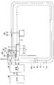
- FIG. 2 is a diagram schematically illustrating a configuration example around the window glass of the vehicle in which the antenna system 1 according to the first embodiment of the present invention is installed, and illustrates the case where the window glass 60 is a windshield. .
- FIG. 2 is an in-vehicle view as seen from the inside of the vehicle.
- the antenna system 1 includes a first antenna 10 and a second antenna 20 provided on a window glass 60, and a synthesis amplifier 50 that is an example of a cancel device 30, and is connected to a radio 40.
- the window glass 60 is attached to a body flange 71 formed on the body 70 of the vehicle.
- a peripheral edge 60a of the window glass 60 is illustrated by a dotted line in FIG.
- the body flange 71 is a window frame that surrounds the window opening, and has a flange end 71a that forms the window frame end.
- An alternate long and short dash line inside the flange 71 a indicates an inner edge of the shielding portion 61 provided on the window glass 60.
- the vehicle body 70 is described on the assumption that it is made of metal, but it may be made of other materials.
- an insulating material such as resin or carbon may be used.
- the noise source 90 includes a noise generator 91 and an output cable 92 connected to the noise generator 91.
- the noise generator 91 is attached to the surface of the window glass 60 via a bracket.
- the noise generator 91 is connected to one end of the output cable 92, and the other end of the output cable 92 is connected to an electronic circuit (not shown) or the like. It is connected.
- the place where the noise generator 91 is provided is not limited to this embodiment, and may be installed in the vicinity of the window glass 60.
- the vicinity of the window glass 60 may be provided around the opening of the vehicle body, or may be provided in a ceiling portion of the vehicle body.
- the noise in the frequency band within the 150 kHz to 300 MHz band is emitted from the noise source 90 radially. Therefore, the noise attenuates as the distance from the noise source 90 increases under the same conditions. Due to this property, when the antenna having the same shape is used, the antenna closer to the noise source 90 receives the noise more strongly.
- the waveform of the generated noise and the intensity of the radiated noise differ between the noise generator 91 and the output cable 92. That is, in FIG. 2, the noise generator 91 and the output cable 92 are independent noise sources.
- the output cable 92 is not always a noise source.
- the noise source is only the noise generator 91.
- the first antenna 10 has a first feeding point 15 provided at the upper corner of the window glass 60 and a first antenna conductor 17 extending from the first feeding point 15.
- the first antenna 10 has an AM broadcast wave band equal to or higher than a predetermined reception voltage in a state where noise in the same frequency band as the AM broadcast wave from the noise source 90 in the vehicle is mixed with the radio wave of the AM broadcast wave band coming from outside the vehicle. Are output from the first feeding point 15. Further, the first antenna 10 may be disposed at any position on the window glass 60.
- the first antenna conductor 17 is a linear conductor extending on the surface of the window glass 60 or in the window glass 60 and includes antenna elements 11, 12, 13, and 14.
- the antenna element 11 connected to the first feeding point 15 extends horizontally in the concealment film 61 on the top of the window glass 60
- the antenna element 12 connects to the antenna element 11 and extends vertically.
- the antenna element 13 is connected to the antenna element 12 and extends horizontally along the concealment film 61 where there is no concealment film 61
- the antenna element 14 is connected to the antenna element 13 and extends vertically.
- the AM broadcast wave reception performance at the antenna tends to increase as the conductor length is longer and the distance from the feeding point is longer, regardless of the shape of the antenna.
- the shape is not particularly limited to this embodiment, and it is sufficient that the conductor length that can receive AM broadcast waves and the direction away from the feeding point are extended.
- the second antenna 20 has a second feeding point 23 provided on the upper side of the window glass 60 and a second antenna conductor 25 extending from the second feeding point 23. Since the second antenna 20 is provided on the window glass provided with the first antenna 10, the second antenna conductor 25 is connected to the AM broadcast wave from the outside of the vehicle, the noise generator 91, and the output cable 92. Both the AM broadcast wave band and noise in the same frequency band are received, and the received signal is output from the second feeding point 23.
- the conductor length L2 of the second antenna conductor 25 is shorter than the conductor length L1 of the first antenna conductor 17.
- the longer the conductor length of the antenna conductor the higher the reception performance of each signal. Therefore, by configuring in this way, radio wave and noise in the AM broadcast wave band. It is possible to make it more difficult for the first antenna 10 to receive noise from the source 90.
- the difference in reception voltage with respect to the AM broadcast wave band between the first antenna 10 and the second antenna 20 is preferably 5 dB or more. .
- the conductor length of the second antenna conductor 25 is desirably 50% or less of the conductor length of the first antenna conductor 17. Details of the conductor lengths of the first antenna conductor 17 and the second antenna conductor 25 will be described later.
- the second antenna 20 can be disposed closer to the vehicle body 70 (body flange 71) than the first antenna 10 to reduce the output of signals obtained from AM broadcast waves and noise sources. Specifically, it is desirable that the closest distance L20 between the second antenna 20 and the flange end 71a in FIG. 2 be shorter than the closest distance L10 between the first antenna 10 and the flange end 71a.
- the second antenna 20 is installed at a position closer to the noise generating device 91 than the first antenna 10.
- the closest distance L4 between the second antenna conductor 25 and the noise generating device 91 is shorter than the closest distance L3 between the first antenna conductor 17 and the noise generating device 91 (L4 ⁇ L3).
- L4 is 80% or less of L3, more preferably 50% or less, and still more preferably 20% or less.
- the second antenna 20 is installed at a position closer to the noise generating device 91 than the first antenna 10, so that the noise is easily received from the noise generating device 91.
- the second antenna 20 is disposed at a position within 210 mm, preferably within 180 mm, more preferably within 150 mm, and even more preferably within 100 mm from the noise generating device 91, and satisfies the relationship between L3 and L4. It is desirable to do.
- the second antenna conductor 25 has a linear conductor 21 that extends on the surface of the window glass 60 or in the window glass 60, and includes a widened portion 22 that is wider than the linear conductor 21. Providing such a widened portion 22 makes it easy to receive noise from the noise generating device 91 without substantially changing the reception sensitivity of the AM broadcast wave depending on the conductor length. Further, by adjusting the size of the widened portion 22, it is possible to adjust the intensity of received noise.
- the reception gain of the AM broadcast wave received by the second antenna 20 is sufficiently lower than the reception gain of the AM broadcast wave received by the first antenna 10, and is received by the first antenna 10.
- the output of the received noise and the output of the noise received by the second antenna 20 can be adjusted to be equal.
- the reception voltage is adjusted by a canceling device such as a synthesis amplifier, which will be described later, so that the AM of the second antenna 20 is more than the first antenna 10.
- the voltage of the broadcast wave signal is low, and the noise signal voltage of the first antenna 10 and the second antenna 20 may be adjusted to be equal.
- the second antenna 20 when noise is also generated from the output cable 92, it is preferable to position the second antenna 20 so as to overlap the output cable 92 in plan view as shown in FIG. In this way, the second antenna 20 is installed so as to overlap the output cable 92 in plan view, and the distance between the second antenna 20 and the output cable 92 is closer than the distance between the first antenna 10 and the output cable 92. You may adjust it. Further, in FIG. 2, the widened portion 22 of the second antenna 20 is provided so as to overlap the output cable 92 in plan view. With such a configuration, it is possible to make it easier to receive the noise generated by the output cable 92.
- the first feeding point 15 and the second feeding point 23 connect the first antenna conductor 17 and the second antenna conductor 25 to the terminals 51 and 52 of the synthesis amplifier 50 through the conductive members 16 and 24. It is a feeding point for.
- the first feeding point 15 and the second feeding point 23 are preferably provided in the vicinity of the body flange 71 when the window glass 60 is attached to the body flange 71.
- the first feeding point 15 and the second feeding point 23 are unipolar, but may be bipolar having two feeding parts.
- a feed line such as an AV line or a coaxial cable is used.
- the inner conductor of the coaxial cable may be electrically connected to the feeding points 15 and 23 and the outer conductor of the coaxial cable may be connected to the vehicle body 70 with ground.
- a connector for electrically connecting to the first feeding point 15 and the second feeding point 23 may be installed at the first feeding point 15 and the second feeding point 23. With such a connector, it becomes easy to attach the inner conductor of the AV line or the coaxial cable to the first feeding point 15 and the second feeding point 23. Furthermore, a configuration in which a signal processing circuit such as an amplifier is mounted on the connector may be employed. Further, a protruding conductive member is installed at the first feeding point 15 and the second feeding point 23, and the protruding conductive member is connected to a connection portion provided on the body flange 71 to which the window glass 60 is attached. It is good also as a structure which contacts and fits.
- the shape of the first feeding point 15 and the second feeding point 23 may be determined according to the shape of the mounting surface of the conductive member or connector.
- a square shape or a polygonal shape such as a square, a substantially square, a rectangle, or a substantially rectangle is preferable for mounting. It may be a circle such as a circle, a substantially circle, an ellipse, or a substantially ellipse.
- the first antenna conductor 17, the second antenna conductor 25, the first feeding point 15, and the second feeding point 23 are made of a paste containing conductive metal, such as silver paste, on the inside of the window glass 60. It is formed by printing on the surface and baking.
- the present invention is not limited to this method, and a linear body or a foil-like body made of a conductive material such as copper may be formed on the vehicle inner surface or the vehicle outer surface of the window glass 60. It may be affixed with an adhesive or the like, and may be provided inside the window glass 60 itself.
- FIG. Furthermore, it is good also as a glass antenna by forming the flexible circuit board in which the antenna conductor was formed in the vehicle inner surface or the vehicle outer surface of the window glass 60.
- a concealing film 61 may be formed on the surface of the window glass 60, and a feeding point and a part or the whole of the antenna conductor may be provided on the concealing film 61.
- the concealing film 61 may be a ceramic such as a black ceramic film. In this case, when viewed from the outside of the window glass 60, the first antenna conductor 17, the second antenna conductor 25, the first feeding point 15, and the second antenna provided on the shielding film 61 by the shielding film 61. At least a part of the feeding point 23 becomes invisible from the outside of the vehicle. Therefore, the window glass 60 is excellent in design.
- the synthesis amplifier 50 is an example of a cancel device 30 that cancels the noise signal of the second antenna 20 from the reception signal of the first antenna 10.
- the synthesis amplifier 50 outputs the reception signal obtained by removing the noise signal of the second antenna 20 from the reception signal of the first antenna 10 to the radio 40 via the terminal 53.
- FIG. 3 is a diagram illustrating a first configuration example of the synthesis amplifier 50.
- the synthesis amplifier 50 in the figure is a cancel device having an AM amplifier (AM Amp) 55, an AM amplifier 54, and a phase inverter 57, and the noise signal of the second antenna 20 is received from the received signal of the first antenna 10. Cancel by phase inverter 57.
- AM Amp AM Amp
- AM amplifier 54 AM amplifier
- phase inverter 57 the noise signal of the second antenna 20 is received from the received signal of the first antenna 10. Cancel by phase inverter 57.
- the AM amplifier 55 amplifies and outputs the reception signal of the first antenna 10 input from the terminal 52.
- the AM amplifier 54 amplifies and outputs the noise signal of the second antenna 20 input from the terminal 51.
- the phase inverter 57 outputs a signal obtained by inverting the phase of the output signal of the AM amplifier 54 by 180 °.
- the synthesis amplifier 50 outputs a signal obtained by synthesizing the output signal of the AM amplifier 55 and the output signal of the phase inverter 57 from the terminal 53 to the radio 40 as a synthesis signal.
- the synthesis amplifier 50 may include an FM amplifier (FM Amp) 56.
- FM amplifier 56 amplifies the reception signal received by the first antenna 10 input from the terminal 52, and outputs the amplified signal from the terminal 53 to the radio 40 as a combined signal.
- FIG. 4 is a diagram illustrating a second configuration example of the synthesis amplifier 50. A description of the same configuration as that described above is omitted.
- the synthesis amplifier 50 in this figure is a cancel device having an AM amplifier 55, an AM amplifier 54, and a differential amplifier (Diff Amp) 58, and the noise signal of the second antenna 20 is received from the received signal of the first antenna 10. Canceled by the differential amplifier 58.
- Diff Amp differential amplifier
- the differential amplifier 58 amplifies the voltage difference between the output signal of the AM amplifier 55 and the output signal of the AM amplifier 54 and outputs the amplified signal from the terminal 53 to the radio 40.
- the differential amplifier 58 outputs a signal from which the noise signal component of the first antenna 10 has been removed by the differential amplification function as a combined signal.
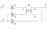
- FIG. 5 is a diagram illustrating a third configuration example of the synthesis amplifier 50. A description of the same configuration as that described above is omitted.
- the synthesis amplifier 50 in this figure is a cancel device having an AM amplifier 55, an AM amplifier 54, and a transformer 80. The noise signal of the second antenna 20 is canceled by the transformer 80 from the received signal of the first antenna 10.
- the transformer 80 is a transformer having a primary side coil 81 and a secondary side coil 82.
- the primary side coil 81 is connected to the first feeding point 15 of the first antenna 10 via one terminal 52 and the AM amplifier 55 and to the second feeding point 23 of the second antenna 20. And the other end connected through the terminal 51 and the AM amplifier 54.
- the secondary coil 82 has one end connected to the radio 40 via the terminal 53 and the other end connected to the ground.
- the reception signal of the first antenna 10 is input to one end of the primary side coil 81, and the noise signal of the second antenna 20 is input to the other end of the primary side coil 81.
- the signal from which the noise signal component of the second antenna 20 is removed can be output from the secondary coil 82 as a composite signal.
- FIG. 6 is a diagram illustrating a fourth configuration example of the synthesis amplifier 50. A description of the same configuration as that described above is omitted.
- the synthesis amplifier 50 in the figure is a cancel device having an AM amplifier 55, an AM amplifier 54, and a transformer 84, and cancels the noise signal of the second antenna 20 from the received signal of the first antenna 10 by the transformer 84.
- the transformer 84 in FIG. 6 can output the signal from which the noise signal component of the second antenna 20 is removed from the secondary coil 82 as a composite signal, as in FIG. 6 has a center tap 83 connected to the intermediate portion of the primary coil 81, and the center tap 83 is connected to the ground.
- the transformer 84 of this figure can be used for balanced-unbalanced conversion, and can be easily connected to the radio 40 from the terminal 53 via an unbalanced line such as a coaxial cable.
- the noise reception performance of the second antenna 20 is the same as the noise reception performance of the first antenna 10 by devising the shape and arrangement of the antenna without adjustment by the synthesis amplifier 50. It can comprise so that it may become substantially equal. That is, the noise output from the second antenna 20 is adjusted so as to have the same output level as the noise output from the first antenna 10. Accordingly, the voltage (noise voltage) of the noise signal mixed in the reception signal output from the first feeding point 15 of the first antenna 10 and the reception output from the second feeding point 23 of the second antenna 20. The noise voltage of the signal can be brought close to a substantially equal value.
- the synthesis amplifier 50 synthesizes the reception signal of the first antenna 10 and the reception signal of the second antenna 20, the amount of adjustment of the noise voltage can be minimized or eliminated.
- Such a configuration of the canceling device 30 can be simplified.
- a good noise canceling state can be achieved by adjusting the noise voltage by adjusting the reception voltage of the synthesis amplifier 50. Can be created.
- FIG. 7 is a schematic view showing a configuration according to the second embodiment. As shown in FIG. 7, the same reference numerals as those in FIG. 2 are used for members having the same configuration as that of the first embodiment shown in FIG. A description of the same configurations as those of the first embodiment will be omitted.
- the output cable 93 of the noise source 90 is different from the first embodiment of FIG. More specifically, the output cable 92 of FIG. 2 extends in a direction away from the window frame, but in FIG. 7, the output cable 93 of the noise source 90 is extended along the window frame and approaches the first antenna 10.
- the noise source will be described as the noise generator 91 and the output cable 93. Since the noise generator 91 and the output cable 93 are independent noise sources, it is desirable that the second antenna 20 be installed at a position closer to each of the noise generator 91 and the output cable 93 than the first antenna 10.
- the closest proximity distance L6 between the second antenna conductor 25 and the output cable 93 is shorter than the closest distance L5 between the first antenna conductor 17 and the output cable 93 (L6 ⁇ L5).
- the distance L4 between the second antenna conductor 25 and the noise generator 91 is shorter than the closest distance L3 between the first antenna conductor 17 and the noise generator 91 (L4 ⁇ L3).
- L6 ⁇ L5 and L4 ⁇ L3 makes it easy for the second antenna 20A to receive noise from each of the noise generator 91 and the output cable 93.
- the output cable 93 does not always emit noise.
- the output cable 93 does not emit noise, it is not necessary to consider both L6 ⁇ L5 and L4 ⁇ L3 as shown in FIG. 7, and the noise is predominantly received from the noise generating device 91 that emits noise. Therefore, it is sufficient to satisfy only the relationship of L4 ⁇ L3. At this time, L6> L5 may be satisfied.
- FIG. 8 shows a modification of the second embodiment.
- the case where the intensity of noise radiated from the noise generating device 91 is negligibly lower than the noise radiated from the output cable 93 is shown.
- the output cable 93 becomes a dominant noise source with respect to the first antenna 10. Therefore, in FIG. 8, L6 ⁇ L5 and the second antenna 20 ⁇ / b> B is configured to easily receive noise from the output cable 93 that is a dominant noise source with respect to the first antenna 10.
- the distance between the second antenna 20B and the noise generator 91 may be longer than the distance between the first antenna 10 and the noise generator 91.
- the distance between the second antenna 20B and the dominant noise source is set to the first. It is desirable to make it shorter than the distance between one antenna 10 and the dominant noise source.
- the second antenna 20B may be provided not in the window glass 60 but in the vicinity of the window glass 60, for example, on the vehicle body 70.
- the vehicle body 70 is an insulator such as a resin
- the second antenna 20B is provided directly on the vehicle body 70.
- the vehicle body 70 is a conductor such as a metal
- a dielectric such as an adhesive layer is separated. Can be attached to a metal vehicle body.
- the 2nd antenna (20, 20A, 20B) showed the example arrange
- the second antenna 20B By providing the second antenna 20B in the vehicle body 70 in the vicinity of the window glass 60 in this manner, noise when there is a noise source at a position close to the window glass is reduced from the reception signal obtained by the first antenna to the outside.
- a composite signal of a broadcast wave with reduced noise can be output, and a second antenna can be provided at a position with low visibility, which is excellent in terms of aesthetics.
- Example 1 (Conductor length of the first antenna conductor 17 and the second antenna conductor 25) A description will be given of the result of actually measuring the antenna gain of a vehicle window glass provided with a glass antenna attached to an actual vehicle.
- the length of the conductor is more dominant than the antenna conductor pattern for receiving radio waves. Therefore, in this embodiment, the feeding point is provided at the upper corner of the window glass, and the lateral direction from the feeding point. The results when the antenna conductor is extended linearly are described below.
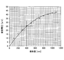
- FIG. 9A is a graph showing the relative relationship between the length of the antenna conductor and the antenna reception voltage. That is, FIG. 9A shows the measured value of the output voltage change with respect to the length of the conductor.
- the horizontal axis represents the measured value of the antenna conductor length (unit: mm), and the vertical axis represents the received voltage (unit: ⁇ V). Show.
- the reception gain of the antenna increases as the conductor length increases under the same conditions, and the antenna reception capability decreases. In this case, the reception gain is low. That is, since the antenna having a long conductor length has a large amplitude of the reception voltage, it is easy to receive both radio waves and noise in the AM broadcast band coming from outside the vehicle. On the other hand, an antenna with a short conductor length makes it difficult to receive radio waves and noise in the AM broadcast band coming from outside the vehicle due to the difference in gain.
- the antenna reception voltage is preferably 25 ⁇ V.
- the conductor length of the first antenna conductor 17 is required to be 400 mm or more.
- FIG. 9B is a diagram showing the correlation of the conductor length based on FIG. 9A so that the difference in received voltage between the first antenna 10 and the second antenna 20 is 5 dB.
- FIG. 9C is obtained by converting the conductor length of the second antenna conductor 25 of FIG. 9B to the ratio of the conductor length of the first antenna conductor 17.
- the conductor length of the first antenna conductor 17 is 400 mm, in order to obtain a difference in received voltage of 5 dB between the first antenna 10 and the second antenna 20, It can be seen that the conductor length of the second antenna conductor 25 may be 50% or less of the conductor length of the first antenna conductor 17.
- FIG. 10 shows a combined output of the first antenna 10 and the second antenna 20 when the conductor length of the first antenna conductor 17 is changed.
- the horizontal axis is the conductor length (unit: mm) of the first antenna conductor 17, the vertical axis is the combined AM gain (unit: dB ⁇ V), and the legend is the first antenna of the conductor length of the second antenna conductor 25. The ratio with respect to the conductor length of the conductor 17 is shown.
- the first antenna 10 and the second antenna 20 have the same distance from the noise source.
- the combined gain (gain) requires a combined gain of 20 dB ⁇ V as the minimum practical sensitivity.
- the minimum practical sensitivity of 20 dB ⁇ V is hardly exceeded. If it is 50% or less, a sensitivity of 20 dB ⁇ V or more can be obtained with no practical problem. Therefore, even when the combined gain is taken into consideration, the conductor length of the second antenna conductor 25 is preferably 50% or less of the conductor length of the first antenna conductor 17.
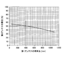
- ⁇ Example 2> (Distance between second antenna 20 and noise source 90)
- the similarity (correlation coefficient) of the noise waveform received by the first antenna 10 and the second antenna 20 and the intensity of the noise (electric field) are measured. did.
- the result is shown in FIG.
- the noise intensity when the distance L4 between the second antenna and the noise source 90 is 0 mm is expressed as 0 dB.
- FIG. 11 represents the distance (unit: mm) of the second antenna 20 from the noise source 90, and the vertical axis represents the correlation coefficient and the electric field of noise (unit: dB).
- the alternate long and short dash line indicates the correlation coefficient
- the solid line indicates the electric field.
- the correlation coefficient is less than 0.7 when the distance between the second antenna 20 and the noise source 90 is 320 mm or more. Since the correlation coefficient indicates the similarity of the noise waveform, if it is 0.7 or less, the effect of noise cancellation is reduced. Therefore, the correlation coefficient is preferably 0.7 or more. That is, from the viewpoint of the correlation coefficient, it can be seen that the distance between the second antenna 20 and the noise source 90 is preferably within 320 mm.
- the electric field is found to be less than ⁇ 15 dB when the distance from the second antenna 20 and the noise source 90 is 210 mm or more. Since the electric field indicates the intensity of noise, it is preferable that the electric field is ⁇ 15 dB or more so that the second antenna 20 receives noise equivalent to that of the first antenna 10.
- the distance between the second antenna 20 and the noise source 90 is within 210 mm, preferably within 180 mm, more preferably within 150 mm, and even more preferably within 100 mm. It is desirable that
- Example 3 (Effect of noise cancellation) A description will be given of the result of actually measuring the antenna gain by attaching the automobile window glass provided with the glass antenna of the first embodiment shown in FIG. 2 to an actual automobile. In the first embodiment shown in FIG. 2, the obtained antenna gain was measured. At that time, the dimensions of each part shown in FIG.
- Conductor length L1 1120 of the first antenna conductor (11 + 12 + 13 + 14)
- Conductor length L2 of the second antenna conductor 40 Area of widened portion 22 of second antenna conductor: 12 ⁇ 20
- Distance L10 20 between first antenna 10 and body flange 71
- Distance L20 20 between second antenna 20 and body flange 71 It was.
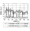
- FIG. 12A shows the waveform of the reception voltage received by the first antenna 10 for the radio wave flying from outside the vehicle
- FIG. 12B shows the waveform of the reception voltage received by the second antenna 20 for the radio wave flying from outside the vehicle.
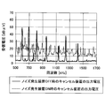
- FIG. 12C shows the waveform of the output voltage after adding them together using a cancel device. 12A to 12C, the horizontal axis represents frequency (unit: kHz), and the vertical axis represents reception voltage (unit: dB ⁇ V).
- the thick lines indicate the reception voltages of the first antenna 10 and the second antenna 20 when the noise source is turned off
- the thin lines indicate the first antenna 10 and the second antenna 20 when the noise source is turned on.
- the received voltage is shown.
- the state in which the noise source is turned off indicates that driving of the noise source is stopped and no signal is connected.
- the state where the noise source is turned on indicates a state where the noise source is driven and a signal is connected.
- the thick line indicates the output voltage of the cancel device when the noise source is turned off
- the dotted line indicates the output voltage of the cancel device when the noise source is turned on.
- the received broadcast wave spectrum clearly appears in FIGS. 12A to 12C.
- the reception voltage of the broadcast wave received by the second antenna 20 is lower than the reception voltage of the broadcast wave received by the first antenna 10.
- the value of the reception voltage of the broadcast wave of the first antenna 10 is 55 dB ⁇ V
- the value of the reception voltage of the broadcast wave of the second antenna 20 is about 40 dB ⁇ V.
- the second antenna 20 receives broadcast waves on average 15 dB ⁇ V lower than the first antenna 10.
- the noise signal waveform (other than the specific peak of the broadcast radio wave) depends on the reception voltage received by the second antenna 20 and the reception voltage received by the first antenna 10 shown in FIG. ) Is almost unchanged.
- FIG. 12C shows a synthesized voltage waveform based on the voltages in FIGS. 12A and 12B.
- the value of the noise output voltage when the noise generator 91 is turned on is greatly reduced by combining the signals.
- the noise level after synthesis can be reduced by about 20 dB ⁇ V as an average value, and the effect of noise cancellation is obtained.
- the distance L4 between the second antenna 20 and the noise generating device 91 was 33% of the distance L3 between the first antenna 10 and the noise generating device 91.
- the reception gain of the AM broadcast wave received by the second antenna 20 is compared with the reception gain of the AM broadcast wave received by the first antenna 10.
- the output of noise received by the first antenna 10 and the output of noise received by the second antenna 20 can be adjusted to be equal.
- the antenna system of the present invention when there is a noise source at a position close to the broadcast wave antenna, it is possible to suppress a decrease in the reception performance of the broadcast wave received by the broadcast wave antenna.
- the present invention is, for example, particularly a long wave broadcast band (LW band) (150 to 280 kHz), an AM broadcast band (MW band) (520 to 1700 kHz), a short wave broadcast band (SW band) (2.3 to 26.1 MHz), FM broadcast band in Japan (76-90MHz), FM broadcast band in the US (88-108MHz), TV VHF band (90-108MHz, 170-222MHz), TV VHF band in North America and Europe (45-86MHz, 175-225MHz) ) And band III band (174-240 MHz) of digital audio broadcasting (Digital Audio Broadcasting: DAB).
- LW band long wave broadcast band
- AM broadcast band MW band
- SW band 2.3 to 26.1 MHz
- FM broadcast band in Japan 76-90MHz
- FM broadcast band in the US 88-108MHz
- TV VHF band 90-108MHz, 170-222MHz
- TV VHF band in North America and Europe 45-86MHz, 175-225MHz
- band III band 174-240 MHz
Landscapes
- Engineering & Computer Science (AREA)
- Computer Networks & Wireless Communication (AREA)
- Signal Processing (AREA)
- Details Of Aerials (AREA)
- Noise Elimination (AREA)
Abstract
Description
第1のアンテナ導体と第1の給電点とを有し、所定の周波数帯の放送波を受信する第1アンテナと、
第2のアンテナ導体と第2の給電点とを有し、ノイズ源からのノイズを受信する第2アンテナと、
前記第1アンテナで受信された受信信号から前記第2アンテナで受信されたノイズ信号をキャンセルするキャンセル装置と、を有し、
前記所定の周波数帯の放送波の電波が同等に到達する位置に、前記第1アンテナと前記第2アンテナを設け、
前記第2アンテナで受信された前記所定の周波数帯の受信利得は、前記第1アンテナで受信された前記所定の周波数帯の受信利得よりも低く、前記第1アンテナで受信されたノイズの出力と前記第2アンテナで受信されたノイズの出力とが同等になるように調整される、アンテナシステムが提供される。
以下、図面を参照しながら、本発明を実施するための形態の説明を行う。なお、形態を説明するための図面において、方向について特に記載のない場合には図面上での方向をいうものとし、各図面の基準の方向は、記号、数字の方向に対応する。また、平行、直角などの方向は、本発明の効果を損なわない程度のズレを許容するものである。また、本発明が適用可能な窓ガラスとして、例えば、車両の前部に取り付けられるフロントガラス、車両の後部に取り付けられるリヤガラス、車両のサイド部に取り付けられるサイドガラス、車両の天井部に取り付けられるルーフガラスなどが挙げられる。
図7は第2実施形態に係る構成を示した概略図である。図7に示すように、前述した図2に示した第1実施形態と同様の構成を有する部材については、図2の参照符号と同様の参照符号が使用されている。それら第1実施形態と同様の構成については説明を省略する。
図8に第2実施形態の変形例を示す。第2の実施形態の変形例では、ノイズ発生装置91から放射されるノイズの強度が出力ケーブル93から放射されるノイズと比べて無視できるほど低い場合を示す。このような場合、出力ケーブル93が第1アンテナ10に対して支配的なノイズ源となる。したがって、図8ではL6<L5として、第2アンテナ20Bが、第1アンテナ10に対して支配的なノイズ源である出力ケーブル93からのノイズを受け易い構成としている。この際、第2アンテナ20Bとノイズ発生装置91との距離は第1アンテナ10とノイズ発生装置91との距離よりも長くても良い。このように、ノイズ発生装置91と出力ケーブル93とのノイズの発生強度に差があり、いずれかが支配的なノイズ源となる場合、第2アンテナ20Bと支配的なノイズ源との距離を第1アンテナ10と支配的なノイズ源との距離よりも短くすることが望ましい。
<実施例1>
(第1のアンテナ導体17と第2のアンテナ導体25の導体長)
ガラスアンテナが設けられた自動車用窓ガラスを実際の自動車に取り付けて、そのアンテナ利得を実測した結果について説明する。
(第2アンテナ20とノイズ源90との距離)
第2アンテナ20とノイズ源との距離を変化させたとき、第1アンテナ10と第2アンテナ20との受信するノイズの波形の相似性(相関係数)及びノイズの強度(電界)をそれぞれ測定した。その結果を図11に示す。なお、本実施例では、第2アンテナとノイズ源90との距離L4が0mmの時のノイズの強度を0dBとして表記している。
(ノイズキャンセルの効果)
図2で示した第1実施形態のガラスアンテナが設けられた自動車用窓ガラスを実際の自動車に取り付けて、そのアンテナ利得を実測した結果について説明する。図2で示した第1実施形態において、得られるアンテナ利得を測定した。その際の図2に示した各部の寸法は、単位をmmとすると、
第1のアンテナ導体(11+12+13+14)の導体長L1:1120
第2のアンテナ導体の導体長L2:40
第2のアンテナ導体の拡幅部22の面積:12x20
第1アンテナ10とノイズ発生装置91との距離L3:84
第2アンテナ20とノイズ発生装置91との距離L4:28
第1アンテナ10とボディフランジ71との距離L10:20
第2アンテナ20とボディフランジ71との距離L20:20
とした。
10 第1アンテナ
11、12、13、14 アンテナエレメント
15 第1の給電点
16、24 導電性部材
17 第1のアンテナ導体
20、20A、20B 第2アンテナ
21 線状導体
22 拡幅部
23 第2の給電点
25 第2のアンテナ導体
30 キャンセル装置
31 位相反転器
32 加算器
40 ラジオ
50 合成アンプ
51、52、53 端子
54、55 AMアンプ
56 FMアンプ
57 位相反転器
58 差動増幅器
60 窓ガラス
61 隠蔽膜
70 車両ボディ
71 ボディフランジ
80、84 トランス
81 1次側コイル
82 2次側コイル
90 ノイズ源
91 ノイズ発生装置
92、93 出力ケーブル
L1 第1のアンテナ導体の導体長
L2 第2のアンテナ導体の導体長
L3 ノイズ発生装置と第1のアンテナ導体との最近接距離
L4 ノイズ発生装置と第1のアンテナ導体との最近接距離
L5 出力ケーブルと第1のアンテナ導体との最近接距離
L6 出力ケーブルと第2のアンテナ導体との最近接距離
L10 第1アンテナ10からボディフランジの基準線の距離
L20 第2アンテナ20からボディフランジの基準線の距離
Claims (14)
- 第1のアンテナ導体と第1の給電点とを有し、所定の周波数帯の放送波を受信する第1アンテナと、
第2のアンテナ導体と第2の給電点とを有し、ノイズ源からのノイズを受信する第2アンテナと、
前記第1アンテナで受信された受信信号から前記第2アンテナで受信されたノイズ信号をキャンセルするキャンセル装置と、を有し、
前記所定の周波数帯の放送波の電波が同等に到達する位置に、前記第1アンテナと前記第2アンテナを設け、
前記第2アンテナで受信された前記所定の周波数帯の受信利得は、前記第1アンテナで受信された前記所定の周波数帯の受信利得よりも低く、前記第1アンテナで受信されたノイズの出力と前記第2アンテナで受信されたノイズの出力とが同等になるように調整される、アンテナシステム。 - 前記第1アンテナと前記第2アンテナは、車両のボディに形成された窓開口部に設置された窓ガラスに設けられ、
前記ノイズ源は、前記窓ガラスの近傍に設けられる、請求項1に記載のアンテナシステム。 - 前記第2アンテナは、前記第1アンテナよりも前記ボディに近い位置に設けられている、請求項2に記載のアンテナシステム。
- 前記第2のアンテナ導体の導体長は、前記第1のアンテナ導体の導体長よりも短い、請求項1~3のいずれか1項に記載のアンテナシステム。
- 前記第2のアンテナ導体の導体長は、前記第1のアンテナ導体の導体長の50%以下である、請求項4に記載のアンテナシステム。
- 前記第2アンテナの前記受信利得が前記第1アンテナの前記受信利得よりも5dB以上低い、請求項1~5のいずれか1項に記載のアンテナシステム。
- 前記第2アンテナは、前記第1アンテナよりも前記ノイズ源に近い位置に設置されている、請求項1~6のいずれか1項に記載のアンテナシステム。
- 前記ノイズ源は、ノイズ発生装置を有し、
前記第2アンテナは、前記第1アンテナよりも前記ノイズ発生装置に近い位置に設置されている、請求項7に記載のアンテナシステム。 - 前記ノイズ源は、出力ケーブルを有し、
前記第2アンテナは、前記第1アンテナよりも前記出力ケーブルに近い位置に設置されている、請求項7又は8に記載のアンテナシステム。 - 前記第2アンテナは、前記出力ケーブルと平面視で重なる位置にある、請求項9に記載のアンテナシステム。
- 前記第2のアンテナ導体は、線幅が太い部分と細い部分を含む、請求項1~10のいずれか1項に記載のアンテナシステム。
- 前記キャンセル装置が、前記第1アンテナの前記受信信号と前記第2アンテナの前記受信信号の少なくとも一方を制御することで、
前記第1アンテナで受信されたノイズの出力と前記第2アンテナで受信されたノイズの出力とが同等になるように調整される、請求項1~11のいずれか1項に記載のアンテナシステム。 - 前記キャンセル装置は、前記第1アンテナから出力された放送波の信号及びノイズと、位相を反転させた前記第2アンテナから出力された放送波の信号及びノイズと、を合成させることで、外部へノイズが減少した放送波の合成信号を出力する、請求項1~12のいずれか1項に記載のアンテナシステム。
- 前記所定の周波数帯は、150kHz以上300MHz以下に含まれる帯域である、請求項1~13のいずれか1項に記載のアンテナシステム。
Priority Applications (4)
| Application Number | Priority Date | Filing Date | Title |
|---|---|---|---|
| EP14872944.5A EP3086476B8 (en) | 2013-12-20 | 2014-12-16 | Antenna system |
| CN201480066367.1A CN105814802A (zh) | 2013-12-20 | 2014-12-16 | 天线系统 |
| JP2015553558A JP6418168B2 (ja) | 2013-12-20 | 2014-12-16 | アンテナシステム |
| US15/165,072 US9882589B2 (en) | 2013-12-20 | 2016-05-26 | Antenna system |
Applications Claiming Priority (2)
| Application Number | Priority Date | Filing Date | Title |
|---|---|---|---|
| JP2013-264510 | 2013-12-20 | ||
| JP2013264510 | 2013-12-20 |
Related Child Applications (1)
| Application Number | Title | Priority Date | Filing Date |
|---|---|---|---|
| US15/165,072 Continuation US9882589B2 (en) | 2013-12-20 | 2016-05-26 | Antenna system |
Publications (1)
| Publication Number | Publication Date |
|---|---|
| WO2015093490A1 true WO2015093490A1 (ja) | 2015-06-25 |
Family
ID=53402835
Family Applications (1)
| Application Number | Title | Priority Date | Filing Date |
|---|---|---|---|
| PCT/JP2014/083296 WO2015093490A1 (ja) | 2013-12-20 | 2014-12-16 | アンテナシステム |
Country Status (5)
| Country | Link |
|---|---|
| US (1) | US9882589B2 (ja) |
| EP (1) | EP3086476B8 (ja) |
| JP (1) | JP6418168B2 (ja) |
| CN (1) | CN105814802A (ja) |
| WO (1) | WO2015093490A1 (ja) |
Cited By (1)
| Publication number | Priority date | Publication date | Assignee | Title |
|---|---|---|---|---|
| JP2017175290A (ja) * | 2016-03-22 | 2017-09-28 | 旭硝子株式会社 | バックドア、及びガラスアンテナ |
Families Citing this family (5)
| Publication number | Priority date | Publication date | Assignee | Title |
|---|---|---|---|---|
| DE102017206480B3 (de) | 2017-04-18 | 2018-06-14 | Audi Ag | Verfahren zum Betreiben eines kapazitiven Regensensors eines Kraftfahrzeugs, Messsignalentstörungsvorrichtung und Kraftfahrzeug mit einer derartigen Messsignalentstörungsvorrichtung |
| US20190190555A1 (en) * | 2017-12-18 | 2019-06-20 | Government of the United States, as epresented by the Secretary of the Air Force | Very low frequency noise cancellation receiver system |
| EP3771030A4 (en) * | 2018-03-22 | 2021-12-08 | Central Glass Company, Limited | GLASS WINDOWS FOR VEHICLE |
| JPWO2020203875A1 (ja) * | 2019-03-29 | 2020-10-08 | ||
| DE102019114883B3 (de) * | 2019-06-03 | 2020-08-13 | Fujikura Technology Europe GmbH | Radarantennenanordnung für ein Fahrzeug, Fahrzeug und Verfahren zur Fertigung einer Radarantennenanordnung |
Citations (3)
| Publication number | Priority date | Publication date | Assignee | Title |
|---|---|---|---|---|
| JPH04280125A (ja) * | 1991-03-07 | 1992-10-06 | Asahi Glass Co Ltd | ガラスアンテナ |
| JP2012257155A (ja) * | 2011-06-10 | 2012-12-27 | Toyota Motor Corp | アンテナシステム |
| JP2013168744A (ja) | 2012-02-14 | 2013-08-29 | Denso Corp | 車載受信機 |
Family Cites Families (6)
| Publication number | Priority date | Publication date | Assignee | Title |
|---|---|---|---|---|
| JP2009164678A (ja) * | 2007-12-28 | 2009-07-23 | Central Glass Co Ltd | 車両用ガラスアンテナ |
| JP4941338B2 (ja) * | 2008-02-01 | 2012-05-30 | 富士通株式会社 | 通信装置、ノイズ除去方法及びコンピュータプログラム |
| JP5029439B2 (ja) * | 2008-03-14 | 2012-09-19 | 富士通株式会社 | 無線通信装置及び干渉除去方法 |
| EP2214254A4 (en) * | 2008-09-16 | 2010-10-27 | Central Glass Co Ltd | GLASS ANTENNA FOR VEHICLE |
| JP2010272997A (ja) * | 2009-05-20 | 2010-12-02 | Sanyo Electric Co Ltd | 受信装置 |
| JP5842140B2 (ja) * | 2010-03-18 | 2016-01-13 | パナソニックIpマネジメント株式会社 | 車載用ラジオ受信装置およびノイズキャンセル方法 |
-
2014
- 2014-12-16 EP EP14872944.5A patent/EP3086476B8/en not_active Not-in-force
- 2014-12-16 JP JP2015553558A patent/JP6418168B2/ja active Active
- 2014-12-16 CN CN201480066367.1A patent/CN105814802A/zh active Pending
- 2014-12-16 WO PCT/JP2014/083296 patent/WO2015093490A1/ja active Application Filing
-
2016
- 2016-05-26 US US15/165,072 patent/US9882589B2/en active Active
Patent Citations (3)
| Publication number | Priority date | Publication date | Assignee | Title |
|---|---|---|---|---|
| JPH04280125A (ja) * | 1991-03-07 | 1992-10-06 | Asahi Glass Co Ltd | ガラスアンテナ |
| JP2012257155A (ja) * | 2011-06-10 | 2012-12-27 | Toyota Motor Corp | アンテナシステム |
| JP2013168744A (ja) | 2012-02-14 | 2013-08-29 | Denso Corp | 車載受信機 |
Cited By (2)
| Publication number | Priority date | Publication date | Assignee | Title |
|---|---|---|---|---|
| JP2017175290A (ja) * | 2016-03-22 | 2017-09-28 | 旭硝子株式会社 | バックドア、及びガラスアンテナ |
| US10686245B2 (en) | 2016-03-22 | 2020-06-16 | AGC Inc. | Back door, and glass antenna |
Also Published As
| Publication number | Publication date |
|---|---|
| EP3086476B1 (en) | 2019-06-12 |
| EP3086476A4 (en) | 2017-08-16 |
| US9882589B2 (en) | 2018-01-30 |
| JP6418168B2 (ja) | 2018-11-07 |
| JPWO2015093490A1 (ja) | 2017-03-16 |
| US20160269059A1 (en) | 2016-09-15 |
| EP3086476B8 (en) | 2019-07-24 |
| EP3086476A1 (en) | 2016-10-26 |
| CN105814802A (zh) | 2016-07-27 |
Similar Documents
| Publication | Publication Date | Title |
|---|---|---|
| JP6418168B2 (ja) | アンテナシステム | |
| JP5153300B2 (ja) | アンテナ | |
| EP3101734B1 (en) | Glass antenna | |
| US10181636B2 (en) | Antenna system | |
| JP2013026697A (ja) | ガラスアンテナ及び窓ガラス | |
| JP6436159B2 (ja) | ガラスアンテナ及びアンテナを備える窓ガラス | |
| JP2010114782A (ja) | 車両用ガラスアンテナ及び車両用窓ガラス | |
| EP2264827A1 (en) | Glass antenna and window glass for vehicle | |
| US20200373654A1 (en) | Antenna apparatus | |
| JP5003627B2 (ja) | 車両用ガラスアンテナ及び車両用窓ガラス | |
| US11962076B2 (en) | Antenna device | |
| JP2011049825A (ja) | 車両用受信設備 | |
| WO2020230696A1 (ja) | アンテナ装置 | |
| JP2009111704A (ja) | 車両用受信設備 | |
| JP6756868B2 (ja) | アンテナ装置 | |
| JP7015359B2 (ja) | アンテナ装置 | |
| JP5499810B2 (ja) | 車両用ガラスアンテナ及び車両用窓ガラス | |
| JP2013026800A (ja) | アンテナ装置 | |
| WO2009064003A1 (ja) | 車両用アンテナ装置 | |
| JP2023152289A (ja) | 車載用アンテナ装置 | |
| JP2005354176A (ja) | 車載用アンテナ | |
| JP2011182280A (ja) | 車載用アンテナシステム | |
| JP2008167189A (ja) | アンテナ装置、及び受信システム | |
| JP2010136079A (ja) | 自動車用ガラスアンテナ | |
| JP2002314314A (ja) | 自動車用窓ガラスアンテナ |
Legal Events
| Date | Code | Title | Description |
|---|---|---|---|
| 121 | Ep: the epo has been informed by wipo that ep was designated in this application |
Ref document number: 14872944 Country of ref document: EP Kind code of ref document: A1 |
|
| ENP | Entry into the national phase |
Ref document number: 2015553558 Country of ref document: JP Kind code of ref document: A |
|
| REEP | Request for entry into the european phase |
Ref document number: 2014872944 Country of ref document: EP |
|
| WWE | Wipo information: entry into national phase |
Ref document number: 2014872944 Country of ref document: EP |
|
| NENP | Non-entry into the national phase |
Ref country code: DE |