WO2015087690A1 - イオン液体を含む光波長変換要素およびその光波長変換要素を含む物品 - Google Patents
イオン液体を含む光波長変換要素およびその光波長変換要素を含む物品 Download PDFInfo
- Publication number
- WO2015087690A1 WO2015087690A1 PCT/JP2014/080937 JP2014080937W WO2015087690A1 WO 2015087690 A1 WO2015087690 A1 WO 2015087690A1 JP 2014080937 W JP2014080937 W JP 2014080937W WO 2015087690 A1 WO2015087690 A1 WO 2015087690A1
- Authority
- WO
- WIPO (PCT)
- Prior art keywords
- ionic liquid
- wavelength conversion
- conversion element
- light
- derivatives
- Prior art date
- Legal status (The legal status is an assumption and is not a legal conclusion. Google has not performed a legal analysis and makes no representation as to the accuracy of the status listed.)
- Ceased
Links
- 0 CC(*1*2(N)N)=C(C)C(C)=C1C(c1ccccc1)=C1*2=C(C)C=C1C Chemical compound CC(*1*2(N)N)=C(C)C(C)=C1C(c1ccccc1)=C1*2=C(C)C=C1C 0.000 description 1
Images









Classifications
-
- C—CHEMISTRY; METALLURGY
- C09—DYES; PAINTS; POLISHES; NATURAL RESINS; ADHESIVES; COMPOSITIONS NOT OTHERWISE PROVIDED FOR; APPLICATIONS OF MATERIALS NOT OTHERWISE PROVIDED FOR
- C09K—MATERIALS FOR MISCELLANEOUS APPLICATIONS, NOT PROVIDED FOR ELSEWHERE
- C09K11/00—Luminescent materials, e.g. electroluminescent or chemiluminescent
- C09K11/06—Luminescent materials, e.g. electroluminescent or chemiluminescent containing organic luminescent materials
-
- B—PERFORMING OPERATIONS; TRANSPORTING
- B01—PHYSICAL OR CHEMICAL PROCESSES OR APPARATUS IN GENERAL
- B01J—CHEMICAL OR PHYSICAL PROCESSES, e.g. CATALYSIS OR COLLOID CHEMISTRY; THEIR RELEVANT APPARATUS
- B01J31/00—Catalysts comprising hydrides, coordination complexes or organic compounds
- B01J31/02—Catalysts comprising hydrides, coordination complexes or organic compounds containing organic compounds or metal hydrides
-
- B—PERFORMING OPERATIONS; TRANSPORTING
- B01—PHYSICAL OR CHEMICAL PROCESSES OR APPARATUS IN GENERAL
- B01J—CHEMICAL OR PHYSICAL PROCESSES, e.g. CATALYSIS OR COLLOID CHEMISTRY; THEIR RELEVANT APPARATUS
- B01J31/00—Catalysts comprising hydrides, coordination complexes or organic compounds
- B01J31/02—Catalysts comprising hydrides, coordination complexes or organic compounds containing organic compounds or metal hydrides
- B01J31/0277—Catalysts comprising hydrides, coordination complexes or organic compounds containing organic compounds or metal hydrides comprising ionic liquids, as components in catalyst systems or catalysts per se, the ionic liquid compounds being used in the molten state at the respective reaction temperature
- B01J31/0278—Catalysts comprising hydrides, coordination complexes or organic compounds containing organic compounds or metal hydrides comprising ionic liquids, as components in catalyst systems or catalysts per se, the ionic liquid compounds being used in the molten state at the respective reaction temperature containing nitrogen as cationic centre
- B01J31/0285—Catalysts comprising hydrides, coordination complexes or organic compounds containing organic compounds or metal hydrides comprising ionic liquids, as components in catalyst systems or catalysts per se, the ionic liquid compounds being used in the molten state at the respective reaction temperature containing nitrogen as cationic centre also containing elements or functional groups covered by B01J31/0201 - B01J31/0274
-
- B—PERFORMING OPERATIONS; TRANSPORTING
- B01—PHYSICAL OR CHEMICAL PROCESSES OR APPARATUS IN GENERAL
- B01J—CHEMICAL OR PHYSICAL PROCESSES, e.g. CATALYSIS OR COLLOID CHEMISTRY; THEIR RELEVANT APPARATUS
- B01J31/00—Catalysts comprising hydrides, coordination complexes or organic compounds
- B01J31/16—Catalysts comprising hydrides, coordination complexes or organic compounds containing coordination complexes
- B01J31/22—Organic complexes
- B01J31/2282—Unsaturated compounds used as ligands
- B01J31/2295—Cyclic compounds, e.g. cyclopentadienyls
-
- B—PERFORMING OPERATIONS; TRANSPORTING
- B01—PHYSICAL OR CHEMICAL PROCESSES OR APPARATUS IN GENERAL
- B01J—CHEMICAL OR PHYSICAL PROCESSES, e.g. CATALYSIS OR COLLOID CHEMISTRY; THEIR RELEVANT APPARATUS
- B01J35/00—Catalysts, in general, characterised by their form or physical properties
- B01J35/30—Catalysts, in general, characterised by their form or physical properties characterised by their physical properties
- B01J35/39—Photocatalytic properties
-
- C—CHEMISTRY; METALLURGY
- C09—DYES; PAINTS; POLISHES; NATURAL RESINS; ADHESIVES; COMPOSITIONS NOT OTHERWISE PROVIDED FOR; APPLICATIONS OF MATERIALS NOT OTHERWISE PROVIDED FOR
- C09K—MATERIALS FOR MISCELLANEOUS APPLICATIONS, NOT PROVIDED FOR ELSEWHERE
- C09K11/00—Luminescent materials, e.g. electroluminescent or chemiluminescent
- C09K11/02—Use of particular materials as binders, particle coatings or suspension media therefor
- C09K11/025—Use of particular materials as binders, particle coatings or suspension media therefor non-luminescent particle coatings or suspension media
-
- G—PHYSICS
- G02—OPTICS
- G02B—OPTICAL ELEMENTS, SYSTEMS OR APPARATUS
- G02B5/00—Optical elements other than lenses
- G02B5/20—Filters
- G02B5/22—Absorbing filters
- G02B5/24—Liquid filters
-
- H—ELECTRICITY
- H10—SEMICONDUCTOR DEVICES; ELECTRIC SOLID-STATE DEVICES NOT OTHERWISE PROVIDED FOR
- H10F—INORGANIC SEMICONDUCTOR DEVICES SENSITIVE TO INFRARED RADIATION, LIGHT, ELECTROMAGNETIC RADIATION OF SHORTER WAVELENGTH OR CORPUSCULAR RADIATION
- H10F77/00—Constructional details of devices covered by this subclass
- H10F77/40—Optical elements or arrangements
- H10F77/42—Optical elements or arrangements directly associated or integrated with photovoltaic cells, e.g. light-reflecting means or light-concentrating means
- H10F77/45—Wavelength conversion means, e.g. by using luminescent material, fluorescent concentrators or up-conversion arrangements
-
- C—CHEMISTRY; METALLURGY
- C09—DYES; PAINTS; POLISHES; NATURAL RESINS; ADHESIVES; COMPOSITIONS NOT OTHERWISE PROVIDED FOR; APPLICATIONS OF MATERIALS NOT OTHERWISE PROVIDED FOR
- C09K—MATERIALS FOR MISCELLANEOUS APPLICATIONS, NOT PROVIDED FOR ELSEWHERE
- C09K2211/00—Chemical nature of organic luminescent or tenebrescent compounds
- C09K2211/10—Non-macromolecular compounds
- C09K2211/1003—Carbocyclic compounds
- C09K2211/1011—Condensed systems
-
- C—CHEMISTRY; METALLURGY
- C09—DYES; PAINTS; POLISHES; NATURAL RESINS; ADHESIVES; COMPOSITIONS NOT OTHERWISE PROVIDED FOR; APPLICATIONS OF MATERIALS NOT OTHERWISE PROVIDED FOR
- C09K—MATERIALS FOR MISCELLANEOUS APPLICATIONS, NOT PROVIDED FOR ELSEWHERE
- C09K2211/00—Chemical nature of organic luminescent or tenebrescent compounds
- C09K2211/18—Metal complexes
- C09K2211/185—Metal complexes of the platinum group, i.e. Os, Ir, Pt, Ru, Rh or Pd
-
- Y—GENERAL TAGGING OF NEW TECHNOLOGICAL DEVELOPMENTS; GENERAL TAGGING OF CROSS-SECTIONAL TECHNOLOGIES SPANNING OVER SEVERAL SECTIONS OF THE IPC; TECHNICAL SUBJECTS COVERED BY FORMER USPC CROSS-REFERENCE ART COLLECTIONS [XRACs] AND DIGESTS
- Y02—TECHNOLOGIES OR APPLICATIONS FOR MITIGATION OR ADAPTATION AGAINST CLIMATE CHANGE
- Y02E—REDUCTION OF GREENHOUSE GAS [GHG] EMISSIONS, RELATED TO ENERGY GENERATION, TRANSMISSION OR DISTRIBUTION
- Y02E10/00—Energy generation through renewable energy sources
- Y02E10/50—Photovoltaic [PV] energy
- Y02E10/52—PV systems with concentrators
Definitions
- the present invention relates to a light wavelength conversion element containing an ionic liquid and an article (a solar cell, a photocatalyst, a photocatalytic hydrogen / oxygen generator, and a light upconversion filter) including the light wavelength conversion element.
- Light-secondary energy conversion elements elements that convert light into secondary energy
- solar cells with high light-secondary energy conversion efficiency high light-secondary energy conversion efficiency
- hydrogen-generating photocatalysts Is growing.
- Light-secondary energy conversion elements such as general solar cells and hydrogen-generating photocatalysts have a certain threshold wavelength that is unique to the light-secondary energy conversion element among light in a wide wavelength range included in sunlight. Only short wavelength components are used for conversion, and components longer than the threshold wavelength are unused. Therefore, as one of the technologies for effectively using light in a wide wavelength range included in sunlight, light up-conversion (that is, light by absorbing light of a long wavelength and emitting light of a shorter wavelength) Are being studied.
- Patent Document 1 discloses a composition for up-converting photon energy, a first component that functions as a photoreceptor such as at least phthalocyanine, metal porphyrin, metal phthalocyanine, and absorbs energy in a first wavelength region, and polyfluorene. , Oligofluorenes and copolymers thereof, and a second component that functions as a light emitter such as polyparaphenylene and emits energy in a second wavelength region.
- a photoreceptor such as at least phthalocyanine, metal porphyrin, metal phthalocyanine
- a second component that functions as a light emitter such as polyparaphenylene and emits energy in a second wavelength region.
- Non-Patent Document 1 describes an optical up-converter using relatively weak light such as sunlight in a toluene solvent using a triplet-triplet annihilation process (hereinafter referred to as “TTA process”) in an organic molecule.
- TTA process triplet-triplet annihilation process
- Non-patent Documents 2 and 3 There are also precedents using high molecular weight organic polymers as the medium of organic molecules contained in the optical upconverter.
- Patent Document 2 discloses a triplet energy of the sensitizer in a system including at least one polymer for light upconversion and at least one sensitizer containing at least one heavy atom. Systems are described where the level is higher than the triplet energy level of the polymer.
- Non-Patent Document 2 describes an optical upconverter using a polymer of cellulose acetate (molecular weight: about 100,000) as a dispersion medium of organic molecules.
- Non-Patent Document 3 describes an optical up-converter using a soft rubber-like polymer as a medium at room temperature where the glass transition temperature (Tg) is 236 K (minus 37 ° C.).
- Non-Patent Document 4 describes an optical upconverter using a styrene oligomer (a mixture of styrene trimer and tetramer) as a medium for organic photosensitizing molecules and organic light emitting molecules.
- a styrene oligomer a mixture of styrene trimer and tetramer
- Non-Patent Document 5 describes metalloporphyrins as organic photosensitizing molecules that can be used for light upconversion using the TTA process, and diphenylanthracene, 9,10-bis (phenylethynyl) as organic light emitting molecules. ) Anthracene and 9,10-bis (phenylethynyl) naphthacene are described, and toluene is described as a medium for organic photosensitizer and organic light emitting molecules.
- Non-Patent Document 6 discloses that boron dipyrromethene (BODIPY) derivative is used as a sensitizer for photoupconversion using TTA process, and perylene or 1-chloro-9,10-bis (phenylethynyl) anthracene is used as a medium. It is described that toluene is used.
- BODIPY boron dipyrromethene
- Non-patent Document 1 In optical upconverters using the TTA process, in principle, it is necessary for organic molecules to exchange energy in a medium in order to exchange energy, so that most prior art (Non-patent Document 1) is required.
- a volatile organic solvent such as toluene or benzene or a highly volatile medium such as styrene oligomer was used as the medium.
- highly volatile media such as volatile organic solvents and styrene oligomers have a safety problem due to their flammability, and lightly absorb resin materials that dissolve in the media or swell due to penetration of the media. The problem is that it cannot be used as a container for wavelength conversion elements.
- optical up-converter (Patent Document 2 and Non-Patent Documents 2 and 3) using a TTA process using a polymer compound such as cellulose acetate and flexible rubber as a medium
- the polymer compound is flammable.
- it since it is solid at room temperature (300 K) and has low fluidity, there has been a problem that the intensity of the up-converted light is significantly reduced at room temperature (300 K) and below.
- optical up-conversion due to the TTA process is caused by the fact that organic molecules responsible for triplet excitation energy inside the medium need to exchange energy between organic molecules through diffusion motion and mutual collision.
- the upconversion emission intensity increases, but in the temperature range where the temperature is low and the fluidity of the medium is poor ( ⁇ 300K), the upconversion emission intensity. Is described to be very weak.
- the present inventors have proposed a light wavelength conversion element in which an organic photosensitizer molecule and an organic light emitting molecule are dissolved and / or dispersed in an ionic liquid in light upconversion using a TTA process.
- a decrease in upconversion light intensity due to high viscosity of the medium, flammability of the medium, and volatility of the medium are solved (Patent Document 3).
- optical wavelength conversion element that has higher optical wavelength conversion efficiency (up-conversion quantum efficiency) that can be applied to light as low as the intensity of sunlight.
- optical wavelength conversion element that has good temporal stability.
- the present invention has been made in view of the above-mentioned problems, and its purpose is to have high light wavelength conversion efficiency applicable to light as weak as the intensity of sunlight and to have good temporal stability, and therefore, the sun.
- the light wavelength conversion element of the present invention contains an organic photosensitizer molecule (A) and an organic light emitting molecule (B), which are a combination showing a TTA process, in an ionic liquid (C).
- a visual wavelength homogeneous and transparent light wavelength conversion element which is dissolved and / or dispersed, and the ionic liquid (C) is washed with ultrapure water having a volume 9 times that of the ionic liquid (C).
- the pH of the water after washing water separated from the ionic liquid after washing
- cleans the said ionic liquid (C) with the ultrapure water of 9 times the volume
- cleaning will become larger than 5. Therefore, it has a high light wavelength conversion efficiency applicable to light as weak as the sunlight intensity and also has good temporal stability.
- an ionic liquid for example, some commercially available ionic liquids
- the stability over time is inferior, and it is considered that some impurities contained in the ionic liquid cause a decrease in the light wavelength conversion efficiency of the light wavelength conversion element.
- the ionic liquid (C) used in the present invention in which the pH of the water after washing becomes greater than 5 when washed with 9 times the volume of ultrapure water contains acidic impurities. Since the impurity content is low, the stability over time is good, and it is considered that the decrease in the light wavelength conversion efficiency of the light wavelength conversion element due to some impurities contained in the ionic liquid is reduced.
- the light wavelength conversion element of the present invention is based on the TTA process and has a high light wavelength conversion efficiency, it can also be applied to light having a low sunlight intensity.
- a solar cell, a photocatalyst, a photocatalytic type It can be suitably used for hydrogen / oxygen generators, optical up-conversion filters, and the like.
- a conventionally used flammable and highly volatile organic solvent such as toluene and benzene
- a rubbery polymer that is flammable and has poor fluidity and extremely high viscosity
- ionic liquids that generally have properties such as extremely low vapor pressure, relatively high fluidity, and flame retardance instead of flammable and non-oligomeric media that have practically low vapor pressure.
- the organic photosensitizer molecule (A) and the organic light emitting molecule (A) and the organic light emitting molecule (B) are sufficiently dissolved and / or dispersed in the ionic liquid (C).
- the TTA process by the diffusion motion and mutual collision of B) can be sufficiently advanced.
- “ultra pure water” means water having an electrical resistivity of 15 M ⁇ ⁇ cm or more measured by the measuring method of JIS K 0552.
- “visually homogeneous and transparent” means that the layer separation of two or more layers has not occurred visually, and it is homogeneous without having a solid to the extent that it can be visually confirmed. It shall mean that it is transparent without turbidity or cloudiness.
- “dissolution and / or dispersion” means either dissolution and dispersion, or simultaneous dissolution and dispersion.
- the solar cell of the present invention is characterized by using the light wavelength conversion element. According to the said structure, since the optical wavelength conversion element which has the high optical wavelength conversion efficiency applicable also to the weak light about sunlight intensity
- the photocatalyst of the present invention is characterized by using the light wavelength conversion element. According to the said structure, since the light wavelength conversion element which has the high light wavelength conversion efficiency applicable also to the light weak about sunlight intensity
- the photocatalytic hydrogen / oxygen generator of the present invention is characterized by using the light wavelength conversion element. According to the above configuration, a light wavelength conversion element having high light wavelength conversion efficiency applicable to light as weak as sunlight intensity is used, so a photocatalytic hydrogen / oxygen generator with high hydrogen / oxygen generation efficiency is realized. it can.
- the optical up-conversion filter of the present invention is an optical up-conversion filter that converts light into light having a shorter wavelength, and includes the optical wavelength conversion element and a cell serving as a sealing / holding shell thereof, The wavelength conversion element is encapsulated in the cell.
- an optical up-conversion filter with high optical wavelength conversion efficiency can be realized because the optical wavelength conversion element having high optical wavelength conversion efficiency that can be applied even to light having a weak sunlight intensity is used.
- a light wavelength conversion element that has high light wavelength conversion efficiency that can be applied even to light as weak as the intensity of sunlight and that has good temporal stability, and an article that includes the light wavelength conversion element (solar cell, A photocatalyst, a photocatalytic hydrogen / oxygen generator, and an optical up-conversion filter).
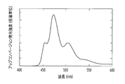
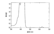
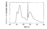
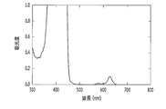
- FIG. 3 is a diagram showing an up-conversion emission spectrum of the light wavelength conversion element obtained in Example 1. It is a figure which shows the light absorption spectrum of the light wavelength conversion element obtained in Example 1.
- FIG. 2 It is a figure which shows the up-conversion emission spectrum of the light wavelength conversion element obtained in Example 2 and Comparative Example 2. It is a figure which shows the light absorption spectrum of the optical wavelength conversion element obtained in Example 2.
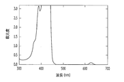
- FIG. It is a figure which shows the light absorption spectrum of the light wavelength conversion element obtained by the comparative example 2.
- FIG. 3 is a diagram showing an up-conversion emission spectrum of the light wavelength conversion element obtained in Example 1. It is a figure which shows the light absorption spectrum of the light wavelength conversion element obtained in Example 1.
- FIG. 2 It is a figure which shows the up-conversion emission spectrum of the light wavelength conversion element obtained in Example 2 and Comparative Example 2. It is a figure which shows the light absorption spectrum of the optical wavelength conversion element obtained in Example 2.
- FIG. It is a figure which shows the light absorption spectrum of
- FIG. 6 is a diagram showing an up-conversion emission spectrum of the light wavelength conversion element obtained in Example 3.
- FIG. 6 is a diagram showing an up-conversion emission spectrum of the light wavelength conversion element obtained in Example 3.
- FIG. It is a figure which shows the light absorption spectrum of the light wavelength conversion element obtained in Example 4.
- FIG. It is a figure which shows the up-conversion emission spectrum of the light wavelength conversion element obtained in Example 4.
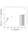
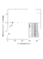
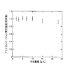
- FIG. 10 is a graph showing changes in up-conversion emission intensity (peak emission intensity) with respect to changes in gel concentration of the light wavelength conversion elements obtained in Examples 8 to 14.
- the light wavelength conversion element of the present invention is obtained by dissolving and / or dispersing an organic photosensitizing molecule (A) and an organic light emitting molecule (B), which are a combination showing a TTA process, in an ionic liquid (C).
- a homogeneous and transparent light wavelength conversion element wherein when the ionic liquid (C) has washed the ionic liquid (C) with 9 times its volume of ultrapure water, the pH of the water after washing is It will be greater than 5.
- the organic photosensitizing molecule (A) and the organic light emitting molecule (B) can be used without limitation as long as the combination exhibits a TTA process (light emission based on the TTA process).
- the absorption wavelength of the organic photosensitizer molecule (A) and the emission wavelength of the organic light emitting molecule (B) can be selected without limitation from within the wavelength range of sunlight.
- a ⁇ -conjugated molecule having a light absorption band in the visible to near infrared region is used as the organic photosensitizer molecule (A).
- a ⁇ -conjugated molecule having a light emission band in the visible to near infrared region can be used as the organic light emitting molecule (B).
- the organic photosensitizing molecule (A) and the organic light emitting molecule (B) include aromatic ⁇ -electron conjugated compounds, particularly polycyclic aromatic ⁇ -electron conjugated compounds, and for example, described in Non-Patent Document 5.
- a wide range of low molecules and polymers can be used.
- the organic photosensitizer molecule (A) can be used without limitation as long as it has an absorption maximum wavelength in the wavelength range of sunlight, but usually has an absorption maximum wavelength in the range of 200 to 1000 nm. And those having an absorption maximum wavelength in the range of 500 to 700 nm are preferably used.
- a relatively long wavelength light that is not used in a light-secondary energy conversion element such as a general solar cell or a hydrogen generation photocatalyst can be converted into a relatively short wavelength that is used in a general light-secondary energy conversion element. Therefore, light in a wide wavelength range included in sunlight can be effectively used in the light-secondary energy conversion element.
- any molecular species that has not been called a dye can be used as long as it has light absorption in a range from the ultraviolet region to the infrared region.
- the organic photosensitizer molecule (A) include acenaphthene derivatives, acetophenone derivatives, anthracene derivatives, diphenylacetylene derivatives, acridan derivatives, acridine derivatives, acridone derivatives, thioacridone derivatives, angelicin derivatives, anthracene derivatives, anthraquinone derivatives, azafluorenes.
- Derivatives azulene derivatives, benzyl derivatives, carbazole derivatives, coronene derivatives, sumanene derivatives, biphenylene derivatives, fluorene derivatives, perylene derivatives, phenanthrene derivatives, phenanthroline derivatives, phenazine derivatives, benzophenone derivatives, pyrene derivatives, benzoquinone derivatives, biacetyl derivatives, bianthranyl derivatives , Fullerene derivatives, graphene derivatives, carotene derivatives, chlorophyll derivatives, Derivatives, cinnoline derivatives, coumarin derivatives, curcumin derivatives, dansylamide derivatives, flavone derivatives, fluorenone derivatives, fluorescein derivatives, helicene derivatives, indene derivatives, lumichrome derivatives, lumiflavin derivatives, oxadiazole derivatives, oxazole derivatives, perifuranthene derivatives
- organic photosensitizing molecule (A) examples include metal porphyrins (metal complexes of porphyrins); metal tetraazaporphyrins; metal phthalocyanines; and iodine derivatives of 3,5-dimethyl-boron dipyrromethene.
- Boron dipyrromethenes such as iodine derivatives of 3,5-dimethyl-8-phenylboron dipyrromethene; Schiff base metal complexes such as salen metal complexes; metals such as rubidium-bipyridine complexes and iridium-phenanthroline complexes; Bipyridine complexes; metal phenanthroline complexes; naphthalenediimides such as N-alkylnaphthalenediimide; and acridones such as N-methylacridone, but are not limited thereto.
- a metal atom contained in the metal porphyrins and metal phthalocyanines Pt, Pd, Ru, Rh, Ir, Zn, Cu and the like can be used.
- metal tetraazaporphyrins examples include metal tetraazaporphyrins having a structure in which carbon atoms at positions 5, 10, 15, 20 and R 8 bonded thereto in the general formula (5) described later are replaced with nitrogen atoms. .
- a compound having an absorption maximum wavelength in the range of 500 to 700 nm includes the following general formula (5)
- each of R 7, represents any substituent including hydrogen atoms, R 7 may be the same or different, any substituent including hydrogen atoms linked to each other two R 7 adjacent to each other may form a 5- or 6-membered ring containing the group, each R 8 represents an aryl group having a substituent containing a hydrogen atom, R 8 may be the same or different, M is Represents a metal atom
- the “arbitrary substituent containing a hydrogen atom” means a hydrogen atom or an arbitrary substituent other than a hydrogen atom.
- R 7 in the general formula (5) examples include hydrogen atom, alkyl group (eg, alkyl group having 1 to 12 carbon atoms), alkenyl group, alkynyl group, halogen atom, hydroxy group (hydroxyl group), alkylcarbonyloxy Group, arylcarbonyloxy group, alkoxycarbonyloxy group, aryloxycarbonyloxy group, carboxylate, alkylcarbonyl group, arylcarbonyl group, alkoxycarbonyl group, aminocarbonyl group, alkylaminocarbonyl group, dialkylaminocarbonyl group, alkylthiocarbonyl Group, alkoxyl group, phosphate group, phosphonate group, phosphinate group, cyano group, amino group (including alkylamino group, dialkylamino group, arylamino group, diarylamino group, and alkylarylamino group), Acylamino groups (including alkylcarbonylamino groups, aryl
- Examples of the substituent that the 5-membered ring or the 6-membered ring formed by linking two R 7 adjacent to each other, which can be included in the general formula (5), are listed as examples of R 7 Although a substituent is mentioned, it is not limited to these.
- the 5-membered ring or 6-membered ring may be linked to another porphyrin ring which may have a substituent.
- Examples of R 8 in the general formula (5) include, but are not limited to, the substituents mentioned as examples of R 7 .
- Examples of the metal atom contained in the metal porphyrins and metal phthalocyanines include Pt, Pd, Ru, Rh, Ir, Zn, Cu and the like as the metal atom M in the general formula (5).
- Examples of the metal porphyrins represented by the general formula (5) include meso-tetraphenyl-tetrabenzoporphyrin metal complexes such as meso-tetraphenyl-tetrabenzoporphyrin palladium (CAS number: 119654-64-7), Octaethylporphyrin metal complexes such as octaethylporphyrin palladium (CAS number: 24804-00-0), and meso-tetraphenyl-octamethoxy-tetranaphtho [2,3] porphyrin palladium described in Non-Patent Document 5 An ethyl porphyrin metal complex etc. are mentioned.
- meso-tetraphenyl-tetrabenzoporphyrin metal complexes such as meso-tetraphenyl-tetrabenzoporphyrin palladium and octaethylporphyrin metal complexes such as octaethylporphyrin palladium are preferable.
- the organic photosensitizer molecule (A) is more preferably an organic photosensitizer molecule having a structure containing no metal in the structure. Thereby, it is possible to avoid the occurrence of environmental pollution due to metal at the time of manufacturing or discarding the optical wavelength conversion element.
- organic photosensitizing molecules having a structure that does not contain metal in the structure include the following general formula (1)
- R 1 to R 5 each independently represent an arbitrary substituent containing a hydrogen atom, and adjacent substituents (a pair of R 1 and R 2 , a pair of R 2 and R 4 , R pair 1 and R 3, a pair of R 3 and R 4) may form a 5- or 6-membered ring having an optional substituent containing a hydrogen atom each linked to each other, R 6 is A halogen atom, an optionally substituted alkyl group having 1 to 5 carbon atoms, or an optionally substituted alkoxyl group having 1 to 5 carbon atoms) Compound represented by (boron dipyrromethene compound), C 70, and the like.
- R 1 to R 5 in the general formula (1) examples include hydrogen atom, alkyl group, alkenyl group, alkynyl group, halogen atom, hydroxy group (hydroxyl group), alkylcarbonyloxy group, arylcarbonyloxy group, alkoxy Carbonyloxy group, aryloxycarbonyloxy group, carboxylate, alkylcarbonyl group, arylcarbonyl group, alkoxycarbonyl group, aminocarbonyl group, alkylaminocarbonyl group, dialkylaminocarbonyl group, alkylthiocarbonyl group, alkoxyl group, phosphate group Phosphonate group, phosphinate group, cyano group, amino group (including alkylamino group, dialkylamino group, arylamino group, diarylamino group, and alkylarylamino group), acylamino group (alkyl Nilamino group, arylcarbonylamino group, carbamoyl group, and ure
- Substituents adjacent to each other include, but are not limited to, the substituents listed as examples of R 1 to R 5 .
- R 1 and R 4 in the general formula (1) are a hydrogen atom, a halogen atom, an optionally substituted aliphatic hydrocarbon group having 1 to 4 carbon atoms, or an optionally substituted phenyl.
- a phenoxy group which may have a substituent a thienyl group which may have a substituent, a thienoxy group which may have a substituent, the following formula (2)
- 2-carboxyl-2-cyanoethenyl group more preferably an alkyl group having 1 to 3 carbon atoms which may have a substituent, and unsubstituted 1 to 3 carbon atoms. More preferred is an alkyl group, and most preferred is an unsubstituted methyl group.
- R 2 and R 3 in the general formula (1) are a hydrogen atom, a halogen atom, an optionally substituted aliphatic hydrocarbon group having 1 to 4 carbon atoms, or an optionally substituted phenyl.
- R 5 in the general formula (1) is a hydrogen atom, a halogen atom, an optionally substituted aliphatic hydrocarbon group having 1 to 4 carbon atoms, an optionally substituted phenyl group, or a substituted group.
- R 6 in the general formula (1) is a halogen atom, an alkyl group having 1 to 5 carbon atoms which may have a substituent, or an alkoxyl group having 1 to 5 carbon atoms which may have a substituent. However, it is preferably a fluorine atom.
- the organic photosensitizing molecule (A) is preferably a metalloporphyrin represented by the general formula (5) or a compound represented by the general formula (1).
- the compound represented by the general formula (1) is more preferably a compound represented by the general formula (1), wherein R 1 to R 5 in the general formula (1) each independently represents a hydrogen atom, a halogen atom, or a substituent.
- An optionally substituted aliphatic hydrocarbon group having 1 to 4 carbon atoms a phenyl group which may have a substituent, a phenoxy group which may have a substituent, a thienyl group which may have a substituent, It is a compound which may be a thienoxy group which may have a substituent, a 2-carboxyl ethenyl group represented by the formula (2), or a 2-carboxyl-2-cyanoethenyl group represented by the formula (3). More preferably, the following general formula (4)
- R 1 and R 4 each independently represents an alkyl group having 1 to 3 carbon atoms which may have a substituent
- R 2 and R 3 each independently represent a hydrogen atom, a bromine atom, or iodine.
- at least one of R 2 and R 3 is a bromine atom or an iodine atom
- R 5 represents a phenyl group which may have a substituent.
- it is a compound represented by these.
- organic photosensitizer molecules (A) may be used alone or in combination of two or more.
- the organic light-emitting molecule (B) is not particularly limited as long as it is an organic compound that can be used together with the organic photosensitizer molecule (A) to emit light up-converted by the TTA process. Can be used.
- Examples of the organic light emitting molecule (B) include acenaphthene derivatives, acetophenone derivatives, anthracene derivatives, diphenylacetylene derivatives, acridan derivatives, acridine derivatives, acridone derivatives, thioacridone derivatives, angelicin derivatives, anthracene derivatives, anthraquinone derivatives, azafluorene derivatives, Azulene derivatives, benzyl derivatives, carbazole derivatives, coronene derivatives, sumanene derivatives, biphenylene derivatives, fluorene derivatives, perylene derivatives, phenanthrene derivatives, phenanthroline derivatives, phenazine derivatives
- organic light-emitting molecule (B) examples include 9,10-diphenylanthracene (CAS number: 1499-10-1) and derivatives thereof, and 9,10-bis (phenylethynyl) anthracene (CAS number).
- the organic light emitting molecule (B) is preferably a condensed polycyclic aromatic compound such as perylene, pyrene or anthracene or a derivative thereof. These organic light emitting molecules (B) may be used alone or in combination of two or more.
- the contents of the organic photosensitizer molecule (A) and the organic light emitting molecule (B) in the light wavelength conversion element of the present invention are not particularly limited, but each is usually normal when the light wavelength conversion element is 100 parts by mass. Is 0.000001 to 10 parts by mass, preferably 0.00001 to 5 parts by mass, and more preferably 0.0001 to 1 part by mass.
- the ionic liquid (C) is a room temperature molten salt (a salt in a molten state (liquid state) at room temperature (25 ° C.)) composed of a cation and an anion. Generally, it is known that there are at least 1,000,000 kinds of compounds as ionic liquids depending on the combination of a cation and an anion.
- the ionic liquid (C) acts as a medium for the organic photosensitizing molecule (A) and the organic light emitting molecule (B), which is a combination showing the TTA process, and inside the organic photosensitizing molecule (A) and the organic The diffusion movement of the luminescent molecule (B) is allowed.
- the organic photosensitizing molecule (A) and the organic light emitting molecule (B), which are a combination showing the TTA process, are dissolved and / or dispersed in the ionic liquid (C) and visually observed. Since it is necessary to make it homogeneous and transparent, the ionic liquid (C) has a cation- ⁇ interaction with the organic photosensitizer molecule (A) and the organic light emitting molecule (B) and is immiscible with water.
- the ionic liquid (C) is “non-water miscible” means that 50% by mass or less of water is visually and homogeneously mixed with the ionic liquid (C) at 25 ° C. (for example, 5% by mass or less of water may be visually homogeneously and transparently mixed with the ionic liquid (C)), but 50% by mass of water is not visually homogeneously and transparently mixed with the ionic liquid (C). means.
- the cation constituting the ionic liquid (C) include, for example, a nitrogen-containing compound cation, a quaternary phosphonium cation, a sulfonium cation, and the like.
- the nitrogen-containing compound cation include heterocyclic aromatic amine cations such as imidazolium cation and pyridinium cation; piperidinium cation, pyrrolidinium cation, pyrazolium cation, thiazolium cation, and morpholinium cation.
- Heterocyclic aliphatic amine cations such as quaternary ammonium cations, aromatic amine cations, aliphatic amine cations, and alicyclic amine cations.
- Examples of the imidazolium cation include 1-ethyl-3-methylimidazolium, 1-butyl-3-methylimidazolium, 1-hexyl-3-methylimidazolium, and 1-octyl-3-methylimidazolium.
- 1-alkyl-3-methylimidazolium 1-ethyl-2,3-dimethylimidazolium, 1-propyl-2,3-dimethylimidazolium, 1-butyl-2,3-dimethylimidazolium, 1-pentyl- 1-alkyl-2 such as 2,3-dimethylimidazolium, 1-hexyl-2,3-dimethylimidazolium, 1-heptyl-2,3-dimethylimidazolium, 1-octyl-2,3-dimethylimidazolium , 3-Dimethylimidazolium; 1-cyanomethyl-3-methylimidazolium, 1- (2-hydride Kishiechiru) -3-methylimidazolium, and the like.
- Examples of the pyridinium cation include 1-butylpyridinium, 1-hexylpyridinium, N- (3-hydroxypropyl) pyridinium, N-hexyl-4-dimethylaminopyridinium, and the like.
- Examples of the piperidinium cation include 1- (methoxyethyl) -1-methylpiperidinium.
- Examples of the pyrrolidinium cation include 1- (2-methoxyethyl) -1-methylpyrrolidinium, N- (methoxyethyl) -1-methylpyrrolidinium, and the like.
- Examples of the morpholinium cation include N- (methoxyethyl) -N-methylmorpholium.
- Examples of the quaternary ammonium cation include N, N-diethyl-N-methyl-N- (2-methoxyethyl) ammonium, N-ethyl-N, N-dimethyl-2-methoxyethylammonium and the like.
- Examples of the quaternary phosphonium cation include tetraalkylphosphonium and tetraphenylphosphonium.
- Examples of the sulfonium cation include trialkylsulfonium and triphenylsulfonium. One kind of these cations may be present in the ionic liquid (C), or two or more kinds may be present.
- the cation constituting the ionic liquid (C) may be an organic photosensitizing molecule. Those having a “cation- ⁇ interaction” between (A) and the organic light emitting molecule (B) are preferred.
- the anion constituting the ionic liquid (C) is not particularly limited.
- an ionic liquid is miscible with water depending on the type of anion that constitutes the ionic liquid, but depending on the type of anion that constitutes the ionic liquid, the ionic liquid is not miscible with water to a certain extent, or a very small amount. Only miscible.
- the anion of the ionic liquid (C) is converted into the ionic liquid.
- An anion that imparts non-water miscibility is preferred.
- ionic liquid (C) a combination of a specific example of the anion and a specific example of the cation can be used.
- the ionic liquid (C) more specifically, for example, 1-ethyl-3-methylimidazolium bis (trifluoromethylsulfonyl) imide (CAS number: 174899-82-2, for example, the manufacturer is Ionic Liquids Technologies) GmbH is commercially available), 1-propyl-2,3-dimethylimidazolium bis (trifluoromethylsulfonyl) imide (CAS number: 169051-76-7, for example, manufacturer is Ionic Liquids Technologies GmbH Is commercially available from Merck KGaA), 1-butyl-3-methylimidazolium bis (trifluoromethylsulfonyl) imide (CAS number: 174899-83-3, for example, manufactured by Ionic Liq commercial products of ids Technologies GmbH or commercially available from Merck KGaA), 1-propyl-2,3-d
- Kanto Chemical Co., Ltd. 1-hexyl-3-methylimidazolium bis (trifluoromethylsulfonyl) imide (CAS) Number: 38215 -50-7, for example, the manufacturer can obtain a commercial product of Merck KGaA, 1-octyl-3-methylimidazolium bis (trifluoromethylsulfonyl) imide (CAS number: 178631-04-4, for example, the manufacturer is Nisshinbo Commercially available from Kanto Chemical Co., Inc.
- the organic light is selected from the ionic liquid (C).
- a combination of a cation having a “cation- ⁇ interaction” between the sensitizing molecule (A) and the organic light-emitting molecule (B) and an anion that imparts non-water miscibility to the ionic liquid is preferable.
- the ionic liquid (C) Also, non-water miscible ones are preferable.
- Examples of the ionic liquid (C) include 1-ethyl-3-methylimidazolium bis (trifluoromethylsulfonyl) imide, 1-propyl-2,3-dimethylimidazolium bis ( Trifluoromethylsulfonyl) imide, 1-butyl-3-methylimidazolium bis (trifluoromethylsulfonyl) imide, 1-propyl-2,3-dimethylimidazolium tris (trifluoromethylsulfonyl) methide, N, N-diethyl -N-methyl-N- (2-methoxyethyl) ammonium bis (trifluoromethylsulfonyl) imide, 1-hexyl-3-methylimidazolium bis (trifluoromethylsulfonyl) imide, 1-octyl-3-methylimidazolium Bis (trifluoromethylsulfonyl) 1-ethyl-2,3-dimethyl
- the viscosity of the ionic liquid (C) at 26 ° C. is usually 10 mPa ⁇ s or more, preferably 50 mPa ⁇ s or more, more preferably 70 mPa ⁇ s or more.
- the ionic liquid (C) contained in the light wavelength conversion element of the present invention is such that the pH of water after washing becomes higher than 5 when the ionic liquid is washed with 9 times its volume of ultrapure water. Thereby, an optical wavelength conversion element having higher optical wavelength conversion efficiency and better temporal stability can be realized.
- the pH of the water after washing is 9 times that of the ionic liquid (C) (by volume ratio). (9 times the volume) ultrapure water is added and stirred, and then the aqueous layer is separated and the pH of the aqueous layer is measured.
- ionic liquids often exhibit an acidic pH of 5 or less after washing when the ionic liquid is washed with 9 times its volume of ultrapure water.
- the pH of the water after washing is greater than 5 when washed with 9 times the volume of ultrapure water. It is necessary to obtain such an ionic liquid (C) and use the ionic liquid (C).
- Examples of the method for removing impurities from the ionic liquid include (1) a method of treating the ionic liquid with activated carbon, (2) a method of washing the ionic liquid with water, and (3) a method of washing the ionic liquid with an organic solvent (for example, see JP 2012-144441 A), (4) After obtaining a solution by dissolving an ionic liquid in a solvent, the temperature of the solution is lowered to crystallize the ionic liquid from the solution, and the crystallized ionic liquid (5) A column packed with a filler such as alumina after obtaining a solution by dissolving an ionic liquid in a solvent.
- (6) a method of treating an ionic liquid with a metal hydride (Japanese Patent Laid-Open No. 2005-89313) Reference), and the like. A plurality of these methods may be used in combination.
- water preferably ultrapure water
- the washing treatment for removing the aqueous layer is repeated until the pH of the water after washing becomes higher than 5.
- a method of distilling water (drying) by heating under reduced pressure can be used.
- the light wavelength conversion element of the present invention is a solution or dispersion obtained by dissolving and / or dispersing an organic photosensitizer molecule (A) and an organic light emitting molecule (B) in an ionic liquid (C) using a generally known technique.
- Can be produced by a method of obtaining In the above method, if necessary, other additives are mixed with the organic photosensitizer molecule (A) and the organic light emitting molecule (B) in the ionic liquid (C) using a generally known technique, and the solution or A dispersion may be obtained.
- a known disperser such as an ultrasonic disperser, a bead mill, a homogenizer, a wet jet mill, a ball mill, an attritor, a sand mill, a roll mill, and a microwave disperser may be used alone or in combination.
- the organic photosensitizing molecule (A) and the organic light emitting molecule (B) may be finely pulverized and finely dispersed to obtain a solution or dispersion.
- the organic photosensitizer molecule (A) and the organic light emitting molecule (B) are dissolved and / or dispersed in a volatile organic solvent, Next, the obtained solution and / or dispersion is stirred and mixed with the ionic liquid (C) to form a visually homogeneous and transparent solution and / or dispersion, and the solution and / or dispersion is further subjected to reduced pressure.
- the method of removing this volatile organic solvent to a trace amount or less can also be used. This method makes it easy to obtain a light wavelength conversion element that is homogeneously and transparently mixed, and a light wavelength conversion element having high stability and high light wavelength conversion efficiency can be obtained. Therefore, the light wavelength conversion element of the present invention is obtained. More preferable as a method.
- the volatile organic solvent used in the method can dissolve and / or disperse the organic photosensitizer molecule (A) and the organic light emitting molecule (B), and can be mixed homogeneously and transparently with the ionic liquid (C). Furthermore, there is no particular limitation as long as it is a volatile organic solvent that can be removed to a trace amount under reduced pressure.
- the “trace amount” is an amount that can detect the volatile organic solvent mixed in the ionic liquid (C) only at a noise level or less based on the measurement of the light absorption spectrum.
- the volatile organic solvent is preferably a volatile organic solvent that can dissolve the organic photosensitizing molecule (A) and the organic light emitting molecule (B).
- the volatile organic solvent aromatic solvents such as toluene, benzene and xylene can be used.
- a volatile organic solvent capable of dissolving the organic photosensitizing molecule (A) and the organic light emitting molecule (B) is used, the volatile organic solvent matches the solubility of the organic photosensitizing molecule and the organic light emitting molecule. Can be selected as appropriate.
- stirring and mixing means known techniques or devices such as ultrasonic waves, bubbling, agitators, liquid feed pumps, pulverizers, bead mills, homogenizers, wet jet mills, and microwaves can be used. These means may be used alone or in combination of two or more.
- the light wavelength conversion element of the present invention may further contain a gelling agent (D). Since the light wavelength conversion element having the above-described structure contains the gelling agent (D), the fluidity is suppressed as compared with the case where the gelling agent (D) is not included, and the solar cell, photocatalyst, photocatalytic hydrogen, When used in an article such as an oxygen generator or an optical up-conversion filter, the light wavelength conversion element hardly leaks.
- a gelling agent (D) Since the light wavelength conversion element having the above-described structure contains the gelling agent (D), the fluidity is suppressed as compared with the case where the gelling agent (D) is not included, and the solar cell, photocatalyst, photocatalytic hydrogen, When used in an article such as an oxygen generator or an optical up-conversion filter, the light wavelength conversion element hardly leaks.
- the light wavelength conversion element of the present invention further comprising a gelling agent (D) is preferably in a gel state.
- a gelling agent (D) is preferably in a gel state.
- the gelling agent (D) a gel that is dissolved in the ionic liquid (C) and has a light transmittance that does not inhibit the light absorption of the organic photosensitizing molecule (A) and the light emission of the organic light emitting molecule (B).
- an ionic gelling agent and a nonionic polymer are preferable because a gel having sufficient light permeability can be formed.
- An ionic gelling agent is more preferable because a gel can be easily formed in D).
- A represents a divalent group or cyclohexanediyl group having one or more aromatic rings which may have a substituent
- B represents an alkylene having 1 to 10 carbon atoms which may have a substituent.
- X - represents a monovalent anion
- n is in each molecule represents a positive integer
- the average value of n of the total molecule is from 1 to 800
- the cyclohexanediyl group is, for example, a cyclohexane-1,4-diyl group.
- B in the general formula (A) is preferably an alkylene group having 1 to 6 carbon atoms which may have a substituent, and an alkylene having 2 to 6 carbon atoms which may have a substituent. More preferably, it is a group.
- the substituent that the alkylene group may have include an alkyl group having 1 to 6 carbon atoms such as methyl, ethyl, and propyl groups; an alkoxy group having 1 to 6 carbon atoms such as methoxy, ethoxy, and propoxy groups. It is done.
- B in the general formula (A) include, for example, methylene group, ethane-1,2-diyl group, propane-1,4-diyl group, butane-1,4-diyl group, hexane-1 , 6-diyl group, 2-butene-1,4-diyl group and the like.
- X ⁇ in the general formula (A) is not limited, and examples thereof include halide ions (F ⁇ , Cl ⁇ , Br ⁇ , or I ⁇ ), bis (trifluoromethanesulfonyl) amide ions, Bis (fluorosulfonyl) amide ion, tetrafluoroborate ion (BF 4 ⁇ ), hexafluorophosphate ion (PF 6 ⁇ ), thiocyanate ion (SCN ⁇ ), nitrate ion (NO 3 ⁇ ), methosulphate ion ( CH 3 OSO 3 ⁇ ), bicarbonate ion (HCO 3 ⁇ ), hypophosphite ion (H 2 PO 2 ⁇ ), halogen oxoacid ion (YO 4 ⁇ , YO 3 ⁇ , YO 2 ⁇ , or YO ⁇ Y represents Cl, Br, or I), tris (tri
- X ⁇ in the general formula (A) is preferably bis (trifluoromethanesulfonyl) amide ion, bis (fluorosulfonyl) amide ion, or tetrafluoroborate ion (BF 4 ⁇ ).
- Preferred examples of the compound represented by the general formula (A) include the following general formula
- B represents an ethylene group, a 1,3-propylene group, a 1,4-butylene group or a 1,6-hexalene group
- X ⁇ represents a halide ion (F ⁇ , Cl ⁇ , Br ⁇ , or I ⁇ ), bis (trifluoromethanesulfonyl) amide ion, bis (fluorosulfonyl) amide ion, tetrafluoroborate ion (BF 4 ⁇ ), hexafluorophosphate ion (PF 6 ⁇ ), thiocyanate ion (SCN ⁇ ), nitrate ion (NO 3 ⁇ ), methosulfate ion (CH 3 OSO 3 ⁇ ), bicarbonate ion (HCO 3 ⁇ ), hypophosphite ion (H 2 PO 2 ⁇ ), halogen oxoacid Ion (YO 4 ⁇ ,
- the concentration of the ionic gelling agent in the light wavelength conversion element of the present invention is usually 0.3 to 100 g / L, preferably 0.5 to 60 g, although it depends on the value of n of the ionic gelling agent. More preferably, it is 1 to 20 g.
- concentration of the ionic gelling agent is less than 0.3 g / L, the light wavelength conversion element may not be sufficiently gelled.
- concentration of the ionic gelling agent exceeds 100 g / L, the light transmittance of the gel formed by dissolving the ionic gelling agent in the ionic liquid (C) is lowered, and the light wavelength conversion of the light wavelength conversion element There is a risk that the characteristics will deteriorate.
- the nonionic polymer at least one kind of a compound capable of forming a nonionic polymer by a polymerization reaction described in detail later can be used.
- the nonionic polymer preferably has a lower absorbance.
- the light wavelength conversion element of the present invention containing the gelling agent (D) is, for example, (1) organic photosensitizing molecule (A) and organic A solution and / or dispersion obtained by dissolving and / or dispersing the luminescent molecule (B) in the ionic liquid (C) is mixed with a mixture (solution or gel) of the ionic gelling agent and the ionic liquid (C). Method, (2) A solution and / or dispersion obtained by dissolving and / or dispersing the organic photosensitizing molecule (A) and the organic light emitting molecule (B) in the ionic liquid (C) is used as an ionic gelling agent.
- the method (1) After mixing with a solution dissolved in an organic solvent, it can be produced by using a method such as a method of distilling off the organic solvent.
- the method (1) can avoid the organic solvent remaining in the light wavelength conversion element, and the light wavelength conversion element in a more solid gel state. Is more preferable.
- a solution and / or dispersion obtained by dissolving and / or dispersing the organic photosensitizing molecule (A) and the organic light emitting molecule (B) in the ionic liquid (C) is, for example, an organic photosensitizing molecule (A ) Is dissolved in a volatile organic solvent to prepare a solution of the organic photosensitizing molecule (A), and the organic light emitting molecule (B) is dissolved in a volatile organic solvent to prepare the organic photosensitizing molecule (B).
- a solution can be prepared, and the organic photosensitizing molecule (A) solution, the organic photosensitizing molecule (B) solution, and the ionic liquid (C) can be mixed and then homogenized by stirring. .
- the mixture of the ionic gelling agent and the ionic liquid (C) is, for example, dissolved and / or dispersed in a volatile organic solvent, then mixed with the ionic liquid (C), heated and reduced in pressure. It can manufacture using the method of distilling a volatile organic solvent under, the method of mixing and heating an ionic gelling agent and an ionic liquid (C), etc.
- the former method can be mixed into an ionic liquid (C) by heating at a relatively low temperature (for example, 90 ° C. or lower) to form a solution or gel.
- a relatively low temperature for example, 90 ° C. or lower
- the volatile organic solvent using the ionic gelling agent in the preparation of the mixture of the ionic liquid (C) can dissolve and / or disperse the ionic gelling agent and is homogeneous with the ionic liquid (C).
- the “trace amount” is an amount that can detect the volatile organic solvent mixed in the ionic liquid (C) only at a noise level or less based on the measurement of the light absorption spectrum.
- the volatile organic solvent is preferably a volatile organic solvent that can dissolve the ionic gelling agent.
- an alcohol solvent such as methanol can be used.
- the light wavelength conversion element of the present invention containing the gelling agent (D) is, for example, (I) organic photosensitizing molecule (A) and organic After impregnating a nonionic polymer with a mixed solution and / or dispersion of a volatile organic solvent and an ionic liquid (C) in which the luminescent molecule (B) is dissolved and / or dispersed, A method of removing a volatile organic solvent, and (II) a solution and / or dispersion obtained by dissolving and / or dispersing the organic photosensitizer molecule (A) and the organic light emitting molecule (B) in the ionic liquid (C).
- (I) organic photosensitizing molecule (A) and organic After impregnating a nonionic polymer with a mixed solution and / or dispersion of a volatile organic solvent and an ionic liquid (C) in which the luminescent molecule (B) is dissolved and / or dispersed A method of removing
- polymerizable compound a compound capable of forming a nonionic polymer by a polymerization reaction
- polymerizable compound a compound capable of forming a nonionic polymer by a polymerization reaction
- a solution and / or dispersion obtained by dissolving and / or dispersing the organic photosensitizing molecule (A) and the organic light emitting molecule (B) in a volatile organic solvent and an ionic liquid (C) is, for example, organic light.
- the organic sensitizing molecule (A) is dissolved in a volatile organic solvent to prepare a solution of the organic photosensitizing molecule (A), and the organic light emitting molecule (B) is dissolved in a volatile organic solvent to prepare an organic photosensitizing solution.
- a solution of the molecule (B) is prepared, and the solution of the organic photosensitized molecule (A), the solution of the organic photosensitized molecule (B), and the ionic liquid (C) are mixed and homogenized by stirring. Can be manufactured.
- the order of mixing the organic photosensitizing molecule (A) solution, the organic photosensitizing molecule (B) solution, and the ionic liquid (C) is not particularly limited.
- the ionic liquid ( For C) after the organic photosensitizing molecule (B) solution is mixed, the organic photosensitizing molecule (A) solution and the organic photosensitizing molecule (B) solution may be mixed.
- the organic photosensitizing molecule (A) and the organic light emitting molecule (B) are each only one of the volatile organic solvent and the ionic liquid (C). And may be dissolved and / or dispersed in both the volatile organic solvent and the ionic liquid (C) in any ratio.
- the dispersion can be produced by a method in which the organic photosensitizer molecule (A) and the organic light emitting molecule (B) are dissolved and / or dispersed in the ionic liquid (C) using a generally known technique.
- other additives are mixed with the organic photosensitizer molecule (A) and the organic light emitting molecule (B) in the ionic liquid (C) using a generally known technique, and the solution is added.
- a disperser such as an ultrasonic disperser, a bead mill, a homogenizer, a wet jet mill, a ball mill, an attritor, a sand mill, a roll mill, and a microwave disperser may be used alone or in combination.
- the organic photosensitizing molecule (A) and the organic light emitting molecule (B) may be finely pulverized and finely dispersed to obtain the solution and / or dispersion.
- a second method for producing the dispersion for example, first, the organic photosensitizer molecule (A) and the organic light emitting molecule (B) are dissolved and / or dispersed in a volatile organic solvent, and then obtained. The resulting solution and / or dispersion is agitated and mixed with the ionic liquid (C) to produce a visually homogeneous and transparent solution and / or dispersion, which is further volatile under reduced pressure from the solution and / or dispersion.
- a method of removing the organic solvent to a trace amount or less can also be used.
- a light wavelength conversion element in a state of being homogeneously and transparently mixed can be easily obtained, and a light wavelength conversion element having high stability and high light wavelength conversion efficiency can be obtained. Therefore, the organic photosensitizing molecule (A) and This is more preferable as a method for obtaining a solution or dispersion obtained by dissolving and / or dispersing the organic light emitting molecule (B) in the ionic liquid (C).
- the volatile organic solvent used in the method (I) and the second method can dissolve and / or disperse the organic photosensitizing molecule (A) and the organic light emitting molecule (B), and is an ionic liquid.
- a volatile organic solvent that can be mixed homogeneously and transparently with (C) and can be removed to a trace amount under reduced pressure.
- the “trace amount” is an amount that can detect the volatile organic solvent mixed in the ionic liquid (C) only at a noise level or less based on the measurement of the light absorption spectrum.
- the volatile organic solvent is preferably a volatile organic solvent that can dissolve the organic photosensitizing molecule (A) and the organic light emitting molecule (B).
- the volatile organic solvent aromatic solvents such as toluene, benzene and xylene can be used.
- a volatile organic solvent capable of dissolving the organic photosensitizing molecule (A) and the organic light emitting molecule (B) is used, the volatile organic solvent matches the solubility of the organic photosensitizing molecule and the organic light emitting molecule. Can be selected as appropriate.
- stirring and mixing means in the method (I) and the second method known techniques such as ultrasonic waves, bubbling, agitator, liquid feed pump, pulverizer, bead mill, homogenizer, wet jet mill, microwave, etc.
- An apparatus can be used. These means may be used alone or in combination of two or more.
- the amount of gelling agent (D) used is usually less than that when an ionic gelling agent is used in order to achieve sufficient gelation.
- the content of the ionic liquid (C) when the entire light wavelength conversion element is 100 parts by mass is usually 10 parts by mass or more, and preferably 30 parts by mass or more.
- the nonionic polymer used in the method (I) is not particularly limited, but the organic photosensitizing molecule (A) and the organic light emitting molecule (B) are dissolved in the ionic liquid (C).
- a nonionic acrylic resin is preferable because it can easily swell after absorbing and / or dispersing the solution or dispersion.
- the nonionic acrylic resin is composed of a nonionic monomer composed mainly of (meth) acrylates ((meth) acrylic acid esters) such as methyl methacrylate, methyl acrylate, butyl acrylate, and hydroxyethyl methacrylate. It is a coalescence.
- (meth) acrylate means acrylate and / or methacrylate
- (meth) acryl means acryl and / or methacryl
- the nonionic polymer used in the method (I) may have any shape, for example, a film shape.
- the polymerizable compound used in the method (II) may be a compound capable of forming a nonionic polymer by a thermal polymerization reaction, or a compound capable of forming a nonionic polymer by a photopolymerization reaction. Also good.
- Examples of the compound capable of forming a nonionic polymer by the thermal polymerization reaction include nonionic (meth) acrylic esters such as methyl methacrylate, methyl acrylate, butyl acrylate, and hydroxyethyl methacrylate; acrylonitrile, methacrylate Nonionic (meth) acrylonitriles such as nitrile; Nonionic styrenes such as styrene, ⁇ -methylstyrene, p-methoxystyrene, p-cyanostyrene; Nonionic vinyl carboxylates such as vinyl acetate Nonionic chlorine-containing monomers such as vinyl chloride and vinylidene chloride; Nonionic (meth) acrylamides such as acrylamide; Nonionic fluorine-containing monomers such as tetrafluoroethylene; Methylvinyl Nonionic vinyl ketones such as ketones; Monomers such as olefins Ren and the like. These may
- a radical thermal polymerization initiator such as an azo compound or an organic peroxide is added to the compound capable of forming a nonionic polymer by the thermal polymerization reaction. And the thermal polymerization reaction of the compound may be performed.
- examples of the compound capable of forming a nonionic polymer by the thermal polymerization reaction include epoxy resins.
- the epoxy resins include an epoxy resin having an aliphatic cyclic structure, a bisphenol A type epoxy resin, and an aromatic polyfunctional epoxy resin having three or more epoxy groups in the molecule.
- the epoxy resins may be thermally cured using a basic curing agent such as an acid anhydride, an acid anhydride derivative, or an imidazole. In this method, a nonionic polymer with little coloration after curing can be obtained.
- Examples of the compound capable of forming a nonionic polymer by the photopolymerization reaction include monomers having a polymerizable group such as a vinyl group, a vinyl ether group, an allyl group, a maleimide group, and a (meth) acryloyl group. Among them, a monomer having a (meth) acryloyl group is preferable from the viewpoint of reactivity. Examples of the monomer having the (meth) acryloyl group include a monofunctional (meth) acrylate monomer having one (meth) acryloyl group in the structure; and a bifunctional having two (meth) acryloyl groups.
- (Meth) acrylate monomers such as a trifunctional or higher polyfunctional (meth) acrylate monomer having three or more acryloyl groups.
- (meth) acryloyl means acryloyl and / or methacryloyl.
- Examples of the monofunctional (meth) acrylate monomer include phenoxyethyl (meth) acrylate, phenyl (poly) ethoxy (meth) acrylate, p-cumylphenoxyethyl (meth) acrylate, tribromophenyloxyethyl (meth) ) Acrylate, phenylthioethyl (meth) acrylate, 2-hydroxy-3-phenyloxypropyl (meth) acrylate, phenylphenol (poly) ethoxy (meth) acrylate, phenylphenol epoxy (meth) acrylate, acryloylmorpholine, 2-hydroxy Propyl (meth) acrylate, 4-hydroxybutyl (meth) acrylate, cyclohexane-1,4-dimethanol mono (meth) acrylate, tetrahydrofurfuryl (meth) acrylate, Bornyl (meth) acrylate, dicyclopen
- bifunctional (meth) acrylate monomer examples include 1,4-butanediol di (meth) acrylate, 1,6-hexanediol di (meth) acrylate, 1,9-nonanediol di (meth) acrylate, Cyclodecane dimethanol di (meth) acrylate, bisphenol A polyethoxydi (meth) acrylate, bisphenol A polypropoxydi (meth) acrylate, bisphenol F polyethoxydi (meth) acrylate, ethylene glycol di (meth) acrylate, polyethylene glycol di (meth) Acrylate, di (meth) acrylate of ⁇ -caprolactone adduct of neopentyl glycol hydroxybivalate (for example, KAYARAD (registered trademark) HX-220, KAYARAD (manufactured by Nippon Kayaku Co., Ltd.)) Trademark) HX-620, etc.) and
- trifunctional or higher polyfunctional (meth) acrylate monomer examples include tris (acryloxyethyl) isocyanurate, pentaerythritol tetra (meth) acrylate, dipentaerythritol hexa (meth) acrylate, dipentaerythritol penta (meth).
- (meth) acrylate oligomers such as urethane (meth) acrylate, epoxy (meth) acrylate, and polyester (meth) acrylate can be used as the monomer having the (meth) acryloyl group. These may be used alone or in combination of two or more.
- a compound capable of forming a nonionic polymer by the photopolymerization reaction is added to a benzoin compound.
- one or more photopolymerization initiators such as acetophenones, anthraquinones, thioxanthones, ketals, benzophenones, and phosphine oxides are added, and the photopolymerization reaction of the compound is performed by irradiating with ultraviolet rays. Just do it.
- the light wavelength conversion element of the present invention preferably has a moisture content of 1% by mass or less, more preferably 0.1% by mass or less, and further preferably 0.01% by mass or less. Most preferably, it is 0.001 mass% or less. Thereby, the optical wavelength conversion element which has higher optical wavelength conversion efficiency is realizable.
- the light wavelength conversion element of the present invention preferably has an oxygen concentration of 100 ppm by mass or less, more preferably 10 ppm by mass or less, still more preferably 1 ppm by mass or less. Most preferably, it is 1 mass ppm or less. Thereby, the optical wavelength conversion element which has higher optical wavelength conversion efficiency is realizable.
- the light wavelength conversion element of the present invention is a visually homogeneous and transparent solution and / or dispersion, and also has good stability.
- the light wavelength conversion element of the present invention can be used for solar cells, photocatalysts, photocatalytic hydrogen / oxygen generators, optical up-conversion filters, and the like.
- the solar cell of the present invention uses the light wavelength conversion element of the present invention.
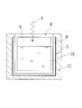
- a solar cell according to an example of the present invention includes a photoelectric conversion layer (solar cell layer) 1 and a strip-shaped light receiving surface electrode disposed on a light incident side surface of the photoelectric conversion layer 1. 7, a transparent back electrode 2 laminated on the back surface of the light incident side of the photoelectric conversion layer 1, a transparent insulating film 3 laminated on the back surface of the light incident side of the transparent back electrode 2, and transparent The up-conversion layer 4 using the light wavelength conversion element of the present invention laminated on the back surface of the light incident side surface of the insulating film 3 and the back conversion surface of the up-conversion layer 4 on the light incident side surface. And a light reflecting film 5.
- the photoelectric conversion layer 1 is not particularly limited, and an organic photoelectric conversion layer such as a dye-sensitized solar cell or an organic thin film solar cell, a compound semiconductor photoelectric conversion layer, a silicon photoelectric conversion layer, or the like is used. it can.
- an organic photoelectric conversion layer such as a dye-sensitized solar cell or an organic thin film solar cell, a compound semiconductor photoelectric conversion layer, a silicon photoelectric conversion layer, or the like is used. it can.
- the light-receiving surface electrode 7 and the light reflection film 5 can be formed of a metal such as Ag, Al, Ti, Cr, Mo, W, Ni, or Cu.
- the transparent back electrode 2 can be formed of a transparent conductor such as ITO (indium tin oxide), SnO 2 , or ZnO.
- the transparent insulating film 3 can be formed of a resin such as polyethylene terephthalate, polycarbonate, polyimide resin, acrylic resin, and polyether nitrile.
- the up-conversion layer 4 may be formed of a cell and an optical wavelength conversion element enclosed in the cell, as in the optical up-conversion filter of the present invention described later, and is formed only of the optical wavelength conversion element. May be.
- a sealing member such as a sealing resin at the periphery thereof. Good.
- the up-conversion layer 4 up-converts incident light 6 from the sun (converts it into light having a shorter wavelength), so that the intensity of light in a wavelength range that the photoelectric conversion layer 1 can use for power generation.
- the power generation efficiency of the solar cell can be further increased.
- the up-conversion layer 4 is disposed between the transparent insulating film 3 and the light reflecting film 5, but the arrangement position of the up-conversion layer 4 is arranged on the light incident side of the light receiving surface electrode 7 or the like. You may change into other arrangement positions like. In that case, a transparent insulating film may be provided between the up-conversion layer 4 and the light-receiving surface electrode 7.
- the light receiving surface electrode 7 may be replaced with a transparent electrode formed on the entire light incident side surface of the photoelectric conversion layer 1.
- the transparent insulating film 3 may be omitted.
- the transparent insulating film 3 is replaced with the light wavelength conversion element and the transparent back electrode in order to avoid contact between the light wavelength conversion element and the transparent back electrode 2. 2 is preferable.
- the transparent back electrode 2 is used as a light reflecting electrode.
- the light reflecting film 5 may be omitted.
- the photocatalyst of the present invention uses the light wavelength conversion element of the present invention.
- a photocatalyst with high catalyst efficiency is realized by arranging a photocatalyst layer in place of the light-receiving surface electrode 7, the photoelectric conversion layer 1, the transparent back electrode 2, and the transparent insulating film 3 in the solar cell of FIG. Can do.
- the photocatalyst according to an example of the present invention contains a glass channel in which water 10 (photocatalyst layer) to which a photocatalyst is added is accommodated and gas 9 is filled in a space other than the water 10 to which the photocatalyst is added.
- the upconversion layer 4 formed on the side surface and the bottom surface of the glass channel 8
- the light reflecting film 5 formed on the outer surface of the upconversion layer 4
- the light reflecting film 5 And a mechanical support 11 formed on the outer surface of the light reflecting film 5.
- the conversion efficiency of the photocatalyst can be further increased by increasing the light intensity.
- the photocatalytic hydrogen / oxygen generator of the present invention uses the light wavelength conversion element of the present invention.
- the photoelectric conversion layer 1, the transparent back electrode 2, and the transparent insulating film 3 in the solar cell of FIG. -An oxygen generator can be realized.
- the optical up-conversion filter of the present invention is an optical up-conversion filter that converts light into light having a shorter wavelength, and includes the optical wavelength conversion element and a cell.
- the cell is not particularly limited as long as it is a cell that can transmit light.
- two glass plates made of quartz glass, borosilicate glass, etc. are overlapped and their peripheral portions are fused.
- a cell having a bonded structure can be used.
- the light wavelength conversion element is preferably enclosed in the cell with an oxygen concentration of 100 mass ppm or less, more preferably encapsulated in the cell in a state of 10 mass ppm or less. More preferably, it is enclosed in the cell in a state of 1 mass ppm or less, and most preferably, it is enclosed in the cell in a state of 0.1 mass ppm or less.
- the oxygen concentration is kept low. As a result, it is possible to realize an optical up-conversion filter that stably exhibits high light wavelength conversion efficiency that can be applied even to light having a weak sunlight intensity.
- the optical up-conversion filter is obtained by, for example, injecting a light wavelength conversion element into a cell, performing deoxygenation treatment until the oxygen concentration becomes 100 mass ppm or less as necessary, and then sealing the cell.
- the deoxygenation method includes, for example, a method in which a light wavelength conversion element is decompressed using a vacuum pump such as a rotary pump or a turbo molecular pump, and an inert gas such as nitrogen gas or argon gas is used in the light wavelength conversion element. And a method in which the light wavelength conversion element is frozen and then decompressed (vacuum degassing) using a vacuum pump (freezing vacuum degassing method).
- the optical upconversion filter can be used as the upconversion layer 4 of the solar cell, photocatalyst, or photocatalytic hydrogen / oxygen generator.
- an oxygen getter is used to reduce the oxygen concentration of the light wavelength conversion element. You may coexist.
- a water absorbing material is used to reduce the oxygen concentration of the light wavelength conversion element. May coexist.
- the ultrapure water used in the following preparation example of the ionic liquid (C) is as follows.
- An organic photosensitizer molecule (A) represented by the formula (2-iodo-1,3,5,7-tetramethyl-8-phenyl-4,4-difluoroborodiazaindacene) was synthesized. The obtained compound was identified by the following NMR spectrum.
- the contents of the glass vial were separated into the ionic liquid layer at the bottom of the glass vial and the aqueous layer above it. Then, when the water layer was acquired and the pH of the water layer (water pH after washing) was measured, the pH of the water layer was 3.9.
- this ionic liquid # 1 commercial product is placed in a glass vial with an internal volume of about 8 mL, 30 mg of activated carbon is added to the commercial product of ionic liquid # 1, and vacuum drying oven (manufacturer: Yamato Scientific Co., Ltd., model number: ADP200) It was vacuum dried at 140 ° C. for 3 hours. After removing the glass vial from the vacuum drying oven, centrifugation was performed to obtain a supernatant portion containing almost no activated carbon.
- the obtained supernatant is passed through a disposable syringe filter (manufacturer: Merck KGaA, model number: IC Millex (registered trademark) -LG) having a pore diameter of about 0.2 ⁇ m to remove the remaining activated carbon, and a glass vial with an internal volume of about 20 mL Poured into.
- the washing operation of adding 9 times the volume of ultrapure water to the contents of the glass vial, stirring for 5 minutes using a general-purpose magnetic stirrer and stirrer, allowing to stand for several minutes, and then removing the aqueous layer Repeated 3 times.
- the pH of the water layer removed by the third washing operation water pH after washing
- the pH of the water layer was 6.5.
- the water layer remaining in the glass vial was removed as much as possible with a glass Pasteur pipette (manufacturer: Fisher Scientific Inc., product number: 5-5351-01).
- the contents of the glass vial (ionic liquid layer) are dried overnight at 70 ° C. in a forced convection drying oven (distributor: Advantech Toyo Co., Ltd., manufacturer: Toyo Seisakusho, model number: DRM320DB), and then vacuum drying oven ( The same ionic liquid # 1 as the ionic liquid (C) was obtained by vacuum drying at 120 ° C. for 3 hours using the same as that used in the previous vacuum drying.
- ionic liquid # 3 1-ethyl-3-methylimidazolium bis (trifluoromethyl) Sulfonyl) imide (CAS number: 174899-82-2; hereinafter referred to as “ionic liquid # 3”) (manufacturer: Ionic Liquids Technologies GmbH), 1-butyl-3-methylimidazolium bis (trifluoromethylsulfonyl) )
- ionic liquid # 4 commercially available product (manufacturer: Ionic Liquids Technologies GmbH) of imide (CAS number: 174899-83-3; hereinafter referred to as “ionic liquid # 4”)
- 1-butyl-3-methylimidazolium bis (trifluoromethylsulfonyl) Imide CAS number: 17490 -83-3; commercially available product (manufacturer: Merck KGaA), ethyl-3-methylimidazolium bis (trifluoromethyl) Sulfonyl) imide (CAS number:
- ionic liquids # 1 to # 14 which are the obtained ionic liquids (C), and 5 liters using a general-purpose magnetic stirrer and stirring bar. After stirring for a minute and allowing to stand for a few minutes, the aqueous layer was obtained and the pH of the aqueous layer (the pH of the water after washing) was measured. In each case, the pH of the aqueous layer was greater than 5.
- Organic photosensitized molecule (A) obtained in Synthesis Example 2 of organic photosensitized molecule (A) (2,6-diiodo-1,3,5,7-tetramethyl-8-phenyl-4,4- In order to confirm that difluoroboradiazaindacene) can be dissolved and / or dispersed visually and homogeneously and transparently in the ionic liquid (C), and that the state is kept stable, the following experiment was conducted. Went.
- the organic photosensitizing molecule (A) (2,6-diiodo-1, 3, 5) obtained in Synthesis Example 2 of the organic photosensitizing molecule (A) was placed in each of these three glass vials.
- 7-tetramethyl-8-phenyl-4,4-difluoroboradiazaindacene) in toluene at a concentration of 3 ⁇ 10 ⁇ 4 M was added in an amount of 100 ⁇ L.
- the contents of these glass vials are repeatedly “sucked / sucked” using a glass Pasteur pipette (manufacturer: Fisher Scientific Inc., product number: 5-5351-01), and visually homogenized. And it was set as the transparent liquid mixture.
- Example 1 (Production of optical wavelength conversion element) At room temperature, 400 ⁇ L of ionic liquid # 1 that is the ionic liquid (C) obtained in Production Example 1 of ionic liquid (C) was placed in a glass vial with an internal volume of about 8 mL. Subsequently, to this ionic liquid (C) ionic liquid # 1, meso-tetraphenyl-tetrabenzoporphyrin palladium (CAS number: 119654-64-7) as an organic photosensitizing molecule (A) was added in toluene.
- the lid of the glass vial is removed, the glass vial is placed in a vacuum container, and the pressure is reduced for about 8 hours at room temperature using a scroll pump (manufacturer: Edwards Co., Ltd., model number: XDS35i, design ultimate pressure: 1 Pa or less). Processed. As a result, toluene as a volatile component was removed to a trace amount or less, and a visually homogeneous and transparent one-layer solution and / or dispersion (liquid) was obtained. Furthermore, this glass vial was placed in a vacuum chamber (made of aluminum, a cylindrical custom-made product with an internal dimension of 10 cm in diameter and 6 cm in height) placed in a glove box filled with argon, and a dedicated lid.
- a vacuum chamber made of aluminum, a cylindrical custom-made product with an internal dimension of 10 cm in diameter and 6 cm in height
- This up-conversion light emission evaluation sample includes a light wavelength conversion element and a quartz tube as a cell, and the light wavelength conversion element is sealed in the quartz tube with an oxygen concentration of 100 ppm by mass or less. And corresponds to the optical up-conversion filter of the present invention.
- the prepared sample for upconversion light emission evaluation was fixed to a dedicated sample holder, and the continuous light laser emission emitted from a continuous light laser emitter (manufacturer: CVI Melles Griot Inc., model number: 25LHP928-249) as excitation light ( When irradiated with a wavelength: 632.8 nm, spot diameter: about 0.8 mm, output power: about 28 mW, hereinafter referred to as “continuous light laser emission # 1”), bright blue up-conversion emission (in the vicinity of a wavelength of 475 nm) is visually observed. Maximum peak) was observed.
- the upconversion luminescence from the same sample for evaluation of upconversion luminescence is taken out with a condensing lens in the direction perpendicular to the incident excitation light, and the taken upconversion luminescence is analyzed with another lens by a spectroscope (manufacturer: Roper Scientific GmbH). , Model No .: SP-2300i), which is focused on the entrance slit, and an electronically cooled silicon CCD detector (manufacturer: Roper Scientific GmbH, model number: Pixis100BR) installed after the spectroscope The strength was measured. The measured up-conversion emission spectrum is shown in FIG.
- the remaining liquid (light wavelength conversion element) that was not used for the preparation of the upconversion light emission evaluation sample was placed in a thin quartz cell having a thickness of 1 mm to obtain a sample for light absorption spectrum measurement.
- the light absorption spectrum of the sample for light absorption spectrum measurement was measured with an ultraviolet-visible near-infrared spectrophotometer (manufacturer: Shimadzu Corporation, model number: UV-3600). The measured light absorption spectrum is shown in FIG.
- the upconversion emission intensity of this comparative upconversion emission evaluation sample is very weak visually, and is much weaker than the upconversion emission intensity of the upconversion emission evaluation sample obtained in Example 1. Met. Further, when the time change of the upconversion emission intensity of the comparative upconversion emission evaluation sample was monitored, the upconversion emission intensity started to decrease rapidly immediately after the start of the continuous light laser emission # 1. In about 10 seconds, almost no up-conversion emission occurred. Therefore, it was found that the comparative upconversion emission evaluation sample for comparison was extremely unstable with respect to the irradiation of continuous light laser emission # 1.
- the light wavelength conversion element of Example 1 which is the light wavelength conversion element of the present invention, had good up-conversion emission stability. That is, a commercially available product of ionic liquid # 1 used in Production Example 1 of ionic liquid (C) (when washed with 9 times the amount of ultrapure water, the pH of the water after washing becomes 3.9) Is replaced with ionic liquid (C), ionic liquid # 1 (the one whose pH is greater than 5 after washing with 9 times the amount of ultrapure water). We succeeded in improving the stability of the wavelength conversion element significantly and making it suitable for application.
- ionic liquid # 1 used in Production Example 1 of ionic liquid (C) (when washed with 9 times the amount of ultrapure water, the pH of the water after washing becomes 3.9) Is replaced with ionic liquid (C), ionic liquid # 1 (the one whose pH is greater than 5 after washing with 9 times the amount of ultrapure water).
- Example 2 instead of the ionic liquid (C) that is the ionic liquid (C) prepared in Preparation Example 1 of the ionic liquid (C), the ionic liquid # 2 that is the ionic liquid (C) prepared in Preparation Example 2 of the ionic liquid (C) is used. Except for use, a visually homogeneous and transparent liquid as a light wavelength conversion element is prepared in the same procedure as in Example 1, and a sample for upconversion emission evaluation and a sample for light absorption spectrum measurement are prepared in the same procedure as in Example 1. Subsequently, an upconversion emission spectrum, an upconversion emission intensity (peak intensity and integral intensity), and a light absorption spectrum were measured under the same conditions as in Example 1. The measured up-conversion emission spectrum and light absorption spectrum are shown in FIGS. 5 and 6, respectively.
- FIG. 8 shows the upconversion emission intensities (peak intensity and integrated intensity) of the upconversion emission evaluation samples of Example 2 and Comparative Example 2 normalized as described above on the vertical axis.
- the magnitude of these up-conversion emission intensities is proportional to the up-conversion quantum efficiency (light wavelength conversion efficiency).
- the comparative upconversion light emission evaluation sample in this comparative example was prepared in parallel with the same batch in the same batch as the preparation of the upconversion light emission evaluation sample in Example 2. Further, the measurement of the upconversion emission intensity of the comparative upconversion emission evaluation sample in this comparative example is also performed on the same day as the measurement of the upconversion emission intensity of the upconversion emission evaluation sample in Example 2. Went under. Therefore, in this comparative example, the measurement result of the up-conversion emission intensity can be quantitatively compared with the result in Example 2. As shown in FIG. 8, it is washed with 9 times the amount of ultrapure water.
- Example 2 which is the optical wavelength conversion element according to the present invention using the ionic liquid # 2 which is the ionic liquid (C) in which the pH of the water after washing becomes larger than 5
- Improvement of the light wavelength conversion element of Comparative Example 2 which is a light wavelength conversion element for comparison using a commercially available ionic liquid # 2 in which the pH of the water after washing is 5 or less when washed with double amount of ultrapure water It was found that an up-conversion emission intensity improved (improved) to about 1.4 times the conversion emission intensity was obtained.
- the comparison between Example 1 and Comparative Example 1 and the comparison between Example 2 and Comparative Example 2 clearly show the advantages and improvement effects of using the ionic liquid (C) as the light wavelength conversion element. became.
- Example 3 (Production of optical wavelength conversion element) Ionic liquid # 2 (400 ⁇ L) obtained in Preparation example 2 of ionic liquid (C) instead of ionic liquid # 1 (400 ⁇ L) which is the ionic liquid (C) obtained in Preparation example 1 of ionic liquid (C) Obtained in Synthesis Example 1 of organic photosensitizer molecule (A) in place of about 20 ⁇ L of meso-tetraphenyl-tetrabenzoporphyrin palladium dissolved in toluene at a concentration of 2 ⁇ 10 ⁇ 4 M.
- a visually homogenous and transparent liquid was obtained as a light wavelength conversion element in the same manner as in Example 1 except that about 40 ⁇ L of the solution dissolved in 1 was used.
- an upconversion light emission evaluation sample and a light absorption spectrum measurement sample were prepared in the same procedure as in Example 1, and then a light absorption spectrum was measured under the same conditions as in Example 1. The measured light absorption spectrum is shown in FIG.
- the upconversion quantum efficiency (light wavelength conversion efficiency) of the upconversion emission evaluation sample prepared in this example is as follows based on the reference method, as in the measurement method described in [0099] of Patent Document 3. Measured.
- the upconversion light emission evaluation sample prepared in this example was fixed to the same sample holder used in Example 1, and a continuous light laser emitter (manufacturer: Abal OptoTek Co., Ltd.) was used as excitation light. (AOTK), model number: Action 532S), continuous conversion laser emission (wavelength: 532 nm, spot diameter: about 0.8 mm, output power: about 30 mW) is irradiated, and up-conversion emission of the sample for up-conversion emission evaluation
- AOTK optical timing and emission
- AOTK optical timing for a sample
- model number AOTK
- continuous conversion laser emission wavelength: 532 nm, spot diameter: about 0.8 mm, output power: about 30 mW
- up-conversion emission of the sample for up-conversion emission evaluation The spectrum was measured and recorded with an electronically cooled silicon CCD (Charge Coupled Device) detector (same as used in Example 1) placed after the spectrometer (same as used in Example 1).
- 9,10-bis (phenylethynyl) anthracene (CAS number: 10075-85-), which is a dye known to have a fluorescence quantum efficiency of about 85% in nonpolar solvents such as toluene and benzene.
- a toluene solution having a concentration of 1 ⁇ 10 ⁇ 5 M in 1) was prepared. About 3/4 of the total length of this solution was poured into a single-ended square quartz tube having the same inner dimensions 1 mm ⁇ 1 mm, outer dimensions 2 mm ⁇ 2 mm, and length about 25 mm as used in Example 1 and the present example. The open end was sealed with lead solder to obtain a reference sample.
- this reference sample is fixed to the same sample holder as used in Example 1, and is emitted from a continuous light laser emitter (manufacturer: World Star Tech Inc., model number: TECBL-30GC-405) as excitation light.
- the sample was irradiated with continuous laser light (wavelength: 405 nm, spot diameter: about 0.8 mm, output power: about 1 mW), and the fluorescence emission spectrum of the reference sample was measured with a spectroscope (same as that used in Example 1). Measurements and recordings were made with an electronically cooled silicon CCD detector (same as used in Example 1) installed later.
- the up-conversion emission spectrum of the sample for up-conversion emission evaluation and the fluorescence emission spectrum of the reference sample recorded in this manner are dependent on the diffraction efficiency wavelength of the diffraction grating mounted in the spectrometer, and the electronically cooled silicon CCD detector.
- the upconversion quantum efficiency of the sample for upconversion luminescence evaluation was determined using the relational expression used.
- the up-conversion quantum efficiency of the light wavelength conversion element produced in this example was 20.1%.
- Example 4 Organic photosensitized molecule (A) obtained in Synthesis Example 1 of organic photosensitized molecule (A) (2-iodo-1,3,5,7-tetramethyl-8-phenyl-4,4-difluorobora
- the organic photosensitizing molecule (A) obtained in Synthesis Example 2 of the organic photosensitizing molecule (A) was replaced with about 40 ⁇ L of a solution obtained by dissolving diazaindacene) in toluene at a concentration of 6 ⁇ 10 ⁇ 4 M.
- an upconversion light emission evaluation sample and a light absorption spectrum measurement sample were prepared in the same procedure as in Example 3 except that the light wavelength conversion element prepared in this example was used.
- the spectrum and upconversion quantum efficiency were measured.
- FIG. 11 shows the measured light absorption spectrum
- FIG. 12 shows the up-conversion emission spectrum.
- Non-Patent Document 6 the organic photosensitizer molecule and the organic light emitting molecule were obtained in Synthesis Example 1 of the same type of molecule as that used in Example 3, that is, each of the organic photosensitizer molecules (A).
- a light wavelength conversion element was prepared using the organic photosensitizer molecule (A) (2-iodo-1,3,5,7-tetramethyl-8-phenyl-4,4-difluoroborodiazaindacene) and perylene.
- acetonitrile is used as the medium of the light wavelength conversion element.
- the measurement was performed by irradiating the light wavelength conversion element with continuous light laser emission having a wavelength of 532 nm as excitation light, and the upconversion quantum efficiency was 2.4%. .
- Non-Patent Document 6 the organic photosensitizing molecule and the organic light emitting molecule are obtained in Synthesis Example 2 of the same type of molecule as that used in Example 4, that is, the organic photosensitizing molecule (A), respectively.
- Wavelength conversion using the obtained organic photosensitizer molecule (A) (2,6-diiodo-1,3,5,7-tetramethyl-8-phenyl-4,4-difluoroboradiazaindacene) and perylene Elements have been made, but a classic organic solvent (acetonitrile) is used as the medium for the light wavelength conversion element.
- acetonitrile acetonitrile
- Example 3 and Example 4 and Non-Patent Document 6 the conditions for measurement are not completely the same, and thus a simple comparison is not always easy.
- the upconversion quantum obtained in Example 3 and Example 4 is not always easy.
- the efficiency (20.1% and 16.8%) is about an order of magnitude higher than the up-conversion quantum efficiency (2.4% and 5.4%) measured in Comparative Examples 3 and 4, a significant improvement. It can be judged that (improvement) was obtained.
- Example 5 Subsequently, as a result of studying ionic liquids of various viscosities as the ionic liquid (C) and eagerly examining the influence of the type on the light wavelength conversion efficiency (up-conversion quantum efficiency) of the light wavelength conversion element, surprisingly, For the first time, it became clear that the viscosity of the ionic liquid is an extremely important factor in designing the light wavelength conversion efficiency of the light wavelength conversion element.
- the viscosity of ionic liquid # 1 is 86.8 mPa ⁇ s
- the viscosity at 26 ° C. of the ionic liquid # 2 is 94.5 mPa ⁇ s
- the viscosity at 26 ° C. of the ionic liquid # 3 is 28.4 mPa ⁇ s.
- the viscosity of ionic liquid # 4 at 26 ° C. is 45.7 mPa ⁇ s
- the viscosity of ionic liquid # 5 at 26 ° C. is 47.0 mPa ⁇ s
- the viscosity of ionic liquid # 6 at 26 ° C. is 70.3 mPa ⁇ s.
- the ionic liquid # 1 that is the ionic liquid (C) prepared in Preparation Example 3 of the ionic liquid (C) Ionic liquid # 2, ionic liquid # 3, ionic liquid # 4, ionic liquid # 5, ionic liquid # 6, ionic liquid # 7, ionic liquid # 8, ionic liquid # 9, ionic liquid # 10, ionic liquid # 11 14 types of optical wavelength conversion elements were produced in the same procedure as in Example 1 except that ionic liquid # 12, ionic liquid # 13, and ionic liquid # 14 were used.
- the upconversion emission intensity of the upconversion emission evaluation sample prepared using the ionic liquid # 2 that is the ionic liquid (C) is 1, and the upconversion emission evaluation samples of other ionic liquids (C) are prepared.
- the effect of the viscosity of the ionic liquid on the upconversion efficiency was examined by relatively standardizing the upconversion emission intensity.
- preparation of 14 types of ionic liquids (C) in Preparation Example 3 of ionic liquid (C) and preparation of 14 types of samples for upconversion luminescence evaluation in this example were performed under the same conditions. Further, the measurement of the upconversion emission intensity of these 14 types of upconversion emission evaluation samples was performed under the same optical measurement conditions, and all the measurements in this example were performed at an environmental temperature of 26 ⁇ 1 ° C. . Therefore, among these 14 types of up-conversion luminescence evaluation samples, it is possible to quantitatively compare the measurement results of the up-conversion luminescence intensity.
- the upconversion luminescence evaluation sample prepared from ionic liquid # 13 was up 3 times, and the upconversion luminescence evaluation sample prepared from ionic liquid # 14 was up twice. Preparation of a sample for conversion luminescence evaluation and measurement of upconversion luminescence intensity were repeated.
- FIG. 14 shows an enlarged graph of the plot portion of the upconversion luminescence evaluation sample prepared from ionic liquids # 1 to # 13 which are ionic liquids (C) in the graph of FIG.
- the plot of each sample for up-conversion luminescence evaluation is shown by the type of ionic liquid used for the production thereof.
- the upconversion light emission evaluation sample produced using ionic liquid (C) ionic liquid (C) is emitted from the same continuous light laser emitter as that used in Example 1 as excitation light.
- the light absorption spectrum and the up-conversion emission were performed in the same procedure as in Example 3 except that irradiation with continuous light laser emission # 1 (wavelength: 632.8 nm, spot diameter: about 0.8 mm, output power: about 28 mW) was performed.
- the spectrum was measured, and the up-conversion quantum efficiency (light wavelength conversion efficiency) of the light wavelength conversion element was measured.
- FIG. 15 shows the measured light absorption spectrum
- FIG. 16 shows the up-conversion emission spectrum.
- the upconversion quantum efficiency of the light wavelength conversion element was found to be 15.4%.
- Example 6 (Production of optical wavelength conversion element) Ionic liquid # 14 (400 ⁇ L) obtained in Preparation example 3 of ionic liquid (C) instead of ionic liquid # 1 (400 ⁇ L) which is the ionic liquid (C) obtained in Preparation example 1 of ionic liquid (C)
- ionic liquid # 1 400 ⁇ L
- ionic liquid # 1 400 ⁇ L
- ionic liquid # 1 400 ⁇ L
- a solution of meso-tetraphenyl-tetrabenzoporphyrin palladium dissolved in toluene at a concentration of 2 ⁇ 10 ⁇ 4 M as the organic photosensitizing molecule (A) the concentration of octaethylporphyrin palladium in toluene A solution in which 4 ⁇ 10 ⁇ 4 M was dissolved was used.
- Example 3 the same procedure as in Example 3 was used, except that the upconversion quantum efficiency was measured under the condition of an output power of 30 mW using the upconversion emission evaluation sample, and the output power of continuous light laser emission was changed to 20 mW.
- the upconversion quantum efficiency under the condition of an output power of 20 mW was measured using the upconversion emission evaluation sample.
- the optical wavelength conversion element produced in this example was found to have an upconversion quantum efficiency of 31.3% under the condition of an output power of 30 mW and an upconversion quantum efficiency of 29.2% under the condition of an output power of 20 mW.
- Example 7 Measurement of viscosity of ionic liquid (C)) Ionic liquid # 1, ionic liquid # 2, ionic liquid # 3, ionic liquid # 4, ionic liquid # that are ionic liquids (C) produced in Production Example 3 of ionic liquid (C) used in this example 5.
- the viscosity of ionic liquid # 9, ionic liquid # 10, ionic liquid # 12, ionic liquid # 13, and ionic liquid # 14 was determined using a cone / plate viscometer (same as that used in Example 5). And measured at 20 ° C.
- the upconversion emission intensity of the upconversion emission evaluation sample prepared using the ionic liquid # 2 that is the ionic liquid (C) is 1, and the upconversion emission evaluation samples of other ionic liquids (C) are prepared.
- the effect of the viscosity of the ionic liquid on the upconversion efficiency was examined by relatively standardizing the upconversion emission intensity.
- upconversion emission intensity of these 10 types of upconversion emission evaluation samples was also measured under the same optical measurement conditions, and all the measurements in this example were performed at an environmental temperature of 20 ⁇ 1 ° C. . Therefore, among these ten types of samples for upconversion luminescence evaluation, it is possible to quantitatively compare the measurement results of the upconversion luminescence intensity.
- the up-conversion emission intensity of the up-conversion emission evaluation sample prepared from the ionic liquid (C) ionic liquid # 2 is plotted with the viscosity at 20 ° C. of # 12, ionic liquid # 13, and ionic liquid # 14 on the horizontal axis.
- the up-conversion emission intensities of all up-conversion emission evaluation samples normalized as 1 are shown on the vertical axis.
- the plots of the samples for evaluating up-conversion luminescence are shown by the type of ionic liquid used for the production.
- the viscosity of the ionic liquid (C) used in the light wavelength conversion element is independent of the types of the organic photosensitizer molecule (A) and the organic light emitting molecule (B). It was found that the relative up-conversion emission intensity of the light wavelength conversion element (which is proportional to the up-conversion quantum efficiency) increases as the becomes higher.
- the polymerization degree n of the obtained compound has a value converted from the weight average molecular weight of about 62.
- the obtained compound was identified by the following NMR spectrum.
- Example 8 (Preparation of mixture of gelling agent (D) and ionic liquid) First, 8 mg of the ionic gelling agent obtained in Synthesis Example 1 of the gelling agent (D) was placed in a washed glass vial (capacity 8 mL), and 150 ⁇ L of methanol was added dropwise thereto. Next, the lid of the vial was closed, and the vial was heated on a hot plate set at 80 ° C. for 12 minutes.
- ionic liquid # 2 purified 1-butyl-2,3-dimethylimidazolium bis (trifluoromethylsulfonyl) imide
- ionic liquid (C) ionic liquid (C)
- the contents of the vial are mixed evenly by repeatedly “sucking / discharging” using a glass Pasteur pipette (the same as that used in Preparation Example 1 of the ionic liquid (C)).
- the lid of the vial was closed, and ultrasonic dispersion was performed for 15 minutes using an ultrasonic bath sonicator (same as that used in Example 1).
- the vial was then heated on a hot plate set at 80 ° C. for 10 minutes.
- the lid was removed from the vial, and the vial was placed in a vacuum drying oven (the same as that used in Production Example 1 of the ionic liquid (C)) and heated in a vacuum at 90 ° C. for 2 hours.
- the temperature of the vial was lowered to 80 ° C. and then removed from the vacuum drying oven.
- the lid of the vial was closed, and the vial was stored overnight in the dark and allowed to cool.
- the ionic gelling agent (D) As a mixture of the gelling agent (D) and the ionic liquid, the ionic gelling agent having a gelling agent concentration of 20 g / L and 1-butyl-2,3-dimethylimidazolium bis (trifluoromethylsulfonyl) ) A mixture of imides (gel; hereinafter referred to as “gel stock 1”) was obtained.
- the contents of the vial are mixed uniformly by repeatedly “sucking / discharging” using a glass Pasteur pipette (the same as that used in Preparation Example 1 of the ionic liquid (C)).
- a glass Pasteur pipette the same as that used in Preparation Example 1 of the ionic liquid (C)
- the lid of the vial was closed, and ultrasonic dispersion was performed for 7 minutes using an ultrasonic bath sonicator (same as that used in Example 1).
- the lid is removed from the vial, and immediately after that, the vial is placed in the pass box of the glove box, and vacuum is used for 2 hours in the pass box using a scroll pump (same as that used in Example 1).
- the toluene was removed by pulling.
- sample solution perylene and meso-tetraphenyl-tetrabenzoporphyrin-palladium 1-butyl-2,3-dimethylimidazolium bis (tri A fluoromethylsulfonyl) imide solution (hereinafter referred to as “sample solution”) was obtained.
- a vial containing gel stock 1 (hereinafter referred to as “gel stock vial”) and a vial containing sample solution (hereinafter referred to as “sample vial”) are set at 80 to 90 ° C. Placed on a hot plate and preheated for 3-10 minutes.
- 40 ⁇ L of gel stock 140 separated from the gel stock vial is added to the sample solution in the sample vial, and the contents of the sample vial are added to a glass Pasteur pipette (example of producing ionic liquid (C)). (Same as that used in No. 1) was repeated until “sucking and spitting out” and mixed uniformly.
- the sample vial with the lid removed is placed in a vacuum drying oven (the same as that used in Production Example 1 of the ionic liquid (C)) and heated in a vacuum at 90 ° C. for 1 hour. I took it out.
- the aluminum vial holder was preheated on a hot plate set at 120 ° C. for about 30 minutes. Place the preheated vial holder in the pass box of the glove box, and immediately after that, place the sample vial taken out from the vacuum drying oven in the vial holder and scroll pump in the pass box (same as used in Example 1) was evacuated for 5 minutes.
- a part of the sample solution in the sample vial is injected into a quartz tube with one end of 2 mm square using a syringe with an injection needle,
- the sample vial and the quartz tube were vacuumed for 25 hours using a turbo molecular pump (same as used in Example 1) in a vacuum chamber (same as used in Example 1) installed in the box.
- a turbo molecular pump as used in Example 1
- a vacuum chamber suction chamber
- the quartz tube in which the light wavelength conversion element is encapsulated is the one in which the light wavelength conversion element is enclosed in the quartz tube in a state where the oxygen concentration is sufficiently suppressed. Can be used as a filter.
- the volume of the light wavelength conversion element of this example is almost equal to the volume of the ionic liquid (400 ⁇ L) as the main component, and the concentration of the gelling agent in the light wavelength conversion element (hereinafter referred to as “gel concentration”). Is about 2 g / L, the concentration of meso-tetraphenyl-tetrabenzoporphyrin palladium in the light wavelength conversion element is about 2.5 ⁇ 10 ⁇ 5 M, and the concentration of perylene in the light wavelength conversion element is About 4.5 ⁇ 10 ⁇ 3 M.
- Example 9 Preparation of mixture of gelling agent (D) and ionic liquid
- a gel stock 1 having a gel concentration of 20 g / L was obtained.
- Example 10 (Preparation of mixture of gelling agent (D) and ionic liquid) The gel concentration was 40 g / L in the same manner as in Example 8, except that the amount of the ionic gelling agent was changed from 8 mg to 16 mg, and the heating time after dropping the methanol was changed from 12 minutes to 15 minutes. A mixture of ionic gelling agent and 1-butyl-2,3-dimethylimidazolium bis (trifluoromethylsulfonyl) imide (solution; hereinafter referred to as “gel stock 2”) was obtained.
- gel stock 2 1-butyl-2,3-dimethylimidazolium bis (trifluoromethylsulfonyl) imide
- Example of the present invention having a gel concentration of 5 g / L in the same manner as in Example 8 except that the sample solution obtained in this example was used and 50 ⁇ L of gel stock 2 was used instead of 40 ⁇ L of gel stock 1. The optical wavelength conversion element concerning was obtained.
- Example 11 Preparation of mixture of gelling agent (D) and ionic liquid
- gel stock 2 having a gel concentration of 40 g / L was obtained.
- Example of the present invention having a gel concentration of 7 g / L in the same manner as in Example 8, except that the sample solution obtained in this example was used and 70 ⁇ L of gel stock 2 was used instead of 40 ⁇ L of gel stock 1. The optical wavelength conversion element concerning was obtained.
- Example 12 (Preparation of mixture of gelling agent (D) and ionic liquid) In the same manner as in Example 10, gel stock 2 having a gel concentration of 40 g / L was obtained.
- Example of the present invention having a gel concentration of 10 g / L in the same manner as in Example 8, except that the sample solution obtained in this example was used and 100 ⁇ L of gel stock 2 was used instead of 40 ⁇ L of gel stock 1 The optical wavelength conversion element concerning was obtained.
- Example 13 Preparation of mixture of gelling agent (D) and ionic liquid
- the gel concentration was 120 g / L in the same manner as in Example 8, except that the amount of the ionic gelling agent was changed from 8 mg to 48 mg, and the heating time immediately after the dropwise addition of methanol was changed from 12 minutes to 20 minutes.
- a mixture of ionic gelling agent and 1-butyl-2,3-dimethylimidazolium bis (trifluoromethylsulfonyl) imide (solution; hereinafter referred to as “gel stock 3”) was obtained.
- Example of the present invention having a gel concentration of 15 g / L in the same manner as in Example 8, except that the sample solution obtained in this example was used and 50 ⁇ L of gel stock 3 was used instead of 40 ⁇ L of gel stock 1 The optical wavelength conversion element concerning was obtained.
- Example 14 (Preparation of mixture of gelling agent (D) and ionic liquid) In the same manner as in Example 8, a gel stock 3 having a gel concentration of 120 g / L was obtained.
- Example of the present invention having a gel concentration of 23 g / L in the same manner as in Example 8, except that the sample solution obtained in this example was used, and that 77 mg of gel stock 3 was used instead of 40 ⁇ L of gel stock 1. The optical wavelength conversion element concerning was obtained.
- the measured upconversion emission spectrum is shown in FIG. 20, and the measured upconversion emission intensity (integral value) and peak emission intensity (relative value) are shown in Table 2 below.
- FIG. 21 shows changes in upconversion emission intensity (peak emission intensity) (relative value) with respect to changes in gel concentration for the light wavelength conversion elements obtained in Examples 8 to 14.
- the upconversion emission intensity of the light wavelength conversion element of the present invention is not dependent on the gel concentration, and the light wavelength conversion element of the present invention is sufficient regardless of the gel concentration. It was found to show upconversion emission intensity.
Landscapes
- Chemical & Material Sciences (AREA)
- Engineering & Computer Science (AREA)
- Materials Engineering (AREA)
- Organic Chemistry (AREA)
- Chemical Kinetics & Catalysis (AREA)
- Physics & Mathematics (AREA)
- General Physics & Mathematics (AREA)
- Optics & Photonics (AREA)
- Inorganic Chemistry (AREA)
- Photovoltaic Devices (AREA)
- Catalysts (AREA)
Abstract
太陽光強度程度の弱い光にも適用可能な高い光波長変換効率を有すると共に良好な経時安定性を有し、それゆえに太陽電池、光触媒、光触媒型水素・酸素発生装置、光アップコンバージョンフィルター等に好適に使用可能である光波長変換要素を提供する。光波長変換要素は、三重項-三重項消滅過程を示す組み合わせである有機光増感分子(A)および有機発光分子(B)を、イオン液体(C)中に溶解および/または分散させてなる、目視上均質かつ透明な光波長変換要素であって、前記イオン液体(C)が、前記イオン液体(C)をその9倍の体積の超純水で洗浄したときに、洗浄後の水のpHが5より大きくなるものである。
Description
本発明は、イオン液体を含む光波長変換要素およびその光波長変換要素を含む物品(太陽電池、光触媒、光触媒型水素・酸素発生装置、および光アップコンバージョンフィルター)に関する。
地球温暖化対策、クリーンエネルギー等の代替エネルギーヘの強いニーズがある中、太陽光を高効率に二次エネルギー(電力、水素等)に変換する技術開発が急務となっている。高い光-二次エネルギー変換効率(光から二次エネルギーへの変換効率)を有する太陽電池、水素発生光触媒等の光-二次エネルギー変換要素(光を二次エネルギーへ変換する要素)への期待が高まっている。一般的な太陽電池や水素発生光触媒等の光-二次エネルギー変換要素は、太陽光に含まれる広範な波長範囲の光のうち、その光-二次エネルギー変換要素に固有の、ある閾値波長より短い波長成分のみを変換に利用して、閾値波長より長波長の成分は未利用となっている。そのため、太陽光に含まれる広範な波長範囲の光を有効に利用する技術の一つとして、光アップコンバージョン(すなわち、長い波長の光を吸収して、より短い波長の光を発光することにより光の波長を変換すること)が検討されている。
光アップコンバージョンの手段として、希土類元素の多光子吸収を用いた光アップコンバージョンの研究は、50年以上の歴史を有している。しかし、希土類元素の多光子吸収では一般的に非常に高い入射光強度が必要であり、太陽光等の弱い光を変換の対象とすることは困難であった。
近年、光吸収および発光により光アップコンバージョンを行える有機分子について発表された。
特許文献1には、光子エネルギーをアップコンバートする組成物において、少なくともフタロシアニン、金属ポルフィリン、金属フタロシアニン等の感光体として機能して第1の波長域においてエネルギーを吸収する第1の成分と、ポリフルオレン、オリゴフルオレンおよびこれらのコポリマー、ポリパラフェニレン等の発光体として機能して第2の波長域でエネルギーを放出する第2の成分とを含む組成物が記載されている。
非特許文献1には、有機分子における三重項-三重項消滅過程(以下、「TTA過程」という)を利用したトルエン溶媒中での太陽光程度の比較的弱い光を用いた光アップコンバーターが記載されている。
光アップコンバーター中に含まれる有機分子の媒体として、高分子量の有機ポリマーを用いた先行事例も存在している(非特許文献2・3)。
特許文献2には、光アップコンバージョンのための、少なくとも1種のポリマーと、少なくとも1種の重原子を含有する少なくとも1種の増感剤とを含む系において、前記増感剤の三重項エネルギーレベルが、前記ポリマーの三重項エネルギーレベルよりも高い系が記載されている。
非特許文献2には、酢酸セルロース(分子量:約100,000)のポリマーを有機分子の分散媒体とした光アップコンバーターが記載されている。
非特許文献3には、ガラス転移温度(Tg)が236K(マイナス37℃)である室温において柔らかいゴム状のポリマーを媒体に用いた光アップコンバーターが記載されている。
非特許文献4には、スチレンのオリゴマー(スチレン3量体および4量体の混合物)を有機光増感分子および有機発光分子の媒体として用いた光アップコンバーターが記載されている。
非特許文献5には、TTA過程を用いた光アップコンバージョンに用いることができる有機光増感分子として、金属ポルフィリン類が記載され、有機発光分子として、ジフェニルアントラセン、9,10-ビス(フェニルエチニル)アントラセン、および9,10-ビス(フェニルエチニル)ナフタセンが記載され、有機光増感分子および有機発光分子の媒体としてトルエンが記載されている。
非特許文献6には、TTA過程を用いた光アップコンバージョンの増感剤としてボロンジピロメテン(BODIPY)誘導体を、アクセプターとしてペリレンまたは1-クロロ-9,10-ビス(フェニルエチニル)アントラセンを、媒体としてトルエンを用いることが記載されている。
TTA過程を用いる光アップコンバーターでは、原理的に、媒体中で有機分子同士がエネルギーをやりとりするために拡散運動・相互衝突することが必要であることから、大部分の先行技術(非特許文献1・4・5・6)では、媒体として、トルエンやベンゼン等の揮発性有機溶媒やスチレンオリゴマー等の揮発性の高い媒体が用いられていた。しかし、揮発性有機溶媒やスチレンオリゴマー等の揮発性の高い媒体は、可燃性であることによる安全上の問題があり、また、媒体に溶解したり媒体の浸透により膨潤したりする樹脂材料を光波長変換要素の容器に使用できないこと等が、問題であった。
また、酢酸セルロース、柔軟なゴム等の高分子化合物を媒体として使用したTTA過程を用いる光アップコンバーター(特許文献2および非特許文献2・3)では、高分子化合物が、可燃性であることに加えて、常温(300K)で固体であり、また流動性が低いことから、室温(300K)およびそれ以下の温度ではアップコンバージョンされた光の強度が著しく低下するといった問題が生じていた。非特許文献3には、TTA過程による光アップコンバージョンが、媒体内部において三重項励起エネルギーを担う有機分子が拡散運動・相互衝突を行って有機分子間でエネルギーのやりとり行う必要があることに起因して、温度が比較的高くポリマーに充分流動性がある温度範囲(>300K)ではアップコンバージョン発光強度は上昇するものの、温度が低く媒体の流動性が乏しい温度範囲(≦300K)ではアップコンバージョン発光強度は非常に弱くなることが記載されている。
これらを解決する方法として、本発明者らは、TTA過程を用いる光アップコンバージョンにおいて、有機光増感分子および有機発光分子をイオン液体中に溶解および/または分散させてなる光波長変換要素を提案しており、媒体の高粘度によるアップコンバージョン光強度の低下、媒体の可燃性、媒体の揮発性等の従来の課題を解決している(特許文献3)。
しかしながら、太陽光強度程度の弱い光にも適用可能な、さらに高い光波長変換効率(アップコンバージョン量子効率)を有する光波長変換要素が求められている。また、良好な経時安定性を有する光波長変換要素が求められている。
S.Baluschev,et al.,Physical Review Letters,vol.97,p.143903-1~143903-3,2006
A.Monguzzi,et al.,Journal of Physical Chemistry A,vol.113,p.1171~1174,2009
Tanya N.Singh-Rachford,et al.,Journal of the American Chemical Society,vol.131,p.12007-12014,2009
T.Miteva,et al.,New Journal of Physics,vol.10,p.103002-1~103002-10,2008.
S.Baluschev,et al.,New Journal of Physics,vol.10,p.013007-1~013007-12,2008
W.Wu,et al.,J.Org.Chem.,2011,76,p.7056-7064
本発明は、前記課題に鑑みなされたものであり、その目的は、太陽光強度程度の弱い光にも適用可能な高い光波長変換効率を有すると共に良好な経時安定性を有し、それゆえに太陽電池、光触媒、光触媒型水素・酸素発生装置、光アップコンバージョンフィルター等に好適に使用可能である光波長変換要素、および光波長変換要素を含む物品(太陽電池、光触媒、光触媒型水素・酸素発生装置、および光アップコンバージョンフィルター)を提供することにある。
本発明者らは、前記課題を解決するため鋭意研究した結果、TTA過程を示す組み合わせである有機光増感分子(A)および有機発光分子(B)を、イオン液体(C)中に溶解および/または分散させてなる、目視上均質かつ透明な光波長変換要素において、前記イオン液体(C)として特定のイオン液体(C)を用いることにより前記目的を達成できることを見出し、本発明を完成するに至った。
即ち、本発明の光波長変換要素は、前記課題を解決するために、TTA過程を示す組み合わせである有機光増感分子(A)および有機発光分子(B)を、イオン液体(C)中に溶解および/または分散させてなる、目視上均質かつ透明な光波長変換要素であって、前記イオン液体(C)が、前記イオン液体(C)をその9倍の体積の超純水で洗浄したときに、洗浄後の水(洗浄後にイオン液体から分離された水)のpHが5より大きくなるものであることを特徴としている。
前記構成によれば、前記イオン液体(C)が、前記イオン液体(C)をその9倍の体積の超純水で洗浄したときに、洗浄後の水のpHが5より大きくなるものであるので、太陽光強度程度の弱い光にも適用可能な高い光波長変換効率を有していると共に、良好な経時安定性を有している。この理由は、以下のように考えられる。すなわち、その9倍の体積の超純水で洗浄したときに洗浄後の水のpHが5以下になるようなイオン液体(例えば一部の市販のイオン液体)は、酸性の不純物を含む不純物を比較的多く含むために、経時安定性に劣り、また、イオン液体に含まれる何らかの不純物が光波長変換要素の光波長変換効率の低下を引き起こすと考えられる。これに対し、本発明に使用される、その9倍の体積の超純水で洗浄したときに洗浄後の水のpHが5より大きくなるようなイオン液体(C)は、酸性の不純物を含む不純物の含有量が低いために、経時安定性が良好であり、また、イオン液体に含まれる何らかの不純物による光波長変換要素の光波長変換効率の低下が低減されると考えられる。本発明の光波長変換要素は、TTA過程に基づき、なおかつ高い光波長変換効率を有していることから、太陽光強度程度の弱い光にも適用が可能であり、太陽電池、光触媒、光触媒型水素・酸素発生装置、光アップコンバージョンフィルター等に好適に使用可能である。
また、前記構成によれば、従来用いられてきた、可燃性で揮発性の高いトルエンやベンゼン等の有機溶媒、および可燃性であると同時に流動性に乏しく粘度が非常に高いゴム状のポリマー、可燃性で実用上小さくない蒸気圧を持つオリゴマー等の媒体に代わり、極めて低い蒸気圧、比較的高い流動性、難燃性等の性質を一般に有するイオン液体を用いているため、実用上安全であり、また、有機光増感分子(A)および有機発光分子(B)をイオン液体(C)中に十分に溶解および/または分散させて、有機光増感分子(A)および有機発光分子(B)の拡散運動・相互衝突によるTTA過程を十分に進行させることができる。
なお、本出願書類において、「超純水」とは、JIS K 0552の測定方法によって測定される電気抵抗率が15MΩ・cm以上の水を意味するものとする。また、本出願書類において、「目視上均質かつ透明」とは、目視上二層以上の層分離を起こしておらず、そして、目視で確認できる程度において、固体を有さず、均質であり、かつ濁り・曇りを有さず透明であることを意味するものとする。また、本出願書類において、「溶解および/または分散」とは、溶解および分散のいずれか一方をしているか、または溶解および分散を同時にしていることを意味するものとする。
また、本発明の太陽電池は、前記光波長変換要素を用いたことを特徴としている。前記構成によれば、太陽光強度程度の弱い光にも適用可能な高い光波長変換効率を有する光波長変換要素を用いたので、光電変換効率の高い太陽電池を実現できる。
また、本発明の光触媒は、前記光波長変換要素を用いたことを特徴としている。前記構成によれば、太陽光強度程度の弱い光にも適用可能な高い光波長変換効率を有する光波長変換要素を用いたので、触媒効率の高い光触媒を実現できる。
また、本発明の光触媒型水素・酸素発生装置は、前記光波長変換要素を用いたことを特徴としている。前記構成によれば、太陽光強度程度の弱い光にも適用可能な高い光波長変換効率を有する光波長変換要素を用いたので、水素・酸素発生効率の高い光触媒型水素・酸素発生装置を実現できる。
また、本発明の光アップコンバージョンフィルターは、光をより短い波長の光に変換する光アップコンバージョンフィルターであって、前記光波長変換要素と、その密閉/保持殻となるセルとを備え、前記光波長変換要素が、前記セル中に封入されていることを特徴としている。
前記構成によれば、太陽光強度程度の弱い光にも適用可能な高い光波長変換効率を有する光波長変換要素を用いたので、光波長変換効率の高い光アップコンバージョンフィルターを実現できる。
本発明によれば、太陽光強度程度の弱い光にも適用可能な高い光波長変換効率を有すると共に良好な経時安定性を有する光波長変換要素、および光波長変換要素を含む物品(太陽電池、光触媒、光触媒型水素・酸素発生装置、および光アップコンバージョンフィルター)を提供できる。
以下、本発明についてさらに詳細に説明する。
本発明の光波長変換要素は、TTA過程を示す組み合わせである有機光増感分子(A)および有機発光分子(B)を、イオン液体(C)中に溶解および/または分散させてなる、目視上均質かつ透明な光波長変換要素であって、前記イオン液体(C)が、前記イオン液体(C)をその9倍の体積の超純水で洗浄したときに、洗浄後の水のpHが5より大きくなるものである。
前記有機光増感分子(A)および有機発光分子(B)としては、その組み合わせがTTA過程を示す(TTA過程に基づいて発光する)ものであれば、制限なく用いることができる。前記有機光増感分子(A)の吸光波長、および前記有機発光分子(B)の発光波長は、太陽光の波長範囲内から、制限なく選択することができる。例を挙げると、可視~近赤外域の光をアップコンバージョンする態様の光波長変換要素においては、前記有機光増感分子(A)として可視~近赤外域に光吸収帯を有するπ共役分子を用いることができ、前記有機発光分子(B)として可視~近赤外域に発光帯を有するπ共役分子を用いることができる。前記有機光増感分子(A)および有機発光分子(B)としては、芳香族π電子共役系化合物、特に多環芳香族π電子共役系化合物など、および、例えば非特許文献5に記載されている化合物などを含め、低分子や高分子を広く用いることができる。
前記有機光増感分子(A)としては、太陽光の波長範囲内に吸収極大波長を有するものであれば制限されなく使用できるが、通常は200~1000nmの範囲内に吸収極大波長を有するものが使用され、好ましくは500~700nmの範囲内に吸収極大波長を有するものが使用される。これにより、一般的な太陽電池や水素発生光触媒等の光-二次エネルギー変換要素では利用されない比較的長い波長の光を、一般的な光-二次エネルギー変換要素に利用される比較的短い波長の光に変換できるので、太陽光に含まれる広範な波長範囲の光を光-二次エネルギー変換要素で有効に利用することが可能となる。
前記有機光増感分子(A)としては、紫外領域から赤外領域までの範囲に光吸収を有するものであれば、これまでに色素と呼ばれていない分子種でも使用できる。前記有機光増感分子(A)としては、例えば、アセナフテン誘導体、アセトフェノン誘導体、アントラセン誘導体、ジフェニルアセチレン誘導体、アクリダン誘導体、アクリジン誘導体、アクリドン誘導体、チオアクリドン誘導体、アンゲリシン誘導体、アントラセン誘導体、アントラキノン誘導体、アザフルオレン誘導体、アズレン誘導体、ベンジル誘導体、カルバゾール誘導体、コロネン誘導体、スマネン誘導体、ビフェニレン誘導体、フルオレン誘導体、ペリレン誘導体、フェナントレン誘導体、フェナントロリン誘導体、フェナジン誘導体、ベンゾフェノン誘導体、ピレン誘導体、ベンゾキノン誘導体、ビアセチル誘導体、ビアントラニル誘導体、フラーレン誘導体、グラフェン誘導体、カロテン誘導体、クロロフィル誘導体、クリセン誘導体、シンノリン誘導体、クマリン誘導体、クルクミン誘導体、ダンシルアミド誘導体、フラボン誘導体、フルオレノン誘導体、フルオレセイン誘導体、ヘリセン誘導体、インデン誘導体、ルミクロム誘導体、ルミフラビン誘導体、オキサジアゾール誘導体、オキサゾール誘導体、ペリフランテン誘導体、ペリレン誘導体、フェナントレン誘導体、フェナントロリン誘導体、フェナジン誘導体、フェノール誘導体、フェノチアジン誘導体、フェノキサジン誘導体、フタラジン誘導体、フタロシアニン誘導体、ピセン誘導体、ポルフィリン誘導体、ポルフィセン誘導体、ヘミポルフィセン誘導体、サブフタロシアニン誘導体、プソラレン誘導体、アンゲリシン誘導体、プリン誘導体、ピレン誘導体、ピロメテン誘導体、ピリジルケトン誘導体、フェニルケトン誘導体、ピリジルケトン誘導体、チエニルケトン誘導体、フラニルケトン誘導体、キナゾリン誘導体、キノリン誘導体、キノキサリン誘導体、レチナール誘導体、レチノール誘導体、ローダミン誘導体、リボフラビン誘導体、ルブレン誘導体、スクアリン誘導体、スチルベン誘導体、テトラセン誘導体、ペンタセン誘導体、アントラキノン誘導体、テトラセンキノン誘導体、ペンタセンキノン誘導体、チオホスゲン誘導体、インジゴ誘導体、チオインゾゴ誘導体、チオキサンテン誘導体、チミン誘導体、トリフェニレン誘導体、トリフェニルメタン誘導体、トリアリール誘導体、トリプトファン誘導体、ウラシル誘導体、キサンテン誘導体、フェロセン誘導体、アズレン誘導体、ビアセチル誘導体、ターフェニル誘導体、ターフラン誘導体、ターチオフェン誘導体、オリゴアリール誘導体、フラーレン誘導体、共役ポリエン誘導体、含14族元素縮合多環芳香族化合物誘導体、縮合多環複素芳香族化合物誘導体等が挙げられるが、これらに限定されるわけではない。
前記有機光増感分子(A)としては、具体的には、金属ポルフィリン類(ポルフィリン類の金属錯体);金属テトラアザポルフィリン類;金属フタロシアニン類;3,5-ジメチル-ボロンジピロメテンのヨウ素誘導体;3,5-ジメチル-8-フェニルボロンジピロメテンのヨウ素誘導体等のようなボロンジピロメテン類;サレン金属錯体等のようなシッフ塩基金属錯体類;ルビジウム-ビピリジン錯体やイリジウム-フェナントロリン錯体等の金属ビピリジン錯体;金属フェナントロリン錯体;N-アルキルナフタレンジイミド等のナフタレンジイミド類;N-メチルアクリドン等のようなアクリドン類等が挙げられるが、これらに限定されるわけではない。前記金属ポルフィリン類および金属フタロシアニン類に含まれる金属原子としては、Pt、Pd、Ru、Rh、Ir、Zn、Cu等を用いることができる。前記金属テトラアザポルフィリン類としては、後述の一般式(5)における5,10,15,20位の炭素原子及びそれに結合したR8を窒素原子に置き換えた構造の金属テトラアザポルフィリン類が挙げられる。
前記有機光増感分子(A)として好ましい化合物の例として、500~700nmの範囲内に吸収極大波長を有する化合物としては、下記一般式(5)

(式中、R7はそれぞれ、水素原子を含む任意の置換基を表し、R7は同じでも異なっていてもよく、互いに隣接する2つのR7が互いに連結して水素原子を含む任意の置換基を有する5員環または6員環を形成してもよく、R8はそれぞれ、水素原子を含む任意の置換基を有するアリール基を表し、R8は同じでも異なっていてもよく、Mは金属原子を表す)
で表される化合物が挙げられる。ここで、「水素原子を含む任意の置換基」とは、水素原子、又は水素原子を除く任意の置換基を意味する。
で表される化合物が挙げられる。ここで、「水素原子を含む任意の置換基」とは、水素原子、又は水素原子を除く任意の置換基を意味する。
前記一般式(5)中のR7の例としては、水素原子、アルキル基(例えば炭素数1~12のアルキル基)、アルケニル基、アルキニル基、ハロゲン原子、ヒドロキシ基(水酸基)、アルキルカルボニルオキシ基、アリールカルボニルオキシ基、アルコキシカルボニルオキシ基、アリールオキシカルボニルオキシ基、カルボン酸塩、アルキルカルボニル基、アリールカルボニル基、アルコキシカルボニル基、アミノカルボニル基、アルキルアミノカルボニル基、ジアルキルアミノカルボニル基、アルキルチオカルボニル基、アルコキシル基、リン酸塩基、ホスホン酸塩基、ホスフィン酸塩基、シアノ基、アミノ基(アルキルアミノ基、ジアルキルアミノ基、アリールアミノ基、ジアリールアミノ基、およびアルキルアリールアミノ基を含む)、アシルアミノ基(アルキルカルボニルアミノ基、アリールカルボニルアミノ基、カルバモイル基、およびウレイド基が含まれる)、アミジノ基、イミノ基、スルフヒドリル基、アルキルチオ基、アリールチオ基、チオカルボン酸塩基、硫酸塩基、アルキルスルフィニル基、スルホン酸塩基、スルファモイル基、スルホンアミド基、ニトロ基、トリフルオロメチル基、シアノ基、アジド基、複素環、アルキルアリール基、またはアリール基、もしくはヘテロアリール基が挙げられるが、これらに限定されない。前記一般式(5)中に含まれうる、互いに隣接する2つのR7が互いに連結して形成された5員環または6員環が有する置換基の例としては、R7の例として挙げた置換基が挙げられるが、これらに限定されない。前記5員環または6員環は、置換基を有していてもよい他のポルフィリン環と連結していてもよい。前記一般式(5)中のR8の例としては、R7の例として挙げた置換基が挙げられるが、これらに限定されない。前記金属ポルフィリン類および金属フタロシアニン類に含まれる金属原子としては、前記一般式(5)中の金属原子Mとしては、Pt、Pd、Ru、Rh、Ir、Zn、Cu等が挙げられる。
前記一般式(5)で表される金属ポルフィリン類としては、例えば、メソ-テトラフェニル-テトラベンゾポルフィリンパラジウム(CAS番号:119654-64-7)等のメソ-テトラフェニル-テトラベンゾポルフィリン金属錯体、オクタエチルポルフィリンパラジウム(CAS番号:24804-00-0)等のオクタエチルポルフィリン金属錯体、非特許文献5に記載されているメソ-テトラフェニル-オクタメトキシ-テトラナフト[2,3]ポルフィリンパラジウム等のオクタエチルポルフィリン金属錯体等が挙げられる。これらの中でも、メソ-テトラフェニル-テトラベンゾポルフィリンパラジウム等のメソ-テトラフェニル-テトラベンゾポルフィリン金属錯体や、オクタエチルポルフィリンパラジウム等のオクタエチルポルフィリン金属錯体が好ましい。
前記有機光増感分子(A)は、その構造中に金属を含まない構造の有機光増感分子であることがより好ましい。これにより、光波長変換要素の製造時や廃棄時における金属による環境汚染の発生を回避できる。
その構造中に金属を含まない構造の有機光増感分子としては、具体的には、下記一般式(1)

(前記式中、R1~R5はそれぞれ独立に水素原子を含む任意の置換基を表し、互いに隣接する置換基(R1とR2との対、R2とR4との対、R1とR3との対、R3とR4との対)はそれぞれ互いに連結して水素原子を含む任意の置換基を有する5員環または6員環を形成してもよく、R6はハロゲン原子、置換基を有してもよい炭素数1~5のアルキル基、または置換基を有してもよい炭素数1~5のアルコキシル基を表す)
で表される化合物(ボロンジピロメテン類)、C70等が挙げられる。
で表される化合物(ボロンジピロメテン類)、C70等が挙げられる。
前記一般式(1)中のR1~R5の例としては、水素原子、アルキル基、アルケニル基、アルキニル基、ハロゲン原子、ヒドロキシ基(水酸基)、アルキルカルボニルオキシ基、アリールカルボニルオキシ基、アルコキシカルボニルオキシ基、アリールオキシカルボニルオキシ基、カルボン酸塩、アルキルカルボニル基、アリールカルボニル基、アルコキシカルボニル基、アミノカルボニル基、アルキルアミノカルボニル基、ジアルキルアミノカルボニル基、アルキルチオカルボニル基、アルコキシル基、リン酸塩基、ホスホン酸塩基、ホスフィン酸塩基、シアノ基、アミノ基(アルキルアミノ基、ジアルキルアミノ基、アリールアミノ基、ジアリールアミノ基、およびアルキルアリールアミノ基を含む)、アシルアミノ基(アルキルカルボニルアミノ基、アリールカルボニルアミノ基、カルバモイル基、およびウレイド基が含まれる)、アミジノ基、イミノ基、スルフヒドリル基、アルキルチオ基、アリールチオ基、チオカルボン酸塩基、硫酸塩基、アルキルスルフィニル基、スルホン酸塩基、スルファモイル基、スルホンアミド基、ニトロ基、トリフルオロメチル基、シアノ基、アジド基、複素環、アルキルアリール基、またはアリール基、もしくはヘテロアリール基が挙げられるが、これらに限定されない。前記一般式(1)中に含まれうる、互いに隣接する置換基(R1とR2との対、R2とR4との対、R1とR3との対、R3とR4との対)が互いに連結して形成された5員環または6員環が有する置換基の例としては、R1~R5の例として挙げた置換基が挙げられるが、これらに限定されない。
前記一般式(1)中のR1およびR4は、水素原子、ハロゲン原子、置換基を有してもよい炭素数1~4の脂肪族炭化水素基、置換基を有してもよいフェニル基、置換基を有してもよいフェノキシ基、置換基を有してもよいチエニル基、置換基を有してもよいチエノキシ基、下記式(2)

で表される2-カルボキシルエテニル基、または下記式(3)
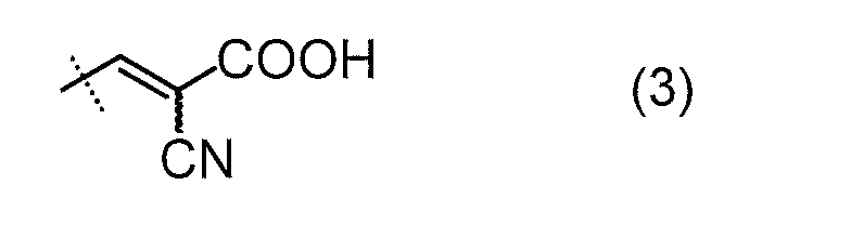
で表される2-カルボキシル-2-シアノエテニル基であることが好ましく、置換基を有してもよい炭素数1~3のアルキル基であることがより好ましく、無置換の炭素数1~3のアルキル基であることがさらに好ましく、無置換のメチル基であることが最も好ましい。
前記一般式(1)中のR2およびR3は、水素原子、ハロゲン原子、置換基を有してもよい炭素数1~4の脂肪族炭化水素基、置換基を有してもよいフェニル基、置換基を有してもよいフェノキシ基、置換基を有してもよいチエニル基、置換基を有してもよいチエノキシ基、前記式(2)で表される2-カルボキシルエテニル基、または前記式(3)で表される2-カルボキシル-2-シアノエテニル基であることが好ましく、水素原子、臭素原子、またはヨウ素原子である(ただしR2およびR3の少なくとも一方が臭素原子またはヨウ素原子である)ことがより好ましく、水素原子またはヨウ素原子である(ただしR2およびR3の少なくとも一方がヨウ素原子である)ことがさらに好ましい。
前記一般式(1)中のR5は、水素原子、ハロゲン原子、置換基を有してもよい炭素数1~4の脂肪族炭化水素基、置換基を有してもよいフェニル基、置換基を有してもよいフェノキシ基、置換基を有してもよいチエニル基、置換基を有してもよいチエノキシ基、前記式(2)で表される2-カルボキシルエテニル基、または前記式(3)で表される2-カルボキシル-2-シアノエテニル基であることが好ましく、置換基を有してもよいフェニル基であることがより好ましく、無置換またはアルキル置換のフェニル基であることがさらに好ましい。
前記一般式(1)中のR6は、ハロゲン原子、置換基を有してもよい炭素数1~5のアルキル基、または置換基を有してもよい炭素数1~5のアルコキシル基であるが、フッ素原子であることが好ましい。
前記有機光増感分子(A)は、前記一般式(5)で表される金属ポルフィリン類、または前記一般式(1)で表される化合物であることが好ましく、前記一般式(1)で表される化合物であることがより好ましく、前記一般式(1)で表される化合物において前記一般式(1)中のR1~R5がそれぞれ独立に、水素原子、ハロゲン原子、置換基を有してもよい炭素数1~4の脂肪族炭化水素基、置換基を有してもよいフェニル基、置換基を有してもよいフェノキシ基、置換基を有してもよいチエニル基、置換基を有してもよいチエノキシ基、前記式(2)で表される2-カルボキシルエテニル基、または前記式(3)で表される2-カルボキシル-2-シアノエテニル基である化合物であることがさらに好ましく、下記一般式(4)

(前記式中、R1およびR4はそれぞれ独立に置換基を有してもよい炭素数1~3のアルキル基を表し、R2およびR3はそれぞれ独立に水素原子、臭素原子、またはヨウ素原子を表し、R2およびR3の少なくとも一方が臭素原子またはヨウ素原子であり、R5は置換基を有してもよいフェニル基を表す)
で表される化合物であることが最も好ましい。これにより、さらに高い光波長変換効率を有する光波長変換要素を実現できる。
で表される化合物であることが最も好ましい。これにより、さらに高い光波長変換効率を有する光波長変換要素を実現できる。
前記一般式(1)で表される化合物としては、具体的には、下記式
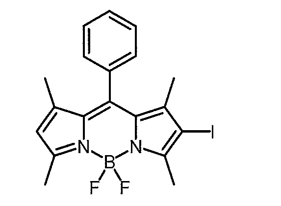
で表される化合物(2-ヨード-1,3,5,7-テトラメチル-8-フェニル-4,4-ジフルオロボラジアザインダセン)(吸収極大波長510nm)、下記式

で表される化合物(2,6-ジヨード-1,3,5,7-テトラメチル-8-フェニル-4,4-ジフルオロボラジアザインダセン)(吸収極大波長529nm)、下記式
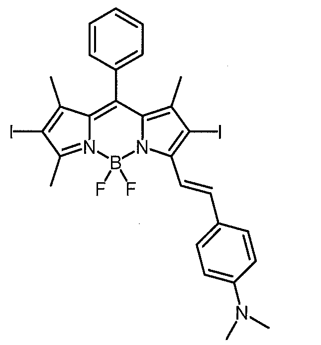
で表される化合物(吸収極大波長629nm)、下記式
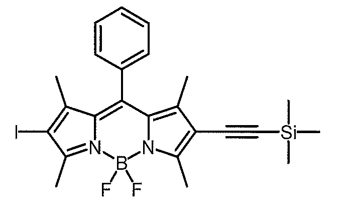
で表される化合物(吸収極大波長539nm)、下記式

で表される化合物(吸収極大波長557nm)、下記式
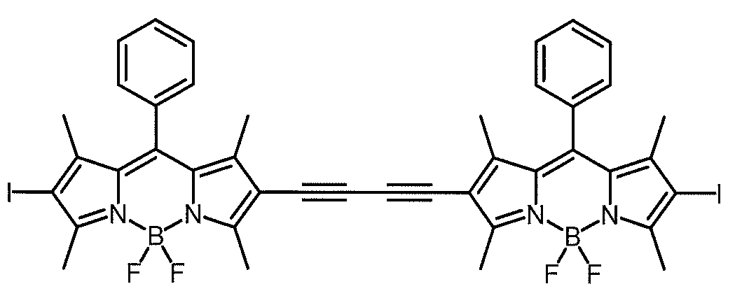
で表される化合物(吸収極大波長576nm)、下記式

で表される化合物(吸収極大波長575nmおよび618nm)、下記式

で表される化合物(吸収極大波長532nm)、下記式

で表される化合物(吸収極大波長526nm)等が挙げられる。これら有機光増感分子(A)は、1種を用いてもよく、2種以上を混合して用いてもよい。
前記有機発光分子(B)としては、前記有機光増感分子(A)と共に使用することでTTA過程により光アップコンバージョンされた光を発することのできる有機化合物であれば、特に限定されることなく使用することができる。前記有機発光分子(B)としては、例えば、アセナフテン誘導体、アセトフェノン誘導体、アントラセン誘導体、ジフェニルアセチレン誘導体、アクリダン誘導体、アクリジン誘導体、アクリドン誘導体、チオアクリドン誘導体、アンゲリシン誘導体、アントラセン誘導体、アントラキノン誘導体、アザフルオレン誘導体、アズレン誘導体、ベンジル誘導体、カルバゾール誘導体、コロネン誘導体、スマネン誘導体、ビフェニレン誘導体、フルオレン誘導体、ペリレン誘導体、フェナントレン誘導体、フェナントロリン誘導体、フェナジン誘導体、ベンゾフェノン誘導体、ピレン誘導体、ベンゾキノン誘導体、ビアセチル誘導体、ビアントラニル誘導体、フラーレン誘導体、グラフェン誘導体、カロテン誘導体、クロロフィル誘導体、クリセン誘導体、シンノリン誘導体、クマリン誘導体、クルクミン誘導体、ダンシルアミド誘導体、フラボン誘導体、フルオレノン誘導体、フルオレセイン誘導体、ヘリセン誘導体、インデン誘導体、ルミクロム誘導体、ルミフラビン誘導体、オキサジアゾール誘導体、オキサゾール誘導体、ペリフランテン誘導体、ペリレン誘導体、フェナントレン誘導体、フェナントロリン誘導体、フェナジン誘導体、フェノール誘導体、フェノチアジン誘導体、フェノキサジン誘導体、フタラジン誘導体、フタロシアニン誘導体、ピセン誘導体、ポルフィリン誘導体、ポルフィセン誘導体、ヘミポルフィセン誘導体、サブフタロシアニン誘導体、プソラレン誘導体、アンゲリシン誘導体、プリン誘導体、ピレン誘導体、ピロメテン誘導体、ピリジルケトン誘導体、フェニルケトン誘導体、ピリジルケトン誘導体、チエニルケトン誘導体、フラニルケトン誘導体、キナゾリン誘導体、キノリン誘導体、キノキサリン誘導体、レチナール誘導体、レチノール誘導体、ローダミン誘導体、リボフラビン誘導体、ルブレン誘導体、スクアリン誘導体、スチルベン誘導体、テトラセン誘導体、ペンタセン誘導体、アントラキノン誘導体、テトラセンキノン誘導体、ペンタセンキノン誘導体、チオホスゲン誘導体、インジゴ誘導体、チオインゾゴ誘導体、チオキサンテン誘導体、チミン誘導体、トリフェニレン誘導体、トリフェニルメタン誘導体、トリアリール誘導体、トリプトファン誘導体、ウラシル誘導体、キサンテン誘導体、フェロセン誘導体、アズレン誘導体、ビアセチル誘導体、ターフェニル誘導体、ターフラン誘導体、ターチオフェン誘導体、オリゴアリール誘導体、フラーレン誘導体、共役ポリエン誘導体、含14族元素縮合多環芳香族化合物誘導体、縮合多環複素芳香族化合物誘導体等が挙げられるが、これらに限定されるわけではない。
前記有機発光分子(B)としては、具体的には、例えば、9,10-ジフェニルアントラセン(CAS番号:1499-10-1)およびその誘導体、9,10-ビス(フェニルエチニル)アントラセン(CAS番号:10075-85-1)およびその誘導体(例えば1-クロロ-9,10-ビス(フェニルエチニル)アントラセン)、ペリレン(CAS番号:198-55-0)およびその誘導体(例えばペリレンジイミド)、ピレンおよびその誘導体、ルブレンおよびその誘導体、ナフタレンおよびその誘導体(例えばナフタレンジイミド、パーフルオロナフタレン、1-シアノナフタレン、1-メトキシナフタレン)、9,10-ビス(フェニルエチニル)ナフタセン、4,4’-ビス(5-テトラアセニル)-1,1’-ビフェニレン、インドール、ベンゾフラン、ベンゾチオフェン、ビフェニル、ビフラン、ビチオフェン、4,4-ジフルオロ-4-ボラ-3a,4a-ジアザ-s-インダセン(ボロンジピロメテン)等が挙げられるが、これらに限定されない。前記有機発光分子(B)としては、ペリレン、ピレン、アントラセンのような縮合多環芳香族化合物やその誘導体が好ましい。これら有機発光分子(B)は、1種を用いてもよく、2種以上を混合して用いてもよい。
本発明の光波長変換要素中における有機光増感分子(A)および有機発光分子(B)の含有量は、特に制限はないが、光波長変換要素を100質量部とした場合、それぞれ、通常は0.000001~10質量部であり、好ましくは0.00001~5質量部であり、より好ましくは0.0001~1質量部である。
前記イオン液体(C)は、カチオンとアニオンとからなる常温溶融塩(常温(25℃)で溶融状態(液体状態)にある塩)である。一般的に、イオン液体として、カチオンとアニオンとの組み合わせによって少なくとも1,000,000種類以上の化合物が存在することが知られている。前記イオン液体(C)は、前記TTA過程を示す組み合わせである有機光増感分子(A)および有機発光分子(B)の媒体として作用し、その内部で有機光増感分子(A)および有機発光分子(B)の拡散運動を許容するものである。
本発明の光波長変換要素においては、TTA過程を示す組み合わせである有機光増感分子(A)および有機発光分子(B)を、イオン液体(C)中に溶解および/または分散させて目視上均質かつ透明にする必要があるため、前記イオン液体(C)としては、前記有機光増感分子(A)および有機発光分子(B)とカチオン-π相互作用を有し、かつ非水混和性であるものが好ましい。本明細書において、イオン液体(C)が「非水混和性」とは、25℃において、50質量%以下の水がイオン液体(C)に目視上均質かつ透明に混和する場合がある(例えば5質量%以下の水がイオン液体(C)に目視上均質かつ透明に混和する場合がある)が、50質量%超の水がイオン液体(C)に目視上均質かつ透明に混和しないことを意味する。
前記イオン液体(C)を構成するカチオンの具体例としては、例えば、窒素含有化合物カチオン、第四級ホスホニウムカチオン、スルホニウムカチオン等が挙げられる。前記窒素含有化合物カチオンとしては、例えば、イミダゾリウムカチオン、ピリジニウムカチオン等の複素環式芳香族アミンカチオン;ピペリジニウムカチオン、ピロリジニウムカチオン、ピラゾリウムカチオン、チアゾリウムカチオン、モルフォリニウムカチオン等の複素環式脂肪族アミンカチオン;第四級アンモニウムカチオン;芳香族アミンカチオン;脂肪族アミンカチオン;脂環式アミンカチオン等が挙げられる。前記イミダゾリウムカチオンとしては、例えば、1-エチル-3-メチルイミダゾリウム、1-ブチル-3-メチルイミダゾリウム、1-ヘキシル-3-メチルイミダゾリウム、1-オクチル-3-メチルイミダゾリウム等の1-アルキル-3-メチルイミダゾリウム、1-エチル-2,3-ジメチルイミダゾリウム、1-プロピル-2,3-ジメチルイミダゾリウム、1-ブチル-2,3-ジメチルイミダゾリウム、1-ペンチル-2,3-ジメチルイミダゾリウム、1-ヘキシル-2,3-ジメチルイミダゾリウム、1-ヘプチル-2,3-ジメチルイミダゾリウム、1-オクチル-2,3-ジメチルイミダゾリウム等の1-アルキル-2,3-ジメチルイミダゾリウム;1-シアノメチル-3-メチルイミダゾリウム、1-(2-ヒドロキシエチル)-3-メチルイミダゾリウム等が挙げられる。前記ピリジニウムカチオンとしては、例えば、1-ブチルピリジニウム、1-ヘキシルピリジニウム、N-(3-ヒドロキシプロピル)ピリジニウム、N-ヘキシル-4-ジメチルアミノピリジニウム等が挙げられる。前記ピペリジニウムカチオンとしては、例えば、1-(メトキシエチル)-1-メチルピペリジニウム等が挙げられる。前記ピロリジニウムカチオンとしては、例えば、1-(2-メトキシエチル)-1-メチルピロリジニウム、N-(メトキシエチル)-1-メチルピロリジニウム等が挙げられる。前記モルフォリニウムカチオンとしては、例えば、N-(メトキシエチル)-N-メチルモルフォリウム等が挙げられる。前記第四級アンモニウムカチオンとしては、例えば、N,N-ジエチル-N-メチル-N-(2-メトキシエチル)アンモニウム、N-エチル-N,N-ジメチル-2-メトキシエチルアンモニウム等が挙げられる。前記第四級ホスホニウムカチオンとしては、例えば、テトラアルキルホスホニウム、テトラフェニルホスホニウム等が挙げられる。前記スルホニウムカチオンとしては、例えば、トリアルキルスルホニウム、トリフェニルスルホニウム等が挙げられる。前記イオン液体(C)中には、これらカチオンの1種が存在していてもよく2種以上が存在していてもよい。
有機光増感分子(A)および有機発光分子(B)のイオン液体(C)中への溶解・分散安定性を考慮すると、イオン液体(C)を構成するカチオンとしては、有機光増感分子(A)および有機発光分子(B)との間に「カチオン-π相互作用」を有するものが好ましい。
前記イオン液体(C)を構成するアニオンとしては、特に限定されるものではないが、例えば、ビス(トリフルオロメチルスルホニル)イミドアニオン([N(SO2CF3)2]-)、トリス(トリフルオロメチルスルホニル)メチドアニオン([C(SO2CF3)3]-)、ヘキサフルオロホスフェートアニオン([PF6]-)、トリス(ペンタフルオロエチル)、トリフルオロホスフェートアニオン([(C2F5)3PF3]-)等のフッ素含有化合物アニオン;[BR11R12R13R14]-(このアニオン構造式および以下のアニオン構造式中において、R11、R12、R13、およびR14はそれぞれ独立して、-(CH2)nCH3(ここでnは1~9の整数を表す)で表される基、すなわち炭素数1~9の直鎖アルキル基、または、アリール基を表す)で表されるホウ素含有化合物アニオン、ビス(フルオロスルホニル)イミドアニオン([N(FSO2)2]-)等が挙げられる。前記イオン液体(C)中には、これらアニオンの1種が存在していてもよく2種以上が存在していてもよい。
一般的に、イオン液体は、イオン液体を構成するアニオンの種類によっては水と上限なく混和するが、イオン液体を構成するアニオンの種類によってはイオン液体が水とある程度以上混和しないか、またはごく微量しか混和しない。本発明においては、有機光増感分子(A)および有機発光分子(B)のイオン液体(C)中への溶解・分散安定性を考慮すると、イオン液体(C)のアニオンが、イオン液体に非水混和性を与えるようなアニオンであることが好ましい。
前記イオン液体(C)としては、前記アニオンの具体例と前記カチオンの具体例とを組み合わせたものを用いることができる。前記イオン液体(C)としては、より具体的には、例えば、1-エチル-3-メチルイミダゾリウムビス(トリフルオロメチルスルホニル)イミド(CAS番号:174899-82-2、例えば製造元がIonic Liquids Technologies GmbHの市販品を入手可能)、1-プロピル-2,3-ジメチルイミダゾリウムビス(トリフルオロメチルスルホニル)イミド(CAS番号:169051-76-7、例えば製造元がIonic Liquids Technologies GmbHの市販品や製造元がMerck KGaAの市販品を入手可能)、1-ブチル-3-メチルイミダゾリウムビス(トリフルオロメチルスルホニル)イミド(CAS番号:174899-83-3、例えば製造元がIonic Liquids Technologies GmbHの市販品や製造元がMerck KGaAの市販品を入手可能)、1-プロピル-2,3-ジメチルイミダゾリウムトリス(トリフルオロメチルスルホニル)メチド(CAS番号:169051-77-8、例えば製造元がCovalent Associates Inc.の市販品を入手可能)、N,N-ジエチル-N-メチル-N-(2-メトキシエチル)アンモニウムビス(トリフルオロメチルスルホニル)イミド(CAS番号:464927-84-2、例えば製造元が日清紡績株式会社で販売元が関東化学株式会社の市販品(製品番号:11468-55)を入手可能)、1-ヘキシル-3-メチルイミダゾリウムビス(トリフルオロメチルスルホニル)イミド(CAS番号:382150-50-7、例えば製造元がMerck KGaAの市販品を入手可能)、1-オクチル-3-メチルイミダゾリウムビス(トリフルオロメチルスルホニル)イミド(CAS番号:178631-04-4、例えば製造元が日清紡績株式会社で販売元が関東化学株式会社の市販品(製品番号:49514-85)を入手可能)、1-エチル-2,3-ジメチルイミダゾリウムビス(トリフルオロメチルスルホニル)イミド(CAS番号:174899-90-2、例えば販売元が関東化学株式会社の市販品(製品番号:49515-52)を入手可能)、1-ブチル-2,3-ジメチルイミダゾリウムビス(トリフルオロメチルスルホニル)イミド(CAS番号:350493-08-2、例えば製造元がIonic Liquids Technologies GmbHの市販品や製造元がMerck KGaAの市販品を入手可能)、エチルジメチルプロピルアンモニウムビス(トリフルオロメチルスルホニル)イミド(CAS番号:258273-77-7、例えば製造元がMerck KGaAの市販品を入手可能)、1-エチル-3-メチルイミダゾリウムトリス(ペンタフルオロエチル)トリフルオロホスフェート(CAS番号:377739-43-0、例えば製造元がMerck KGaAの市販品を入手可能)、1-ヘキシル-3-メチルイミダゾリウムトリス(ペンタフルオロエチル)トリフルオロホスフェート(CAS番号:713512-19-7、例えば製造元がMerck KGaAの市販品を入手可能)、1-ブチル-1-メチルピロリジニウムビス(トリフルオロメチルスルホニル)イミド(CAS番号:223437-11-4、例えば製造元がMerck KGaAの市販品を入手可能)、1-ブチル-1-メチルピロリジニウムトリス(ペンタフルオロエチル)トリフルオロホスフェート(CAS番号:851856-47-8、例えば製造元がMerck KGaAの市販品を入手可能)、メチルトリ-n-オクチルアンモニウムビス(トリフルオロメチルスルホニル)イミド(CAS番号:375395-33-8、例えば製造元がMerck KGaAの市販品を入手可能)、1-エチル-3-メチルイミダゾリウムトリス(トリフルオロメチルスルホニル)メチド、1-ブチル-3-メチルイミダゾリウムトリス(トリフルオロメチルスルホニル)メチド、1-ヘキシル-3-メチルイミダゾリウムトリス(トリフルオロメチルスルホニル)メチド、1-オクチル-3-メチルイミダゾリウムトリス(トリフルオロメチルスルホニル)メチド、1-ブチル-2,3-ジメチルイミダゾリウムトリス(トリフルオロメチルスルホニル)メチド、N,N-ジエチル-N-メチル-N-(2-メトキシエチル)アンモニウムトリス(トリフルオロメチルスルホニル)メチド、1-ブチル-3-メチルイミダゾリウムトリス(ペンタフルオロエチル)トリフルオロホスフェート、1-オクチル-3-メチルイミダゾリウムトリス(ペンタフルオロエチル)トリフルオロホスフェート、1-プロピル-2,3-ジメチルイミダゾリウムトリス(ペンタフルオロエチル)トリフルオロホスフェート、1-ブチル-2,3-ジメチルイミダゾリウムトリス(ペンタフルオロエチル)トリフルオロホスフェート、N,N-ジエチル-N-メチル-N-(2-メトキシエチル)アンモニウムトリス(ペンタフルオロエチル)トリフルオロホスフェート、1-エチル-3-メチルイミダゾリウムヘキサフルオロホスフェート、1-ブチル-3-メチルイミダゾリウムヘキサフルオロホスフェート、1-ヘキシル-3-メチルイミダゾリウムヘキサフルオロホスフェート、1-オクチル-3-メチルイミダゾリウムヘキサフルオロホスフェート、1-プロピル-2,3-ジメチルイミダゾリウムヘキサフルオロホスフェート、1-ブチル-2,3-ジメチルイミダゾリウムヘキサフルオロホスフェート、N,N-ジエチル-N-メチル-N-(2-メトキシエチル)アンモニウムヘキサフルオロホスフェート、1-エチル-3-メチルイミダゾリウム[BR11R12R13R14]-、1-ブチル-3-メチルイミダゾリウム[BR11R12R13R14]-、1-ヘキシル-3-メチルイミダゾリウム[BR11R12R13R14]-、1-オクチル-3-メチルイミダゾリウム[BR11R12R13R14]-、1-プロピル-2,3-ジメチルイミダゾリウム[BR11R12R13R14]-、1-ブチル-2,3-ジメチルイミダゾリウム[BR11R12R13R14]-、N,N-ジエチル-N-メチル-N-(2-メトキシエチル)アンモニウム[BR11R12R13R14]-、1-ブチルピリジニウムヘキサフルオロホスフェート、1-ヘキシルピリジニウムヘキサフルオロホスフェート、1-シアノメチル-3-メチルイミダゾリウムビス(トリフルオロメチルスルホニル)イミド、N-ヘキシル-4-ジメチルアミノピリジニウムビス(トリフルオロメチルスルホニル)イミド、1-(2-ヒドロキシエチル)-3-メチルイミダゾリウムビス(トリフルオロメチルスルホニル)イミド、N-(3-ヒドロキシプロピル)ピリジニウムビス(トリフルオロメチルスルホニル)イミド、N-エチル-N,N-ジメチル-2-メトキシエチルアンモニウムトリス(ペンタフルオロエチル)トリフルオロホスフェート、1-(2-ヒドロキシエチル)-3-メチルイミダゾリウムトリス(ペンタフルオロエチル)トリフルオロホスフェート、N-(3-ヒドロキシプロピル)ピリジニウムトリス(ペンタフルオロエチル)トリフルオロホスフェート、N-(メトキシエチル)-N-メチルモルフォリウムトリス(ぺンタフルオロエチル)トリフルオロホスフェート、1-(2-メトキシエチル)-1-メチル-ピロリジニウムトリス(ペンタフルオロエチル)トリフルオロホスフェート、1-(メトキシエチル)-1-メチルピペリジニウムトリス(ペンタフルオロエチル)トリフルオロホスフェート、1-(メトキシエチル)-1-メチルピペリジニウムビス(トリフルオロメチルスルホニル)イミド、N-(メトキシエチル)-1-メチルピロリジニウムビス(トリフルオロメチルスルホニル)イミド、N-(メトキシエチル)-N-メチルモルフォリウムビス(トリフルオロメチルスルホニル)等が挙げられるが、これらに限定されない。これらイオン液体(C)は、1種を用いてもよく、2種以上を混合して用いてもよい。
本発明においては、有機光増感分子(A)および有機発光分子(B)のイオン液体(C)中への溶解・分散の安定性を考慮すると、これらイオン液体(C)のうち、有機光増感分子(A)および有機発光分子(B)との間に「カチオン-π相互作用」を有するカチオンと、イオン液体に非水混和性を与えるアニオンとの組み合わせが好ましく、イオン液体(C)としても非水混和性のものが好ましい。
前記イオン液体(C)としては、上に挙げた具体例のうちで、1-エチル-3-メチルイミダゾリウムビス(トリフルオロメチルスルホニル)イミド、1-プロピル-2,3-ジメチルイミダゾリウムビス(トリフルオロメチルスルホニル)イミド、1-ブチル-3-メチルイミダゾリウムビス(トリフルオロメチルスルホニル)イミド、1-プロピル-2,3-ジメチルイミダゾリウムトリス(トリフルオロメチルスルホニル)メチド、N,N-ジエチル-N-メチル-N-(2-メトキシエチル)アンモニウムビス(トリフルオロメチルスルホニル)イミド、1-ヘキシル-3-メチルイミダゾリウムビス(トリフルオロメチルスルホニル)イミド、1-オクチル-3-メチルイミダゾリウムビス(トリフルオロメチルスルホニル)イミド、1-エチル-2,3-ジメチルイミダゾリウムビス(トリフルオロメチルスルホニル)イミド、1-ブチル-2,3-ジメチルイミダゾリウムビス(トリフルオロメチルスルホニル)イミド、エチルジメチルプロピルアンモニウムビス(トリフルオロメチルスルホニル)イミド、1-エチル-3-メチルイミダゾリウムトリス(ペンタフルオロエチル)トリフルオロホスフェート、1-ヘキシル-3-メチルイミダゾリウムトリス(ペンタフルオロエチル)トリフルオロホスフェート、1-ブチル-1-メチルピロリジニウムビス(トリフルオロメチルスルホニル)イミド、1-ブチル-1-メチルピロリジニウムトリス(ペンタフルオロエチル)トリフルオロホスフェート、およびメチルトリ-n-オクチルアンモニウムビス(トリフルオロメチルスルホニル)イミドが特に好ましい。
前記イオン液体(C)の26℃における粘度は、通常は10mPa・s以上であり、好ましくは50mPa・s以上であり、より好ましくは70mPa・s以上である。これにより、より高い光波長変換効率を有する光波長変換要素を実現できる。
本発明の光波長変換要素に含まれるイオン液体(C)は、イオン液体をその9倍の体積の超純水で洗浄したときに、洗浄後の水のpHが5より大きくなるものである。これにより、より高い光波長変換効率及びより良好な経時安定性を有する光波長変換要素を実現できる。イオン液体(C)をその9倍の体積の超純水で洗浄したときにおける、洗浄後の水のpHの測定方法としては、イオン液体(C)に対してその9倍の体積(体積比でその9倍量)の超純水を入れて撹拌した後に、水層を分離し、水層のpHを測定する方法を用いる。
市販のイオン液体は、イオン液体をその9倍の体積の超純水で洗浄したときに洗浄後の水のpHが5以下の酸性を示すことが多い。そのような市販のイオン液体を使用する場合には、市販のイオン液体から不純物を除去することにより、その9倍の体積の超純水で洗浄したときに洗浄後の水のpHが5より大きくなるようなイオン液体(C)を得て、そのイオン液体(C)を使用する必要がある。
前記イオン液体からの不純物除去方法としては、例えば、(1)イオン液体を活性炭で処理する方法、(2)イオン液体を水で洗浄する方法、(3)イオン液体を有機溶媒で洗浄する方法(例えば特開2012-144441号公報参照)、(4)イオン液体を溶媒に溶解させて溶液を得た後、前記溶液の温度を下げて前記イオン液体を溶液中から結晶させ、結晶した前記イオン液体を濾過により溶液から分離する方法(再結晶法;例えば特開2010-184902号公報参照)、(5)イオン液体を溶媒に溶解させて溶液を得た後、アルミナ等の充填剤を充填したカラムに前記溶液を通す方法(カラム法;例えば特開2005-314332号公報)、(6)イオン液体を金属水素化物で処理する方法(特開2005-89313号公報参照)等が挙げられる。これらの方法を複数組み合わせて使用してもよい。前記(2)の方法としては、例えば、イオン液体に水(好ましくは超純水)を加えて撹拌した後で水層を除去する洗浄処理を洗浄後の水のpHが5より大きくなるまで繰り返し、次いで、減圧下で加熱することにより水を留去する(乾燥する)方法を用いることができる。
本発明の光波長変換要素は、通常公知の技術を用いて有機光増感分子(A)および有機発光分子(B)をイオン液体(C)中に溶解および/または分散させて溶液または分散液を得る方法によって製造することができる。前記方法において、必要に応じて、通常公知の技術を用いてその他の添加剤をイオン液体(C)中で有機光増感分子(A)および有機発光分子(B)に混合して、溶液または分散液を得てもよい。また、前記方法において、必要に応じて、超音波分散機、ビーズミル、ホモジナイザー、湿式ジェットミル、ボールミル、アトライター、サンドミル、ロールミル、マイクロ波分散機等の公知の分散機を単独または組み合わせて使用し、有機光増感分子(A)および有機発光分子(B)を微粉砕、微分散して、溶液または分散液を得てもよい。
また、本発明の光波長変換要素を製造する他の方法として、例えば、まず、有機光増感分子(A)および有機発光分子(B)を揮発性有機溶媒中に溶解および/または分散させ、次に、得られた溶液および/または分散体をイオン液体(C)と撹拌混合して目視上均質かつ透明な溶液および/または分散体を生成させ、さらにその溶液および/または分散体から減圧下でこの揮発性有機溶媒を痕跡量以下まで除去する方法を用いることもできる。この方法は、均質かつ透明に混和した状態の光波長変換要素を得られやすく、安定性や光波長変換効率の高い光波長変換要素を得ることができるので、本発明の光波長変換要素を得る方法としてより好ましい。
前記方法に用いる揮発性有機溶媒は、有機光増感分子(A)および有機発光分子(B)を溶解および/または分散させることができ、かつイオン液体(C)と均質かつ透明に混和でき、さらに減圧下で痕跡量程度まで除去できるような揮発性を有する有機溶媒であれば、特に制限はない。ここで、「痕跡量」とは、光吸収スペクトルの測定に基づいてイオン液体(C)中に混在する揮発性有機溶媒をノイズレベル以下でしか検出できない量とする。前記揮発性有機溶媒は、有機光増感分子(A)および有機発光分子(B)を溶解させることができる揮発性有機溶媒であることが好ましい。前記揮発性有機溶媒としては、トルエン、ベンゼン、キシレン等の芳香族系溶媒等を用いることができる。有機光増感分子(A)および有機発光分子(B)を溶解させることができる揮発性有機溶媒を使用する場合、その揮発性有機溶媒は有機光増感分子および有機発光分子の溶解性に合わせて適宜選択できる。
前記撹拌混合の手段としては、超音波、バブリング、撹拌機、液送ポンプ、粉砕機、ビーズミル、ホモジナイザー、湿式ジェットミル、マイクロ波等の公知の技術または装置を用いることができる。これらの手段は、1種を使用してもよく、2種以上を組み合わせて使用してもよい。
本発明の光波長変換要素は、ゲル化剤(D)をさらに含んでいてもよい。前記構成の光波長変換要素は、ゲル化剤(D)を含むので、ゲル化剤(D)を含まない場合と比較して流動性が抑制されており、太陽電池、光触媒、光触媒型水素・酸素発生装置、光アップコンバージョンフィルター等の物品に使用されたときに光波長変換要素光波長変換要素の漏洩が起こり難い。
ゲル化剤(D)をさらに含む本発明の光波長変換要素は、ゲル状態となっていることが好ましい。これにより、太陽電池、光触媒、光触媒型水素・酸素発生装置、光アップコンバージョンフィルター等の物品に使用されたときに、さらに漏洩し難い光波長変換要素を実現できる。
前記ゲル化剤(D)としては、イオン液体(C)に溶解し、有機光増感分子(A)の吸光および有機発光分子(B)の発光を阻害しない程度の光透過性を有するゲルを形成できるものであれば特に限定されるものではないが、十分な光透過性を有するゲルを形成できることから、イオン性ゲル化剤、非イオン性重合体が好ましく、少ない添加量のゲル化剤(D)で簡便にゲルを形成できることから、イオン性ゲル化剤がより好ましい。
前記イオン性ゲル化剤としては、下記一般式
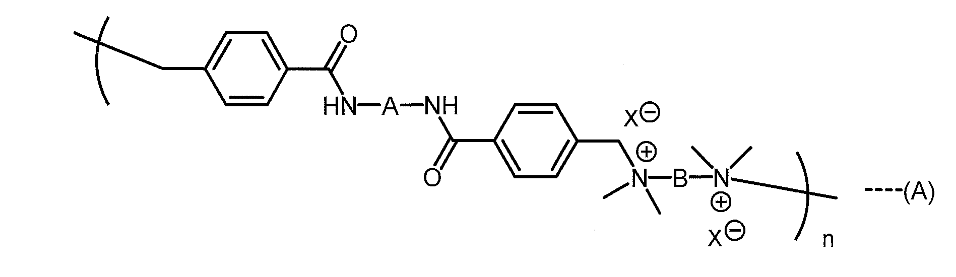
(前記式中、Aは置換基を有してもよい芳香環を1個以上有する2価基又はシクロヘキサンジイル基を表し、Bは置換基を有してもよい炭素数が1~10のアルキレン基を表し、X-は1価のアニオンを表し、nは各分子内では正の整数を表し、全分子のnの平均値が1~800である)
で表される化合物が好ましい。
で表される化合物が好ましい。
前記シクロヘキサンジイル基は、例えばシクロヘキサン-1,4-ジイル基である。前記一般式(A)中のBは、置換基を有してもよい炭素数が1~6のアルキレン基であることが好ましく、置換基を有してもよい炭素数が2~6のアルキレン基であることがより好ましい。前記アルキレン基が有してもよい置換基としては、メチル、エチル、プロピル基等の炭素数1~6のアルキル基;メトキシ、エトキシ、プロポキシ基等の炭素数1~6のアルコキシ基等が挙げられる。前記一般式(A)中のBの具体例としては、例えば、メチレン基、エタン-1,2-ジイル基、プロパン-1,4-ジイル基、ブタン-1,4-ジイル基、ヘキサン-1,6-ジイル基、2-ブテン-1,4-ジイル基等が挙げられる。
前記一般式(A)中のX-としては、限定されるものではないが、例えば、ハロゲン化物イオン(F-、Cl-、Br-、又はI-)、ビス(トリフルオロメタンスルホニル)アミドイオン、ビス(フルオロスルホニル)アミドイオン、テトラフルオロホウ酸イオン(BF4
-)、ヘキサフルオロリン酸イオン(PF6
-)、チオシアン酸イオン(SCN-)、硝酸イオン(NO3
-)、メト硫酸イオン(CH3OSO3‐)、炭酸水素イオン(HCO3
-)、次亜リン酸イオン(H2PO2
-)、ハロゲンのオキソ酸イオン(YO4
-、YO3
-、YO2
-、又はYO-;YはCl、Br、又はIを表す)、トリス(トリフルオロメタンスルホニル)炭素酸イオン、トリフルオロメタンスルホン酸イオン、ジシアナミドイオン、酢酸イオン(CH3COO-)、ハロゲン化酢酸イオン((CZnH3-n)COO-;ZはF、Cl、Br、又はIを表し、nは1、2、又は3である)、テトラフェニルホウ酸イオン(BPh4
-)およびその誘導体(B(Aryl)4
-;Arylは置換フェニル基を表す)等が挙げられる。前記一般式(A)中のX-としては、ビス(トリフルオロメタンスルホニル)アミドイオン、ビス(フルオロスルホニル)アミドイオン、テトラフルオロホウ酸イオン(BF4
-)が好ましい。
前記一般式(A)で表される化合物の好ましい例としては、下記一般式

(前記各式中、Bは、エチレン基、1,3-プロピレン基、1,4-ブチレン基、又は1,6-ヘキサレン基を表し、X-は、ハロゲン化物イオン(F-、Cl-、Br-、又はI-)、ビス(トリフルオロメタンスルホニル)アミドイオン、ビス(フルオロスルホニル)アミドイオン、テトラフルオロホウ酸イオン(BF4
-)、ヘキサフルオロリン酸イオン(PF6
-)、チオシアン酸イオン(SCN-)、硝酸イオン(NO3
-)、メト硫酸イオン(CH3OSO3‐)、炭酸水素イオン(HCO3
-)、次亜リン酸イオン(H2PO2
-)、ハロゲンのオキソ酸イオン(YO4
-、YO3
-、YO2
-、又はYO-;YはCl、Br、又はIを表す)、トリス(トリフルオロメタンスルホニル)炭素酸イオン、トリフルオロメタンスルホン酸イオン、ジシアナミドイオン、酢酸イオン(CH3COO-)、ハロゲン化酢酸イオン((CZnH3-n)COO-;ZはF、Cl、Br、又はIを表し、nは1、2、又は3である)、テトラフェニルホウ酸イオン(BPh4
-)およびその誘導体(B(Aryl)4
-;Arylは置換フェニル基を表す)から選ばれる少なくとも1種を表し、nは各分子内では正の整数を表し、全分子のnの平均値が1~800である)
で表される化合物、下記一般式
で表される化合物、下記一般式

(前記各式中のBは、式(A1)~(A6)中のBと同じものを表す)
で表される化合物、下記一般式
で表される化合物、下記一般式
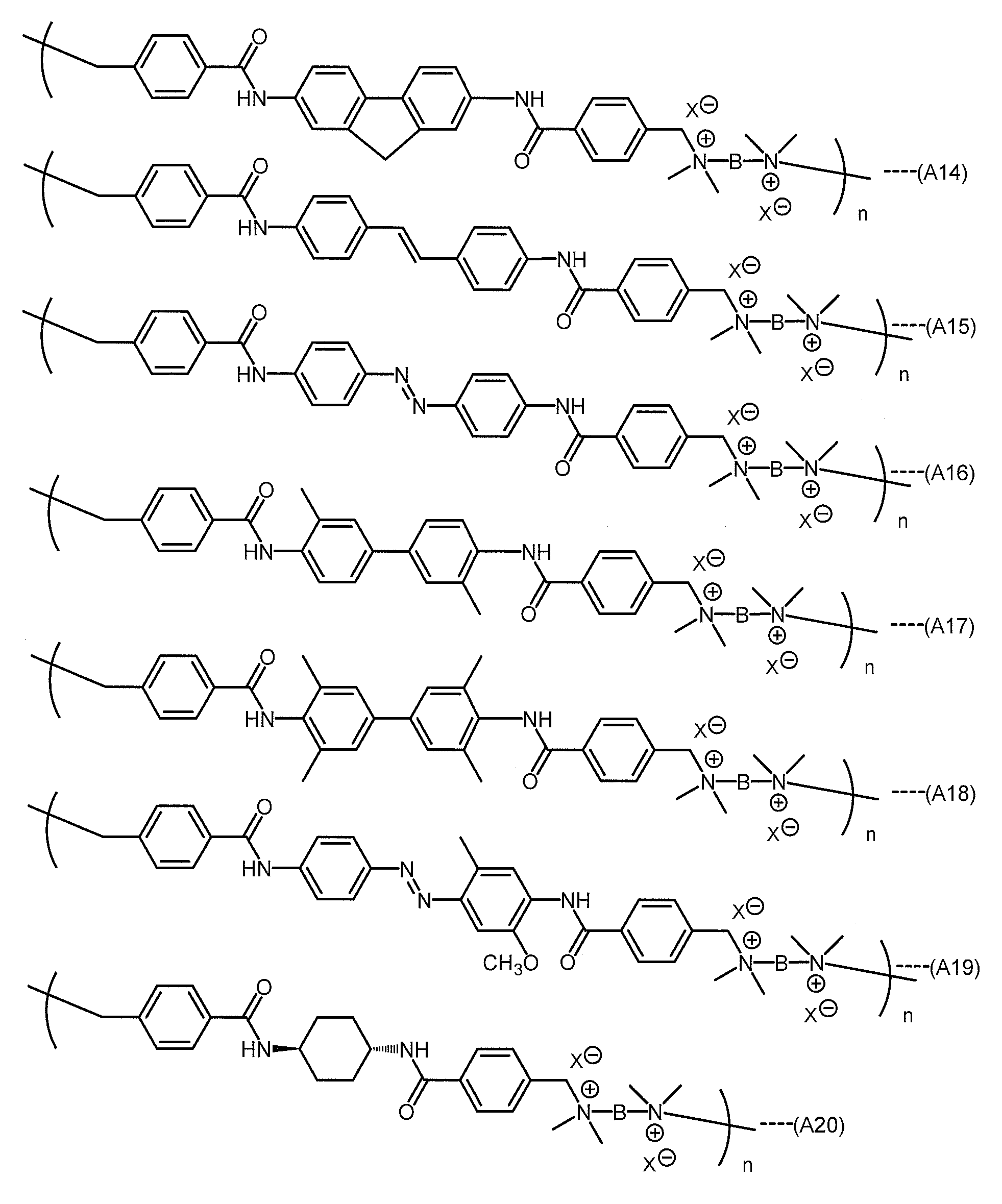
(前記各式中のBは、式(A1)~(A6)中のBと同じものを表す)
で表される化合物等が挙げられる。
で表される化合物等が挙げられる。
本発明の光波長変換要素におけるイオン性ゲル化剤の濃度は、イオン性ゲル化剤のnの値等にもよるが、通常0.3~100g/Lであり、好ましくは0.5~60gであり、より好ましくは1~20gである。イオン性ゲル化剤の濃度が0.3g/L未満である場合、光波長変換要素が十分にゲル化しない恐れがある。イオン性ゲル化剤の濃度が100g/Lを超える場合、イオン性ゲル化剤がイオン液体(C)に溶解して形成されるゲルの光透過性が低くなり、光波長変換要素の光波長変換特性が低下する恐れがある。
前記非イオン性重合体としては、後段で詳細に説明する重合反応により非イオン性重合体を形成可能な化合物の少なくとも1種の重合体を用いることができる。前記非イオン性重合体の吸光度は、低い方が好ましい。
ゲル化剤(D)を含む本発明の光波長変換要素は、ゲル化剤(D)がイオン性ゲル化剤である場合には、例えば、(1)有機光増感分子(A)および有機発光分子(B)をイオン液体(C)中に溶解および/または分散させてなる溶液および/または分散液を、イオン性ゲル化剤及びイオン液体(C)の混合物(溶液又はゲル)と混合する方法、(2)有機光増感分子(A)および有機発光分子(B)をイオン液体(C)中に溶解および/または分散させてなる溶液および/または分散液を、イオン性ゲル化剤を有機溶媒に溶解させてなる溶液と混合した後、有機溶媒を留去する方法等の方法を用いて製造することができる。前記(1)および(2)の方法のうちで前記(1)の方法が、光波長変換要素中に有機溶媒が残留することを回避することができ、よりしっかりしたゲル状態の光波長変換要素を得ることが可能となるため、より好ましい。
前記の有機光増感分子(A)および有機発光分子(B)をイオン液体(C)中に溶解および/または分散させてなる溶液および/または分散液は、例えば、有機光増感分子(A)を揮発性有機溶媒に溶解させて有機光増感分子(A)の溶液を調製し、また、有機発光分子(B)を揮発性有機溶媒に溶解させて有機光増感分子(B)の溶液を調製し、有機光増感分子(A)の溶液と、有機光増感分子(B)の溶液と、イオン液体(C)とを混合し撹拌により均一化する方法で製造することができる。
前記のイオン性ゲル化剤及びイオン液体(C)の混合物は、例えば、イオン性ゲル化剤を揮発性有機溶媒に溶解および/または分散させた後にイオン液体(C)と混合して加熱し減圧下で揮発性有機溶媒を留去する方法、イオン性ゲル化剤とイオン液体(C)とを混合して加熱する方法等を用いて製造することができる。これら方法のうち、前者の方法が、比較的低い温度(例えば90℃以下)での加熱でイオン性ゲル化剤をイオン液体(C)に混合して溶液又はゲルにすることができるため、比較的高い温度(例えば140℃以上)での加熱がしばしば要される後者の方法と比較して、加熱による混合物の着色などの変質を抑制できるので、好ましい。
前記のイオン性ゲル化剤をイオン液体(C)の混合物の製造に用いる揮発性有機溶媒は、イオン性ゲル化剤を溶解および/または分散させることができ、かつイオン液体(C)と均質かつ透明に混和でき、さらに減圧下で痕跡量程度まで除去できるような揮発性を有する有機溶媒であれば、特に制限はない。ここで、「痕跡量」とは、光吸収スペクトルの測定に基づいてイオン液体(C)中に混在する揮発性有機溶媒をノイズレベル以下でしか検出できない量とする。前記揮発性有機溶媒は、イオン性ゲル化剤を溶解させることができる揮発性有機溶媒であることが好ましい。前記揮発性有機溶媒としては、例えば、メタノール等のアルコール系溶媒等を用いることができる。
ゲル化剤(D)を含む本発明の光波長変換要素は、ゲル化剤(D)が非イオン性重合体である場合には、例えば、(I)有機光増感分子(A)および有機発光分子(B)とが溶解および/または分散された、揮発性有機溶媒とイオン液体(C)との混合溶液および/または分散液を、非イオン性重合体に含浸させた後、減圧下で揮発性有機溶媒を除去する方法、(II)前記の有機光増感分子(A)および有機発光分子(B)をイオン液体(C)中に溶解および/または分散させてなる溶液および/または分散液と、重合反応により非イオン性重合体を形成可能な化合物(以下「重合性化合物」と呼ぶ;後段で詳細に説明する)とを混合した後、前記重合性化合物の重合反応を行うことにより非イオン性重合体を形成する方法等の方法を用いて製造することができる。
前記の有機光増感分子(A)および有機発光分子(B)を揮発性有機溶媒およびイオン液体(C)中に溶解および/または分散させてなる溶液および/または分散液は、例えば、有機光増感分子(A)を揮発性有機溶媒に溶解させて有機光増感分子(A)の溶液を調製し、また、有機発光分子(B)を揮発性有機溶媒に溶解させて有機光増感分子(B)の溶液を調製し、有機光増感分子(A)の溶液と、有機光増感分子(B)の溶液と、イオン液体(C)とを混合し撹拌により均一化する方法で製造することができる。また、有機光増感分子(A)の溶液と、有機光増感分子(B)の溶液と、イオン液体(C)とを混合する順序は特に限定されるものではなく、例えば、イオン液体(C)に対して、有機光増感分子(B)の溶液を混合した後、有機光増感分子(A)の溶液と有機光増感分子(B)の溶液とを混合することもできる。
前記(I)の「混合溶液および/または分散液」においては、有機光増感分子(A)と有機発光分子(B)はそれぞれ、揮発性有機溶媒とイオン液体(C)のどちらか一方のみに溶解および/または分散していてもよいし、任意の比率で揮発性有機溶媒とイオン液体(C)の両方に溶解および/または分散していてもよい。
前記(1)(2)(II)の方法に用いる、有機光増感分子(A)および有機発光分子(B)をイオン液体(C)中に溶解および/または分散させてなる溶液および/または分散液は、通常公知の技術を用いて有機光増感分子(A)および有機発光分子(B)をイオン液体(C)中に溶解および/または分散させる方法によって製造することができる。前記方法において、必要に応じて、通常公知の技術を用いてその他の添加剤をイオン液体(C)中で有機光増感分子(A)および有機発光分子(B)に混合して、前記溶液および/または分散液を得てもよい。また、前記方法において、必要に応じて、超音波分散機、ビーズミル、ホモジナイザー、湿式ジェットミル、ボールミル、アトライター、サンドミル、ロールミル、マイクロ波分散機等の公知の分散機を単独または組み合わせて使用し、有機光増感分子(A)および有機発光分子(B)を微粉砕、微分散して、前記溶液および/または分散液を得てもよい。
また、前記(1)(2)(II)の方法に用いる、有機光増感分子(A)および有機発光分子(B)をイオン液体(C)中に溶解および/または分散させてなる溶液および/または分散液を製造する第2の方法として、例えば、まず、有機光増感分子(A)および有機発光分子(B)を揮発性有機溶媒中に溶解および/または分散させ、次に、得られた溶液および/または分散体をイオン液体(C)と撹拌混合して目視上均質かつ透明な溶液および/または分散体を生成させ、さらにその溶液および/または分散体から減圧下でこの揮発性有機溶媒を痕跡量以下まで除去する方法を用いることもできる。この方法は、均質かつ透明に混和した状態の光波長変換要素を得られやすく、安定性や光波長変換効率の高い光波長変換要素を得ることができるので、有機光増感分子(A)および有機発光分子(B)をイオン液体(C)中に溶解および/または分散させてなる溶液または分散液を得る方法としてより好ましい。
前記(I)の方法や前記第2の方法に用いる、揮発性有機溶媒は、有機光増感分子(A)および有機発光分子(B)を溶解および/または分散させることができ、かつイオン液体(C)と均質かつ透明に混和でき、さらに減圧下で痕跡量程度まで除去できるような揮発性を有する有機溶媒であれば、特に制限はない。ここで、「痕跡量」とは、光吸収スペクトルの測定に基づいてイオン液体(C)中に混在する揮発性有機溶媒をノイズレベル以下でしか検出できない量とする。前記揮発性有機溶媒は、有機光増感分子(A)および有機発光分子(B)を溶解させることができる揮発性有機溶媒であることが好ましい。前記揮発性有機溶媒としては、トルエン、ベンゼン、キシレン等の芳香族系溶媒等を用いることができる。有機光増感分子(A)および有機発光分子(B)を溶解させることができる揮発性有機溶媒を使用する場合、その揮発性有機溶媒は有機光増感分子および有機発光分子の溶解性に合わせて適宜選択できる。
前記(I)の方法や第2の方法における撹拌混合の手段としては、超音波、バブリング、撹拌機、液送ポンプ、粉砕機、ビーズミル、ホモジナイザー、湿式ジェットミル、マイクロ波等の公知の技術または装置を用いることができる。これらの手段は、1種を使用してもよく、2種以上を組み合わせて使用してもよい。
本発明の光波長変換要素において非イオン性ゲル化剤を用いる場合、十分にゲル化させるためにはイオン性ゲル化剤を用いる場合と比較してゲル化剤(D)の使用量が通常は多くなるが、光波長変換要素全体を100質量部とした場合のイオン液体(C)の含有量は、通常10質量部以上であり、好ましくは30質量部以上である。
前記(I)の方法に用いる、非イオン性重合体としては、特に限定されるものではないが、有機光増感分子(A)および有機発光分子(B)をイオン液体(C)中に溶解および/または分散させてなる溶液または分散液を吸収して膨潤し易いことから、非イオン性のアクリル樹脂が好ましい。前記非イオン性のアクリル樹脂は、メチルメタアクリレート、メチルアクリレート、ブチルアクリレート、ヒドロキシエチルメタクリレート等の(メタ)アクリレート((メタ)アクリル酸エステル)類を主成分とする非イオン性単量体の重合体である。なお、本明細書において、「(メタ)アクリレート」はアクリレート及び/又はメタクリレートを意味し、「(メタ)アクリル」はアクリル及び/又はメタクリルを意味するものとする。また、前記(I)の方法に用いる非イオン性重合体は、どのような形状であってもよいが、例えばフィルム形状とすることができる。
前記(II)の方法に用いる重合性化合物は、熱重合反応により非イオン性重合体を形成可能な化合物であってもよく、光重合反応により非イオン性重合体を形成可能な化合物であってもよい。
前記の熱重合反応により非イオン性重合体を形成可能な化合物としては、例えば、メチルメタクリレート、メチルアクリレート、ブチルアクリレート、ヒドロキシエチルメタクリレート等の非イオン性の(メタ)アクリル酸エステル類;アクリロニトリル、メタクリロニトリル等の非イオン性の(メタ)アクリロニトリル類;スチレン、α-メチルスチレン、p-メトキシスチレン、p-シアノスチレン等の非イオン性のスチレン類;ビニルアセテート等の非イオン性のカルボン酸ビニル類;塩化ビニル、塩化ビニリデン等の非イオン性の塩素含有単量体;アクリルアミド等の非イオン性の(メタ)アクリルアミド類;テトラフロオロエチレン等の非イオン性のフッ素含有単量体;メチルビニルケトン等の非イオン性のビニルケトン類;エチレン等のオレフィン類等の単量体が挙げられる。これらは、1種を単独で用いてもよく、2種以上を混合して用いてもよい。なお、本明細書において、「(メタ)アクリロニトリル」はアクリロニトリル及び/又はメタクリロニトリルを意味するものとする。
これら化合物を用いて非イオン性の重合体を形成するには、前記の熱重合反応により非イオン性重合体を形成可能な化合物に、アゾ化合物、有機過酸化物等のラジカル熱重合開始剤等を添加して、前記化合物の熱重合反応を行えばよい。
また、前記の熱重合反応により非イオン性重合体を形成可能な化合物としては、他にも、エポキシ樹脂類が挙げられる。前記エポキシ樹脂類としては、例えば、脂肪族環状構造をもつエポキシ樹脂、ビスフェノールA型エポキシ樹脂、分子内に3個以上のエポキシ基を有する芳香族多官能エポキシ樹脂等を用いることができる。前記エポキシ樹脂類を用いて非イオン性重合体を形成するには、酸無水物、酸無水物誘導体、イミダゾール類等の塩基性硬化剤等を用いて前記エポキシ樹脂類を熱硬化すればよい。この方法では、硬化後の着色の少ない非イオン性重合体を得ることができる。
前記の光重合反応により非イオン性重合体を形成可能な化合物としては、例えば、ビニル基、ビニルエーテル基、アリル基、マレイミド基、(メタ)アクリロイル基等の重合性基を有する単量体が挙げられるが、中でも(メタ)アクリロイル基を有する単量体が、反応性の点で好ましい。前記の(メタ)アクリロイル基を有する単量体としては、例えば、構造中に(メタ)アクリロイル基を一つ有する単官能(メタ)アクリレート単量体;(メタ)アクリロイル基を2つ有する2官能(メタ)アクリレート単量体;3つ以上のアクリロイル基を有する3官能以上の多官能(メタ)アクリレート単量体等の(メタ)アクリレート単量体が挙げられる。なお、本明細書において、「(メタ)アクリロイル」はアクリロイル及び/又はメタクリロイルを意味するものとする。
前記単官能(メタ)アクリレート単量体としては、例えば、フェノキシエチル(メタ)アクリレート、フェニル(ポリ)エトキシ(メタ)アクリレート、p-クミルフェノキシエチル(メタ)アクリレート、トリブロモフェニルオキシエチル(メタ)アクリレート、フェニルチオエチル(メタ)アクリレート、2-ヒドロキシ-3-フェニルオキシプロピル(メタ)アクリレート、フェニルフェノール(ポリ)エトキシ(メタ)アクリレート、フェニルフェノールエポキシ(メタ)アクリレート、アクリロイルモルホリン、2-ヒドロキシプロピル(メタ)アクリレート、4-ヒドロキシブチル(メタ)アクリレート、シクロヘキサン-1,4-ジメタノールモノ(メタ)アクリレート、テトラヒドロフルフリル(メタ)アクリレート、イソボルニル(メタ)アクリレート、ジシクロペンタニル(メタ)アクリレート、ジシクロペンテニル(メタ)アクリレート、ジシクロペンテニルオキシエチル(メタ)アクリレート等を挙げることができる。なお、本明細書において、「(ポリ)エトキシ」はエトキシ及び/又はポリエトキシを意味するものとする。
前記2官能(メタ)アクリレート単量体としては、1,4-ブタンジオールジ(メタ)アクリレート、1,6-ヘキサンジオールジ(メタ)アクリレート、1,9-ノナンジオールジ(メタ)アクリレート、トリシクロデカンジメタノールジ(メタ)アクリレート、ビスフェノールAポリエトキシジ(メタ)アクリレート、ビスフェノールAポリプロポキシジ(メタ)アクリレート、ビスフェノールFポリエトキシジ(メタ)アクリレート、エチレングリコールジ(メタ)アクリレート、ポリエチレングリコールジ(メタ)アクリレート、ヒドロキシビバリン酸ネオペンチルグリコールのε-カプロラクトン付加物のジ(メタ)アクリレート(例えば、日本化薬株式会社製のKAYARAD(登録商標)HX-220、KAYARAD(登録商標)HX-620等)等を挙げることができる。
前記の3官能以上の多官能(メタ)アクリレート単量体としては、トリス(アクリロキシエチル)イソシアヌレート、ペンタエリスリトールテトラ(メタ)アクリレート、ジペンタエリスリトールヘキサ(メタ)アクリレート、ジペンタエリスリトールペンタ(メタ)アクリレート、トリペンタエリスリトールヘキサ(メタ)アクリレート、トリペンタエリスリトールペンタ(メタ)アクリレート、トリメチロールプロパントリ(メタ)アクリレート、トリメチロールプロパンポリエトキシトリ(メタ)アクリレート、ジトリメチロールプロパンテトラ(メタ)アクリレート等を挙げることができる。
さらには、前記の(メタ)アクリロイル基を有する単量体として、ウレタン(メタ)アクリレート、エポキシ(メタ)アクリレート、ポリエステル(メタ)アクリレート等の(メタ)アクリレートオリゴマーを用いることができる。これらは、1種を単独で用いてもよく、2種以上を混合して用いてもよい。
前記の光重合反応により非イオン性重合体を形成可能な化合物を用いて非イオン性重合体を形成するには、前記の光重合反応により非イオン性重合体を形成可能な化合物に、ベンゾイン類、アセトフェノン類、アントラキノン類、チオキサントン類、ケタール類、ベンゾフェノン類、ホスフィンオキサイド類等の1種または2種以上の光重合開始剤を添加し、紫外線を照射することで前記化合物の光重合反応を行えばよい。
本発明の光波長変換要素は、その水分量が、1質量%以下であることが好ましく、0.1質量%以下であることがより好ましく、0.01質量%以下であることがさらに好ましく、0.001質量%以下であることが最も好ましい。これにより、より高い光波長変換効率を有する光波長変換要素を実現できる。
また、本発明の光波長変換要素は、その酸素濃度が、100質量ppm以下であることが好ましく、10質量ppm以下であることがより好ましく、1質量ppm以下であることがさらに好ましく、0.1質量ppm以下であることが最も好ましい。これにより、より高い光波長変換効率を有する光波長変換要素を実現できる。
本発明の光波長変換要素は、目視上均質かつ透明な溶液および/または分散体であり、さらに安定性も良好である。本発明の光波長変換要素は、太陽電池、光触媒、光触媒型水素・酸素発生装置、光アップコンバージョンフィルター等に用いることができる。
本発明の太陽電池は、本発明の光波長変換要素を用いたものである。
本発明の太陽電池の一例を、図1に基づいて説明する。本発明の一例に係る太陽電池は、図1に示すように、光電変換層(太陽電池層)1と、光電変換層1における光入射側の面上に配設された短冊状の受光面電極7と、光電変換層1における光入射側の面の裏面上に積層された透明背面電極2と、透明背面電極2における光入射側の面の裏面上に積層された透明絶縁膜3と、透明絶縁膜3における光入射側の面の裏面上に積層された、本発明の光波長変換要素を用いたアップコンバージョン層4と、アップコンバージョン層4における光入射側の面の裏面上に積層された光反射膜5とを備えている。
光電変換層1としては、特に限定されるものではなく、色素増感太陽電池や有機薄膜太陽電池等の有機系光電変換層、化合物半導体系光電変換層、シリコン系光電変換層等を用いることができる。
受光面電極7および光反射膜5は、Ag、Al、Ti、Cr、Mo、W、Ni、Cu等の金属で形成することができる。透明背面電極2は、ITO(酸化インジウムスズ)、SnO2、ZnO等の透明導電体で形成することができる。透明絶縁膜3は、ポリエチレンテレフタレート、ポリカーボネート、ポリイミド樹脂、アクリル樹脂、およびポリエーテルニトリル等の樹脂で形成することができる。
アップコンバージョン層4は、後述する本発明の光アップコンバージョンフィルターと同様に、セルと、セル中に封入された光波長変換要素とで形成されていてもよく、光波長変換要素のみで形成されていてもよい。アップコンバージョン層4が光波長変換要素のみで形成されている場合、透明絶縁膜3、アップコンバージョン層4、および光反射膜5をそれらの周縁で封止樹脂等の封止部材により封止すればよい。
図1の構成により、太陽からの入射光6を、アップコンバージョン層4がアップコンバートする(より短い波長の光に変換する)ことにより、光電変換層1が発電に使用できる波長範囲の光の強度を高めて、太陽電池の発電効率をさらに高めることができる。
なお、図1の構成では、アップコンバージョン層4を透明絶縁膜3と光反射膜5との間に配置していたが、アップコンバージョン層4の配置位置を、受光面電極7における光入射側等のような他の配置位置に変更してもよい。その場合には、アップコンバージョン層4と受光面電極7との間に透明絶縁膜を設けてもよい。
また、図1の太陽電池において、受光面電極7を、光電変換層1における光入射側の面の全体に形成された透明電極に置き換えてもよい。また、図1の太陽電池において、透明絶縁膜3を省略してもよい。ただし、アップコンバージョン層4が光波長変換要素のみで形成されている場合には、光波長変換要素と透明背面電極2との接触を避けるために透明絶縁膜3を光波長変換要素と透明背面電極2との間に配置することが好ましい。また、図1の太陽電池において、アップコンバージョン層4の配置位置を受光面電極7における光入射側に変更し、かつ透明絶縁膜3を省略した場合には、透明背面電極2を光反射電極に置き換えて光反射膜5を省略してもよい。
本発明の光触媒は、本発明の光波長変換要素を用いたものである。例えば、図1の太陽電池における受光面電極7、光電変換層1、透明背面電極2、および透明絶縁膜3に代えて、光触媒層を配置することにより、触媒効率の高い、光触媒を実現することができる。
本発明の一例に係る光触媒は、図2に示すように、光触媒が添加された水10(光触媒層)が収容され、光触媒が添加された水10以外の空間にガス9が充填されたガラスチャンネル8と、ガラスチャンネル8の側面上および底面上に形成されたアップコンバージョン層4と、アップコンバージョン層4の外側の面上に形成された光反射膜5と、光反射膜5を支持するために光反射膜5の外側の面上に形成された機械的支持体11とを備えている。
図2の構成により、太陽からの入射光6を、アップコンバージョン層4がアップコンバートする(より短い波長の光に変換する)ことにより、水10に添加された光触媒が触媒反応に使用できる波長範囲の光の強度を高めて、光触媒の変換効率をさらに高めることができる。
本発明の光触媒型水素・酸素発生装置は、本発明の光波長変換要素を用いたものである。例えば、図1の太陽電池における受光面電極7、光電変換層1、透明背面電極2、および透明絶縁膜3に代えて、光触媒層を配置することにより、水素・酸素発生効率の高い光触媒型水素・酸素発生装置を実現することができる。
また、本発明の光アップコンバージョンフィルターは、光をより短い波長の光に変換する光アップコンバージョンフィルターであって、前記光波長変換要素と、セルとを備えている。
前記セルとしては、光を透過しうるセルであれば特に限定されるものではないが、例えば、石英ガラス、ホウケイ酸ガラス等からなる2枚のガラス板を重ね合わせてそれらの周縁部を融着接合した構成のセルを用いることができる。
前記光波長変換要素は、その酸素濃度が、100質量ppm以下の状態で前記セル中に封入されていることが好ましく、10質量ppm以下の状態で前記セル中に封入されていることがより好ましく、1質量ppm以下の状態で前記セル中に封入されていることがさらに好ましく、0.1質量ppm以下の状態で前記セル中に封入されていることが最も好ましい。前記光波長変換要素が、その酸素濃度が100質量ppm以下の状態で前記セル中に封入されている場合、酸素濃度が低い状態に保たれている。その結果、太陽光強度程度の弱い光にも適用可能な高い光波長変換効率を安定して示す光アップコンバージョンフィルターを実現できる。
前記光アップコンバージョンフィルターは、例えば、光波長変換要素をセル中に注入し、必要に応じてその酸素濃度が100質量ppm以下となるまで脱酸素処理を行った後、セルを封止する方法によって得ることができる。前記脱酸素処理の方法としては、例えば、ロータリーポンプやターボ分子ポンプ等の真空ポンプを用いて光波長変換要素を減圧処理する方法、窒素ガスやアルゴンガス等の不活性ガスを光波長変換要素中にバブリングさせる方法、光波長変換要素を凍結させた後で真空ポンプを用いて減圧処理(真空脱気)する方法(凍結真空脱気法)等が挙げられる。
前記光アップコンバージョンフィルターは、前記太陽電池、光触媒、光触媒型水素・酸素発生装置のアップコンバージョン層4として利用することができる。
なお、本発明の光波長変換要素を用いた太陽電池、光触媒、光触媒型水素・酸素発生装置、光アップコンバージョンフィルター等の物品においては、光波長変換要素の酸素濃度を低減するために酸素ゲッターを共存させてもよい。また、本発明の光波長変換要素を用いた太陽電池、光触媒、光触媒型水素・酸素発生装置、光アップコンバージョンフィルター等の物品においては、光波長変換要素の酸素濃度を低減するために水吸収材料を共存させてもよい。
次に、実施例により本発明を更に詳細に説明する。なお、本発明は以下の実施例によって何ら限定されるものではない。以下のイオン液体(C)の作製例で用いる超純水については以下の通りである。
〔超純水の製造〕
以下のイオン液体(C)の作製例では、超純水として、超純水製造装置(製造元:Merck KGaA、型番:Direct-Q(登録商標)UV3)で製造した超純水を用いた。
以下のイオン液体(C)の作製例では、超純水として、超純水製造装置(製造元:Merck KGaA、型番:Direct-Q(登録商標)UV3)で製造した超純水を用いた。
〔有機光増感分子(A)の合成例1〕
非特許文献6に記載の方法で、下記式
非特許文献6に記載の方法で、下記式

で表される有機光増感分子(A)(2-ヨード-1,3,5,7-テトラメチル-8-フェニル-4,4-ジフルオロボラジアザインダセン)を合成した。得られた化合物の同定は、以下のNMRスペクトルにより行った。
1H NMR(400MHz,CDCl3):δ 7.51-7.48(m,3H),7.27-7.25(m,2H),6,04(s,1H),2.63(s,3H),2.57(s,3H),1.38(s,6H)
13C NMR(100MHz,CDCl3):δ 157.9,154.7,145.3,143.4,141.7,135.0,132.0,131.1,129.8,129.5,129.4,128.0,122.5,84.4,16.8,16.0,14.9,14.7
〔有機光増感分子(A)の合成例2〕
非特許文献6に記載の方法で、下記式
1H NMR(400MHz,CDCl3):δ 7.51-7.48(m,3H),7.27-7.25(m,2H),6,04(s,1H),2.63(s,3H),2.57(s,3H),1.38(s,6H)
13C NMR(100MHz,CDCl3):δ 157.9,154.7,145.3,143.4,141.7,135.0,132.0,131.1,129.8,129.5,129.4,128.0,122.5,84.4,16.8,16.0,14.9,14.7
〔有機光増感分子(A)の合成例2〕
非特許文献6に記載の方法で、下記式

で表される有機光増感分子(A)(2,6-ジヨード-1,3,5,7-テトラメチル-8-フェニル-4,4-ジフルオロボラジアザインダセン)を合成した。得られた化合物の同定は、以下のNMRスペクトルにより行った。
1H NMR(400MHz,CDCl3):δ 7.54-7.51(m,3H),7.26-7.24(m,2H),2.65(s,6H),1.38(s,6H)
13C NMR(100MHz,CDCl3):δ 156.9,145.5,141.5,134.4,129.7,129.6,127.9,85.8,17.1,16.2
〔イオン液体(C)の作製例1〕
非水混和性のイオン液体である1-プロピル-2,3-ジメチルイミダゾリウムビス(トリフルオロメチルスルホニル)イミド(CAS番号:169051-76-7;以下「イオン液体#1」と称する)の市販品(製造元:Ionic Liquids Technologies GmbH)をガラスバイアル瓶にとり、そのイオン液体#1の市販品にその9倍の体積の超純水を加え、汎用のマグネチックスターラーおよび撹拌子を用いて撹拌し静置した(その9倍の体積の超純水により洗浄した)。このとき、ガラスバイアル瓶の内容物は、ガラスバイアル瓶の底部にある当該イオン液体層と、その上にある水層とに分離した。その後、水層を取得し、水層のpH(洗浄後の水のpH)を測定したところ、水層のpHは3.9であった。
1H NMR(400MHz,CDCl3):δ 7.54-7.51(m,3H),7.26-7.24(m,2H),2.65(s,6H),1.38(s,6H)
13C NMR(100MHz,CDCl3):δ 156.9,145.5,141.5,134.4,129.7,129.6,127.9,85.8,17.1,16.2
〔イオン液体(C)の作製例1〕
非水混和性のイオン液体である1-プロピル-2,3-ジメチルイミダゾリウムビス(トリフルオロメチルスルホニル)イミド(CAS番号:169051-76-7;以下「イオン液体#1」と称する)の市販品(製造元:Ionic Liquids Technologies GmbH)をガラスバイアル瓶にとり、そのイオン液体#1の市販品にその9倍の体積の超純水を加え、汎用のマグネチックスターラーおよび撹拌子を用いて撹拌し静置した(その9倍の体積の超純水により洗浄した)。このとき、ガラスバイアル瓶の内容物は、ガラスバイアル瓶の底部にある当該イオン液体層と、その上にある水層とに分離した。その後、水層を取得し、水層のpH(洗浄後の水のpH)を測定したところ、水層のpHは3.9であった。
一方、このイオン液体#1の市販品1mLを内容量約8mLのガラスバイアル瓶にとり、イオン液体#1の市販品に活性炭30mgを加え、真空乾燥オーブン(製造元:ヤマト科学株式会社、型番:ADP200)中で140℃にて3時間真空乾燥した。真空乾燥オーブンからガラスバイアル瓶を取り出した後、遠心分離を行い、活性炭を殆ど含まない上澄み部分を取得した。取得した上澄み部分を、孔径約0.2μmの使い捨てシリンジフィルター(製造元:Merck KGaA、型番:IC Millex(登録商標)-LG)に通して残存する活性炭を除去し、内容量約20mLのガラスバイアル瓶内に注いだ。ガラスバイアル瓶の内容物にその9倍の体積の超純水を加え、汎用のマグネチックスターラーおよび撹拌子を用いて5分間撹拌し数分間静置した後に水層を除去する、という洗浄操作を、3回繰り返した。3回目の洗浄操作で除去された水層のpH(洗浄後の水のpH)を測定したところ、水層のpHは6.5であった。
最後に、ガラスバイアル瓶内に残った水層をガラス製パスツールピペット(製造元:Fisher Scientific Inc.、製品番号:5-5351-01)で可能な限り取り除いた。ガラスバイアル瓶の内容物(イオン液体層)を強制対流乾燥オーブン(販売元:アドバンテック東洋株式会社、製造元:東洋製作所、型番:DRM320DB)にて70℃で一晩乾燥した後、さらに真空乾燥オーブン(先の真空乾燥に使用したものと同じ)にて120℃で3時間真空乾燥し、イオン液体(C)であるイオン液体#1を得た。
〔イオン液体(C)の作製例2〕
イオン液体(C)の作製例1で用いたイオン液体#1の市販品に代えて非水混和性のイオン液体である1-ブチル-2,3-ジメチルイミダゾリウムビス(トリフルオロメチルスルホニル)イミド(CAS番号:350493-08-2;以下「イオン液体#2」と称する)の市販品(製造元:Ionic Liquids Technologies GmbH)を用いる以外は、イオン液体(C)の作製例1と同様の処理(イオン液体の9倍の体積の超純水による洗浄(撹拌および水層除去)の3回繰り返し)を行った。その結果、3回目の洗浄操作で除去された水層のpH(洗浄後の水のpH)が6.4となり、イオン液体(C)であるイオン液体#2が得られた。
イオン液体(C)の作製例1で用いたイオン液体#1の市販品に代えて非水混和性のイオン液体である1-ブチル-2,3-ジメチルイミダゾリウムビス(トリフルオロメチルスルホニル)イミド(CAS番号:350493-08-2;以下「イオン液体#2」と称する)の市販品(製造元:Ionic Liquids Technologies GmbH)を用いる以外は、イオン液体(C)の作製例1と同様の処理(イオン液体の9倍の体積の超純水による洗浄(撹拌および水層除去)の3回繰り返し)を行った。その結果、3回目の洗浄操作で除去された水層のpH(洗浄後の水のpH)が6.4となり、イオン液体(C)であるイオン液体#2が得られた。
〔イオン液体(C)の作製例3〕
イオン液体(C)の作製例1および2と同様の処理をそれぞれ行うことにより、イオン液体(C)である、イオン液体#1およびイオン液体#2を得た。また、イオン液体(C)の作製例1で用いたイオン液体#1の市販品に代えて、すべて非水混和性のイオン液体である、1-エチル-3-メチルイミダゾリウムビス(トリフルオロメチルスルホニル)イミド(CAS番号:174899-82-2;以下「イオン液体#3」と称する)の市販品(製造元:Ionic Liquids Technologies GmbH)、1-ブチル-3-メチルイミダゾリウムビス(トリフルオロメチルスルホニル)イミド(CAS番号:174899-83-3;以下「イオン液体#4」と称する)の市販品(製造元:Ionic Liquids Technologies GmbH)、1-ブチル-3-メチルイミダゾリウムビス(トリフルオロメチルスルホニル)イミド(CAS番号:174899-83-3;以下「イオン液体#5」と称する)の市販品(製造元:Merck KGaA)、エチルジメチルプロピルアンモニウムビス(トリフルオロメチルスルホニル)イミド(CAS番号:258273-77-7;以下「イオン液体#6」と称する)の市販品(製造元:Merck KGaA)、1-プロピル-2,3-ジメチルイミダゾリウムビス(トリフルオロメチルスルホニル)イミド(CAS番号:169051-76-7;以下「イオン液体#7」と称する)の市販品(製造元:Merck KGaA)、1-エチル-3-メチルイミダゾリウムトリス(ペンタフルオロエチル)トリフルオロホスフェート(CAS番号:377739-43-0;以下「イオン液体#8」と称する)の市販品(製造元:Merck KGaA)、1-ヘキシル-3-メチルイミダゾリウムトリス(ペンタフルオロエチル)トリフルオロホスフェート(CAS番号:713512-19-7;以下「イオン液体#9」と称する)の市販品(製造元:Merck KGaA)、1-ブチル-1-メチルピロリジニウムビス(トリフルオロメチルスルホニル)イミド(CAS番号:223437-11-4;以下「イオン液体#10」と称する)の市販品(製造元:Merck KGaA)、1-ブチル-2,3-ジメチルイミダゾリウムビス(トリフルオロメチルスルホニル)イミド(CAS番号:350493-08-2;以下「イオン液体#11」と称する)の市販品(製造元:Merck KGaA)、1-ヘキシル-3-メチルイミダゾリウムビス(トリフルオロメチルスルホニル)イミド(CAS番号:382150-50-7;以下「イオン液体#12」と称する)の市販品(製造元:Merck KGaA)、1-ブチル-1-メチルピロリジニウムトリス(ペンタフルオロエチル)トリフルオロホスフェート(CAS番号:851856-47-8;以下「イオン液体#13」と称する)の市販品(製造元:Merck KGaA)、およびメチルトリ-n-オクチルアンモニウムビス(トリフルオロメチルスルホニル)イミド(CAS番号:375395-33-8;以下「イオン液体#14」と称する)の市販品(製造元:Merck KGaA)をそれぞれ用いる以外は、イオン液体(C)の作製例1と同様の処理を行うことにより、イオン液体(C)である、イオン液体#3、イオン液体#4、イオン液体#5、イオン液体#6、イオン液体#7、イオン液体#8、イオン液体#9、イオン液体#10、イオン液体#11、イオン液体#12、イオン液体#13、およびイオン液体#14を得た。
イオン液体(C)の作製例1および2と同様の処理をそれぞれ行うことにより、イオン液体(C)である、イオン液体#1およびイオン液体#2を得た。また、イオン液体(C)の作製例1で用いたイオン液体#1の市販品に代えて、すべて非水混和性のイオン液体である、1-エチル-3-メチルイミダゾリウムビス(トリフルオロメチルスルホニル)イミド(CAS番号:174899-82-2;以下「イオン液体#3」と称する)の市販品(製造元:Ionic Liquids Technologies GmbH)、1-ブチル-3-メチルイミダゾリウムビス(トリフルオロメチルスルホニル)イミド(CAS番号:174899-83-3;以下「イオン液体#4」と称する)の市販品(製造元:Ionic Liquids Technologies GmbH)、1-ブチル-3-メチルイミダゾリウムビス(トリフルオロメチルスルホニル)イミド(CAS番号:174899-83-3;以下「イオン液体#5」と称する)の市販品(製造元:Merck KGaA)、エチルジメチルプロピルアンモニウムビス(トリフルオロメチルスルホニル)イミド(CAS番号:258273-77-7;以下「イオン液体#6」と称する)の市販品(製造元:Merck KGaA)、1-プロピル-2,3-ジメチルイミダゾリウムビス(トリフルオロメチルスルホニル)イミド(CAS番号:169051-76-7;以下「イオン液体#7」と称する)の市販品(製造元:Merck KGaA)、1-エチル-3-メチルイミダゾリウムトリス(ペンタフルオロエチル)トリフルオロホスフェート(CAS番号:377739-43-0;以下「イオン液体#8」と称する)の市販品(製造元:Merck KGaA)、1-ヘキシル-3-メチルイミダゾリウムトリス(ペンタフルオロエチル)トリフルオロホスフェート(CAS番号:713512-19-7;以下「イオン液体#9」と称する)の市販品(製造元:Merck KGaA)、1-ブチル-1-メチルピロリジニウムビス(トリフルオロメチルスルホニル)イミド(CAS番号:223437-11-4;以下「イオン液体#10」と称する)の市販品(製造元:Merck KGaA)、1-ブチル-2,3-ジメチルイミダゾリウムビス(トリフルオロメチルスルホニル)イミド(CAS番号:350493-08-2;以下「イオン液体#11」と称する)の市販品(製造元:Merck KGaA)、1-ヘキシル-3-メチルイミダゾリウムビス(トリフルオロメチルスルホニル)イミド(CAS番号:382150-50-7;以下「イオン液体#12」と称する)の市販品(製造元:Merck KGaA)、1-ブチル-1-メチルピロリジニウムトリス(ペンタフルオロエチル)トリフルオロホスフェート(CAS番号:851856-47-8;以下「イオン液体#13」と称する)の市販品(製造元:Merck KGaA)、およびメチルトリ-n-オクチルアンモニウムビス(トリフルオロメチルスルホニル)イミド(CAS番号:375395-33-8;以下「イオン液体#14」と称する)の市販品(製造元:Merck KGaA)をそれぞれ用いる以外は、イオン液体(C)の作製例1と同様の処理を行うことにより、イオン液体(C)である、イオン液体#3、イオン液体#4、イオン液体#5、イオン液体#6、イオン液体#7、イオン液体#8、イオン液体#9、イオン液体#10、イオン液体#11、イオン液体#12、イオン液体#13、およびイオン液体#14を得た。
得られたイオン液体(C)であるイオン液体#1~#14のそれぞれの一部に対して、その9倍の体積の超純水を加え、汎用のマグネチックスターラーおよび撹拌子を用いて5分間撹拌し数分間静置した後、水層を取得し、水層のpH(洗浄後の水のpH)を測定したところ、何れの場合にも水層のpHは5より大きかった。
〔イオン液体(C)中での有機光増感分子(A)の溶解安定性の確認〕
有機光増感分子(A)の合成例2で得られた有機光増感分子(A)(2,6-ジヨード-1,3,5,7-テトラメチル-8-フェニル-4,4-ジフルオロボラジアザインダセン)を、イオン液体(C)中に目視上均質かつ透明に溶解および/または分散させることができ、かつ、その状態が安定に保たれることを確認するため、以下の実験を行った。
有機光増感分子(A)の合成例2で得られた有機光増感分子(A)(2,6-ジヨード-1,3,5,7-テトラメチル-8-フェニル-4,4-ジフルオロボラジアザインダセン)を、イオン液体(C)中に目視上均質かつ透明に溶解および/または分散させることができ、かつ、その状態が安定に保たれることを確認するため、以下の実験を行った。
まず、内容積約8mLのガラスバイアル瓶を3個用意し、それぞれのガラスバイアル瓶内に、イオン液体(C)の作製例1に準じて予め洗浄水のpHが5より大きくなるように調製したイオン液体(C)であるイオン液体#1、イオン液体#3、およびイオン液体#12を各300μLずつ入れた。
続いて、これらの3つのガラスバイアル瓶内にそれぞれ、有機光増感分子(A)の合成例2で得られた有機光増感分子(A)(2,6-ジヨード-1,3,5,7-テトラメチル-8-フェニル-4,4-ジフルオロボラジアザインダセン)をトルエン中に濃度3×10⁻⁴Mで溶解させた溶液を100μLずつ加えた。そして、これらのガラスバイアル瓶の内容物に対してガラス製パスツールピペット(製造元:Fisher Scientific Inc.、製品番号:5-5351-01)を用いて「吸い・吐き」を繰り返し行って目視で均質かつ透明な混合液とした。その後、これらのガラスバイアル瓶に蓋をして、超音波バスソニケーター(製造元:Branson Ultrasonics Corp.、型番:Model3510)にて約7分間撹拌・均質化処理した。その後、各ガラスバイアル瓶の蓋を取り除き、各ガラスバイアル瓶を真空容器に入れて、スクロールポンプ(製造元:エドワーズ株式会社、型番:XDS35i、設計到達圧力:1Pa以下)を用いて室温で約8時間減圧処理を行った。その結果、トルエンが痕跡量以下まで除去された、目視上均質かつ透明な一層の溶液および/または分散体(液体)が得られた。
続いて、これら液体の安定性を確かめるため、これらの3つのガラスバイアル瓶を大気中・室温の光の当たらない棚の中で静置保管し、162時間後に棚から取り出して確認したところ、これら液体は目視上均質かつ透明な状態のままであった。さらに、これらの3種類の液体をそれぞれスライドガラス上に少量滴下し、対物レンズ倍率10倍および50倍にて顕微鏡で観察した。観察の結果、いずれの液体にも微結晶等の固体析出は全く見られず、有機光増感分子(A)の合成例2で得られた有機光増感分子(A)が、目視上均質かつ透明に、イオン液体(C)中において溶解および/または分散した状態を安定に保っていることが確認された。
〔実施例1〕
(光波長変換要素の作製)
室温下で、内容積約8mLのガラスバイアル瓶内に、イオン液体(C)の作製例1で得られたイオン液体(C)であるイオン液体#1を400μL入れた。続いて、このイオン液体(C)であるイオン液体#1に、有機光増感分子(A)としてのメソ-テトラフェニル-テトラベンゾポルフィリンパラジウム(CAS番号:119654-64-7)をトルエン中に濃度2×10⁻⁴Mで溶解させた溶液を約20μL、有機発光分子(B)としてのペリレン(CAS番号:198-55-0)をトルエン中に濃度4×10⁻³Mで溶解させた溶液を約300μL加えた。これにより、目視で不均質な混合液体が得られた。この目視で不均質な混合液体に対して、特許文献3に記載した方法と同様にガラス製パスツールピペット(イオン液体(C)の作製例1で使用したものと同じ)を用いて「吸い・吐き」を繰り返し行うことにより、目視で均質かつ透明な混合液を得た。その後、そのガラスバイアル瓶に蓋をして、超音波バスソニケーター(製造元:Branson Ultrasonics Corp.、型番:Model3510)にて約10分間撹拌および均質化処理した。
(光波長変換要素の作製)
室温下で、内容積約8mLのガラスバイアル瓶内に、イオン液体(C)の作製例1で得られたイオン液体(C)であるイオン液体#1を400μL入れた。続いて、このイオン液体(C)であるイオン液体#1に、有機光増感分子(A)としてのメソ-テトラフェニル-テトラベンゾポルフィリンパラジウム(CAS番号:119654-64-7)をトルエン中に濃度2×10⁻⁴Mで溶解させた溶液を約20μL、有機発光分子(B)としてのペリレン(CAS番号:198-55-0)をトルエン中に濃度4×10⁻³Mで溶解させた溶液を約300μL加えた。これにより、目視で不均質な混合液体が得られた。この目視で不均質な混合液体に対して、特許文献3に記載した方法と同様にガラス製パスツールピペット(イオン液体(C)の作製例1で使用したものと同じ)を用いて「吸い・吐き」を繰り返し行うことにより、目視で均質かつ透明な混合液を得た。その後、そのガラスバイアル瓶に蓋をして、超音波バスソニケーター(製造元:Branson Ultrasonics Corp.、型番:Model3510)にて約10分間撹拌および均質化処理した。
その後、ガラスバイアル瓶の蓋を取り除き、ガラスバイアル瓶を真空容器内に入れ、室温下でスクロールポンプ(製造元:エドワーズ株式会社、型番:XDS35i、設計到達圧力:1Pa以下)を用いて約8時間減圧処理を行った。その結果、揮発分であるトルエンは痕跡量以下まで除去され、目視上均質かつ透明な一層の溶液および/または分散体(液体)が得られた。さらに、このガラスバイアル瓶を、アルゴンで満たされたグローブボックス中に設置された真空チャンバー(アルミニウム製、内部寸法が直径10cm×高さ6cmの円筒形特注品)の中に設置し、専用の蓋で真空チャンバーを密閉した後、ターボ分子ポンプ(製造元:Pfeiffer Vacuum Technology AG、型番:HiCube 80、実質到達圧力:約10-4~10-5Pa)で一晩、約10-4~10-5Paの真空度にて真空引きを行うことにより、残留する酸素分子を徹底的に除去し、光波長変換要素としての目視上均質かつ透明な液体を得た。
(光波長変換要素のアップコンバージョン発光の評価)
続いて、同グローブボックス中で真空チャンバーの蓋を開け、同グローブボックス中において、特許文献3に記載した方法と同様に、当該液体(光波長変換要素)の一部を、内寸1mm×1mm、外寸2mm×2mm、長さ約25mmの片端閉じ正方形石英管内にその全長の3/4程度、注入し、石英管の開口端を鉛ハンダで封止して、当該石英管に密閉されたアップコンバージョン発光評価用試料を得た。このアップコンバージョン発光評価用試料は、光波長変換要素とセルとしての石英管とを備え、光波長変換要素が、その酸素濃度が100質量ppm以下の状態で前記石英管中に封入されているものであり、本発明の光アップコンバージョンフィルターに相当する。
続いて、同グローブボックス中で真空チャンバーの蓋を開け、同グローブボックス中において、特許文献3に記載した方法と同様に、当該液体(光波長変換要素)の一部を、内寸1mm×1mm、外寸2mm×2mm、長さ約25mmの片端閉じ正方形石英管内にその全長の3/4程度、注入し、石英管の開口端を鉛ハンダで封止して、当該石英管に密閉されたアップコンバージョン発光評価用試料を得た。このアップコンバージョン発光評価用試料は、光波長変換要素とセルとしての石英管とを備え、光波長変換要素が、その酸素濃度が100質量ppm以下の状態で前記石英管中に封入されているものであり、本発明の光アップコンバージョンフィルターに相当する。
作製したアップコンバージョン発光評価用試料を専用の試料ホルダーに固定し、励起光として、連続光レーザー発光器(製造元:CVI Melles Griot Inc.、型番:25LHP928-249)から出射させた連続光レーザー発光(波長:632.8nm、スポット径:約0.8mm、出力パワー:約28mW、以下「連続光レーザー発光#1」と称する)を照射したところ、目視で明るい青色のアップコンバージョン発光(波長475nm付近に最大ピーク)が観測された。そして、同じアップコンバージョン発光評価用試料からのアップコンバージョン発光を、入射励起光と直角の方向に集光レンズで取り出し、取り出したアップコンバージョン発光をもう一枚のレンズで分光器(製造元:Roper Scientific GmbH、型番:SP-2300i)の入口スリットに集光し、分光器の後に設置された電子冷却シリコンCCD検出器(製造元:Roper Scientific GmbH、型番:Pixis100BR)によりアップコンバージョン発光のスペクトル(スペクトル形状)および強度を測定した。測定されたアップコンバージョン発光スペクトルを図3に示す。この強度を時間に対してモニターしたところ、アップコンバージョン発光評価用試料からのアップコンバージョン発光の強度は連続光レーザー発光#1の照射時間(数分間)の間不変であり、アップコンバージョン発光評価用試料が連続光レーザー発光#1の照射に対して高い安定性を有していることが判明した。
(光波長変換要素の光吸収スペクトルの測定)
また、アップコンバージョン発光評価用試料の作製に使用しなかった残りの液体(光波長変換要素)を厚さ1mmの薄型石英セルに入れて、光吸収スペクトル測定用試料とした。紫外可視近赤外分光光度計(製造元:島津製作所、型番:UV-3600)により、光吸収スペクトル測定用試料の光吸収スペクトルを測定した。測定された光吸収スペクトルを図4に示す。
また、アップコンバージョン発光評価用試料の作製に使用しなかった残りの液体(光波長変換要素)を厚さ1mmの薄型石英セルに入れて、光吸収スペクトル測定用試料とした。紫外可視近赤外分光光度計(製造元:島津製作所、型番:UV-3600)により、光吸収スペクトル測定用試料の光吸収スペクトルを測定した。測定された光吸収スペクトルを図4に示す。
〔比較例1〕
イオン液体(C)の作製例1の方法により得られたイオン液体(C)であるイオン液体#1の代わりに、イオン液体(C)の作製例1に使用したイオン液体#1の市販品(その9倍の体積の超純水で洗浄した後に洗浄後の水のpHが3.9であるもの)をそのまま用いる以外は、実施例1と同じ手順で比較用の光波長変換要素としての目視上均質かつ透明な液体を作製し、実施例1と同じ手順で比較用のアップコンバージョン発光評価用試料を作製し、続いて、実施例1と同じ条件でアップコンバージョン発光強度を測定した。
イオン液体(C)の作製例1の方法により得られたイオン液体(C)であるイオン液体#1の代わりに、イオン液体(C)の作製例1に使用したイオン液体#1の市販品(その9倍の体積の超純水で洗浄した後に洗浄後の水のpHが3.9であるもの)をそのまま用いる以外は、実施例1と同じ手順で比較用の光波長変換要素としての目視上均質かつ透明な液体を作製し、実施例1と同じ手順で比較用のアップコンバージョン発光評価用試料を作製し、続いて、実施例1と同じ条件でアップコンバージョン発光強度を測定した。
その結果、この比較用のアップコンバージョン発光評価用試料のアップコンバージョン発光強度は目視で非常に弱く、実施例1で得られたアップコンバージョン発光評価用試料のアップコンバージョン発光強度と比べて格段に弱いものであった。また、この比較用のアップコンバージョン発光評価用試料のアップコンバージョン発光強度の時間変化をモニターしたところ、連続光レーザー発光#1の照射開始直後からアップコンバージョン発光強度が急速に低下し始め、照射開始から約10秒程度で殆どアップコンバージョン発光が無くなってしまった。したがって、前記の比較用のアップコンバージョン発光評価用試料が、連続光レーザー発光#1の照射に対して極めて不安定であることが判明した。
実施例1および比較例1の結果からわかるように、本発明の光波長変換要素である実施例1の光波長変換要素はアップコンバージョン発光の安定性が良好であった。すなわち、イオン液体(C)の作製例1で使用したイオン液体#1の市販品(その9倍量の超純水で洗浄したときに、洗浄後の水のpHが3.9となるもの)を、イオン液体(C)であるイオン液体#1(その9倍量の超純水で洗浄したときに、洗浄後の水のpHが5より大きくなるもの)に置き換えることによって、光照射に対する光波長変換要素の安定性を著しく高め、応用に適する形態に改善することに成功した。
〔実施例2〕
イオン液体(C)の作製例1で作製したイオン液体(C)であるイオン液体#1に代えてイオン液体(C)の作製例2で作製したイオン液体(C)であるイオン液体#2を用いる以外は、実施例1と同じ手順で光波長変換要素としての目視上均質かつ透明な液体を作製し、実施例1と同じ手順でアップコンバージョン発光評価用試料および光吸収スペクトル測定用試料を作製し、続いて、実施例1と同じ条件でアップコンバージョン発光スペクトル、アップコンバージョン発光強度(ピーク強度および積分強度)、および光吸収スペクトルを測定した。測定されたアップコンバージョン発光スペクトルおよび光吸収スペクトルをそれぞれ図5および図6に示す。
イオン液体(C)の作製例1で作製したイオン液体(C)であるイオン液体#1に代えてイオン液体(C)の作製例2で作製したイオン液体(C)であるイオン液体#2を用いる以外は、実施例1と同じ手順で光波長変換要素としての目視上均質かつ透明な液体を作製し、実施例1と同じ手順でアップコンバージョン発光評価用試料および光吸収スペクトル測定用試料を作製し、続いて、実施例1と同じ条件でアップコンバージョン発光スペクトル、アップコンバージョン発光強度(ピーク強度および積分強度)、および光吸収スペクトルを測定した。測定されたアップコンバージョン発光スペクトルおよび光吸収スペクトルをそれぞれ図5および図6に示す。
〔比較例2〕
イオン液体(C)の作製例1で得られたイオン液体(C)であるイオン液体#1に代えてイオン液体(C)の作製例2に使用したイオン液体#2の市販品をそのまま用いる以外は、実施例1と同じ手順で比較用の光波長変換要素としての目視上均質かつ透明な液体を作製し、実施例1と同じ手順で比較用のアップコンバージョン発光評価用試料および比較用の光吸収スペクトル測定用試料を作製し、続いて、実施例1と同じ条件でアップコンバージョン発光スペクトル、アップコンバージョン発光強度(ピーク強度および積分強度)、および光吸収スペクトルを測定した。測定されたアップコンバージョン発光スペクトルおよび光吸収スペクトルをそれぞれ図5および図7に示す。
イオン液体(C)の作製例1で得られたイオン液体(C)であるイオン液体#1に代えてイオン液体(C)の作製例2に使用したイオン液体#2の市販品をそのまま用いる以外は、実施例1と同じ手順で比較用の光波長変換要素としての目視上均質かつ透明な液体を作製し、実施例1と同じ手順で比較用のアップコンバージョン発光評価用試料および比較用の光吸収スペクトル測定用試料を作製し、続いて、実施例1と同じ条件でアップコンバージョン発光スペクトル、アップコンバージョン発光強度(ピーク強度および積分強度)、および光吸収スペクトルを測定した。測定されたアップコンバージョン発光スペクトルおよび光吸収スペクトルをそれぞれ図5および図7に示す。
実施例2のアップコンバージョン発光評価用試料のアップコンバージョン発光強度と比較例2のアップコンバージョン発光評価用試料のアップコンバージョン発光強度とを比較するために、これらのアップコンバージョン発光強度を比較例2のアップコンバージョン発光評価用試料のアップコンバージョン発光強度(ピーク強度および積分強度)を1として規格化した。図8に、そのようにして規格化した、実施例2および比較例2のアップコンバージョン発光評価用試料のアップコンバージョン発光強度(ピーク強度および積分強度)を縦軸に示す。これらのアップコンバージョン発光強度の大きさは、アップコンバージョン量子効率(光波長変換効率)に比例する。
なお、本比較例における比較用のアップコンバージョン発光評価用試料の作製は、実施例2におけるアップコンバージョン発光評価用試料の作製と同じバッチで同じ日に同時並行して行った。また、本比較例における比較用のアップコンバージョン発光評価用試料のアップコンバージョン発光強度の測定も、実施例2におけるアップコンバージョン発光評価用試料のアップコンバージョン発光強度の測定と同じ日に同じ光学測定条件の下で行った。そのため、本比較例では、アップコンバージョン発光強度の測定結果に関して実施例2における結果との定量的な相互比較が可能となっている
図8に示すように、その9倍量の超純水で洗浄したときに洗浄後の水のpHが5より大きくなるイオン液体(C)であるイオン液体#2を使用した本発明に係る光波長変換要素である実施例2の光波長変換要素では、その9倍量の超純水で洗浄したときに洗浄後の水のpHが5以下となる市販のイオン液体#2を使用した比較用の光波長変換要素である比較例2の光波長変換要素のアップコンバージョン発光強度の約1.4倍程度まで向上(改善)したアップコンバージョン発光強度が得られることが判明した。以上のように、実施例1と比較例1との比較、および実施例2と比較例2との比較から、光波長変換要素にイオン液体(C)を用いることの利点および改善効果が明らかになった。
図8に示すように、その9倍量の超純水で洗浄したときに洗浄後の水のpHが5より大きくなるイオン液体(C)であるイオン液体#2を使用した本発明に係る光波長変換要素である実施例2の光波長変換要素では、その9倍量の超純水で洗浄したときに洗浄後の水のpHが5以下となる市販のイオン液体#2を使用した比較用の光波長変換要素である比較例2の光波長変換要素のアップコンバージョン発光強度の約1.4倍程度まで向上(改善)したアップコンバージョン発光強度が得られることが判明した。以上のように、実施例1と比較例1との比較、および実施例2と比較例2との比較から、光波長変換要素にイオン液体(C)を用いることの利点および改善効果が明らかになった。
〔実施例3〕
(光波長変換要素の作製)
イオン液体(C)の作製例1で得られたイオン液体(C)であるイオン液体#1(400μL)に代えてイオン液体(C)の作製例2で得られたイオン液体#2(400μL)を使用し、メソ-テトラフェニル-テトラベンゾポルフィリンパラジウムをトルエン中に濃度2×10⁻⁴Mで溶解させた溶液約20μLに代えて、有機光増感分子(A)の合成例1で得られた有機光増感分子(A)(2-ヨード-1,3,5,7-テトラメチル-8-フェニル-4,4-ジフルオロボラジアザインダセン)をトルエン中に濃度6×10⁻⁴Mで溶解させた溶液約40μLを使用したこと以外は、実施例1と同様にして、光波長変換要素としての目視上均質かつ透明な液体を得た。続いて、実施例1と同じ手順でアップコンバージョン発光評価用試料および光吸収スペクトル測定用試料を作製し、続いて、実施例1と同じ条件で光吸収スペクトルを測定した。測定された光吸収スペクトルを図9に示す。
(光波長変換要素の作製)
イオン液体(C)の作製例1で得られたイオン液体(C)であるイオン液体#1(400μL)に代えてイオン液体(C)の作製例2で得られたイオン液体#2(400μL)を使用し、メソ-テトラフェニル-テトラベンゾポルフィリンパラジウムをトルエン中に濃度2×10⁻⁴Mで溶解させた溶液約20μLに代えて、有機光増感分子(A)の合成例1で得られた有機光増感分子(A)(2-ヨード-1,3,5,7-テトラメチル-8-フェニル-4,4-ジフルオロボラジアザインダセン)をトルエン中に濃度6×10⁻⁴Mで溶解させた溶液約40μLを使用したこと以外は、実施例1と同様にして、光波長変換要素としての目視上均質かつ透明な液体を得た。続いて、実施例1と同じ手順でアップコンバージョン発光評価用試料および光吸収スペクトル測定用試料を作製し、続いて、実施例1と同じ条件で光吸収スペクトルを測定した。測定された光吸収スペクトルを図9に示す。
(光波長変換要素のアップコンバージョン量子効率の測定)
本実施例で作製したアップコンバージョン発光評価用試料のアップコンバージョン量子効率(光波長変換効率)を、特許文献3の[0099]に記載されている測定方法と同様に、参照法に基づき以下のように測定した。
本実施例で作製したアップコンバージョン発光評価用試料のアップコンバージョン量子効率(光波長変換効率)を、特許文献3の[0099]に記載されている測定方法と同様に、参照法に基づき以下のように測定した。
まず、本実施例で作製したアップコンバージョン発光評価用試料を、実施例1で使用したのと同じ試料ホルダーに固定し、励起光として、連続光レーザー発光器(製造元:Abal OptoTek Co., Ltd.(AOTK)、型番:Action532S)から出射させた連続光レーザー発光(波長:532nm、スポット径:約0.8mm、出力パワー:約30mW)を照射して、アップコンバージョン発光評価用試料のアップコンバージョン発光スペクトルを分光器(実施例1で使用したものと同じ)の後に設置した電子冷却シリコンCCD(Charge Coupled Device)検出器(実施例1で使用したものと同じ)で測定および記録した。測定されたアップコンバージョン発光スペクトルを図10に示す。
続いて、トルエンやベンゼン等の無極性溶媒中での蛍光量子効率が約85%であることが知られている色素である9,10-ビス(フェニルエチニル)アントラセン(CAS番号:10075-85-1)の濃度1×10⁻⁵Mのトルエン溶液を作製した。この溶液を、実施例1および本実施例で使用したのと同じ内寸1mm×1mm、外寸2mm×2mm、長さ約25mmの片端閉じ正方形石英管にその全長の3/4程度、注入し、その開口端を鉛ハンダで封止して、リファレンス試料とした。そして、このリファレンス試料を実施例1で使用したのと同じ試料ホルダーに固定し、励起光として、連続光レーザー発光器(製造元:World Star Tech Inc.、型番:TECBL-30GC-405)から出射させた連続光レーザー発光(波長:405nm、スポット径:約0.8mm、出力パワー:約1mW)を照射して、リファレンス試料の蛍光発光スペクトルを分光器(実施例1で使用したものと同じ)の後に設置した電子冷却シリコンCCD検出器(実施例1で使用したものと同じ)で測定および記録した。
このようにして記録されたアップコンバージョン発光評価用試料のアップコンバージョン発光スペクトルおよびリファレンス試料の蛍光発光スペクトルは、分光器内に搭載された回折格子の回折効率波長依存性、および電子冷却シリコンCCD検出器の検出感度波長依存性について補正し、記録されたスペクトル形状の歪みを補正した。そして、アップコンバージョン発光評価用試料およびリファレンス試料の補正後のスペクトル(アップコンバージョン発光スペクトルおよび蛍光発光スペクトル)それぞれについての、励起波長における試料の吸光度および励起光強度の情報を基に、当業者に通常用いられる関係式を用いてアップコンバージョン発光評価用試料のアップコンバージョン量子効率を決定した。
以上の手順から、本実施例で作製した光波長変換要素のアップコンバージョン量子効率が20.1%と判明した。
〔実施例4〕
有機光増感分子(A)の合成例1で得られた有機光増感分子(A)(2-ヨード-1,3,5,7-テトラメチル-8-フェニル-4,4-ジフルオロボラジアザインダセン)をトルエン中に濃度6×10⁻⁴Mで溶解させた溶液約40μLに代えて、有機光増感分子(A)の合成例2で得られた有機光増感分子(A)(2,6-ジヨード-1,3,5,7-テトラメチル-8-フェニル-4,4-ジフルオロボラジアザインダセン)をトルエン中に濃度3×10⁻⁴Mで溶解させた溶液約20μLを使用したこと以外は、実施例3と同じ手順で光波長変換要素としての目視上均質かつ透明な液体を得た。
有機光増感分子(A)の合成例1で得られた有機光増感分子(A)(2-ヨード-1,3,5,7-テトラメチル-8-フェニル-4,4-ジフルオロボラジアザインダセン)をトルエン中に濃度6×10⁻⁴Mで溶解させた溶液約40μLに代えて、有機光増感分子(A)の合成例2で得られた有機光増感分子(A)(2,6-ジヨード-1,3,5,7-テトラメチル-8-フェニル-4,4-ジフルオロボラジアザインダセン)をトルエン中に濃度3×10⁻⁴Mで溶解させた溶液約20μLを使用したこと以外は、実施例3と同じ手順で光波長変換要素としての目視上均質かつ透明な液体を得た。
次いで、本実施例で作製した光波長変換要素を用いた以外は実施例3と同じ手順で、アップコンバージョン発光評価用試料および光吸収スペクトル測定用試料を作製し、その光吸収スペクトル、アップコンバージョン発光スペクトル、およびアップコンバージョン量子効率を測定した。測定された光吸収スペクトルを図11に、アップコンバージョン発光スペクトルを図12に示す。その結果、本実施例で作製した光波長変換要素のアップコンバージョン量子効率が16.8%と判明した。
〔実施例3および4と非特許文献6との比較〕
非特許文献6では、有機光増感分子および有機発光分子として、それぞれ実施例3において使用したのと同種類の分子、すなわち、それぞれ有機光増感分子(A)の合成例1で得られた有機光増感分子(A)(2-ヨード-1,3,5,7-テトラメチル-8-フェニル-4,4-ジフルオロボラジアザインダセン)およびペリレンを用いて光波長変換要素が作製されているが、その光波長変換要素の媒体として古典的な有機溶媒(アセトニトリル)が用いられている。非特許文献6では、その光波長変換要素に励起光として波長532nmの連続光レーザー発光を照射して測定が行われ、そのアップコンバージョン量子効率が2.4%であったことが報告されている。
非特許文献6では、有機光増感分子および有機発光分子として、それぞれ実施例3において使用したのと同種類の分子、すなわち、それぞれ有機光増感分子(A)の合成例1で得られた有機光増感分子(A)(2-ヨード-1,3,5,7-テトラメチル-8-フェニル-4,4-ジフルオロボラジアザインダセン)およびペリレンを用いて光波長変換要素が作製されているが、その光波長変換要素の媒体として古典的な有機溶媒(アセトニトリル)が用いられている。非特許文献6では、その光波長変換要素に励起光として波長532nmの連続光レーザー発光を照射して測定が行われ、そのアップコンバージョン量子効率が2.4%であったことが報告されている。
また、非特許文献6では、有機光増感分子および有機発光分子として、それぞれ実施例4において使用したのと同種類の分子、すなわち、それぞれ有機光増感分子(A)の合成例2で得られた有機光増感分子(A)(2,6-ジヨード-1,3,5,7-テトラメチル-8-フェニル-4,4-ジフルオロボラジアザインダセン)およびペリレンを用いて光波長変換要素が作製されているが、その光波長変換要素の媒体として古典的な有機溶媒(アセトニトリル)が用いられている。非特許文献6では、その光波長変換要素に励起光として波長532nmの連続光レーザー発光を照射して測定が行われ、そのアップコンバージョン量子効率が5.4%であったことが報告されている。
実施例3および実施例4と非特許文献6とでは、測定に関する諸条件が完全に同じではないため単純な比較は必ずしも容易ではないが、実施例3および実施例4において得られたアップコンバージョン量子効率(20.1%および16.8%)は、比較例3および4において測定されたアップコンバージョン量子効率(2.4%および5.4%)より一桁程度高くなっており、顕著な向上(改善)が得られたと判断できる。
〔実施例5〕
続いて、イオン液体(C)として様々な粘度のイオン液体を検討し、その種類による光波長変換要素の光波長変換効率(アップコンバージョン量子効率)への影響を鋭意検討した結果、驚くべきことに、イオン液体の粘度が光波長変換要素の光波長変換効率を支配する設計上極めて重要な因子であることが初めて明らかになった。
続いて、イオン液体(C)として様々な粘度のイオン液体を検討し、その種類による光波長変換要素の光波長変換効率(アップコンバージョン量子効率)への影響を鋭意検討した結果、驚くべきことに、イオン液体の粘度が光波長変換要素の光波長変換効率を支配する設計上極めて重要な因子であることが初めて明らかになった。
(イオン液体(C)の粘度の測定)
本実施例で使用する、イオン液体(C)の作製例3で作製したイオン液体(C)である、イオン液体#1、イオン液体#2、イオン液体#3、イオン液体#4、イオン液体#5、イオン液体#6、イオン液体#7、イオン液体#8、イオン液体#9、イオン液体#10、イオン液体#11、イオン液体#12、イオン液体#13、およびイオン液体#14の粘度を、コーン/プレート型粘度計(製造元:Brookfield Engineering Laboratories, Inc.、型番:R/S Plus)を用いて26℃で測定した。その結果、イオン液体#1の26℃における粘度は86.8mPa・s、イオン液体#2の26℃における粘度は94.5mPa・s、イオン液体#3の26℃における粘度は28.4mPa・s、イオン液体#4の26℃における粘度は45.7mPa・s、イオン液体#5の26℃における粘度は47.0mPa・s、イオン液体#6の26℃における粘度が70.3mPa・s、イオン液体#7の26℃における粘度は87.3mPa・s、イオン液体#8の26℃における粘度は57.9mPa・s、イオン液体#9の26℃における粘度は86.7mPa・s、イオン液体#10の26℃における粘度は71.8mPa・s、イオン液体#11の26℃における粘度は94.7mPa・s、イオン液体#12の26℃における粘度は64.8mPa・s、イオン液体#13の26℃における粘度は200mPa・s、イオン液体#14の26℃における粘度は584mPa・sであった。
本実施例で使用する、イオン液体(C)の作製例3で作製したイオン液体(C)である、イオン液体#1、イオン液体#2、イオン液体#3、イオン液体#4、イオン液体#5、イオン液体#6、イオン液体#7、イオン液体#8、イオン液体#9、イオン液体#10、イオン液体#11、イオン液体#12、イオン液体#13、およびイオン液体#14の粘度を、コーン/プレート型粘度計(製造元:Brookfield Engineering Laboratories, Inc.、型番:R/S Plus)を用いて26℃で測定した。その結果、イオン液体#1の26℃における粘度は86.8mPa・s、イオン液体#2の26℃における粘度は94.5mPa・s、イオン液体#3の26℃における粘度は28.4mPa・s、イオン液体#4の26℃における粘度は45.7mPa・s、イオン液体#5の26℃における粘度は47.0mPa・s、イオン液体#6の26℃における粘度が70.3mPa・s、イオン液体#7の26℃における粘度は87.3mPa・s、イオン液体#8の26℃における粘度は57.9mPa・s、イオン液体#9の26℃における粘度は86.7mPa・s、イオン液体#10の26℃における粘度は71.8mPa・s、イオン液体#11の26℃における粘度は94.7mPa・s、イオン液体#12の26℃における粘度は64.8mPa・s、イオン液体#13の26℃における粘度は200mPa・s、イオン液体#14の26℃における粘度は584mPa・sであった。
(光波長変換要素の作製)
イオン液体(C)の作製例1で作製したイオン液体(C)であるイオン液体#1に代えて、イオン液体(C)の作製例3で作製したイオン液体(C)であるイオン液体#1、イオン液体#2、イオン液体#3、イオン液体#4、イオン液体#5、イオン液体#6、イオン液体#7、イオン液体#8、イオン液体#9、イオン液体#10、イオン液体#11、イオン液体#12、イオン液体#13、およびイオン液体#14をそれぞれ用いる以外は、実施例1と同じ手順で14種類の光波長変換要素を作製した。
イオン液体(C)の作製例1で作製したイオン液体(C)であるイオン液体#1に代えて、イオン液体(C)の作製例3で作製したイオン液体(C)であるイオン液体#1、イオン液体#2、イオン液体#3、イオン液体#4、イオン液体#5、イオン液体#6、イオン液体#7、イオン液体#8、イオン液体#9、イオン液体#10、イオン液体#11、イオン液体#12、イオン液体#13、およびイオン液体#14をそれぞれ用いる以外は、実施例1と同じ手順で14種類の光波長変換要素を作製した。
(光波長変換要素のアップコンバージョン発光強度の測定)
上記の14種類の光波長変換要素を用いて、実施例1と同じ手順で14種類のアップコンバージョン発光評価用試料を作製し、続いて、実施例1と同じ条件でアップコンバージョン発光強度を測定した。
上記の14種類の光波長変換要素を用いて、実施例1と同じ手順で14種類のアップコンバージョン発光評価用試料を作製し、続いて、実施例1と同じ条件でアップコンバージョン発光強度を測定した。
イオン液体(C)であるイオン液体#2を用いて作製されたアップコンバージョン発光評価用試料のアップコンバージョン発光強度を1として、その他のイオン液体(C)で作製されたアップコンバージョン発光評価用試料のアップコンバージョン発光強度を相対的に規格化して、アップコンバージョン効率へのイオン液体の粘度の影響を検討した。
なお、イオン液体(C)の作製例3における14種類のイオン液体(C)の作製、および本実施例における14種類のアップコンバージョン発光評価用試料の作製は、同じ条件下で行った。また、これら14種類のアップコンバージョン発光評価用試料のアップコンバージョン発光強度の測定も、同じ光学測定条件の下で行い、かつ、本実施例における測定はすべて、26±1℃の環境温度で行った。そのため、これら14種類のアップコンバージョン発光評価用試料の間では、アップコンバージョン発光強度の測定結果に関して定量的な相互比較が可能となっている。
また、再現性を確かめるために、イオン液体#13から作製されたアップコンバージョン発光評価用試料については3回、イオン液体#14から作製されたアップコンバージョン発光評価用試料については2回、それぞれ、アップコンバージョン発光評価用試料の作製およびアップコンバージョン発光強度測定を繰り返した。
図13のグラフに、イオン液体(C)であるイオン液体#1~#14の26℃における粘度を横軸に、イオン液体(C)であるイオン液体#2から作製されたアップコンバージョン発光評価用試料のアップコンバージョン発光強度を1として規格化された、全てのアップコンバージョン発光評価用試料のアップコンバージョン発光強度を縦軸に示す。また、図13のグラフにおけるイオン液体(C)であるイオン液体#1~13から作製されたアップコンバージョン発光評価用試料のプロットの部分を拡大したグラフを図14に示す。図13および図14中では、各アップコンバージョン発光評価用試料のプロットをその作製に使用したイオン液体の種類で示している。
なお、励起波長(632.8nm)における各アップコンバージョン発光評価用試料の吸光度の実測値には若干ではあるが互いにばらつきがあったため、この影響を取り除くために、この吸光度の実測値のばらつきに対する補正を行った。図13及び図14の縦軸の値は、この補正後の値である。
図13及び図14の結果から、光波長変換要素の相対アップコンバージョン発光強度(これはアップコンバージョン量子効率に比例する)と、光波長変換要素に使用されているイオン液体(C)の粘度との間に、明確かつ強い相関があることが発見された。さらに、少なくとも図13及び図14の横軸のレンジでは、より高い粘度をもつイオン液体(C)を使うことで、より高いアップコンバージョン発光強度(すなわち、より高いアップコンバージョン量子効率)を達成できることが明らかになった。これから、光波長変換要素に用いるイオン液体の粘度が光波長変換要素の設計における極めて重要な効率支配因子であることが初めて明確になった。
(光波長変換要素のアップコンバージョン量子効率の測定)
本実施例においてイオン液体(C)であるイオン液体#14を用いて作製されたアップコンバージョン発光評価用試料に対し、励起光として、実施例1で使用したものと同じ連続光レーザー発光器から出射させた連続光レーザー発光#1(波長:632.8nm、スポット径:約0.8mm、出力パワー:約28mW)を照射したこと以外は、実施例3と同じ手順で光吸収スペクトルおよびアップコンバージョン発光スペクトルを測定し、光波長変換要素のアップコンバージョン量子効率(光波長変換効率)を測定した。測定された光吸収スペクトルを図15に、アップコンバージョン発光スペクトルを図16に示す。その結果、光波長変換要素のアップコンバージョン量子効率は15.4%と判明した。
本実施例においてイオン液体(C)であるイオン液体#14を用いて作製されたアップコンバージョン発光評価用試料に対し、励起光として、実施例1で使用したものと同じ連続光レーザー発光器から出射させた連続光レーザー発光#1(波長:632.8nm、スポット径:約0.8mm、出力パワー:約28mW)を照射したこと以外は、実施例3と同じ手順で光吸収スペクトルおよびアップコンバージョン発光スペクトルを測定し、光波長変換要素のアップコンバージョン量子効率(光波長変換効率)を測定した。測定された光吸収スペクトルを図15に、アップコンバージョン発光スペクトルを図16に示す。その結果、光波長変換要素のアップコンバージョン量子効率は15.4%と判明した。
〔実施例6〕
(光波長変換要素の作製)
イオン液体(C)の作製例1で得られたイオン液体(C)であるイオン液体#1(400μL)に代えてイオン液体(C)の作製例3で得られたイオン液体#14(400μL)を使用し、有機光増感分子(A)としてメソ-テトラフェニル-テトラベンゾポルフィリンパラジウムをトルエン中に濃度2×10⁻⁴Mで溶解させた溶液に代えてオクタエチルポルフィリンパラジウムをトルエン中に濃度4×10⁻⁴Mで溶解させた溶液を使用し、有機発光分子(B)としてペリレンをトルエン中に濃度4×10⁻³Mで溶解させた溶液に代えて9,10-ジフェニルアントラセンをトルエン中に濃度4×10⁻³Mで溶解させた溶液を使用したこと以外は、実施例1と同様にして、光波長変換要素としての目視上均質かつ透明な液体を得た。続いて、実施例1と同じ手順で光吸収スペクトル測定用試料アップコンバージョンおよび発光評価用試料を作製し、実施例1と同じ条件で光吸収スペクトルを測定した。測定された光吸収スペクトルを図17に示す。
(光波長変換要素の作製)
イオン液体(C)の作製例1で得られたイオン液体(C)であるイオン液体#1(400μL)に代えてイオン液体(C)の作製例3で得られたイオン液体#14(400μL)を使用し、有機光増感分子(A)としてメソ-テトラフェニル-テトラベンゾポルフィリンパラジウムをトルエン中に濃度2×10⁻⁴Mで溶解させた溶液に代えてオクタエチルポルフィリンパラジウムをトルエン中に濃度4×10⁻⁴Mで溶解させた溶液を使用し、有機発光分子(B)としてペリレンをトルエン中に濃度4×10⁻³Mで溶解させた溶液に代えて9,10-ジフェニルアントラセンをトルエン中に濃度4×10⁻³Mで溶解させた溶液を使用したこと以外は、実施例1と同様にして、光波長変換要素としての目視上均質かつ透明な液体を得た。続いて、実施例1と同じ手順で光吸収スペクトル測定用試料アップコンバージョンおよび発光評価用試料を作製し、実施例1と同じ条件で光吸収スペクトルを測定した。測定された光吸収スペクトルを図17に示す。
次いで、本実施例で作製した光波長変換要素を用いた以外は実施例3と同じ手順で、上記アップコンバージョン発光評価用試料を用いてアップコンバージョン発光スペクトルを測定した。測定されたアップコンバージョン発光スペクトルを図18に示す。
また、実施例3と同じ手順で、上記アップコンバージョン発光評価用試料を用いて出力パワー30mWの条件におけるアップコンバージョン量子効率を測定し、連続光レーザー発光の出力パワーを20mWに変更したこと以外は実施例3と同じ手順で、上記アップコンバージョン発光評価用試料を用いて出力パワー20mWの条件におけるアップコンバージョン量子効率を測定した。その結果、本実施例で作製した光波長変換要素は、出力パワー30mWの条件におけるアップコンバージョン量子効率が31.3%、出力パワー20mWの条件におけるアップコンバージョン量子効率が29.2%と判明した。
〔実施例7〕
(イオン液体(C)の粘度の測定)
本実施例で使用する、イオン液体(C)の作製例3で作製したイオン液体(C)である、イオン液体#1、イオン液体#2、イオン液体#3、イオン液体#4、イオン液体#5、イオン液体#9、イオン液体#10、イオン液体#12、イオン液体#13、およびイオン液体#14の粘度を、コーン/プレート型粘度計(実施例5で使用したものと同じ)を用いて20℃で測定した。
(イオン液体(C)の粘度の測定)
本実施例で使用する、イオン液体(C)の作製例3で作製したイオン液体(C)である、イオン液体#1、イオン液体#2、イオン液体#3、イオン液体#4、イオン液体#5、イオン液体#9、イオン液体#10、イオン液体#12、イオン液体#13、およびイオン液体#14の粘度を、コーン/プレート型粘度計(実施例5で使用したものと同じ)を用いて20℃で測定した。
(光波長変換要素の作製)
イオン液体(C)の作製例2で得られたイオン液体(C)であるイオン液体#14に代えて、イオン液体(C)の作製例3で作製したイオン液体(C)であるイオン液体#1、イオン液体#2、イオン液体#3、イオン液体#4、イオン液体#5、イオン液体#9、イオン液体#10、イオン液体#12、イオン液体#13、およびイオン液体#14をそれぞれ用いる以外は、実施例6と同じ手順で10種類の光波長変換要素を作製した。
イオン液体(C)の作製例2で得られたイオン液体(C)であるイオン液体#14に代えて、イオン液体(C)の作製例3で作製したイオン液体(C)であるイオン液体#1、イオン液体#2、イオン液体#3、イオン液体#4、イオン液体#5、イオン液体#9、イオン液体#10、イオン液体#12、イオン液体#13、およびイオン液体#14をそれぞれ用いる以外は、実施例6と同じ手順で10種類の光波長変換要素を作製した。
(光波長変換要素のアップコンバージョン発光強度の測定)
上記の10種類の光波長変換要素を用いて、実施例1と同じ手順で10種類のアップコンバージョン発光評価用試料を作製し、続いて、実施例3と同じ条件でアップコンバージョン発光強度を測定した。
上記の10種類の光波長変換要素を用いて、実施例1と同じ手順で10種類のアップコンバージョン発光評価用試料を作製し、続いて、実施例3と同じ条件でアップコンバージョン発光強度を測定した。
イオン液体(C)であるイオン液体#2を用いて作製されたアップコンバージョン発光評価用試料のアップコンバージョン発光強度を1として、その他のイオン液体(C)で作製されたアップコンバージョン発光評価用試料のアップコンバージョン発光強度を相対的に規格化して、アップコンバージョン効率へのイオン液体の粘度の影響を検討した。
なお、これら10種類のアップコンバージョン発光評価用試料のアップコンバージョン発光強度の測定も、同じ光学測定条件の下で行い、かつ、本実施例における測定はすべて、20±1℃の環境温度で行った。そのため、これら10種類のアップコンバージョン発光評価用試料の間では、アップコンバージョン発光強度の測定結果に関して定量的な相互比較が可能となっている。
図19のグラフに、イオン液体(C)であるイオン液体#1、イオン液体#2、イオン液体#3、イオン液体#4、イオン液体#5、イオン液体#9、イオン液体#10、イオン液体#12、イオン液体#13、およびイオン液体#14の20℃における粘度を横軸に、イオン液体(C)であるイオン液体#2から作製されたアップコンバージョン発光評価用試料のアップコンバージョン発光強度を1として規格化された、全てのアップコンバージョン発光評価用試料のアップコンバージョン発光強度を縦軸に示す。図19中では、各アップコンバージョン発光評価用試料のプロットをその作製に使用したイオン液体の種類で示している。
図13、図14、および図19の結果から、有機光増感分子(A)および有機発光分子(B)の種類に係わらず、光波長変換要素に使用されているイオン液体(C)の粘度が高くなるにしたがって、光波長変換要素の相対アップコンバージョン発光強度(これはアップコンバージョン量子効率に比例する)が上昇することが判明した。
〔ゲル化剤(D)の合成例1〕
Jun'ichi Nagasawa, et al., ACS Macro Lett., 2012, 1 (9), p. 1108-1112に記載の方法で、イオン性ゲル化剤であるゲル化剤(D)として、下記式
Jun'ichi Nagasawa, et al., ACS Macro Lett., 2012, 1 (9), p. 1108-1112に記載の方法で、イオン性ゲル化剤であるゲル化剤(D)として、下記式
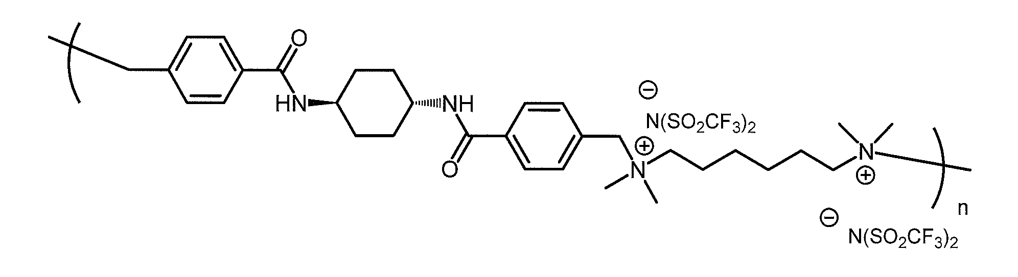
で表される化合物、すなわちポリ[(ジメチルイミノ)ヘキサン-1,6-ジイル(ジメチルイミノ)メチレン-1,4-フェニレンカルボニルイミノトランス-シクロヘキサン-1,4-ジイルイミノカルボニル-1,4-フェニレンメチレンビス(トリフルオロメタンスルホニル)アミド]を合成した。得られた化合物の重合度nは、重量平均分子量から換算した値が約62である。得られた化合物の同定は、以下のNMRスペクトルにより行った。
1H NMR(400MHz,DMSO-d6):δ 1.28-1.55(m,8H),1.75-1.98(m,8H),2.95(s,12H),3.22-3.37(m,4H),3.75-3.88(m,2H),4.56(s,4H),7.64(d, J=7.4Hz,4H),7.99(d,J=7.4Hz,4H),8.40(d,J=6.9Hz,2H)ppm
〔実施例8〕
(ゲル化剤(D)及びイオン液体の混合物の調製)
まず、洗浄済のガラス製のバイアル瓶(容量8mL)に、ゲル化剤(D)の合成例1で得られたイオン性ゲル化剤8mgを入れ、そこにメタノール150μLを滴下した。次に、バイアル瓶の蓋を閉め、バイアル瓶を80℃に設定されたホットプレート上で12分間加熱した。次に、バイアル瓶内に、イオン液体(C)としてのイオン液体#2(精製済みの1-ブチル-2,3-ジメチルイミダゾリウムビス(トリフルオロメチルスルホニル)イミド)400μLを加えた。その後すぐに、バイアル瓶の内容物を、ガラス製のパスツールピペット(イオン液体(C)の作製例1で使用したものと同じ)を用いて「吸い・吐き」を繰り返し行うことにより均一に混和させた後、バイアル瓶の蓋を閉め、超音波バスソニケーター(実施例1で使用したものと同じ)を用いて15分間超音波分散を行った。次に、バイアル瓶を80℃に設定されたホットプレート上で10分間加熱した。続いて、バイアル瓶から蓋を外し、バイアル瓶を真空乾燥オーブン(イオン液体(C)の作製例1で使用したものと同じ)に入れて90℃で2時間真空加熱した。バイアル瓶を80℃まで降温させてから真空乾燥オーブンから取り出し、バイアル瓶の蓋を閉め、暗所にて一晩保存し放冷した。これにより、ゲル化剤(D)及びイオン液体の混合物として、ゲル化剤の濃度が20g/Lであるイオン性ゲル化剤及び1-ブチル-2,3-ジメチルイミダゾリウムビス(トリフルオロメチルスルホニル)イミドの混合物(ゲル;以下、「ゲルストック1」と呼ぶ)を得た。
1H NMR(400MHz,DMSO-d6):δ 1.28-1.55(m,8H),1.75-1.98(m,8H),2.95(s,12H),3.22-3.37(m,4H),3.75-3.88(m,2H),4.56(s,4H),7.64(d, J=7.4Hz,4H),7.99(d,J=7.4Hz,4H),8.40(d,J=6.9Hz,2H)ppm
〔実施例8〕
(ゲル化剤(D)及びイオン液体の混合物の調製)
まず、洗浄済のガラス製のバイアル瓶(容量8mL)に、ゲル化剤(D)の合成例1で得られたイオン性ゲル化剤8mgを入れ、そこにメタノール150μLを滴下した。次に、バイアル瓶の蓋を閉め、バイアル瓶を80℃に設定されたホットプレート上で12分間加熱した。次に、バイアル瓶内に、イオン液体(C)としてのイオン液体#2(精製済みの1-ブチル-2,3-ジメチルイミダゾリウムビス(トリフルオロメチルスルホニル)イミド)400μLを加えた。その後すぐに、バイアル瓶の内容物を、ガラス製のパスツールピペット(イオン液体(C)の作製例1で使用したものと同じ)を用いて「吸い・吐き」を繰り返し行うことにより均一に混和させた後、バイアル瓶の蓋を閉め、超音波バスソニケーター(実施例1で使用したものと同じ)を用いて15分間超音波分散を行った。次に、バイアル瓶を80℃に設定されたホットプレート上で10分間加熱した。続いて、バイアル瓶から蓋を外し、バイアル瓶を真空乾燥オーブン(イオン液体(C)の作製例1で使用したものと同じ)に入れて90℃で2時間真空加熱した。バイアル瓶を80℃まで降温させてから真空乾燥オーブンから取り出し、バイアル瓶の蓋を閉め、暗所にて一晩保存し放冷した。これにより、ゲル化剤(D)及びイオン液体の混合物として、ゲル化剤の濃度が20g/Lであるイオン性ゲル化剤及び1-ブチル-2,3-ジメチルイミダゾリウムビス(トリフルオロメチルスルホニル)イミドの混合物(ゲル;以下、「ゲルストック1」と呼ぶ)を得た。
(有機光増感分子(A)及び有機発光分子(B)のイオン液体溶液の調製)
まず、洗浄済のガラス製のバイアル瓶(容量8mL)に、イオン液体(C)としての精製済みの1-ブチル-2,3-ジメチルイミダゾリウムビス(トリフルオロメチルスルホニル)イミド(製造元:IoLiTec Ionic Liquids Technologies GmbH)360μLに入れ、有機発光分子(B)としてのペリレンのトルエン溶液(濃度4×10⁻³M)250μLを加えた。
まず、洗浄済のガラス製のバイアル瓶(容量8mL)に、イオン液体(C)としての精製済みの1-ブチル-2,3-ジメチルイミダゾリウムビス(トリフルオロメチルスルホニル)イミド(製造元:IoLiTec Ionic Liquids Technologies GmbH)360μLに入れ、有機発光分子(B)としてのペリレンのトルエン溶液(濃度4×10⁻³M)250μLを加えた。
次に、バイアル瓶の内容物を、ガラス製のパスツールピペット(実施例1で使用したものと同じ)を用いて「吸い・吐き」を繰り返し行うことにより均一に混和させた後、バイアル瓶の蓋を閉め、超音波バスソニケーター(実施例1で使用したものと同じ)を用いて7分間超音波分散を行った。次に、このバイアル瓶から蓋を外し、その直後にこのバイアル瓶をグローブボックスのパスボックス内に入れ、パスボックス中でスクロールポンプ(実施例1で使用したものと同じ)を用いて1時間真空引きすることにより、トルエンを除去した。
さらに、バイアル瓶内に、有機発光分子(B)としてのペリレンのトルエン溶液(濃度4×10⁻³M)200μLと、有機光増感分子(A)としてのメソ-テトラフェニル-テトラベンゾポルフィリンパラジウムのトルエン溶液(濃度2×10⁻⁴M)50μLとを加えた。
次に、バイアル瓶の内容物を、ガラス製のパスツールピペット(イオン液体(C)の作製例1で使用したものと同じ)を用いて「吸い・吐き」を繰り返し行うことにより均一に混和させた後、バイアル瓶の蓋を閉め、超音波バスソニケーター(実施例1で使用したものと同じ)を用いて7分間超音波分散を行った。次に、このバイアル瓶から蓋を外し、その直後にこのバイアル瓶をグローブボックスのパスボックス内に入れ、パスボックス中でスクロールポンプ(実施例1で使用したものと同じ)を用いて2時間真空引きすることにより、トルエンを除去した。次に、バイアル瓶をグローブボックスのメインボックスに移動させた後、アルゴン雰囲気下でバイアル瓶の蓋を閉め、バイアル瓶をグローブボックスから取り出した。これにより、有機光増感分子(A)及び有機発光分子(B)のイオン液体溶液として、ペリレン及びメソ-テトラフェニル-テトラベンゾポルフィリンパラジウムの1-ブチル-2,3-ジメチルイミダゾリウムビス(トリフルオロメチルスルホニル)イミド溶液(以下、「試料溶液」と呼ぶ)を得た。
(混合及び封止)
ゲルストック1が入ったバイアル瓶(以下、「ゲルストックバイアル瓶」と呼ぶ)と、試料溶液が入ったバイアル瓶(以下、「試料バイアル瓶」と呼ぶ)とを、80~90℃に設定されたホットプレート上に置き、3~10分間予熱した。次に、試料バイアル瓶内の試料溶液に、ゲルストックバイアル瓶から分取したゲルストック1 40μLを加え、試料バイアル瓶の内容物を、ガラス製のパスツールピペット(イオン液体(C)の作製例1で使用したものと同じ)を用いて「吸い・吐き」を繰り返し行うことにより均一に混和させた。次に、蓋を外した状態の試料バイアル瓶を真空乾燥オーブン(イオン液体(C)の作製例1で使用したものと同じ)に入れて90℃で1時間真空加熱した後、真空乾燥オーブンから取り出した。
ゲルストック1が入ったバイアル瓶(以下、「ゲルストックバイアル瓶」と呼ぶ)と、試料溶液が入ったバイアル瓶(以下、「試料バイアル瓶」と呼ぶ)とを、80~90℃に設定されたホットプレート上に置き、3~10分間予熱した。次に、試料バイアル瓶内の試料溶液に、ゲルストックバイアル瓶から分取したゲルストック1 40μLを加え、試料バイアル瓶の内容物を、ガラス製のパスツールピペット(イオン液体(C)の作製例1で使用したものと同じ)を用いて「吸い・吐き」を繰り返し行うことにより均一に混和させた。次に、蓋を外した状態の試料バイアル瓶を真空乾燥オーブン(イオン液体(C)の作製例1で使用したものと同じ)に入れて90℃で1時間真空加熱した後、真空乾燥オーブンから取り出した。
次に、アルミニウム製のバイアルホルダーを120℃に設定されたホットプレート上で約30分間予熱した。予熱したバイアルホルダーをグローブボックスのパスボックス内に置き、その直後、真空乾燥オーブンから取り出した試料バイアル瓶をバイアルホルダーに設置し、パスボックス中でスクロールポンプ(実施例1で使用したものと同じ)を用いて5分間真空引きした。次に、アルゴン雰囲気下の(グローブボックスの)メインボックス内で試料バイアル瓶内の試料溶液の一部を注射針のついた注射器を用いて内寸2mm角の片端閉じ石英管に注入し、グローブボックス中に設置された真空チャンバー(実施例1で使用したものと同じ)内でターボ分子ポンプ(実施例1で使用したものと同じ)を用いて試料バイアル瓶及び石英管を25時間真空吸引した。その後、グローブボックスのメインボックス内で石英管の開口端をハンダで封止した。
これにより、本発明の一例に係る光波長変換要素を得た。この光波長変換要素が封入された石英管は、光波長変換要素が、その酸素濃度が十分抑制された状態で前記石英管中に封入されているものであり、形状を変えれば、光アップコンバージョンフィルターとして使用できる。
本実施例の光波長変換要素の体積は、その主成分であるイオン液体の体積(400μL)にほぼ等しく、本光波長変換要素中のゲル化剤の濃度(以下、「ゲル濃度」と呼ぶ)は約2g/Lであり、本光波長変換要素中のメソ-テトラフェニル-テトラベンゾポルフィリンパラジウムの濃度は約2.5×10-5Mであり、本光波長変換要素中のペリレンの濃度は約4.5×10-3Mである。
〔実施例9〕
(ゲル化剤(D)及びイオン液体の混合物の調製)
実施例8と同様にして、ゲル濃度が20g/Lであるゲルストック1を得た。
(ゲル化剤(D)及びイオン液体の混合物の調製)
実施例8と同様にして、ゲル濃度が20g/Lであるゲルストック1を得た。
(有機光増感分子(A)及び有機発光分子(B)のイオン液体溶液の調製)
イオン液体(C)としての精製済みの1-ブチル-2,3-ジメチルイミダゾリウムビス(トリフルオロメチルスルホニル)イミドの使用量を360μLから340μLに変更したこと以外は、実施例8と同様にして、試料溶液を得た。
イオン液体(C)としての精製済みの1-ブチル-2,3-ジメチルイミダゾリウムビス(トリフルオロメチルスルホニル)イミドの使用量を360μLから340μLに変更したこと以外は、実施例8と同様にして、試料溶液を得た。
(混合及び封止)
本実施例で得た試料溶液を使用し、ゲルストック1の使用量を40μLから60μLに変更したこと以外は、実施例8と同様にして、ゲル濃度が3g/Lである本発明の一例に係る光波長変換要素を得た。
本実施例で得た試料溶液を使用し、ゲルストック1の使用量を40μLから60μLに変更したこと以外は、実施例8と同様にして、ゲル濃度が3g/Lである本発明の一例に係る光波長変換要素を得た。
〔実施例10〕
(ゲル化剤(D)及びイオン液体の混合物の調製)
イオン性ゲル化剤の使用量を8mgから16mgに変更し、メタノール滴下後の加熱時間を12分間から15分間に変更したこと以外は、実施例8と同様にして、ゲル濃度が40g/Lであるイオン性ゲル化剤及び1-ブチル-2,3-ジメチルイミダゾリウムビス(トリフルオロメチルスルホニル)イミドの混合物(溶液;以下、「ゲルストック2」と呼ぶ)を得た。
(ゲル化剤(D)及びイオン液体の混合物の調製)
イオン性ゲル化剤の使用量を8mgから16mgに変更し、メタノール滴下後の加熱時間を12分間から15分間に変更したこと以外は、実施例8と同様にして、ゲル濃度が40g/Lであるイオン性ゲル化剤及び1-ブチル-2,3-ジメチルイミダゾリウムビス(トリフルオロメチルスルホニル)イミドの混合物(溶液;以下、「ゲルストック2」と呼ぶ)を得た。
(有機光増感分子(A)及び有機発光分子(B)のイオン液体溶液の調製)
イオン液体(C)としての精製済みの1-ブチル-2,3-ジメチルイミダゾリウムビス(トリフルオロメチルスルホニル)イミドの使用量を360μLから350μLに変更したこと以外は、実施例8と同様にして、試料溶液を得た。
イオン液体(C)としての精製済みの1-ブチル-2,3-ジメチルイミダゾリウムビス(トリフルオロメチルスルホニル)イミドの使用量を360μLから350μLに変更したこと以外は、実施例8と同様にして、試料溶液を得た。
(混合及び封止)
本実施例で得た試料溶液を使用し、ゲルストック1 40μLに代えてゲルストック2 50μLを用いたこと以外は、実施例8と同様にして、ゲル濃度が5g/Lである本発明の一例に係る光波長変換要素を得た。
本実施例で得た試料溶液を使用し、ゲルストック1 40μLに代えてゲルストック2 50μLを用いたこと以外は、実施例8と同様にして、ゲル濃度が5g/Lである本発明の一例に係る光波長変換要素を得た。
〔実施例11〕
(ゲル化剤(D)及びイオン液体の混合物の調製)
実施例10と同様にして、ゲル濃度が40g/Lであるゲルストック2を得た。
(ゲル化剤(D)及びイオン液体の混合物の調製)
実施例10と同様にして、ゲル濃度が40g/Lであるゲルストック2を得た。
(有機光増感分子(A)及び有機発光分子(B)のイオン液体溶液の調製)
イオン液体(C)としての精製済みの1-ブチル-2,3-ジメチルイミダゾリウムビス(トリフルオロメチルスルホニル)イミドの使用量を360μLから330μLに変更したこと以外は、実施例8と同様にして、試料溶液を得た。
イオン液体(C)としての精製済みの1-ブチル-2,3-ジメチルイミダゾリウムビス(トリフルオロメチルスルホニル)イミドの使用量を360μLから330μLに変更したこと以外は、実施例8と同様にして、試料溶液を得た。
(混合及び封止)
本実施例で得た試料溶液を使用し、ゲルストック1 40μLに代えてゲルストック2 70μLを用いたこと以外は、実施例8と同様にして、ゲル濃度が7g/Lである本発明の一例に係る光波長変換要素を得た。
本実施例で得た試料溶液を使用し、ゲルストック1 40μLに代えてゲルストック2 70μLを用いたこと以外は、実施例8と同様にして、ゲル濃度が7g/Lである本発明の一例に係る光波長変換要素を得た。
〔実施例12〕
(ゲル化剤(D)及びイオン液体の混合物の調製)
実施例10と同様にして、ゲル濃度が40g/Lであるゲルストック2を得た。
(ゲル化剤(D)及びイオン液体の混合物の調製)
実施例10と同様にして、ゲル濃度が40g/Lであるゲルストック2を得た。
(有機光増感分子(A)及び有機発光分子(B)のイオン液体溶液の調製)
イオン液体(C)としての精製済みの1-ブチル-2,3-ジメチルイミダゾリウムビス(トリフルオロメチルスルホニル)イミドの使用量を360μLから300μLに変更したこと以外は、実施例8と同様にして、試料溶液を得た。
イオン液体(C)としての精製済みの1-ブチル-2,3-ジメチルイミダゾリウムビス(トリフルオロメチルスルホニル)イミドの使用量を360μLから300μLに変更したこと以外は、実施例8と同様にして、試料溶液を得た。
(混合及び封止)
本実施例で得た試料溶液を使用し、ゲルストック1 40μLに代えてゲルストック2 100μLを用いたこと以外は、実施例8と同様にして、ゲル濃度が10g/Lである本発明の一例に係る光波長変換要素を得た。
本実施例で得た試料溶液を使用し、ゲルストック1 40μLに代えてゲルストック2 100μLを用いたこと以外は、実施例8と同様にして、ゲル濃度が10g/Lである本発明の一例に係る光波長変換要素を得た。
〔実施例13〕
(ゲル化剤(D)及びイオン液体の混合物の調製)
イオン性ゲル化剤の使用量を8mgから48mgに変更し、メタノール滴下直後の加熱時間を12分間から20分間に変更したこと以外は、実施例8と同様にして、ゲル濃度が120g/Lであるイオン性ゲル化剤及び1-ブチル-2,3-ジメチルイミダゾリウムビス(トリフルオロメチルスルホニル)イミドの混合物(溶液;以下、「ゲルストック3」と呼ぶ)を得た。
(ゲル化剤(D)及びイオン液体の混合物の調製)
イオン性ゲル化剤の使用量を8mgから48mgに変更し、メタノール滴下直後の加熱時間を12分間から20分間に変更したこと以外は、実施例8と同様にして、ゲル濃度が120g/Lであるイオン性ゲル化剤及び1-ブチル-2,3-ジメチルイミダゾリウムビス(トリフルオロメチルスルホニル)イミドの混合物(溶液;以下、「ゲルストック3」と呼ぶ)を得た。
(有機光増感分子(A)及び有機発光分子(B)のイオン液体溶液の調製)
イオン液体(C)としての精製済みの1-ブチル-2,3-ジメチルイミダゾリウムビス(トリフルオロメチルスルホニル)イミドの使用量を360μLから350μLに変更したこと以外は、実施例8と同様にして、試料溶液を得た。
イオン液体(C)としての精製済みの1-ブチル-2,3-ジメチルイミダゾリウムビス(トリフルオロメチルスルホニル)イミドの使用量を360μLから350μLに変更したこと以外は、実施例8と同様にして、試料溶液を得た。
(混合及び封止)
本実施例で得た試料溶液を使用し、ゲルストック1 40μLに代えてゲルストック3 50μLを用いたこと以外は、実施例8と同様にして、ゲル濃度が15g/Lである本発明の一例に係る光波長変換要素を得た。
本実施例で得た試料溶液を使用し、ゲルストック1 40μLに代えてゲルストック3 50μLを用いたこと以外は、実施例8と同様にして、ゲル濃度が15g/Lである本発明の一例に係る光波長変換要素を得た。
〔実施例14〕
(ゲル化剤(D)及びイオン液体の混合物の調製)
実施例8と同様にして、ゲル濃度が120g/Lであるゲルストック3を得た。
(ゲル化剤(D)及びイオン液体の混合物の調製)
実施例8と同様にして、ゲル濃度が120g/Lであるゲルストック3を得た。
(有機光増感分子(A)及び有機発光分子(B)のイオン液体溶液の調製)
イオン液体(C)としての精製済みの1-ブチル-2,3-ジメチルイミダゾリウムビス(トリフルオロメチルスルホニル)イミドの使用量を360μLから323μLに変更したこと以外は、実施例8と同様にして、試料溶液を得た。
イオン液体(C)としての精製済みの1-ブチル-2,3-ジメチルイミダゾリウムビス(トリフルオロメチルスルホニル)イミドの使用量を360μLから323μLに変更したこと以外は、実施例8と同様にして、試料溶液を得た。
(混合及び封止)
本実施例で得た試料溶液を使用し、ゲルストック1 40μLに代えてゲルストック3 77μLを用いたこと以外は、実施例8と同様にして、ゲル濃度が23g/Lである本発明の一例に係る光波長変換要素を得た。
本実施例で得た試料溶液を使用し、ゲルストック1 40μLに代えてゲルストック3 77μLを用いたこと以外は、実施例8と同様にして、ゲル濃度が23g/Lである本発明の一例に係る光波長変換要素を得た。
〔光波長変換要素の目視観察〕
実施例8~14で得られた光波長変換要素をガラス製のバイアル瓶(実施例1で使用したものと同じ)中に入れ、時間経過に伴う様子の変化を目視観察した結果を下記表1にまとめて示す。下記表1の結果より、光波長変換要素は、ゲル濃度が3g/L以上である場合に、2日間経過後においてゲル状態であることが確認された。
実施例8~14で得られた光波長変換要素をガラス製のバイアル瓶(実施例1で使用したものと同じ)中に入れ、時間経過に伴う様子の変化を目視観察した結果を下記表1にまとめて示す。下記表1の結果より、光波長変換要素は、ゲル濃度が3g/L以上である場合に、2日間経過後においてゲル状態であることが確認された。

〔光波長変換要素のアップコンバージョン発光スペクトル及びアップコンバージョン発光強度〕
実施例8~14で得られた光波長変換要素が封入された石英管を専用の試料ホルダーに固定し、その石英管に対し、励起光として連続光レーザー発光器(製造元:CVI Melles Griot Inc.、型番:25LHP928-249)から出射させた連続光レーザー発光(波長(励起波長):632.8nm、スポット径:約0.8mm、出力パワー(励起強度):20mWを照射したこと以外は、実施例1と同じ手順で、アップコンバージョン発光のスペクトル(スペクトル形状)および強度を測定した。
実施例8~14で得られた光波長変換要素が封入された石英管を専用の試料ホルダーに固定し、その石英管に対し、励起光として連続光レーザー発光器(製造元:CVI Melles Griot Inc.、型番:25LHP928-249)から出射させた連続光レーザー発光(波長(励起波長):632.8nm、スポット径:約0.8mm、出力パワー(励起強度):20mWを照射したこと以外は、実施例1と同じ手順で、アップコンバージョン発光のスペクトル(スペクトル形状)および強度を測定した。
測定されたアップコンバージョン発光スペクトルを図20に示し、測定されたアップコンバージョンの発光強度(積分値)及びピーク発光強度(相対値)を下記表2に示す。
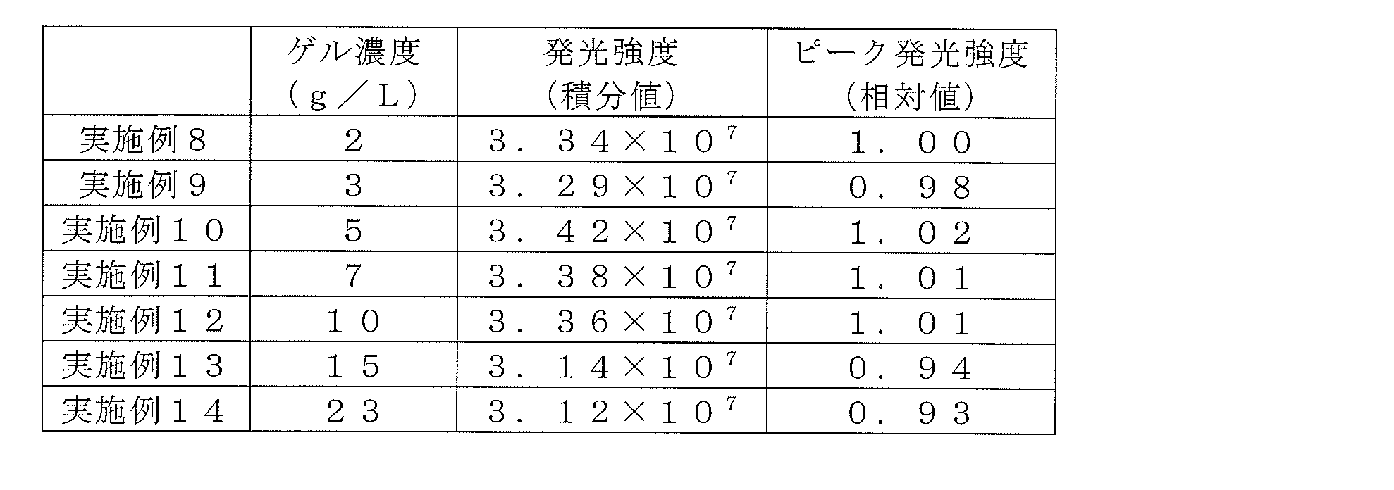
また、実施例8~14で得られた光波長変換要素について、ゲル濃度の変化に対する、アップコンバージョン発光強度(ピーク発光強度)(相対値)の変化を図21に示す。
これら図20・21及び表2に示す結果から、本発明の光波長変換要素のアップコンバージョン発光強度にはゲル濃度依存性がなく、本発明の光波長変換要素が、ゲル濃度にかかわらず十分なアップコンバージョン発光強度を示すことが分かった。
1 太陽電池層
2 透明背面電極
3 透明絶縁膜
4 アップコンバージョン層
5 光反射膜
7 受光面電極
8 ガラスチャネル
9 ガス
10 光触媒が添加された水
11 機械的支持体
本発明は、その精神又は主要な特徴から逸脱することなく、他のいろいろな形で実施することができる。そのため、上述の実施例はあらゆる点で単なる例示にすぎず、限定的に解釈してはならない。本発明の範囲は特許請求の範囲によって示すものであって、明細書本文には、なんら拘束されない。さらに、特許請求の範囲の均等範囲に属する変形や変更は、全て本発明の範囲内のものである。
2 透明背面電極
3 透明絶縁膜
4 アップコンバージョン層
5 光反射膜
7 受光面電極
8 ガラスチャネル
9 ガス
10 光触媒が添加された水
11 機械的支持体
本発明は、その精神又は主要な特徴から逸脱することなく、他のいろいろな形で実施することができる。そのため、上述の実施例はあらゆる点で単なる例示にすぎず、限定的に解釈してはならない。本発明の範囲は特許請求の範囲によって示すものであって、明細書本文には、なんら拘束されない。さらに、特許請求の範囲の均等範囲に属する変形や変更は、全て本発明の範囲内のものである。
また、この出願は、2013年12月13日に日本で出願された特願2013-258670、及び2014年1月31日に日本で出願された特願2014-017103に基づく優先権を請求する。これに言及することにより、その全ての内容は本出願に組み込まれるものである。
Claims (14)
- 三重項-三重項消滅過程を示す組み合わせである有機光増感分子(A)および有機発光分子(B)を、イオン液体(C)中に溶解および/または分散させてなる、目視上均質かつ透明な光波長変換要素であって、
前記イオン液体(C)が、前記イオン液体(C)をその9倍の体積の超純水で洗浄したときに、洗浄後の水のpHが5より大きくなるものであることを特徴とする光波長変換要素。 - 前記有機光増感分子(A)の吸収極大波長が、500~700nmの範囲内にあることを特徴とする請求項1に記載の光波長変換要素。
- 前記有機光増感分子(A)が、その構造中に金属を含まないことを特徴とする請求項1または2に記載の光波長変換要素。
- 前記有機光増感分子(A)が、下記一般式(1)

で表される化合物であることを特徴とする請求項1~3のいずれか一項に記載の光波長変換要素。 - 前記一般式(1)中のR1~R5がそれぞれ独立に、水素原子、ハロゲン原子、置換基を有してもよい炭素数1~4の脂肪族炭化水素基、置換基を有してもよいフェニル基、置換基を有してもよいフェノキシ基、置換基を有してもよいチエニル基、置換基を有してもよいチエノキシ基、下記式(2)

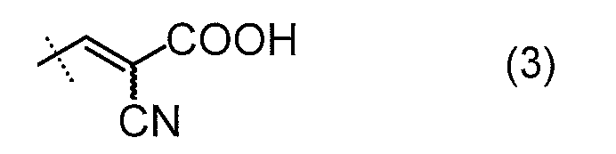
- 前記有機光増感分子(A)が、下記一般式(4)

で表される化合物であることを特徴とする請求項1~5のいずれか一項に記載の光波長変換要素。 - ゲル化剤(D)をさらに含むことを特徴とする請求項1~6のいずれか一項に記載の光波長変換要素。
- ゲル状態となっていることを特徴とする請求項7に記載の光波長変換要素。
- 前記ゲル化剤(D)は、イオン性ゲル化剤であることを特徴とする請求項7又は8に記載の光波長変換要素。
- 前記ゲル化剤(D)は、非イオン性重合体であることを特徴とする請求項7又は8に記載の光波長変換要素。
- 請求項1~10のいずれか一項に記載の光波長変換要素を用いた太陽電池。
- 請求項1~10のいずれか一項に記載の光波長変換要素を用いた光触媒。
- 請求項1~10のいずれか一項に記載の光波長変換要素を用いた光触媒型水素・酸素発生装置。
- 光をより短い波長の光に変換する光アップコンバージョンフィルターであって、
請求項1~10のいずれか一項に記載の光波長変換要素と、
セルとを備え、
前記光波長変換要素が、前記セル中に封入されていることを特徴とする光アップコンバージョンフィルター。
Priority Applications (2)
| Application Number | Priority Date | Filing Date | Title |
|---|---|---|---|
| US15/102,748 US20160312113A1 (en) | 2013-12-13 | 2014-11-21 | Optical Wavelength Conversion Element Containing Ionic Liquid, And Article Equipped With Said Optical Wavelength Conversion Element |
| CN201480068367.5A CN105874033A (zh) | 2013-12-13 | 2014-11-21 | 含有离子液体的光波长转换元件及包含该光波长转换元件的物品 |
Applications Claiming Priority (4)
| Application Number | Priority Date | Filing Date | Title |
|---|---|---|---|
| JP2013258670 | 2013-12-13 | ||
| JP2013-258670 | 2013-12-13 | ||
| JP2014017103 | 2014-01-31 | ||
| JP2014-017103 | 2014-01-31 |
Publications (1)
| Publication Number | Publication Date |
|---|---|
| WO2015087690A1 true WO2015087690A1 (ja) | 2015-06-18 |
Family
ID=53371004
Family Applications (1)
| Application Number | Title | Priority Date | Filing Date |
|---|---|---|---|
| PCT/JP2014/080937 Ceased WO2015087690A1 (ja) | 2013-12-13 | 2014-11-21 | イオン液体を含む光波長変換要素およびその光波長変換要素を含む物品 |
Country Status (3)
| Country | Link |
|---|---|
| US (1) | US20160312113A1 (ja) |
| CN (1) | CN105874033A (ja) |
| WO (1) | WO2015087690A1 (ja) |
Cited By (5)
| Publication number | Priority date | Publication date | Assignee | Title |
|---|---|---|---|---|
| CN105238092A (zh) * | 2015-10-30 | 2016-01-13 | 东莞理工学院 | 一种新型2,6-位取代的bodipy类有机染料敏化剂及其制备方法 |
| JP2017037299A (ja) * | 2015-08-11 | 2017-02-16 | Jsr株式会社 | 着色組成物、着色硬化膜及び表示素子 |
| JP2017082063A (ja) * | 2015-10-26 | 2017-05-18 | 日本化薬株式会社 | 深共晶溶媒を含む光波長変換要素およびその光波長変換要素を含む物品 |
| JP2018180277A (ja) * | 2017-04-13 | 2018-11-15 | 国立大学法人東京工業大学 | 深共晶溶媒を含む光波長変換要素およびその光波長変換要素を含む物品 |
| CN115678384A (zh) * | 2022-11-12 | 2023-02-03 | 贾雯 | 一种水性树脂涂料组合物及其制备方法 |
Families Citing this family (10)
| Publication number | Priority date | Publication date | Assignee | Title |
|---|---|---|---|---|
| WO2015115556A1 (ja) | 2014-01-31 | 2015-08-06 | 日本化薬株式会社 | イオン液体を含む光波長変換要素およびその光波長変換要素を含む物品 |
| CN109563405B (zh) | 2016-07-29 | 2022-06-17 | 株式会社Lg化学 | 含氮环状化合物、包含其的色彩转换膜以及包含其的背光单元和显示装置 |
| KR102217705B1 (ko) | 2016-12-19 | 2021-02-18 | 후지필름 가부시키가이샤 | 파장 변환용 발광성 수지 조성물 및 그 제조 방법과, 파장 변환 부재 및 발광 소자 |
| CN107064031B (zh) * | 2017-03-27 | 2020-04-24 | 中国科学院化学研究所 | 一种离子液体体系中分子分布的调控方法及应用 |
| CN107403696A (zh) * | 2017-07-14 | 2017-11-28 | 中国科学院化学研究所 | 聚合物修饰类囊体工作电极及其制备方法、三电极体系及其应用 |
| CN107783319B (zh) * | 2017-11-21 | 2024-02-09 | 北京空间机电研究所 | 一种实现光谱透过率连续选择性调控的智能玻璃仪器 |
| JP2022508240A (ja) | 2018-11-27 | 2022-01-19 | プレジデント アンド フェローズ オブ ハーバード カレッジ | 3dプリント及び他の用途のための光子アップコンバージョンナノカプセル |
| WO2020257231A1 (en) * | 2019-06-21 | 2020-12-24 | President And Fellows Of Harvard College | Triplet exciton acceptors for increasing upconversion thresholds for 3d printing |
| CN111732950B (zh) * | 2020-07-28 | 2020-11-10 | 苏州科技大学 | 氮杂蒽衍生物tta-uc弱光上转换体系及其制备方法与应用 |
| CN113769784B (zh) * | 2021-10-11 | 2024-02-20 | 山东能源集团有限公司 | 一种木质素模型化合物降解的方法和上转换催化剂 |
Citations (3)
| Publication number | Priority date | Publication date | Assignee | Title |
|---|---|---|---|---|
| JP2011505479A (ja) * | 2007-12-04 | 2011-02-24 | ソニー株式会社 | 光子のエネルギーをアップコンバージョンさせるための媒体 |
| WO2012050137A1 (ja) * | 2010-10-13 | 2012-04-19 | 国立大学法人東京工業大学 | イオン液体を含む光変換要素およびその製造方法ならびに光変換要素を含む装置 |
| JP2013168424A (ja) * | 2012-02-14 | 2013-08-29 | Idemitsu Kosan Co Ltd | 有機薄膜太陽電池素子用材料、及びそれを用いた有機薄膜太陽電池 |
-
2014
- 2014-11-21 CN CN201480068367.5A patent/CN105874033A/zh active Pending
- 2014-11-21 US US15/102,748 patent/US20160312113A1/en not_active Abandoned
- 2014-11-21 WO PCT/JP2014/080937 patent/WO2015087690A1/ja not_active Ceased
Patent Citations (3)
| Publication number | Priority date | Publication date | Assignee | Title |
|---|---|---|---|---|
| JP2011505479A (ja) * | 2007-12-04 | 2011-02-24 | ソニー株式会社 | 光子のエネルギーをアップコンバージョンさせるための媒体 |
| WO2012050137A1 (ja) * | 2010-10-13 | 2012-04-19 | 国立大学法人東京工業大学 | イオン液体を含む光変換要素およびその製造方法ならびに光変換要素を含む装置 |
| JP2013168424A (ja) * | 2012-02-14 | 2013-08-29 | Idemitsu Kosan Co Ltd | 有機薄膜太陽電池素子用材料、及びそれを用いた有機薄膜太陽電池 |
Non-Patent Citations (5)
| Title |
|---|
| MAO MAO ET AL.: "New 2,6-modified BODIPY sensitizers for dye-sensitized solar cells", DYES AND PIGMENTS, vol. 94, 2012, pages 224 - 232 * |
| YOICHI MURAKAMI ET AL.: "Hikari Upconverter no Dynamics Ion Ekitaichu deno Energy · Bunshi Yuso", DAI 49 KAI NATIONAL HEAT TRANSFER SYMPOSIUM OF JAPAN KOEN RONBUNSHU, May 2012 (2012-05-01) * |
| YOICHI MURAKAMI ET AL.: "Photochemical photon upconverters with ionic liquids", CHEMICAL PHYSICS LETTERS, vol. 516, 2011, pages 56 - 61 * |
| YOICHI MURAKAMI: "Development of Phase-Stable Photon Upconverters for Efficient Solar Energy Utilization", THERMAL SCIENCE & ENGINEERING, vol. 20, no. 2, 2012, pages 15 - 26 * |
| YOICHI MURAKAMI: "Kokoritsu na Hikari Upconverter no Kaihatsu to sono Mechanism Kaimei", DAI 48 KAI NATIONAL HEAT TRANSFER SYMPOSIUM OF JAPAN KOEN RONBUNSHU, June 2011 (2011-06-01) * |
Cited By (6)
| Publication number | Priority date | Publication date | Assignee | Title |
|---|---|---|---|---|
| JP2017037299A (ja) * | 2015-08-11 | 2017-02-16 | Jsr株式会社 | 着色組成物、着色硬化膜及び表示素子 |
| JP2017082063A (ja) * | 2015-10-26 | 2017-05-18 | 日本化薬株式会社 | 深共晶溶媒を含む光波長変換要素およびその光波長変換要素を含む物品 |
| CN105238092A (zh) * | 2015-10-30 | 2016-01-13 | 东莞理工学院 | 一种新型2,6-位取代的bodipy类有机染料敏化剂及其制备方法 |
| JP2018180277A (ja) * | 2017-04-13 | 2018-11-15 | 国立大学法人東京工業大学 | 深共晶溶媒を含む光波長変換要素およびその光波長変換要素を含む物品 |
| CN115678384A (zh) * | 2022-11-12 | 2023-02-03 | 贾雯 | 一种水性树脂涂料组合物及其制备方法 |
| CN115678384B (zh) * | 2022-11-12 | 2023-10-31 | 中山市海恒包装材料有限公司 | 一种水性树脂涂料组合物及其制备方法 |
Also Published As
| Publication number | Publication date |
|---|---|
| CN105874033A (zh) | 2016-08-17 |
| US20160312113A1 (en) | 2016-10-27 |
Similar Documents
| Publication | Publication Date | Title |
|---|---|---|
| WO2015087690A1 (ja) | イオン液体を含む光波長変換要素およびその光波長変換要素を含む物品 | |
| JP6436356B2 (ja) | イオン液体を含む光波長変換要素およびその光波長変換要素を含む物品 | |
| EP2628777B1 (en) | Light conversion element containing ion liquid, production method of same, and device containing photovoltaic conversion element | |
| Fallon et al. | Molecular engineering of chromophores to enable triplet–triplet annihilation upconversion | |
| De Bastiani et al. | Inside perovskites: quantum luminescence from bulk Cs4PbBr6 single crystals | |
| JP2015163676A (ja) | イオン液体を含む光波長変換要素およびその光波長変換要素を含む物品 | |
| Nagarajan et al. | Access to triplet excited state in core-twisted perylenediimide | |
| EP2075304A1 (en) | A device for modifying the wavelenght range of a spectrum of light | |
| CN105694848B (zh) | 一种基于水凝胶的固态上转换发光材料及其制备方法 | |
| Raišys et al. | Triplet exciton diffusion and quenching in matrix-free solid photon upconversion films | |
| JP7054090B2 (ja) | 光波長変換要素およびその光波長変換要素を含む物品 | |
| JP2018194684A (ja) | 光アップコンバージョンフィルムおよび光アップコンバージョンフィルムを用いた物品 | |
| Liang et al. | New Anthracene Derivatives as Triplet Acceptors for Efficient Green‐to‐Blue Low‐Power Upconversion | |
| JP7214710B2 (ja) | 少なくとも1つのタイプのゲスト分子を受容しているゼオライトl材料の調製方法 | |
| Guo et al. | The synthesis, molecular structure and photophysical properties of 2, 9, 16, 23-tetrakis (7-coumarinoxy-4-methyl)-phthalocyanine sensitizer | |
| Mori et al. | Solid State Photon Up-Conversion Emission from Chromophore-Tethered PPV Films | |
| Mao et al. | Stabilizing the Quinoidal Form of Polycyclic Aromatic Hydrocarbons by O─ B← N Units to Give a> 1000 nm Redshift in the Absorption Wavelength | |
| Shang et al. | Realizing Excellent Nonlinear Optical Performance in Near‐Infrared Region of Helicene‐Functionalized Arenes | |
| Bolle et al. | Tailoring the solid-state fluorescence of BODIPY by supramolecular assembly with polyoxometalates | |
| JP6692014B2 (ja) | イオン液体を含む光波長変換要素およびその光波長変換要素を含む物品 | |
| Chen et al. | Investigation on Charge Carrier Recombination of Hybrid Organic–Inorganic Perovskites Doped with Aggregation‐Induced Emission Luminogen under High Photon Flux Excitation | |
| CN103013498A (zh) | 2,7-二(三苯胺基)螺二芴的应用 | |
| Portillo-Moreno et al. | Morphological, structural and optical analysis of green, red and yellow emission bands in new chiral imines with a benzothiophene moiety | |
| Liu et al. | Reengineering of crown ether end-activated donor–acceptor–donor non-equivalent structured copolymers for photocatalytic hydrogen generation | |
| JP2017082063A (ja) | 深共晶溶媒を含む光波長変換要素およびその光波長変換要素を含む物品 |
Legal Events
| Date | Code | Title | Description |
|---|---|---|---|
| 121 | Ep: the epo has been informed by wipo that ep was designated in this application |
Ref document number: 14869836 Country of ref document: EP Kind code of ref document: A1 |
|
| WWE | Wipo information: entry into national phase |
Ref document number: 15102748 Country of ref document: US |
|
| NENP | Non-entry into the national phase |
Ref country code: DE |
|
| 122 | Ep: pct application non-entry in european phase |
Ref document number: 14869836 Country of ref document: EP Kind code of ref document: A1 |