WO2015087552A1 - プレートフィン熱交換器型凝縮器、及び、凝縮システム - Google Patents
プレートフィン熱交換器型凝縮器、及び、凝縮システム Download PDFInfo
- Publication number
- WO2015087552A1 WO2015087552A1 PCT/JP2014/006189 JP2014006189W WO2015087552A1 WO 2015087552 A1 WO2015087552 A1 WO 2015087552A1 JP 2014006189 W JP2014006189 W JP 2014006189W WO 2015087552 A1 WO2015087552 A1 WO 2015087552A1
- Authority
- WO
- WIPO (PCT)
- Prior art keywords
- gas
- flow path
- condensed
- condenser
- heat exchanger
- Prior art date
- Legal status (The legal status is an assumption and is not a legal conclusion. Google has not performed a legal analysis and makes no representation as to the accuracy of the status listed.)
- Ceased
Links
Images



Classifications
-
- F—MECHANICAL ENGINEERING; LIGHTING; HEATING; WEAPONS; BLASTING
- F28—HEAT EXCHANGE IN GENERAL
- F28D—HEAT-EXCHANGE APPARATUS, NOT PROVIDED FOR IN ANOTHER SUBCLASS, IN WHICH THE HEAT-EXCHANGE MEDIA DO NOT COME INTO DIRECT CONTACT
- F28D9/00—Heat-exchange apparatus having stationary plate-like or laminated conduit assemblies for both heat-exchange media, the media being in contact with different sides of a conduit wall
- F28D9/0062—Heat-exchange apparatus having stationary plate-like or laminated conduit assemblies for both heat-exchange media, the media being in contact with different sides of a conduit wall the conduits for one heat-exchange medium being formed by spaced plates with inserted elements
-
- B—PERFORMING OPERATIONS; TRANSPORTING
- B01—PHYSICAL OR CHEMICAL PROCESSES OR APPARATUS IN GENERAL
- B01D—SEPARATION
- B01D5/00—Condensation of vapours; Recovering volatile solvents by condensation
- B01D5/0003—Condensation of vapours; Recovering volatile solvents by condensation by using heat-exchange surfaces for indirect contact between gases or vapours and the cooling medium
- B01D5/0015—Plates
-
- F—MECHANICAL ENGINEERING; LIGHTING; HEATING; WEAPONS; BLASTING
- F25—REFRIGERATION OR COOLING; COMBINED HEATING AND REFRIGERATION SYSTEMS; HEAT PUMP SYSTEMS; MANUFACTURE OR STORAGE OF ICE; LIQUEFACTION SOLIDIFICATION OF GASES
- F25J—LIQUEFACTION, SOLIDIFICATION OR SEPARATION OF GASES OR GASEOUS OR LIQUEFIED GASEOUS MIXTURES BY PRESSURE AND COLD TREATMENT OR BY BRINGING THEM INTO THE SUPERCRITICAL STATE
- F25J5/00—Arrangements of cold exchangers or cold accumulators in separation or liquefaction plants
- F25J5/002—Arrangements of cold exchangers or cold accumulators in separation or liquefaction plants for continuously recuperating cold, i.e. in a so-called recuperative heat exchanger
- F25J5/005—Arrangements of cold exchangers or cold accumulators in separation or liquefaction plants for continuously recuperating cold, i.e. in a so-called recuperative heat exchanger in a reboiler-condenser, e.g. within a column
-
- F—MECHANICAL ENGINEERING; LIGHTING; HEATING; WEAPONS; BLASTING
- F28—HEAT EXCHANGE IN GENERAL
- F28D—HEAT-EXCHANGE APPARATUS, NOT PROVIDED FOR IN ANOTHER SUBCLASS, IN WHICH THE HEAT-EXCHANGE MEDIA DO NOT COME INTO DIRECT CONTACT
- F28D9/00—Heat-exchange apparatus having stationary plate-like or laminated conduit assemblies for both heat-exchange media, the media being in contact with different sides of a conduit wall
- F28D9/0062—Heat-exchange apparatus having stationary plate-like or laminated conduit assemblies for both heat-exchange media, the media being in contact with different sides of a conduit wall the conduits for one heat-exchange medium being formed by spaced plates with inserted elements
- F28D9/0068—Heat-exchange apparatus having stationary plate-like or laminated conduit assemblies for both heat-exchange media, the media being in contact with different sides of a conduit wall the conduits for one heat-exchange medium being formed by spaced plates with inserted elements with means for changing flow direction of one heat exchange medium, e.g. using deflecting zones
-
- F—MECHANICAL ENGINEERING; LIGHTING; HEATING; WEAPONS; BLASTING
- F28—HEAT EXCHANGE IN GENERAL
- F28F—DETAILS OF HEAT-EXCHANGE AND HEAT-TRANSFER APPARATUS, OF GENERAL APPLICATION
- F28F3/00—Plate-like or laminated elements; Assemblies of plate-like or laminated elements
- F28F3/02—Elements or assemblies thereof with means for increasing heat-transfer area, e.g. with fins, with recesses, with corrugations
- F28F3/025—Elements or assemblies thereof with means for increasing heat-transfer area, e.g. with fins, with recesses, with corrugations the means being corrugated, plate-like elements
- F28F3/027—Elements or assemblies thereof with means for increasing heat-transfer area, e.g. with fins, with recesses, with corrugations the means being corrugated, plate-like elements with openings, e.g. louvered corrugated fins; Assemblies of corrugated strips
-
- F—MECHANICAL ENGINEERING; LIGHTING; HEATING; WEAPONS; BLASTING
- F25—REFRIGERATION OR COOLING; COMBINED HEATING AND REFRIGERATION SYSTEMS; HEAT PUMP SYSTEMS; MANUFACTURE OR STORAGE OF ICE; LIQUEFACTION SOLIDIFICATION OF GASES
- F25J—LIQUEFACTION, SOLIDIFICATION OR SEPARATION OF GASES OR GASEOUS OR LIQUEFIED GASEOUS MIXTURES BY PRESSURE AND COLD TREATMENT OR BY BRINGING THEM INTO THE SUPERCRITICAL STATE
- F25J2290/00—Other details not covered by groups F25J2200/00 - F25J2280/00
- F25J2290/32—Details on header or distribution passages of heat exchangers, e.g. of reboiler-condenser or plate heat exchangers
-
- F—MECHANICAL ENGINEERING; LIGHTING; HEATING; WEAPONS; BLASTING
- F28—HEAT EXCHANGE IN GENERAL
- F28B—STEAM OR VAPOUR CONDENSERS
- F28B9/00—Auxiliary systems, arrangements, or devices
- F28B9/10—Auxiliary systems, arrangements, or devices for extracting, cooling, and removing non-condensable gases
-
- F—MECHANICAL ENGINEERING; LIGHTING; HEATING; WEAPONS; BLASTING
- F28—HEAT EXCHANGE IN GENERAL
- F28D—HEAT-EXCHANGE APPARATUS, NOT PROVIDED FOR IN ANOTHER SUBCLASS, IN WHICH THE HEAT-EXCHANGE MEDIA DO NOT COME INTO DIRECT CONTACT
- F28D21/00—Heat-exchange apparatus not covered by any of the groups F28D1/00 - F28D20/00
- F28D2021/0019—Other heat exchangers for particular applications; Heat exchange systems not otherwise provided for
- F28D2021/0033—Other heat exchangers for particular applications; Heat exchange systems not otherwise provided for for cryogenic applications
-
- F—MECHANICAL ENGINEERING; LIGHTING; HEATING; WEAPONS; BLASTING
- F28—HEAT EXCHANGE IN GENERAL
- F28D—HEAT-EXCHANGE APPARATUS, NOT PROVIDED FOR IN ANOTHER SUBCLASS, IN WHICH THE HEAT-EXCHANGE MEDIA DO NOT COME INTO DIRECT CONTACT
- F28D21/00—Heat-exchange apparatus not covered by any of the groups F28D1/00 - F28D20/00
- F28D2021/0019—Other heat exchangers for particular applications; Heat exchange systems not otherwise provided for
- F28D2021/0061—Other heat exchangers for particular applications; Heat exchange systems not otherwise provided for for phase-change applications
- F28D2021/0063—Condensers
-
- F—MECHANICAL ENGINEERING; LIGHTING; HEATING; WEAPONS; BLASTING
- F28—HEAT EXCHANGE IN GENERAL
- F28F—DETAILS OF HEAT-EXCHANGE AND HEAT-TRANSFER APPARATUS, OF GENERAL APPLICATION
- F28F2265/00—Safety or protection arrangements; Arrangements for preventing malfunction
- F28F2265/18—Safety or protection arrangements; Arrangements for preventing malfunction for removing contaminants, e.g. for degassing
Definitions
- the technology disclosed herein relates to a plate fin heat exchanger type condenser and a condensing system including the condenser.
- Patent Document 1 describes a condenser configured to supply a gas to be condensed directly into a container in which a cooling fluid is stored.
- this condenser has a non-condensable gas discharge valve attached to the container in order to condense the gas to be condensed including non-condensable gas, and the non-condensable gas is discharged out of the container through the discharge valve.
- Patent Document 1 a gas-liquid separator is connected to an outlet of a condenser (that is, a heat exchanger), and the gas-liquid separator removes liquid and gas from the condensed liquid of gas-liquid mixing. Separation is described.
- a condenser that is, a heat exchanger
- a plate fin heat exchanger which is a kind of heat exchanger, has an advantage of high heat exchange efficiency and is used for various applications.
- Patent Document 3 describes that a plate fin heat exchanger is used as a distillation apparatus.
- the plate fin heat exchanger as a condenser for condensing the gas to be condensed.
- the gas to be condensed that flows into the plate fin heat exchanger type condenser is a non-condensable gas (here, the non-condensable gas refers to a gas that does not condense in the temperature range of the condenser). ) Is contained, the condensed liquid of the gas-liquid mixture containing the non-condensable gas flows out of the condenser. For this reason, the gas-liquid separator for isolate
- the technology disclosed herein has been made in view of the above points, and the object of the technology is to include a non-condensable gas in the inflowing condensation target gas in the condenser constituted by the plate fin heat exchanger. It is possible to reduce the capacity of the gas-liquid separator connected to the outflow side of the condenser or eliminate the gas-liquid separator.
- the technology disclosed herein relates to a plate fin heat exchanger type condenser.
- the condenser includes a first channel through which a gas to be condensed flows, a second channel through which a cooling fluid for cooling the gas to be condensed flows, and a tube interposed between the first channel and the second channel.
- the main body includes an inlet for allowing the gas to be condensed to flow into the first flow path, an outlet for at least flow of the condensed liquid condensed in the first flow path, and the condensation target.
- a second outlet for allowing non-condensable gas contained in the gas to flow out of the first flow path, and the second outlet is provided at a position higher than the inlet. .
- the non-condensable gas is a gas that does not condense in the temperature range of the condenser, and can be referred to as an impurity contained in the condensation target gas.
- the gas to be condensed flows in the first flow path.
- the cooling fluid that cools the condensation target gas flows in the second flow path.
- the condensation target gas that has flowed into the first flow path from the inflow port is condensed, and the condensate flows out from the outflow port.
- the main body composed of the plate fin heat exchanger has the second outlet for allowing the non-condensable gas contained in the gas to be condensed to flow out. That is, apart from the outlet from which the condensate flows out, a second outlet that communicates with the first flow path is provided, and the second outlet is provided at a position above the inlet.
- the condensation target gas flowing in from the inlet is condensed and the condensate flows out of the outlet, while the non-condensable gas contained in the condensation target gas is partially or entirely, It flows out of the main body through the upper second outlet.
- uncondensed condensation target gas may flow out through the second outlet.
- the plate fin heat exchanger type condenser disclosed herein also includes a first channel through which a gas to be condensed flows, a second channel through which a cooling fluid for cooling the gas to be condensed flows, the first channel, and the A main body constituted by a plate fin heat exchanger having a tube plate interposed between the second flow paths, the main body being an inlet for allowing the gas to be condensed to flow into the first flow path.
- the second outflow port is provided at a position above the inflow port.
- the gas to be condensed in the same manner as described above, in the main body including the plate fin heat exchanger having the first flow path, the second flow path, and the tube plate interposed between the two flow paths, the gas to be condensed is the first.
- a cooling fluid that flows in the flow path and cools the gas to be condensed flows in the second flow path.
- the condensation target gas is condensed in the first flow path, and the condensed liquid and the uncondensed condensation target gas that could not be condensed in the main body flow out from the outlet. That is, the condensed liquid of gas-liquid mixture flows out from the outlet.
- non-condensable gas contained in the gas to be condensed flows out of the main body through the second outlet.
- uncondensed gas to be condensed may flow out from the second outlet. Since at least non-condensable gas flows out through the second outlet, less non-condensable gas flows out from the outlet. As a result, the capacity of the gas-liquid separator connected to the outflow side of the plate fin heat exchanger type condenser can be reduced.
- the outflow port is provided at a position below the inflow port, and the first flow path includes a cooling unit in which the gas to be condensed is cooled by the cooling fluid between the inflow port and the outflow port. And a corrugated fin is disposed in the cooling unit, and the flow rate of the gas to be condensed in the first flow path is such that the gas containing the non-condensed gas is supplied from the cooling unit. It is good also as being set to the low speed which can raise toward the said 2nd outflow port.
- the gas to be condensed flowing in from the inlet has a low flow velocity in the first flow path
- the gas to be condensed slowly flows downward toward the outlet in the cooling section of the first flow path.
- the non-condensable gas is the condensation target gas and the condensate that flow downward from the inlet toward the outlet. Unlikely, it must flow upward from the cooling part toward the second outlet.
- reducing the flow velocity in the first flow path of the condensation target gas means that the gas containing non-condensed gas (that is, including non-condensed gas) faces upward against the main flow of the condensation target gas. Allow to flow into.
- the inflow speed of the condensation target gas to the inlet may be set low.
- the condensate flows from the top to the bottom in the cooling unit in which the corrugated fins are disposed, while the gas including the non-condensed gas and the uncondensed gas is cooled in the corrugated fins. Flows from the bottom upward in the club. Thus, the contact between the condensate and the non-condensed gas is repeated in the cooling unit.
- the condensate flowing downward toward the outlet gradually increases its purity. That is, by reducing the flow velocity of the condensation target gas in the first flow path, a rectification effect can be obtained in the cooling section in the first flow path of the plate fin heat exchanger type condenser. As a result, the purity of the condensate flowing out from the outlet is increased.
- corrugated fins that divide the first flow path into a plurality of channels are disposed, and between the inlet and the channel of the first flow path, A distributor part provided with corrugated fins for distributing the gas to be condensed flowing in from the inlet to the channel is provided, and the distributor part communicates with the second outlet, and the distributor part
- the corrugated fins arranged in (1) may be corrugated fins with through holes.
- the condensation target gas that has flowed into the first flow path through the inlet is distributed to a plurality of channels provided in the cooling section by corrugated fins disposed in the distributor section. Since the corrugated fin disposed in the distributor section is a corrugated fin with a through hole, gas including non-condensable gas can flow from the distributor section to the second outlet through the through hole. That is, the corrugated fin with a through hole serves as a function of distributing the gas to be condensed and a function of flowing out the gas containing the non-condensed gas from the first flow path in the plate fin heat exchanger type main body. .
- the main body may be configured as a counterflow type in which the gas to be condensed in the first flow path and the cooling fluid in the second flow path face each other.
- the counter-flow type heat exchanger has a high heat exchange efficiency, the performance of the condenser is improved by configuring the main body in the counter-flow type.
- the plate fin heat exchanger has a structure in which the first flow path and the second flow path are arranged side by side through the tube plate, the inlet and outlet of the first flow path, and the second flow path
- the arrangement of the inlet and outlet of the passage can be set relatively freely. That is, in the plate fin heat exchanger, when the outlet of the first channel is positioned below the inlet, each of the first channels in the order of the second outlet, the inlet, and the outlet from the top. While the opening is disposed, it is easily realized that the inflow port of the second flow path is disposed below and the outflow port is disposed above so as to be a counter flow type.
- the technology disclosed herein also relates to a condensing system, which condenses a gas to be condensed, and a condensate of gas-liquid mixture connected to an outlet of the condenser and flowing out of the condenser. And a gas-liquid separator for separating the condensate.
- the condenser includes a first flow path through which the condensation target gas flows, a second flow path through which a cooling fluid that cools the condensation target gas flows, and the first flow path and the second flow path. And a tube fin heat exchanger having an intervening tube plate, wherein the condenser condenses in the first channel and an inlet for allowing the gas to be condensed to flow into the first channel. And the second outlet for allowing the non-condensable gas contained in the gas to be condensed to flow out. The outlet is provided at a position above the inlet.
- the plate fin heat exchanger type main body is provided with the second outlet, and the non-condensable gas is passed through the second outlet.
- the main body By flowing out from the main body, it becomes possible to reduce or eliminate the gas flowing out from the outlet of the main body, reduce the volume of the gas-liquid separator connected to the main body, or eliminate the gas-liquid separator. It becomes possible.
- FIG. 1 is a schematic view showing a configuration of a condensing system including a plate fin heat exchanger type condenser.
- FIG. 2 is a cross-sectional view showing the configuration of the first flow path through which the gas to be condensed of the plate fin heat exchanger type condenser flows.
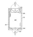
- FIG. 3 is a cross-sectional view showing the configuration of the second flow path through which the cooling medium of the plate fin heat exchanger type condenser flows.
- 4 is a cross-sectional view taken along the line IV-IV in FIG.
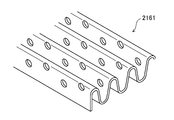
- FIG. 5 is a perspective view illustrating a corrugated fin with a through hole.
- FIG. 1 is a schematic diagram showing the configuration of the condensation system 1.
- the condensation system 1 includes a condenser 2 and a gas-liquid separator 3.
- this condensing system does not limit its application, for example, as a system attached to an air separator, liquefied carbon dioxide (condensate) is recovered by condensing a gas containing carbon dioxide (condensation target gas). It can be used for the purpose.
- the condenser 2 is constituted by a plate fin heat exchanger as described later.
- the condenser 2 condenses the condensation target gas when the cooling fluid cools the condensation target gas.
- a condensate (L) and uncondensed gas (V) flow out as described later. That is, as shown by the black arrows in FIG. 1, the condensation target gas flows into the condenser 2 and the condensed liquid of the gas-liquid mixture flows out.
- the cooling fluid flows into and out of the condenser 2 as indicated by white arrows.
- the gas-liquid separator 3 is connected to the outlet of the condenser 2.
- the gas-liquid separator 3 separates the gas-liquid mixed condensate flowing out of the condenser 2 into a gas and a liquid, and then discharges the gas and the liquid, respectively.
- the specific structure of the gas-liquid separator 3 is not particularly limited, and various known gas-liquid separators can be appropriately employed.
- the gas-liquid separator 3 may be constituted by a gas-liquid separation drum.
- the gas to be condensed flowing into the condenser 2 includes so-called impurities.
- the impurity is a non-condensable gas that does not condense in the temperature zone of the condenser 2.
- the gas flowing out of the condenser 2 includes an uncondensed gas that is an impurity and an uncondensed gas that has not been condensed.
- the gas-liquid separator 3 separates the non-condensed gas and the non-condensed gas from the condensed liquid. In the configuration in which non-condensable gas flows into the gas-liquid separator 3, the capacity of the gas-liquid separator 3 must be increased by that amount.
- the non-condensable gas is positively discharged from the condenser 2 to suppress or prevent the non-condensable gas from flowing into the gas-liquid separator 3. ing.
- the capacity of the gas-liquid separator 3 is made as small as possible.
- the condenser 2 is constituted by a plate fin heat exchanger (that is, a main body).
- the condenser 2 includes a first flow path 21 (see FIG. 2) through which a gas to be condensed flows and a second flow path 22 (see FIG. 3) through which a cooling fluid flows, as shown in FIG. , 22 are alternately stacked via the tube plate 20 that conducts heat.
- FIG. 4 the internal structure of the condenser 2 is drawn larger than the actual size for easy understanding.
- the first flow path 21 is a flow path through which the condensation target gas flows.
- the outer periphery of the first channel 21 is partitioned by a side bar 211, and an inlet 212 into which a gas to be condensed flows and an outlet from which a condensed liquid of gas-liquid mixture flows out on the side surface of the condenser 2.
- 213 and the 2nd outflow port 214 from which a non-condensable gas flows out are provided.
- the inflow port 212 is provided at an upper position on the left side surface in FIG.
- the outflow port 213 is provided at the lower end position on the right side surface in FIG.
- the outflow port 213 is located below the inflow port 212, and the condensation target gas that has flowed in through the inflow port 212 flows downward in the first flow path 21.
- the condensate condensed during that time also flows downward and flows out through the outlet 213.
- the second outlet 214 is provided at the upper end position on the right side in FIG. Therefore, the second outlet 214 is located above the inlet 212.
- the cooling part 215 in which the condensation object gas is cooled by the cooling fluid is set. It should be noted that the condensation target gas can be cooled by the cooling fluid even in parts other than the cooling unit 215.
- Corrugated fins 2151 are disposed in the cooling unit 215. The corrugated fin 2151 divides the cooling unit 215 into a plurality of channels and expands the heat transfer area. Each channel is disposed so as to extend in the vertical direction.
- An inlet distributor 216 is provided between the cooling part 215 and the inlet 212.
- Corrugated fins 2161 are disposed in the distributor unit 216.
- the corrugated fins 2161 are arranged so that the fins extend in the left-right direction.
- the inlet-side distributor 216 distributes the condensation target gas that has flowed into the first flow path 21 through the inlet 212 to each channel of the cooling unit 215.
- An outlet distributor 217 is provided between the cooling part 215 and the outlet 213.
- the distributor 217 is also provided with corrugated fins 2171.
- the corrugated fins 2171 are arranged such that the fins extend in an oblique direction.
- the outlet distributor 217 guides the condensed liquid of the gas-liquid mixture flowing out from each channel of the cooling unit 215 to the outlet 213.
- the upper end of the distributor section 216 on the entry side is open.
- the inlet distributor 216 communicates with the second outlet 214.
- An exhaust part 218 is provided between the inlet-side distributor part 216 and the second outlet 214.
- Two types of corrugated fins 2181 and 2182 are disposed in the exhaust portion 218. One of these (that is, corrugated fin 2181) is disposed so that the fin extends upward, and the other (that is, corrugated fin 2182) is disposed so that the fin extends left and right. .
- the exhaust unit 218 guides non-condensable gas to the second outlet 214.
- corrugated fins 2151 and 2171 disposed in the cooling section 215 and the outlet distributor section 217 may be adopted as the corrugated fins 2151 and 2171 disposed in the cooling section 215 and the outlet distributor section 217.
- the gas to be condensed condenses and becomes a condensed liquid of gas-liquid mixing.
- the corrugated fins 2161 disposed in the inlet-side distributor unit 216 are corrugated fins with through holes. This is because the non-condensable gas is exhausted to the exhaust part 218 through the through holes.
- a perforate type can be illustrated as shown in FIG.
- the corrugated fins 2181 and 2182 disposed in the exhaust part 218 are not particularly limited. However, it is preferable to use corrugated fins with a coarse pitch for smoothly discharging non-condensable gas.
- FIG. 3 shows the configuration of the second flow path 22 in the plate fin heat exchanger type condenser 2.
- the second channel 22 is a channel through which the cooling fluid flows.
- the outer periphery of the second flow path 22 is partitioned by a side bar 221, and an inlet 222 through which cooling fluid flows is provided on the lower surface of the condenser 2, and an outlet through which cooling fluid flows out on the upper surface thereof. 223 are provided respectively.
- a white arrow indicates a flow direction of the cooling fluid, and the cooling fluid flows upward in the second flow path 22.
- the phantom line shown in FIG. 3 is also a header tank attached to the inflow port 222 and the outflow port 223.
- the condenser 2 is a counter flow type in which the fluid to be condensed and the cooling fluid flow so as to face each other.
- the counter flow type heat exchanger has an advantage of high heat exchange efficiency.
- the second flow path 22 can also be divided into an inlet-side distributor part 224, a cooling part 225, and an outlet-side distributor part 226. In each of these portions 224, 225, and 226, appropriate types of corrugated fins are disposed.
- the gas to be condensed flows through the inlet 212 of the first flow path 21.
- the gas to be condensed flows into each channel of the cooling unit 215 from the distributor unit 216 on the inlet side (see arrow V).
- the corrugated fins 2161 with through holes are disposed in the inlet-side distributor unit 216, but most of the gas to be condensed flows into the cooling unit 215 along the corrugated fins.
- the condensation target gas in the first flow path 21 is cooled by the cooling fluid flowing in the second flow path 22, and the condensation target gas is condensed.
- the condenser 2 since the condenser 2 is configured as a counterflow type, the heat exchange efficiency is high and the condensation is performed efficiently.
- the condensate flows downward in the cooling unit 215 along the corrugated fins 2151.
- the gas to be condensed flowing into the condenser 2 includes non-condensable gas.
- the flow velocity of the gas to be condensed in the first flow path 21 (particularly, the flow velocity in the cooling unit 215) is set to be relatively low.
- the inflow speed of the gas to be condensed into the inlet 212 may be set to a relatively low speed. Since the flow velocity is set low, a part of the gas including the non-condensable gas flows upward in the cooling unit 215 facing the main flow from the inlet 212 to the outlet 213. Become.
- the non-condensable gas reaches the inlet distributor 216 from the cooling part 215, passes through the through holes of the corrugated fins 2161, and flows out to the exhaust part 218. In this way, the non-condensable gas is discharged out of the condenser 2 through the second outlet 214 (see the arrow V ′ in FIG. 2).
- the gas flowing upward in the cooling unit 215 includes uncondensed gas to be condensed.
- the cooling unit 215 the gas flowing upward in the channel Then, the condensate flowing downward comes into contact with each other successively, and a rectification effect is obtained in which the purity of the condensate gradually increases. Due to this rectification effect, the purity of the condensate flowing out through the outlet 213 is increased.
- the flow rate of the condensation target gas may be set to a low speed at which a gas containing non-condensable gas can flow from the cooling unit 215 to the exhaust unit 218 via the inlet distributor 216.
- a gas containing non-condensable gas can flow from the cooling unit 215 to the exhaust unit 218 via the inlet distributor 216.
- the flow velocity of the gas to be condensed is high, the gas containing non-condensed gas is pushed by the main flow from the inlet 212 to the outlet 213 and cannot flow upward in the cooling unit 215.
- the flow rate of the condensation target gas is such that non-condensed or non-condensed gas flows upward in the cooling unit 215, and in the cooling unit 215, the contact between the gas and the liquid is repeated and the rectification effect It is more preferable to set the speed so as to obtain a sufficient value.
- the flow velocity of the gas to be condensed may be set not only considering discharging the non-condensable gas from the condenser 2 but also considering the rectification effect so that the purity of the condensate is increased. Good.
- the condenser 2 is configured as a counter flow type, but is not limited to this, and the condenser can be configured as, for example, a parallel flow type or a cross flow type. .
- the counter flow type is preferable.
- injecting the gas to be condensed from the upper part of the condenser 2 and letting out the condensate of the gas-liquid mixture from below increases the condensation efficiency and smoothes out the condensate. This is an advantageous configuration.
- the second outlet 214 that allows the non-condensable gas to flow out needs to be positioned above the inlet 212.
- the plate fin heat exchanger has the arrangement of the inlet and outlet of the second flow path (that is, the cooling fluid) and the arrangement of the inlet and the like of the first flow path. Since it can be set independently, the counterflow type heat exchanger provided with the 2nd outflow port 214 can be comprised easily.
- the plate fin heat exchanger type condenser 2 disclosed herein is not limited to the adoption in the condensing system 1 in which the gas-liquid separator 3 is attached on the outflow side, and all the gas to be condensed is condensed in the condenser. If only the condensate flows out, the plate fin heat exchanger type condenser can be used alone.
Landscapes
- Engineering & Computer Science (AREA)
- Physics & Mathematics (AREA)
- Mechanical Engineering (AREA)
- Thermal Sciences (AREA)
- General Engineering & Computer Science (AREA)
- Chemical & Material Sciences (AREA)
- Chemical Kinetics & Catalysis (AREA)
- Separation By Low-Temperature Treatments (AREA)
- Vaporization, Distillation, Condensation, Sublimation, And Cold Traps (AREA)
Abstract
プレートフィン熱交換器型凝縮器2の本体は、第1流路21内に凝縮対象気体が流入するための流入口212と、第1流路内で凝縮した液体が少なくとも流出するための流出口213と、凝縮対象気体に含まれている不凝縮の気体が第1流路から流出するための第2流出口214と、を有する。第2流出口は、流入口よりも上方位置に設けられている。
Description
ここに開示する技術は、プレートフィン熱交換器型凝縮器、及び、当該凝縮器を備えた凝縮システムに関する。
特許文献1には、冷却流体が溜め置かれた容器内に凝縮対象気体を直接供給するように構成された凝縮器が記載されている。この凝縮器は特に、不凝縮気体を含む凝縮対象気体を凝縮するために、前記容器に不凝縮気体排出弁を取り付けており、不凝縮気体は、この排出弁を通じて容器外に排出するようにしている。
また、特許文献1及び特許文献2には、凝縮器(つまり熱交換器)の排出口に気液分離器を接続し、この気液分離器が気液混合の凝縮液から液体と気体とを分離することが記載されている。
また、熱交換器の一種であるプレートフィン熱交換器は、熱交換効率が高いという利点があり、様々な用途に用いられている。例えば特許文献3には、プレートフィン熱交換器を蒸留装置として用いることが記載されている。
ところで、プレートフィン熱交換器を、凝縮対象気体を凝縮するための凝縮器として用いることが考えられる。その場合に、プレートフィン熱交換器型凝縮器に流入させる凝縮対象気体に、不凝縮の気体(尚、ここで言う不凝縮の気体とは、当該凝縮器の温度帯では凝縮しない気体のことを言う)が含まれている場合には、その不凝縮の気体を含む気液混合の凝縮液が、凝縮器から流出することになる。このため、凝縮器の流出側には、凝縮液のみを分離するための気液分離器が必要となる。また、凝縮器において凝縮対象気体が全て凝縮しないときにも、未凝縮の気体を含む気液混合の凝縮液が流出するため、気液分離器が必要になるが、不凝縮の気体が含まれている場合には、流出する気体の量がその分増えるため、大容量の気液分離器が必要になるという不都合がある。
ここに開示する技術は、かかる点に鑑みてなされたものであり、その目的とするところは、プレートフィン熱交換器によって構成される凝縮器において、流入する凝縮対象気体に不凝縮の気体が含まれるときでも、凝縮器の流出側に接続する気液分離器の容量を小さくする、又は、気液分離器を無くすことを可能にする、ことにある。
ここに開示する技術は、プレートフィン熱交換器型凝縮器に係る。この凝縮器は、凝縮対象気体が流れる第1流路と、前記凝縮対象気体を冷却する冷却流体が流れる第2流路と、前記第1流路及び前記第2流路の間に介在するチューブプレートと、を有するプレートフィン熱交換器によって構成される本体を備える。
そして、前記本体は、前記第1流路内に前記凝縮対象気体が流入するための流入口と、前記第1流路内で凝縮した凝縮液が少なくとも流出するための流出口と、前記凝縮対象気体に含まれている不凝縮の気体が前記第1流路から流出するための第2流出口と、を有し、前記第2流出口は、前記流入口よりも上方位置に設けられている。
ここで、不凝縮の気体とは、前述したように、当該凝縮器の温度帯において凝縮しない気体であり、凝縮対象気体に含まれる不純物ということができる。
この構成によると、第1流路と第2流路と、これら2つの流路間に介在するチューブプレートを有するプレートフィン熱交換器からなる本体において、凝縮対象気体は第1流路内を流れ、凝縮対象気体を冷却する冷却流体は第2流路内を流れる。流入口から第1流路内に流入した凝縮対象気体は凝縮し、凝縮液は流出口から流出する。
前記の構成では、プレートフィン熱交換器からなる本体は、凝縮対象気体に含まれている不凝縮の気体が流出するための第2流出口を有している。つまり、凝縮液が流出する流出口とは別に、第1流路に連通する第2流出口が設けられており、第2流出口は、流入口よりも上方位置に設けられている。これにより、前述の通り、流入口から流入した凝縮対象気体は凝縮して凝縮液が流出口から流出する一方で、その凝縮対象気体に含まれる不凝縮の気体は、その一部又は全部が、上方の第2流出口を通じて、本体外へと流出する。尚、第2流出口を通じて、未凝縮の凝縮対象気体が流出する場合もある。第2流出口を通じて気体が流出する結果、流出口から流出する気体は少なくなる、又は、無くなるため、プレートフィン熱交換器型凝縮器の流出側に接続する気液分離器の容量を小さくする、又は、気液分離器を無くすことが可能になる。
ここに開示するプレートフィン熱交換器型凝縮器はまた、凝縮対象気体が流れる第1流路と、前記凝縮対象気体を冷却する冷却流体が流れる第2流路と、前記第1流路及び前記第2流路の間に介在するチューブプレートと、を有するプレートフィン熱交換器によって構成される本体を備え、前記本体は、前記第1流路内に前記凝縮対象気体が流入するための流入口と、前記第1流路内で凝縮した凝縮液及び未凝縮の気体とが少なくとも流出するための流出口と、前記凝縮対象気体に含まれている不凝縮の気体が流出するための第2流出口と、を有し、前記第2流出口は、前記流入口よりも上方位置に設けられている。
この構成によると、前記と同様に、第1流路と第2流路と、これら2つの流路間に介在するチューブプレートを有するプレートフィン熱交換器からなる本体において、凝縮対象気体は第1流路内を流れ、凝縮対象気体を冷却する冷却流体は第2流路内を流れる。凝縮対象気体は第1流路内で凝縮し、凝縮液及び、本体において凝縮しきれなかった未凝縮の凝縮対象気体は、流出口から流出する。つまり、流出口からは気液混合の凝縮液が流出する。
これに対し、凝縮対象気体に含まれる不凝縮の気体の一部又は全部は、第2流出口を通じて本体外へと流出する。尚、第2流出口から未凝縮の凝縮対象気体が流出する場合もある。少なくとも不凝縮の気体が、第2流出口を通じて流出するため、流出口から流出する不凝縮の気体は少なくなる、又は、無くなる。その結果、プレートフィン熱交換器型凝縮器の流出側に接続する気液分離器の容量を小さくすることが可能になる。
前記流出口は、前記流入口よりも下方位置に設けられ、前記第1流路には、前記流入口と前記流出口との間に、前記凝縮対象気体が前記冷却流体によって冷却される冷却部が設定されていると共に、当該冷却部には、コルゲートフィンが配設されており、前記凝縮対象気体の前記第1流路内の流速は、前記不凝縮の気体を含む気体が前記冷却部から前記第2流出口に向かって上昇することが可能な低速度に設定されている、としてもよい。
これによると、流入口から流入する凝縮対象気体は、第1流路内の流速が低いため、第1流路の冷却部内を、流出口に向かって下向きに、ゆっくりと流れるようになる。不凝縮の気体が流出する第2流出口は、流入口よりも上方に位置しているため、不凝縮の気体は、流入口から流出口に向かって下方に流れる凝縮対象気体及び凝縮液とは異なり、冷却部から第2流出口に向かって上向きに流れなければならない。前述の通り、凝縮対象気体の第1流路内の流速を低くすることは、不凝縮の気体を含む気体(つまり、未凝縮の気体も含まれる)が、凝縮対象気体の主流に逆らって上向きに流れることを許容する。その結果、不凝縮の気体を、第2流出口を通じて効率的に、本体外に排出することが可能になる。尚、凝縮対象気体の第1流路内の流速を低くするために、凝縮対象気体の流入口への流入速度を低く設定してもよい。
また、前述の通り、凝縮液は、コルゲートフィンが配設された冷却部内を上から下向きに流れる一方で、不凝縮の気体及び未凝縮の気体を含む気体は、コルゲートフィンが配設された冷却部内を下から上向きに流れる。こうして、冷却部内においては、凝縮液と未凝縮の気体との接触が繰り返される。流出口に向かって下方に流れる凝縮液は、その純度を次第に高めるようになる。すなわち、凝縮対象気体の第1流路内の流速を低くすることによって、プレートフィン熱交換器型凝縮器の第1流路における冷却部では、精留効果を得ることができる。その結果、流出口から流出する凝縮液の純度が高まる。
前記第1流路内には、当該第1流路内を複数のチャンネルに区画するコルゲートフィンが配設されていると共に、前記第1流路の前記流入口と前記チャンネルとの間には、前記流入口から流入した前記凝縮対象気体を前記チャンネルに分配するためのコルゲートフィンが配設されたディストリビュータ部が設けられ、前記ディストリビュータ部は、前記第2流出口に連通しており、前記ディストリビュータ部に配設されたコルゲートフィンは、透孔付きのコルゲートフィンである、としてもよい。
流入口を通じて第1流路内に流入した凝縮対象気体は、ディストリビュータ部に配設されているコルゲートフィンによって、冷却部に設けられた複数のチャンネルに分配される。ディストリビュータ部に配設されたコルゲートフィンは、透孔付きのコルゲートフィンであるため、不凝縮の気体を含む気体は、この透孔を通じて、ディストリビュータ部から第2流出口に流れることが可能になる。つまり、透孔付きのコルゲートフィンは、プレートフィン熱交換器型の本体において、凝縮対象気体を分配する機能と、不凝縮の気体を含む気体を第1流路内から流出させる機能と、を兼ねる。
前記本体は、前記第1流路の前記凝縮対象気体と前記第2流路の前記冷却流体とが向かい合う方向に流れる対向流型に構成されている、としてもよい。
対向流型の熱交換器は熱交換効率が高いため、本体を対向流型に構成することによって、凝縮器の性能が向上する。また、プレートフィン熱交換器は、第1流路と第2流路とがチューブプレートを介して並設している構造であるため、第1流路の流入口及び流出口と、第2流路の流入口及び流出口との配置を、比較的自由に設定することが可能である。つまり、プレートフィン熱交換器では、第1流路の流出口を、流入口よりも下方に位置づけると、上から順に、第2流出口、流入口及び流出口の順番で第1流路の各開口が配置される一方で、対向流型となるように、第2流路の流入口を下に、流出口を上に配置することが容易に実現する。
ここに開示する技術はまた、凝縮システムに係り、このシステムは、凝縮対象気体を凝縮する凝縮器と、前記凝縮器の流出口に接続されかつ、当該凝縮器から流出する気液混合の凝縮液から、凝縮液を分離する気液分離器と、を備える。
そして、前記凝縮器は、前記凝縮対象気体が流れる第1流路と、前記凝縮対象気体を冷却する冷却流体が流れる第2流路と、前記第1流路及び前記第2流路の間に介在するチューブプレートと、を有するプレートフィン熱交換器によって構成され、前記凝縮器は、前記第1流路内に前記凝縮対象気体が流入するための流入口と、前記第1流路内で凝縮した凝縮液及び未凝縮の気体が少なくとも流出するための前記流出口と、前記凝縮対象気体に含まれている不凝縮の気体が流出するための第2流出口と、を有し、前記第2流出口は、前記流入口よりも上方位置に設けられている。
この構成によると、前述したように、不凝縮の気体を、第2流出口を通じて凝縮器から排出するため、凝縮器に接続された気液分離器に流入する気体(主に、未凝縮の気体を含む)を少なくすることが可能になる。その結果、プレートフィン熱交換器型凝縮器と気液分離器とを備えた凝縮システムにおいて、気液分離器の容量を小さくすることが可能になる。
以上説明したように、前記プレートフィン熱交換器型凝縮器、及び、凝縮システムによると、プレートフィン熱交換器型の本体に第2流出口を設け、この第2流出口を通じて不凝縮の気体を本体から流出することで、本体の流出口から流出する気体を少なく、又は、無くすことが可能になり、この本体に接続される気液分離器の容積を小さく、又は、気液分離器を無くすことが可能になる。
以下、プレートフィン熱交換器型凝縮器及び当該凝縮器を備えた凝縮システムの実施形態を図面に基づいて説明する。図1は、凝縮システム1の構成を示す概略図である。凝縮システム1は、凝縮器2と、気液分離器3とを備えて構成される。この凝縮システムは、その用途を限定するものではないが、例えば空気分離器に付随するシステムとして、炭酸ガスを含むガス(凝縮対象気体)を凝縮することによって、液化炭酸ガス(凝縮液)を回収する用途で用いることができる。
凝縮器2は、後述の通り、プレートフィン熱交換器によって構成されている。凝縮器2は、冷却流体が凝縮対象気体を冷却することにより、凝縮対象気体を凝縮する。凝縮器2からは、凝縮液(L)と、後述の通り未凝縮の気体(V)とが流出する。つまり、凝縮器2には、図1に黒矢印で示すように、凝縮対象気体が流入すると共に、気液混合の凝縮液が流出する。また、凝縮器2には、白抜きの矢印で示すように、冷却流体が流入及び流出する。
気液分離器3は、凝縮器2の流出口に接続されている。気液分離器3は、凝縮器2から流出した気液混合の凝縮液を気体と液体とに分離した上で、気体及び液体をそれぞれ排出する。気液分離器3の具体的な構造に関しては、特に限定はなく、公知の様々な構成の気液分離器を、適宜採用することが可能である。気液分離器3を、例えば気液分離ドラムによって構成してもよい。
ここで、凝縮器2に流入する凝縮対象気体には、いわゆる不純物も含まれている。不純物は、当該凝縮器2の温度帯では凝縮しない不凝縮の気体である。また、凝縮器2において、凝縮対象気体が全て凝縮するとは限らない。従って、凝縮器2から流出する気体には、不純物である不凝縮の気体、及び、凝縮しなかった未凝縮の気体が含まれる。気液分離器3は、これら不凝縮の気体及び未凝縮の気体と、凝縮液とを分離する。気液分離器3に不凝縮の気体が流入する構成では、その分だけ、気液分離器3の容量を大きくしなければならない。ここに開示するプレートフィン熱交換器型凝縮器2では、不凝縮の気体を、凝縮器2から積極的に排出し、気液分離器3に不凝縮の気体が流入することを抑制又は防止している。こうして、この凝縮システムでは、気液分離器3の容量をできるだけ小さくする。以下、プレートフィン熱交換器型凝縮器2の構成について、図2~図5を参照しながら、さらに詳細に説明する。
凝縮器2は、前述の通り、プレートフィン熱交換器(つまり、本体)によって構成されている。凝縮器2は、凝縮対象気体が流れる第1流路21(図2参照)と、冷却流体が流れる第2流路22(図3参照)とが、図4に示すように、両流路21、22間の伝熱を行うチューブプレート20を介して、交互に積層して構成されている。尚、図4は、理解容易のために、凝縮器2の内部構造を、実際よりも大きく描いている。
第1流路21は、前述の通り、凝縮対象気体が流れる流路である。第1流路21は、その外周囲がサイドバー211によって区画されると共に、凝縮器2の側面には、凝縮対象気体が流入する流入口212と、気液混合の凝縮液が流出する流出口213と、不凝縮の気体が流出する第2流出口214とが設けられている。このうち、流入口212は、図2における紙面左側の側面における、上方位置に設けられている。流出口213は、図2における紙面右側の側面における、下端位置に設けられている。従って、流出口213は、流入口212よりも下方に位置し、流入口212を通じて流入した凝縮対象気体は、第1流路21内を下方に流れる。その間に凝縮した凝縮液もまた、下方に流れるようになり、流出口213を通じて流出する。
第2流出口214は、図2における紙面右側の側面における、上端位置に設けられている。従って、第2流出口214は、流入口212よりも上方に位置している。
尚、図2における仮想線はそれぞれ、流入口212、流出口213及び第2流出口214に取り付けられるヘッダタンクを示している。
流入口212と流出口213との間には、凝縮対象気体が冷却流体によって冷却される冷却部215が設定されている。尚、凝縮対象気体は、この冷却部215以外の部位においても、冷却流体によって冷却され得る。冷却部215には、コルゲートフィン2151が配設されている。コルゲートフィン2151は、冷却部215を、複数のチャンネルに区画すると共に伝熱面積を拡大する。各チャンネルは、上下方向に延びるように配設される。
冷却部215と流入口212との間には、入側のディストリビュータ部216が設けられる。このディストリビュータ部216には、コルゲートフィン2161が配設されている。このコルゲートフィン2161は、フィンが左右方向に延びるように配設される。入側のディストリビュータ部216は、流入口212を介して第1流路21内に流入した凝縮対象気体を、冷却部215の各チャンネルに分配する。
冷却部215と流出口213との間には、出側のディストリビュータ部217が設けられる。このディストリビュータ部217にも、コルゲートフィン2171が配設されている。コルゲートフィン2171は、フィンが斜め方向に延びるように配設される。出側のディストリビュータ部217は、冷却部215の各チャンネルから流出した気液混合の凝縮液を、流出口213に導く。尚、出側のディストリビュータ部217におけるコルゲートフィン2171の配置態様に、特に制限はない。
第1流路21において、入側のディストリビュータ部216の上端は開放されている。これにより、入側のディストリビュータ部216は、第2流出口214に連通している。入側のディストリビュータ部216と第2流出口214との間には、排気部218が設けられている。排気部218には、2種類のコルゲートフィン2181、2182が配設されている。このうちの一つ(つまり、コルゲートフィン2181)は、フィンが上方に延びるように配設される一方、もう一つ(つまり、コルゲートフィン2182)は、フィンが左右に延びるように配設される。排気部218は、不凝縮の気体を第2流出口214に導く。
冷却部215及び出側のディストリビュータ部217に配設するコルゲートフィン2151、2171としては、どのような種類のコルゲートフィンを採用してもよい。但し、凝縮器2における、特に流出口213側では、凝縮対象気体が凝縮をして気液混合の凝縮液となる。このことから、冷却部215及び/又は出側のディストリビュータ部217において、チャンネル間の偏流を防止する上では、例えばパーホレート型等の透孔付きのコルゲートフィンを配設することが好ましい(図5参照)。
入側のディストリビュータ部216に配設されるコルゲートフィン2161は、透孔付きのコルゲートフィンである。これは、不凝縮の気体を、透孔を通じて排気部218に排気するためである。透孔付きのディストリビュータフィンとしては、図5に示すように、パーホレート型を例示することが可能である。
排気部218に配設されるコルゲートフィン2181、2182は、特に制限はない。但し、不凝縮の気体の排気をスムースに行う上で、ピッチの粗いコルゲートフィンを採用することが好ましい。
図3は、プレートフィン熱交換器型凝縮器2における第2流路22の構成を示している。第2流路22は、前述の通り、冷却流体が流れる流路である。第2流路22は、その外周囲がサイドバー221によって区画されると共に、凝縮器2の下面には、冷却流体が流入する流入口222が、その上面には、冷却流体が流出する流出口223が、それぞれ設けられている。白抜きの矢印は冷却流体の流れ方向を示しており、冷却流体は、第2流路22内を上方に流れる。尚、図3に示す仮想線も、流入口222及び流出口223に取り付けられるヘッダタンクである。凝縮器2は、凝縮対象流体と冷却流体とが対向するように流れる対向流型である。対向流型の熱交換器は、熱交換効率が高いという利点がある。
第2流路22も、入側のディストリビュータ部224、冷却部225、及び出側のディストリビュータ部226に区分することが可能である。これらの各部224、225、226には、適宜の種類のコルゲートフィンが配設されている。
このような構成のプレートフィン熱交換器型凝縮器2では、第1流路21の流入口212を通じて、凝縮対象気体が流入する。
凝縮対象気体は、入側のディストリビュータ部216から、冷却部215の各チャンネルに流入する(Vの矢印参照)。前述の通り、入側のディストリビュータ部216には、透孔付きのコルゲートフィン2161が配設されているが、凝縮対象気体のほとんどは、コルゲートフィンに沿って、冷却部215に流入する。
冷却部215においては、第1流路21の凝縮対象気体が、第2流路22を流れる冷却流体によって冷却され、凝縮対象気体は凝縮する。ここで、前述の通り、この凝縮器2は、対向流型に構成されているため、熱交換効率が高く、凝縮が効率的に行われる。凝縮液は、冷却部215内を、コルゲートフィン2151に沿って下方に流れるようになる。
凝縮器2に流入する凝縮対象気体には、不凝縮の気体が含まれている。ここで、凝縮対象気体の第1流路21内の流速(特に、冷却部215における流速)は、比較的低速に設定されている。例えば凝縮対象気体の、流入口212への流入速度を、比較的低速に設定してもよい。流速が低く設定されていることから、不凝縮の気体を含む気体の一部は、流入口212から流出口213へと向かう主流に対向して、冷却部215内を上方に向かって流れるようになる。不凝縮の気体は、冷却部215から入側のディストリビュータ部216に至り、コルゲートフィン2161の透孔を通過して、排気部218へと流出するようになる。こうして不凝縮の気体は、第2流出口214を通じて凝縮器2外に排出される(図2のV’の矢印参照)。
また、冷却部215において上方に流れる気体には、不凝縮の気体の他にも、未凝縮の凝縮対象気体も含まれているが、この冷却部215においては、チャンネル内を上方に流れる気体と、下方に流れる凝縮液とが逐次接触するようになり、凝縮液の純度が次第に高まる精留効果が得られる。この精留効果によって、流出口213を通じて流出する凝縮液の純度が高まる。
こうして、不凝縮の気体を、第2流出口214を通じて凝縮器2外に排出することにより、流出口213を通じて流出する気液混合の凝縮液における気体の量を減らすことが可能になる(V+Lの矢印参照)。このことは、凝縮器2に接続される気液分離器3の容量を小さくすることを可能にする。
ここで、凝縮対象気体の流速は、不凝縮の気体を含む気体が冷却部215から入側のディストリビュータ部216を介して排気部218へと流れることが可能な程度の低い速度に設定することが好ましい。凝縮対象気体の流速が高いと、不凝縮の気体を含む気体が、流入口212から流出口213へと向かう主流に押されて、冷却部215において上方に向かって流れることができなくなる。
また、凝縮対象気体の流速は、不凝縮又は未凝縮の気体が、冷却部215において上方に向かって流れるだけでなく、その冷却部215において、気体と液体との接触が繰り返されて精留効果が十分に得られるような低い速度に設定することがさらに好ましい。つまり、凝縮対象気体の流速は、不凝縮の気体を凝縮器2から排出することだけを考慮するのではなく、凝縮液の純度が高まるように精留効果をも考慮して、設定してもよい。
尚、前記の構成では、凝縮器2を対向流型に構成しているものの、これに限定されるものではなく、凝縮器は、例えば並行流型や直交流型に構成することも可能である。但し、熱交換効率を高める観点からは、対向流型であることが好ましい。また、凝縮器2においては、凝縮対象気体を凝縮器2の上部から流入させ、気液混合の凝縮液を下方から流出させることが、凝縮効率を高めると共に、凝縮液の流出をスムースにする上で有利な構成である。さらに、不凝縮の気体を流出させる第2流出口214は、流入口212よりも上方に位置づける必要がある。このような構成を採用する上で、プレートフィン熱交換器は、第2流路の(つまり、冷却流体の)流入口及び流出口の配置を、第1流路の流入口等の配置とは独立して設定することが可能であるから、第2流出口214を備えた対向流型の熱交換器を、容易に構成することが可能になる。
尚、ここに開示するプレートフィン熱交換器型凝縮器2は、その流出側に気液分離器3が取り付けられる凝縮システム1への採用に限らず、当該凝縮器内において凝縮対象気体が全て凝縮し、凝縮液のみが流出するのであれば、プレートフィン熱交換器型凝縮器単体で用いることも可能である。
1 凝縮システム
2 プレートフィン熱交換器型凝縮器(本体)
20 チューブプレート
21 第1流路
22 第2流路
212 流入口
213 流出口
214 第2流出口
215 冷却部
2151 コルゲートフィン
216 入側のディストリビュータ部
2161 透孔付きのコルゲートフィン
3 気液分離器
2 プレートフィン熱交換器型凝縮器(本体)
20 チューブプレート
21 第1流路
22 第2流路
212 流入口
213 流出口
214 第2流出口
215 冷却部
2151 コルゲートフィン
216 入側のディストリビュータ部
2161 透孔付きのコルゲートフィン
3 気液分離器
Claims (6)
- 凝縮対象気体が流れる第1流路と、前記凝縮対象気体を冷却する冷却流体が流れる第2流路と、前記第1流路及び前記第2流路の間に介在するチューブプレートと、を有するプレートフィン熱交換器によって構成される本体を備え、
前記本体は、前記第1流路内に前記凝縮対象気体が流入するための流入口と、前記第1流路内で凝縮した凝縮液が少なくとも流出するための流出口と、前記凝縮対象気体に含まれている不凝縮の気体が前記第1流路から流出するための第2流出口と、を有し、
前記第2流出口は、前記流入口よりも上方位置に設けられているプレートフィン熱交換器型凝縮器。 - 凝縮対象気体が流れる第1流路と、前記凝縮対象気体を冷却する冷却流体が流れる第2流路と、前記第1流路及び前記第2流路の間に介在するチューブプレートと、を有するプレートフィン熱交換器によって構成される本体を備え、
前記本体は、前記第1流路内に前記凝縮対象気体が流入するための流入口と、前記第1流路内で凝縮した凝縮液及び未凝縮の気体とが少なくとも流出するための流出口と、前記凝縮対象気体に含まれている不凝縮の気体が流出するための第2流出口と、を有し、
前記第2流出口は、前記流入口よりも上方位置に設けられているプレートフィン熱交換器型凝縮器。 - 請求項1又は2に記載のプレートフィン熱交換器型凝縮器において、
前記流出口は、前記流入口よりも下方位置に設けられ、
前記第1流路には、前記流入口と前記流出口との間に、前記凝縮対象気体が前記冷却流体によって冷却される冷却部が設定されていると共に、当該冷却部には、コルゲートフィンが配設されており、
前記凝縮対象気体の前記第1流路内の流速は、前記不凝縮の気体を含む気体が前記冷却部から前記第2流出口に向かって上昇することが可能な低速度に設定されているプレートフィン熱交換器型凝縮器。 - 請求項1~3のいずれか1項に記載のプレートフィン熱交換器型凝縮器において、
前記第1流路内には、当該第1流路内を複数のチャンネルに区画するコルゲートフィンが配設されていると共に、前記第1流路の前記流入口と前記チャンネルとの間には、前記流入口から流入した前記凝縮対象気体を前記チャンネルに分配するためのコルゲートフィンが配設されたディストリビュータ部が設けられ、
前記ディストリビュータ部は、前記第2流出口に連通しており、
前記ディストリビュータ部に配設されたコルゲートフィンは、透孔付きのコルゲートフィンであるプレートフィン熱交換器型凝縮器。 - 請求項1~4のいずれか1項に記載のプレートフィン熱交換器型凝縮器において、
前記本体は、前記第1流路の前記凝縮対象気体と前記第2流路の前記冷却流体とが向かい合う方向に流れる対向流型に構成されているプレートフィン熱交換器型凝縮器。 - 凝縮対象気体を凝縮する凝縮器と、
前記凝縮器の流出口に接続されかつ、当該凝縮器から流出する気液混合の凝縮液から、凝縮液を分離する気液分離器と、を備え、
前記凝縮器は、
前記凝縮対象気体が流れる第1流路と、前記凝縮対象気体を冷却する冷却流体が流れる第2流路と、前記第1流路及び前記第2流路の間に介在するチューブプレートと、を有するプレートフィン熱交換器によって構成され、
前記凝縮器は、前記第1流路内に前記凝縮対象気体が流入するための流入口と、前記第1流路内で凝縮した凝縮液及び未凝縮の気体が少なくとも流出するための前記流出口と、前記凝縮対象気体に含まれている不凝縮の気体が流出するための第2流出口と、を有し、
前記第2流出口は、前記流入口よりも上方位置に設けられている凝縮システム。
Applications Claiming Priority (2)
| Application Number | Priority Date | Filing Date | Title |
|---|---|---|---|
| JP2013257379A JP2015114062A (ja) | 2013-12-12 | 2013-12-12 | プレートフィン熱交換器型凝縮器、及び、凝縮システム |
| JP2013-257379 | 2013-12-12 |
Publications (1)
| Publication Number | Publication Date |
|---|---|
| WO2015087552A1 true WO2015087552A1 (ja) | 2015-06-18 |
Family
ID=53370877
Family Applications (1)
| Application Number | Title | Priority Date | Filing Date |
|---|---|---|---|
| PCT/JP2014/006189 Ceased WO2015087552A1 (ja) | 2013-12-12 | 2014-12-12 | プレートフィン熱交換器型凝縮器、及び、凝縮システム |
Country Status (2)
| Country | Link |
|---|---|
| JP (1) | JP2015114062A (ja) |
| WO (1) | WO2015087552A1 (ja) |
Cited By (1)
| Publication number | Priority date | Publication date | Assignee | Title |
|---|---|---|---|---|
| EP4428475A1 (de) * | 2023-03-08 | 2024-09-11 | Linde GmbH | Wärmetauscher sowie zugehörige anlagen und verfahren |
Citations (4)
| Publication number | Priority date | Publication date | Assignee | Title |
|---|---|---|---|---|
| JPH0346760U (ja) * | 1989-08-30 | 1991-04-30 | ||
| JPH10148480A (ja) * | 1996-11-15 | 1998-06-02 | Tlv Co Ltd | 熱交換器 |
| JPH10197169A (ja) * | 1997-01-14 | 1998-07-31 | Kobe Steel Ltd | デフレグメータ |
| JP2007303783A (ja) * | 2006-05-15 | 2007-11-22 | Tlv Co Ltd | 熱交換器 |
-
2013
- 2013-12-12 JP JP2013257379A patent/JP2015114062A/ja active Pending
-
2014
- 2014-12-12 WO PCT/JP2014/006189 patent/WO2015087552A1/ja not_active Ceased
Patent Citations (4)
| Publication number | Priority date | Publication date | Assignee | Title |
|---|---|---|---|---|
| JPH0346760U (ja) * | 1989-08-30 | 1991-04-30 | ||
| JPH10148480A (ja) * | 1996-11-15 | 1998-06-02 | Tlv Co Ltd | 熱交換器 |
| JPH10197169A (ja) * | 1997-01-14 | 1998-07-31 | Kobe Steel Ltd | デフレグメータ |
| JP2007303783A (ja) * | 2006-05-15 | 2007-11-22 | Tlv Co Ltd | 熱交換器 |
Cited By (2)
| Publication number | Priority date | Publication date | Assignee | Title |
|---|---|---|---|---|
| EP4428475A1 (de) * | 2023-03-08 | 2024-09-11 | Linde GmbH | Wärmetauscher sowie zugehörige anlagen und verfahren |
| WO2024183948A1 (de) | 2023-03-08 | 2024-09-12 | Linde Gmbh | Wärmetauscher sowie zugehörige anlagen und verfahren |
Also Published As
| Publication number | Publication date |
|---|---|
| JP2015114062A (ja) | 2015-06-22 |
Similar Documents
| Publication | Publication Date | Title |
|---|---|---|
| JP6701372B2 (ja) | 熱交換器 | |
| CN105593625B (zh) | 热交换器 | |
| US10408535B2 (en) | Multistage bath condenser-reboiler | |
| JP2014020755A (ja) | 流下液膜式蒸発器 | |
| KR101447458B1 (ko) | 환류 응축기 | |
| US10012439B2 (en) | Condenser-reboiler system and method | |
| WO2000020812A1 (en) | Downflow liquid film type condensation evaporator | |
| WO2015087552A1 (ja) | プレートフィン熱交換器型凝縮器、及び、凝縮システム | |
| KR101742242B1 (ko) | 쿨링 모듈 | |
| JP5338950B2 (ja) | 熱交換器 | |
| JP2014020753A (ja) | 流下液膜式蒸発器 | |
| US12379141B2 (en) | Liquid refrigerant sprayer and falling liquid film type evaporator | |
| WO2019219076A1 (zh) | 换热器 | |
| JP5087030B2 (ja) | 熱交換型蒸留装置 | |
| US20160367908A1 (en) | Separation column having an internal heat exchanger | |
| KR101146106B1 (ko) | 판형 열교환기 | |
| JP7212919B2 (ja) | 凝縮器 | |
| JP4577908B2 (ja) | 吸収冷温水機用再生器 | |
| JP4704928B2 (ja) | 熱交換型蒸留装置 | |
| JP2003065695A (ja) | 冷凍機用凝縮器 | |
| JP5848977B2 (ja) | 吸収式冷凍機 | |
| JP6477314B2 (ja) | 冷媒蒸発器 | |
| JPH10197169A (ja) | デフレグメータ | |
| JP5094261B2 (ja) | 凝縮装置 | |
| KR20150115707A (ko) | 냉수탱크 |
Legal Events
| Date | Code | Title | Description |
|---|---|---|---|
| 121 | Ep: the epo has been informed by wipo that ep was designated in this application |
Ref document number: 14869730 Country of ref document: EP Kind code of ref document: A1 |
|
| NENP | Non-entry into the national phase |
Ref country code: DE |
|
| 122 | Ep: pct application non-entry in european phase |
Ref document number: 14869730 Country of ref document: EP Kind code of ref document: A1 |