WO2015083773A1 - 膜分離装置、循環水利用システム - Google Patents
膜分離装置、循環水利用システム Download PDFInfo
- Publication number
- WO2015083773A1 WO2015083773A1 PCT/JP2014/082078 JP2014082078W WO2015083773A1 WO 2015083773 A1 WO2015083773 A1 WO 2015083773A1 JP 2014082078 W JP2014082078 W JP 2014082078W WO 2015083773 A1 WO2015083773 A1 WO 2015083773A1
- Authority
- WO
- WIPO (PCT)
- Prior art keywords
- water
- membrane
- separation membrane
- treated
- pressure difference
- Prior art date
- Legal status (The legal status is an assumption and is not a legal conclusion. Google has not performed a legal analysis and makes no representation as to the accuracy of the status listed.)
- Ceased
Links
Images

Classifications
-
- B—PERFORMING OPERATIONS; TRANSPORTING
- B01—PHYSICAL OR CHEMICAL PROCESSES OR APPARATUS IN GENERAL
- B01D—SEPARATION
- B01D61/00—Processes of separation using semi-permeable membranes, e.g. dialysis, osmosis or ultrafiltration; Apparatus, accessories or auxiliary operations specially adapted therefor
- B01D61/02—Reverse osmosis; Hyperfiltration ; Nanofiltration
- B01D61/025—Reverse osmosis; Hyperfiltration
-
- C—CHEMISTRY; METALLURGY
- C02—TREATMENT OF WATER, WASTE WATER, SEWAGE, OR SLUDGE
- C02F—TREATMENT OF WATER, WASTE WATER, SEWAGE, OR SLUDGE
- C02F1/00—Treatment of water, waste water, or sewage
- C02F1/008—Control or steering systems not provided for elsewhere in subclass C02F
-
- C—CHEMISTRY; METALLURGY
- C02—TREATMENT OF WATER, WASTE WATER, SEWAGE, OR SLUDGE
- C02F—TREATMENT OF WATER, WASTE WATER, SEWAGE, OR SLUDGE
- C02F1/00—Treatment of water, waste water, or sewage
- C02F1/44—Treatment of water, waste water, or sewage by dialysis, osmosis or reverse osmosis
-
- B—PERFORMING OPERATIONS; TRANSPORTING
- B01—PHYSICAL OR CHEMICAL PROCESSES OR APPARATUS IN GENERAL
- B01D—SEPARATION
- B01D2311/00—Details relating to membrane separation process operations and control
- B01D2311/25—Recirculation, recycling or bypass, e.g. recirculation of concentrate into the feed
-
- B—PERFORMING OPERATIONS; TRANSPORTING
- B01—PHYSICAL OR CHEMICAL PROCESSES OR APPARATUS IN GENERAL
- B01D—SEPARATION
- B01D2313/00—Details relating to membrane modules or apparatus
- B01D2313/36—Energy sources
- B01D2313/367—Renewable energy sources, e.g. wind or solar sources
-
- C—CHEMISTRY; METALLURGY
- C02—TREATMENT OF WATER, WASTE WATER, SEWAGE, OR SLUDGE
- C02F—TREATMENT OF WATER, WASTE WATER, SEWAGE, OR SLUDGE
- C02F1/00—Treatment of water, waste water, or sewage
- C02F1/02—Treatment of water, waste water, or sewage by heating
-
- C—CHEMISTRY; METALLURGY
- C02—TREATMENT OF WATER, WASTE WATER, SEWAGE, OR SLUDGE
- C02F—TREATMENT OF WATER, WASTE WATER, SEWAGE, OR SLUDGE
- C02F1/00—Treatment of water, waste water, or sewage
- C02F1/44—Treatment of water, waste water, or sewage by dialysis, osmosis or reverse osmosis
- C02F1/441—Treatment of water, waste water, or sewage by dialysis, osmosis or reverse osmosis by reverse osmosis
-
- C—CHEMISTRY; METALLURGY
- C02—TREATMENT OF WATER, WASTE WATER, SEWAGE, OR SLUDGE
- C02F—TREATMENT OF WATER, WASTE WATER, SEWAGE, OR SLUDGE
- C02F1/00—Treatment of water, waste water, or sewage
- C02F1/44—Treatment of water, waste water, or sewage by dialysis, osmosis or reverse osmosis
- C02F1/442—Treatment of water, waste water, or sewage by dialysis, osmosis or reverse osmosis by nanofiltration
-
- C—CHEMISTRY; METALLURGY
- C02—TREATMENT OF WATER, WASTE WATER, SEWAGE, OR SLUDGE
- C02F—TREATMENT OF WATER, WASTE WATER, SEWAGE, OR SLUDGE
- C02F1/00—Treatment of water, waste water, or sewage
- C02F1/44—Treatment of water, waste water, or sewage by dialysis, osmosis or reverse osmosis
- C02F1/444—Treatment of water, waste water, or sewage by dialysis, osmosis or reverse osmosis by ultrafiltration or microfiltration
-
- C—CHEMISTRY; METALLURGY
- C02—TREATMENT OF WATER, WASTE WATER, SEWAGE, OR SLUDGE
- C02F—TREATMENT OF WATER, WASTE WATER, SEWAGE, OR SLUDGE
- C02F2201/00—Apparatus for treatment of water, waste water or sewage
- C02F2201/009—Apparatus with independent power supply, e.g. solar cells, windpower or fuel cells
-
- C—CHEMISTRY; METALLURGY
- C02—TREATMENT OF WATER, WASTE WATER, SEWAGE, OR SLUDGE
- C02F—TREATMENT OF WATER, WASTE WATER, SEWAGE, OR SLUDGE
- C02F2209/00—Controlling or monitoring parameters in water treatment
- C02F2209/005—Processes using a programmable logic controller [PLC]
-
- C—CHEMISTRY; METALLURGY
- C02—TREATMENT OF WATER, WASTE WATER, SEWAGE, OR SLUDGE
- C02F—TREATMENT OF WATER, WASTE WATER, SEWAGE, OR SLUDGE
- C02F2209/00—Controlling or monitoring parameters in water treatment
- C02F2209/02—Temperature
-
- C—CHEMISTRY; METALLURGY
- C02—TREATMENT OF WATER, WASTE WATER, SEWAGE, OR SLUDGE
- C02F—TREATMENT OF WATER, WASTE WATER, SEWAGE, OR SLUDGE
- C02F2209/00—Controlling or monitoring parameters in water treatment
- C02F2209/03—Pressure
-
- C—CHEMISTRY; METALLURGY
- C02—TREATMENT OF WATER, WASTE WATER, SEWAGE, OR SLUDGE
- C02F—TREATMENT OF WATER, WASTE WATER, SEWAGE, OR SLUDGE
- C02F2209/00—Controlling or monitoring parameters in water treatment
- C02F2209/40—Liquid flow rate
-
- C—CHEMISTRY; METALLURGY
- C02—TREATMENT OF WATER, WASTE WATER, SEWAGE, OR SLUDGE
- C02F—TREATMENT OF WATER, WASTE WATER, SEWAGE, OR SLUDGE
- C02F2307/00—Location of water treatment or water treatment device
- C02F2307/10—Location of water treatment or water treatment device as part of a potable water dispenser, e.g. for use in homes or offices
-
- Y—GENERAL TAGGING OF NEW TECHNOLOGICAL DEVELOPMENTS; GENERAL TAGGING OF CROSS-SECTIONAL TECHNOLOGIES SPANNING OVER SEVERAL SECTIONS OF THE IPC; TECHNICAL SUBJECTS COVERED BY FORMER USPC CROSS-REFERENCE ART COLLECTIONS [XRACs] AND DIGESTS
- Y02—TECHNOLOGIES OR APPLICATIONS FOR MITIGATION OR ADAPTATION AGAINST CLIMATE CHANGE
- Y02A—TECHNOLOGIES FOR ADAPTATION TO CLIMATE CHANGE
- Y02A20/00—Water conservation; Efficient water supply; Efficient water use
- Y02A20/20—Controlling water pollution; Waste water treatment
- Y02A20/208—Off-grid powered water treatment
- Y02A20/212—Solar-powered wastewater sewage treatment, e.g. spray evaporation
-
- Y—GENERAL TAGGING OF NEW TECHNOLOGICAL DEVELOPMENTS; GENERAL TAGGING OF CROSS-SECTIONAL TECHNOLOGIES SPANNING OVER SEVERAL SECTIONS OF THE IPC; TECHNICAL SUBJECTS COVERED BY FORMER USPC CROSS-REFERENCE ART COLLECTIONS [XRACs] AND DIGESTS
- Y02—TECHNOLOGIES OR APPLICATIONS FOR MITIGATION OR ADAPTATION AGAINST CLIMATE CHANGE
- Y02W—CLIMATE CHANGE MITIGATION TECHNOLOGIES RELATED TO WASTEWATER TREATMENT OR WASTE MANAGEMENT
- Y02W10/00—Technologies for wastewater treatment
- Y02W10/30—Wastewater or sewage treatment systems using renewable energies
- Y02W10/37—Wastewater or sewage treatment systems using renewable energies using solar energy
Definitions
- the present disclosure relates to a membrane separation device that separates water to be treated into permeated water and concentrated water using a separation membrane.
- Patent Document 1 discloses a seawater desalination apparatus in which filtered water (water to be treated) obtained by filtering seawater is further subjected to membrane separation into fresh water (permeated water) and high concentration salt water (concentrated water) by a reverse osmosis membrane (separation membrane).
- a configuration is disclosed in which the pressure of the filtered water supplied to the reverse osmosis membrane is adjusted by the output control of the high pressure pump.
- the permeated water for pressure regulation Although there is a merit that the response of the flow rate is relatively high, the pressure difference before and after the separation membrane to increase the permeate flow rate (the pressure of the water to be treated supplied to the separation membrane and the permeated water passing through the separation membrane) If the difference between the pressure and the pressure is excessively increased, the separation membrane may be broken, and the impurities in the water to be treated may not be sufficiently removed.
- At least one embodiment of the present invention has been made in view of the above-mentioned conventional problems, and the object of the present invention is to provide a separation membrane without excessively increasing the pressure difference before and after the separation membrane.
- An object of the present invention is to provide a membrane separation device capable of rapidly obtaining a desired flow rate of permeated water and suppressing breakage of the separation membrane by increasing the flow rate of the permeated water.
- a membrane separation apparatus for separating water to be treated into permeated water and concentrated water by a separation membrane, A pressure pump for pressurizing the water to be treated; A separation membrane configured to be supplied with the water to be treated pressurized by the pressurization pump; Flow meter side means for measuring the flow rate of the permeated water that has permeated the separation membrane, An adjusting means configured to adjust the pressure of the water to be treated supplied to the separation membrane so that the flow rate of the permeated water measured by the flow meter side means approaches a target flow rate; Pressure difference detecting means for detecting a pressure difference before and after the separation membrane; A heating unit configured to heat the water to be treated supplied to the separation membrane when the pressure difference detected by the pressure difference detection unit exceeds a threshold value; Have.
- the membrane separation device In the configuration in which the flow rate of permeated water from the separation membrane approaches the target flow rate by adjusting the pressure of the water to be treated supplied to the separation membrane, there is an advantage that the response of the permeated water flow rate to pressure regulation is relatively high. If the pressure difference before and after the separation membrane is increased excessively in order to increase the flow rate of the permeated water, the separation membrane may be broken and it may not be possible to sufficiently remove the impurities of the water to be treated. Therefore, in the membrane separation device according to the above (1), the water to be treated supplied to the separation membrane is heated by the heating means when the pressure difference across the separation membrane detected by the pressure difference detection means exceeds the threshold. It is configured as follows.
- the temperature of the water to be treated is raised by the heating means, the viscosity of the water to be treated is lowered, so that the permeated water flow rate of the separation membrane under the same pressure condition can be increased. Therefore, as described above, if the water to be treated supplied to the separation membrane by the heating means is heated by the heating means when the pressure difference before and after the separation membrane exceeds the threshold value, the pressure difference before and after the separation membrane is excessive.
- the flow rate of permeated water of the separation membrane can be increased without increasing the size. As a result, it is possible to quickly obtain a permeated water having a desired flow rate and to suppress breakage of the separation membrane.
- the "separation membrane” here is used in the sense that it includes at least a reverse osmosis membrane (RO membrane), a microfiltration membrane (MF membrane), an ultrafiltration membrane (UF membrane), and a nanofiltration membrane (NF membrane) ing.
- RO membrane reverse osmosis membrane
- MF membrane microfiltration membrane
- UF membrane ultrafiltration membrane
- NF membrane nanofiltration membrane
- the threshold value is set to a smaller value in the case where the predetermined period is exceeded than in the case where the use period of the separation membrane is within the predetermined period.
- the threshold value is smaller when the use period of the separation membrane exceeds the predetermined period than when the predetermined period.
- the adjusting unit makes the pressure of the water to be supplied to the separation membrane constant when the pressure difference exceeds a threshold.
- the adjusting means is configured to adjust the pressure of the water to be supplied to the separation membrane by adjusting the output of the pressure pump.
- the adjustment means includes a throttling means capable of adjusting the flow area of the flow path in the flow path between the pressure pump and the separation membrane, and the flow area is adjusted by the throttling means. It is comprised so that the pressure of the said to-be-processed water supplied to a separation membrane may be adjusted.
- the output of the pressure pump is compared with the case where the pressure is adjusted by the output adjustment of the pressure pump. Since the inverter etc. which are used for adjustment are unnecessary, simplification of an electric installation can be achieved.
- the membrane separation device in the membrane separation device according to any one of (1) to (5) above, It is further equipped with a solar power generation device that generates electricity by solar energy,
- the heating unit is configured to heat the water to be treated using the power generated by the solar power generation device even when the pressure difference detected by the pressure difference detection unit does not exceed the threshold. Be done.
- the power from the solar power generation apparatus be used as directly as possible without using a battery or the like. Therefore, in the membrane separation device according to the above (6), even if the pressure difference detected by the pressure difference detection means does not exceed the threshold value, heating of the water to be treated is performed using the power generation output of the solar power generation device In the above configuration, the viscosity of the water to be treated can be reduced, and energy can be efficiently used in the entire membrane separation apparatus.
- the system further includes a solar water heater that heats the water to be treated even when the pressure difference detected by the pressure difference detection means does not exceed the threshold.
- a solar water heater that heats the water to be treated even when the pressure difference detected by the pressure difference detection means does not exceed the threshold.
- the circulating water utilization system according to some embodiments, Circulation channels where circulating water flows, The circulating water discharged from a water demand body comprising a plurality of small water demand bodies consisting of at least one of a residence, a tenant, and an office using the circulating water flowing through the circulation flow path is circulated A discharge flow path for discharging to the flow path, Purification means for purifying circulating water including the discharged water flowing through the circulation flow path; A supply flow path for supplying circulating water purified by the purification means to the water demander; Have The membrane separation apparatus according to any one of the above (1) to (7) constitutes at least a part of the purification means.
- the circulating water utilization system described in the above (8) when the pressure difference before and after the separation membrane exceeds the threshold value, the water to be treated supplied to the separation membrane by the heating means is heated by the heating means.
- the flow rate of permeated water of the separation membrane can be increased without excessively increasing the pressure difference across the membrane.
- the permeated water having a desired flow rate can be obtained quickly It is possible to provide a membrane separation apparatus capable of suppressing breakage of the separation membrane.
- FIG. 1 is an overall schematic view showing a circulating water utilization system according to at least one embodiment of the present invention.
- the circulating water utilization system 1 is a system constructed for a specific area separately from the public water supply network.
- the population size targeted by this system is approximately 5,000 to 20,000.
- the target area is, for example, an apartment which is an aggregation of residences, an office building which is an aggregation of offices, a commercial facility which is an aggregation of tenants, and a complex where these are mixed.
- the circulating water utilization system 1 includes a circulation channel 2, a water demander 3, a discharge channel 4, a supply channel 6, a purification unit 8 (purification device), a drinking water generation unit 12, and drinking It consists of water supply means 14, etc.
- the circulation flow path 2 is configured as a pipe network formed by piping a water pipe in a closed loop.
- the raw water of the circulating water flowing through the circulation flow path 2 is not limited to the tap water supplied from the public water supply, and may be well water, water taken from a river, water desalinated from seawater, rain water or the like. Moreover, when circulating water runs short, you may comprise so that these raw waters may be taken in into the circulation flow path 2 as replenishment water from the exterior.
- the water demander 3 is a main body that uses the circulating water flowing in the circulation channel 2 as domestic water.
- the water demander 3 is configured by collecting a plurality of small-lot water demanders consisting of at least one of a residence 3a, a tenant 3b, and an office 3c.
- the residence 3a refers to a single room or a detached house of an apartment where one household lives.
- the tenant 3b refers to a store that provides services to general customers in a section of a commercial facility.
- retail stores such as fashion shops, general stores, drug stores, liquor stores, etc.
- restaurant businesses such as restaurants, cafes, sushi shops, pubs, etc. are included.
- the office 3c is a part of an office building or the like where a worker working there performs clerical work for a certain purpose.
- a use of the domestic use water in the residence 3a for example, a shower, bath, washing, washing of dishes, hand washing, face washing, toilet, and the like can be mentioned.
- Examples of uses of domestic water in the tenant 3b include cleaning and toilets.
- the amount of water demand varies greatly depending on the type of industry, for example, restaurants consume much more domestic water than retail businesses.
- the use of domestic water in the office 3c is mainly the toilet.
- drinking water is supplied to the water consumer 3 separately from the circulating water mentioned above.
- This potable water is produced by further purifying tap water delivered from a public water supply network, and has the same quality as commercially available mineral water.
- Such a mechanism can eliminate the anxiety of people who feel resistance to drinking circulating water and expect that it will be a sales point when promoting the circulating water utilization system 1 It is.
- the tap water is conducted from the public water supply network to the drinking water producing means 12 through the tap water conduit 16.
- the potable water generating means 12 purifies the introduced tap water to generate potable water for the water consumer 3.
- the potable water generated by the potable water generating means 12 is supplied by the potable water supplying means 14 to each of the retail water consumers.
- the potable water supply means 14 includes a potable water water pipe 14a, a storage tank 14b, a potable water pipe 14c, and the like.
- the potable water generated by the potable water generating means 12 is supplied to the storage tank 14b via the potable water pipe 14a, and is temporarily stored in the storage tank 14b.
- the drinking water currently stored by the storage tank 14b is supplied to each of the small water demand object which consists of the residence 3a mentioned above, the tenant 3b, and the office 3c via the drinking water piping 14c.
- the raw water of the drinking water in the circulating water utilization system 1 is not limited to a tap water,
- the water etc. which carried out well water, the water taken in from the river, and seawater which desalinated seawater etc. may be sufficient.
- the discharge flow path 4 is a flow path for discharging the discharge water discharged from the water demander 3 to the circulation flow path 2.
- the discharge water drained from the discharge flow path 4 includes, in addition to the circulating water used by the water demander 3 as household water, potable water and other water originating from outside the system.
- the supply flow path 6 is a flow path for supplying the circulating water purified by the purification means 8 to be described later to the water demander 3 as domestic water.
- the discharge flow path 4 and the supply flow path 6 are both constituted by a conduit.
- the circulating flow path 2 is not connected to a public sewer network. As described later, excess sludge such as sludge cake generated in the process of purification of the discharged water is carried out of the system, but the other discharged water is recycled 100%. That is, the present circulating water utilization system 1 is a complete circulation type circulating water utilization system in which water supply and water treatment are cyclically performed in the system, and sewage is not discharged outside the system.
- equipment such as a pump or a valve so that the discharged water is drained to the circulation flow path 2 or that the circulating water is supplied to the water demander 3. May be properly installed in addition to the above according to the terrain conditions and the like.
- the purification means 8 is a means for purifying circulating water including the discharged water flowing through the circulation flow path 2 and has a membrane separation device 18.
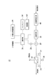
- the structural example of the membrane separation apparatus 18 which comprises at least one part of the purification
- the membrane separation apparatus 18 shown in FIG. 2 mainly comprises a pressure pump 20, a separation membrane 22, a flow meter side means 24, an adjustment means 26, a pressure difference detection means 28, and a heating means 30.
- the water to be treated is separated into the permeate water and the concentrated water by the separation membrane 22 with the circulation water including the discharge water flowing through the circulation flow path 2 (see FIG. 1) as the water to be treated.
- the pressure pump 20 is configured to pressurize the water to be treated and to supply the water to the separation membrane 22, and the flow meter side means 24 is configured to measure the flow rate of the permeated water that has permeated the separation membrane 22.
- separation membrane 22 a reverse osmosis membrane, a microfiltration membrane, an ultrafiltration membrane, a nanofiltration membrane etc. can be used, for example.
- the adjustment means 26 is configured to adjust the pressure of the water to be treated supplied to the separation membrane 22 so that the flow rate of the permeated water measured by the flow meter side means 24 approaches the target flow rate.
- the adjustment means 26 shown in FIG. 2 is configured to adjust the pressure of the water to be supplied to the separation membrane 22 by adjusting the output of the pressure pump 20 using an inverter (not shown) or the like.
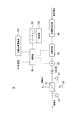
- the adjusting means 26 according to another embodiment is, as shown in FIG. 3, a throttle formed of a valve or a vane capable of adjusting the flow passage area of the flow passage between the pressure pump 20 and the separation membrane 22.
- Means 32 may be provided, and the pressure of the water to be treated supplied to the separation membrane 22 may be adjusted by adjusting the flow passage area by the throttling means 32.
- the pressure difference detection means 28 shown in FIG. 2 is configured to detect the pressure difference ⁇ P before and after the separation membrane (the difference between the pressure of the water to be treated supplied to the separation membrane and the pressure of the permeated water that has permeated the separation membrane).
- the pressure of the water to be treated supplied to the separation membrane 22 and the pressure of the permeated water that has permeated the separation membrane 22 are each detected by a pressure sensor, and the difference between the pressures is calculated.
- the heating means 30 is configured to heat the water to be treated supplied to the separation membrane 22 when the pressure difference ⁇ P detected by the pressure difference detection means 28 exceeds the threshold value ⁇ Pth.
- the heating means 30 heats to-be-processed water, monitoring the measurement result of the thermometer side means 31 which measures the temperature of to-be-processed water.
- a heater configured to heat the water to be treated using electric power as shown in FIG. 2 can be used as shown in FIG. 2 can be used as shown in FIG. 2 can be used as the heating means 30.
- the treated water is configured to be heated by the heating means 30.
- the temperature of the water to be treated is raised by the heating means 30, the viscosity of the water to be treated is lowered, so that the flow rate of the permeated water of the separation membrane 22 under the same pressure condition can be increased. Therefore, as described above, when the water to be treated supplied to the separation membrane 22 is heated by the heating means 30 when the front-rear pressure difference ⁇ P of the separation membrane 22 exceeds the threshold ⁇ Pth, the pressure difference before and after the separation membrane 22 The flow rate of the permeated water of the separation membrane 22 can be increased without excessively increasing the ⁇ P. As a result, it is possible to quickly obtain a permeated water having a desired flow rate and to suppress breakage of the separation membrane.
- the membrane separation device 18 including such heating means 30 constitutes at least a part of the purification means 8 in the circulating water utilization system 1, thereby suppressing breakage of the separation membrane and maintaining the maintainability of the purification means 8 While improving, the water demand amount of the water demand body 3 of the circulating water utilization system 1 can be stably satisfied.
- the adjusting unit 26 be configured to make the pressure of the water to be supplied to the separation membrane 22 constant when the pressure difference ⁇ P exceeds the threshold value ⁇ Pth. Thereby, when the pressure difference ⁇ P before and after the separation membrane 22 detected by the pressure difference detection means 28 exceeds the threshold ⁇ Pth, it is possible to prevent a further increase in the pressure difference, so the separation membrane is broken effectively. Can be suppressed.
- the threshold value ⁇ Pth be set to a smaller value in the case where the use period of the separation membrane 22 exceeds the predetermined period than in the case where the use period is within the predetermined period. For example, it is desirable to set the threshold value ⁇ Pth when the use period of the separation membrane is within one year, to a value smaller than the threshold value ⁇ Pth when the use period of the separation membrane exceeds one year. Since the separation membrane 22 is easily broken due to deterioration due to use, setting the threshold value ⁇ Pth in this way can effectively suppress the break of the separation membrane.
- the membrane separation apparatus 18 shown in FIG. 2 includes an external power supply (such as a power system), a solar power generation apparatus 34 that generates electric power by solar energy, and an external power supply as power supplies for electric power used for the pressurizing pump 20 and the heating unit 30. And a battery 36 that can be charged by the power from the solar power generation device 34, and select an optimal power source from those power sources to supply power to the pressurizing pump 20 and the heating means 30.
- the selection unit 38 configured is provided. It is desirable that the power from the solar power generation device 34 be used directly as much as possible without using the battery 36 from the viewpoint of energy utilization efficiency.
- the selection unit 38 selects which power source to select based on the water production cost (selling price) by the membrane separation device 18 and the remaining amount of the battery 36, or the pressure pump 20 and heating. It may be configured to determine which output of the means 30 to increase or decrease.
- the membrane separation apparatus 18 shown in FIG. 2 has the solar water heater 40 for heating the water to be treated even when the pressure difference ⁇ P detected by the pressure difference detection means 28 does not exceed the threshold ⁇ Pth. There is. Thus, even if the pressure difference ⁇ P detected by the pressure difference detection means 28 does not exceed the threshold ⁇ Pth, the water to be treated is heated by the solar water heater 40 to reduce the viscosity of the water to be treated. The permeated water can be efficiently obtained from the separation membrane 22 by effectively utilizing the sunlight energy contained therein.
- the control unit 100 is configured as a microcomputer including a central processing unit (CPU), a random access memory (RAM), a read only memory (ROM), an I / O interface, and the like.
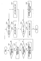
- the solar water heater 40 it is determined whether heating of the water to be treated by the solar water heater 40 is possible. If it is determined in S11 that heating of the water to be treated by the solar water heater 40 is possible, the water surface covered by the solar water heater 40 in S12 regardless of whether the front-rear pressure difference ⁇ P of the separation film 22 exceeds the threshold ⁇ Pth. The treated water is heated, and it is determined in S13 whether the solar power generation device 34 is generating power. If it is determined in S11 that heating of the water to be treated by the solar water heater 40 is not possible, it is determined in S13 whether or not the power generation of the solar power generation device 34 is being performed.
- the generated power of the photovoltaic power generation device 34 is supplied to the heating means 30 in S14 to execute heating of the water to be treated, and the separation membrane in S15. It is determined whether the 22 usage periods exceed a predetermined period (for example, one year). If it is determined in S15 that the use period of the separation membrane 22 does not exceed the predetermined period (for example, 1 year) (within the predetermined period), the threshold ⁇ Pth of the pressure difference across the separation membrane 22 in S16 is set to the first value.
- the threshold value ⁇ Pth of the front-rear pressure difference of the separation membrane 22 is made a second value smaller than the first value in S17.
- the pressure difference ⁇ P detected by the pressure difference detection means 28 exceeds the threshold value ⁇ Pth.
- the pressure of the water to be treated supplied to the separation membrane 22 by the adjustment means 26 is not further increased
- the heating of the water to be treated by the heating means 30 is performed.
- the adjustment means is adjusted so that the flow rate of permeated water approaches the target flow rate in S20.
- the pressure of the water to be treated supplied to the separation membrane 22 is adjusted by 26.
- the pressure difference ⁇ P across the separation membrane 22 exceeds the threshold value ⁇ Pth, the pressure difference ⁇ P across the separation membrane 22 is achieved by heating the water to be treated supplied to the separation membrane 22 by the heating means 30.
- the flow rate of the permeated water of the separation membrane 22 can be increased without excessively increasing the As a result, permeated water having a desired flow rate can be obtained quickly, and breakage of the separation membrane 22 can be suppressed.
- the concentrated water discharged from the separation membrane 22 in FIGS. 2 and 3 may be discharged to the outside of the membrane separation device 18 or may be returned to the upstream side of the pressure pump 20 and pressurized again before the separation membrane. 22 may be supplied to perform membrane separation again.
- At least one embodiment of the present invention can be suitably used in a circulating water utilization system constructed for a specific area separately from the public water supply network.
Landscapes
- Engineering & Computer Science (AREA)
- Water Supply & Treatment (AREA)
- Chemical & Material Sciences (AREA)
- Life Sciences & Earth Sciences (AREA)
- Hydrology & Water Resources (AREA)
- Environmental & Geological Engineering (AREA)
- Organic Chemistry (AREA)
- Nanotechnology (AREA)
- Chemical Kinetics & Catalysis (AREA)
- Separation Using Semi-Permeable Membranes (AREA)
Abstract
被処理水を分離膜22によって透過水と濃縮水とに分離するための膜分離装置であって、被処理水を加圧するための加圧ポンプ20と、加圧ポンプによって加圧された被処理水が供給されるよう構成された分離膜と、分離膜を透過した透過水の流量を計測するための流量計側手段24と、流量計側手段によって計測される透過水の流量を目標流量に近づけるように、分離膜に供給する被処理水の圧力を調節するよう構成された調節手段26と、分離膜の前後の圧力差を検知するための圧力差検知手段28と、圧力差検知手段によって検知した圧力差が閾値を超えた場合に、分離膜に供給される被処理水を加熱するよう構成された加熱手段30と、を有する。 を有する。
Description
本開示は、分離膜を用いて被処理水を透過水と濃縮水とに分離する膜分離装置に関する。
従来、分離膜を用いて被処理水を透過水と濃縮水とに分離する膜分離装置が一般的に用いられている。特許文献1には、海水をろ過したろ過水(被処理水)を逆浸透膜(分離膜)によって更に淡水(透過水)と高濃度塩水(濃縮水)とに膜分離する海水淡水化装置において、逆浸透膜から得られる淡水の流量を目標流量に調節するように、逆浸透膜へ供給するろ過水の圧力を高圧ポンプの出力制御によって調節する構成が開示されている。
特許文献1に記載の海水淡水化装置のように、分離膜に供給する被処理水の圧力を調節することによって分離膜の透過水の流量を目標流量に近づける構成においては、圧力調節に対する透過水流量の応答性が比較的高いというメリットがあるものの、透過水流量を多くするために分離膜の前後の圧力差(分離膜に供給される被処理水の圧力と分離膜を透過した透過水の圧力との差)を過度に大きくすると、分離膜が破れてしまい、被処理水の不純物を十分に除去することができなくなることがあった。
本発明の少なくとも一つの実施形態は、上述したような従来の課題に鑑みなされたものであって、その目的とするところは、分離膜の前後の圧力差を過度に大きくすることなく分離膜の透過水の流量を増加させることで、所望の流量の透過水を速やかに得るとともに分離膜の破れを抑制することができる膜分離装置を提供することにある。
(1)本発明の幾つかの実施形態に係る膜分離装置は、
被処理水を分離膜によって透過水と濃縮水とに分離するための膜分離装置であって、
被処理水を加圧するための加圧ポンプと、
前記加圧ポンプによって加圧された前記被処理水が供給されるよう構成された分離膜と、
前記分離膜を透過した透過水の流量を計測するための流量計側手段と、
前記流量計側手段によって計測される前記透過水の流量を目標流量に近づけるように、前記分離膜に供給する前記被処理水の圧力を調節するよう構成された調節手段と、
前記分離膜の前後の圧力差を検知するための圧力差検知手段と、
前記圧力差検知手段によって検知した前記圧力差が閾値を超えた場合に、前記分離膜に供給される前記被処理水を加熱するよう構成された加熱手段と、
を有する。
被処理水を分離膜によって透過水と濃縮水とに分離するための膜分離装置であって、
被処理水を加圧するための加圧ポンプと、
前記加圧ポンプによって加圧された前記被処理水が供給されるよう構成された分離膜と、
前記分離膜を透過した透過水の流量を計測するための流量計側手段と、
前記流量計側手段によって計測される前記透過水の流量を目標流量に近づけるように、前記分離膜に供給する前記被処理水の圧力を調節するよう構成された調節手段と、
前記分離膜の前後の圧力差を検知するための圧力差検知手段と、
前記圧力差検知手段によって検知した前記圧力差が閾値を超えた場合に、前記分離膜に供給される前記被処理水を加熱するよう構成された加熱手段と、
を有する。
分離膜に供給する被処理水の圧力を調節することによって分離膜の透過水の流量を目標流量に近づける構成においては、圧力調節に対する透過水流量の応答性が比較的高いというメリットがあるものの、透過水流量を多くするために分離膜の前後の圧力差を過度に大きくすると、分離膜が破れてしまい、被処理水の不純物を十分に除去することができなくなることがあった。
そこで、上記(1)に記載の膜分離装置では、圧力差検知手段によって検知した分離膜の前後圧力差が閾値を超えた場合に、分離膜に供給される被処理水を加熱手段によって加熱するよう構成されている。
加熱手段によって被処理水の温度を上げれば、被処理水の粘度が低下するため、同一圧力条件下での分離膜の透過水流量を増加させることができる。したがって上述のように、分離膜の前後圧力差が閾値を超えた場合に、加熱手段によって分離膜に供給される被処理水を加熱手段によって加熱すれば、分離膜の前後の圧力差を過度に大きくすることなく分離膜の透過水の流量を増加させることができる。これにより、所望の流量の透過水を速やかに得るとともに分離膜の破れを抑制することができる。
なお、ここでの「分離膜」は、少なくとも、逆浸透膜(RO膜)、精密ろ過膜(MF膜)、限外ろ過膜(UF膜)、ナノろ過膜(NF膜)を含む意味で用いている。
そこで、上記(1)に記載の膜分離装置では、圧力差検知手段によって検知した分離膜の前後圧力差が閾値を超えた場合に、分離膜に供給される被処理水を加熱手段によって加熱するよう構成されている。
加熱手段によって被処理水の温度を上げれば、被処理水の粘度が低下するため、同一圧力条件下での分離膜の透過水流量を増加させることができる。したがって上述のように、分離膜の前後圧力差が閾値を超えた場合に、加熱手段によって分離膜に供給される被処理水を加熱手段によって加熱すれば、分離膜の前後の圧力差を過度に大きくすることなく分離膜の透過水の流量を増加させることができる。これにより、所望の流量の透過水を速やかに得るとともに分離膜の破れを抑制することができる。
なお、ここでの「分離膜」は、少なくとも、逆浸透膜(RO膜)、精密ろ過膜(MF膜)、限外ろ過膜(UF膜)、ナノろ過膜(NF膜)を含む意味で用いている。
(2)幾つかの実施形態では、上記(1)に記載の膜分離装置において、
前記閾値は、前記分離膜の使用期間が所定期間以内の場合よりも、前記所定期間を超えた場合の方が、小さい値に設定される。
前記閾値は、前記分離膜の使用期間が所定期間以内の場合よりも、前記所定期間を超えた場合の方が、小さい値に設定される。
分離膜は使用に伴う劣化によって破れやすくなるため、上記(2)に記載のように、分離膜の使用期間が所定期間以内の場合よりも、所定期間を超えた場合の方が閾値を小さい値に設定することで、分離膜の破れを効果的に抑制することができる。
(3)幾つかの実施形態では、上記(1)又は(2)に記載の膜分離装置において、
前記調節手段は、前記圧力差が閾値を超えた場合に、前記分離膜に供給する前記被処理水の圧力を一定にする。
前記調節手段は、前記圧力差が閾値を超えた場合に、前記分離膜に供給する前記被処理水の圧力を一定にする。
これにより、圧力差検知手段によって検知された分離膜の前後の圧力差が閾値を超えた場合に、それ以上の圧力差の上昇を防ぐことができるため、分離膜の破れを効果的に抑制することができる。
(4)幾つかの実施形態では、上記(1)~(3)のいずれか1項に記載の膜分離装置において、
前記調節手段は、前記加圧ポンプの出力を調節することにより前記分離膜に供給する前記被処理水の圧力を調節するよう構成される。
前記調節手段は、前記加圧ポンプの出力を調節することにより前記分離膜に供給する前記被処理水の圧力を調節するよう構成される。
上記(4)に記載のように分離膜に供給する被処理水の圧力を加圧ポンプの出力調節によって調節する場合、バルブやベーン等の絞り手段によって該圧力を調節する場合と比較して、該絞り手段による圧力損失が無い分、膜分離装置の消費エネルギーを低減することができる。
(5)幾つかの実施形態では、上記(1)~(3)のいずれか1項に記載の膜分離装置において、
前記調節手段は、前記加圧ポンプと前記分離膜との間の流路に該流路の流路面積を調節可能な絞り手段を備え、前記絞り手段によって前記流路面積を調節することにより前記分離膜に供給する前記被処理水の圧力を調節するよう構成される。
前記調節手段は、前記加圧ポンプと前記分離膜との間の流路に該流路の流路面積を調節可能な絞り手段を備え、前記絞り手段によって前記流路面積を調節することにより前記分離膜に供給する前記被処理水の圧力を調節するよう構成される。
上記(5)に記載のように分離膜に供給する被処理水の圧力を絞り手段によって調節する場合、加圧ポンプの出力調節によって該圧力を調節する場合と比較して、加圧ポンプの出力調節に用いるインバータ等が不要なため、電気設備の簡素化を図ることができる。
(6)幾つかの実施形態では、上記(1)~(5)のいずれか1項に記載の膜分離装置において、
太陽光エネルギーによって発電する太陽光発電装置を更に備え、
前記加熱手段は、前記圧力差検知手段によって検知した前記圧力差が前記閾値を超えていない場合であっても、前記太陽光発電装置の発電電力を用いて前記被処理水の加熱を行うよう構成される。
太陽光エネルギーによって発電する太陽光発電装置を更に備え、
前記加熱手段は、前記圧力差検知手段によって検知した前記圧力差が前記閾値を超えていない場合であっても、前記太陽光発電装置の発電電力を用いて前記被処理水の加熱を行うよう構成される。
太陽光発電装置からの電力は、エネルギー利用効率の観点から、バッテリ等を介さずになるべく直接使用した方が望ましい。従って、上記(6)に記載の膜分離装置では、圧力差検知手段によって検知した圧力差が閾値を超えていない場合であっても、太陽光発電装置の発電出力を用いて被処理水の加熱を行うよう構成することで、被処理水の粘度を低下させ、膜分離装置全体でエネルギーを効率的に利用することができる。
(7)幾つかの実施形態では、上記(1)~(6)のいずれか1項に記載の膜分離装置において、
前記圧力差検知手段によって検知した前記圧力差が前記閾値を超えていない場合であっても、前記被処理水を加熱する太陽熱温水器を更に有する。
上記(7)に記載の膜分離装置によれば、圧力差検知手段によって検知した圧力差が閾値を超えていない場合であっても太陽熱温水器によって被処理水を加熱して被処理水の粘度を低下させることで、日中の太陽光エネルギーを有効活用して分離膜から透過水を効率的に得ることができる。
前記圧力差検知手段によって検知した前記圧力差が前記閾値を超えていない場合であっても、前記被処理水を加熱する太陽熱温水器を更に有する。
上記(7)に記載の膜分離装置によれば、圧力差検知手段によって検知した圧力差が閾値を超えていない場合であっても太陽熱温水器によって被処理水を加熱して被処理水の粘度を低下させることで、日中の太陽光エネルギーを有効活用して分離膜から透過水を効率的に得ることができる。
(8)幾つかの実施形態に係る循環水利用システムは、
循環水が流れる循環流路と、
前記循環流路を流れる循環水を使用する、住居、テナント、及び事務所の内の少なくとも一種からなる小口水需要体が複数集まって構成される水需要体、から排出される排出水を前記循環流路へ排出する排出流路と、
前記循環流路を流れる前記排出水を含む循環水を浄化する浄化手段と、
前記浄化手段で浄化された循環水を前記水需要体に供給する供給流路と、
を有し、
上記(1)~(7)のいずれか1項に記載の膜分離装置が、前記浄化手段の少なくとも一部を構成する。
上記(8)に記載の循環水利用システムによれば、分離膜の前後圧力差が閾値を超えた場合に、加熱手段によって分離膜に供給される被処理水を加熱手段によって加熱するので、分離膜の前後の圧力差を過度に大きくすることなく分離膜の透過水の流量を増加させることができる。これにより、所望の流量の透過水を速やかに得るとともに分離膜の破れを抑制することができる。すなわち、分離膜の破れを抑制しつつ、上記循環水利用システムの水需要体の水需要量を、該分離膜によって浄化された循環水によって満たすことができる。
循環水が流れる循環流路と、
前記循環流路を流れる循環水を使用する、住居、テナント、及び事務所の内の少なくとも一種からなる小口水需要体が複数集まって構成される水需要体、から排出される排出水を前記循環流路へ排出する排出流路と、
前記循環流路を流れる前記排出水を含む循環水を浄化する浄化手段と、
前記浄化手段で浄化された循環水を前記水需要体に供給する供給流路と、
を有し、
上記(1)~(7)のいずれか1項に記載の膜分離装置が、前記浄化手段の少なくとも一部を構成する。
上記(8)に記載の循環水利用システムによれば、分離膜の前後圧力差が閾値を超えた場合に、加熱手段によって分離膜に供給される被処理水を加熱手段によって加熱するので、分離膜の前後の圧力差を過度に大きくすることなく分離膜の透過水の流量を増加させることができる。これにより、所望の流量の透過水を速やかに得るとともに分離膜の破れを抑制することができる。すなわち、分離膜の破れを抑制しつつ、上記循環水利用システムの水需要体の水需要量を、該分離膜によって浄化された循環水によって満たすことができる。
本発明の少なくとも一つの実施形態によれば、分離膜の前後の圧力差を過度に大きくすることなく分離膜の透過水の流量を増加させることで、所望の流量の透過水を速やかに得るとともに分離膜の破れを抑制することができる膜分離装置を提供することができる。
以下、本発明の実施形態について、図面に基づいてより詳細に説明する。
ただし、本発明の範囲は以下の実施形態に限定されるものではない。以下の実施形態に記載されている構成部品の寸法、材質、形状、その相対配置などは、本発明の範囲をそれにのみ限定する趣旨ではなく、単なる説明例に過ぎない。
ただし、本発明の範囲は以下の実施形態に限定されるものではない。以下の実施形態に記載されている構成部品の寸法、材質、形状、その相対配置などは、本発明の範囲をそれにのみ限定する趣旨ではなく、単なる説明例に過ぎない。
図1は、本発明の少なくとも一実施形態にかかる循環水利用システムを示した全体模式図である。
循環水利用システム1は、公共の上水道網とは別に、特定の地域を対象として構築されるシステムである。本システムの対象となる人口規模としては、おおよそ5,000~20,000人を想定している。対象地域としては、住居の集合体であるマンション、事務所の集合体であるオフィスビル、テナントの集合体である商業施設、及びこれらが混在する複合施設などである。
循環水利用システム1は、公共の上水道網とは別に、特定の地域を対象として構築されるシステムである。本システムの対象となる人口規模としては、おおよそ5,000~20,000人を想定している。対象地域としては、住居の集合体であるマンション、事務所の集合体であるオフィスビル、テナントの集合体である商業施設、及びこれらが混在する複合施設などである。
図1に示したように、循環水利用システム1は、循環流路2、水需要体3、排出流路4、供給流路6、浄化手段8(浄化装置)、飲用水生成手段12、飲用水供給手段14、などからなる。
循環流路2は、水道管が閉ループ状に配管されてなる管網として構成される。循環流路2を流れる循環水の原水は、公共の上水道から供給される水道水に限定されず、井戸水、河川から取水した水、海水を淡水化した水、雨水等であってもよい。また、循環水が不足する場合には、これらの原水を外部から補給水として循環流路2に取り入れるように構成してもよい。
水需要体3は、循環流路2を流れる循環水を生活用水として利用する主体である。水需要体3は、住居3a、テナント3b、及び事務所3cの内の少なくとも一種からなる小口水需要体が複数集まって構成される。住居3aとは、1世帯が生活するマンションの一部屋や戸建て家屋などを指す。テナント3bは、商業施設の一区画において一般顧客に対してサービスを提供する店舗などを指す。業種としては、例えば、服飾店、雑貨店、ドラッグストア、酒屋、等々の小売業や、レストラン、カフェ、寿司屋、居酒屋、等々の飲食業などを含む。事務所3cは、オフィスビルの一部分などにおいて、そこで働く勤務者が一定の目的のために事務を行う場所を指す。
住居3aにおける生活用水の用途としては、例えばシャワーや風呂、洗濯、食器の洗浄、手洗いや洗顔、トイレ、等々が挙げられる。テナント3bにおける生活用水の用途としては、洗浄やトイレ等が挙げられる。また業種によって水需要量が大きく異なっており、例えば飲食店は小売業と比べてはるかに大量の生活用水を利用する。事務所3cにおける生活用水の用途は主にトイレである。
住居3aにおける生活用水の用途としては、例えばシャワーや風呂、洗濯、食器の洗浄、手洗いや洗顔、トイレ、等々が挙げられる。テナント3bにおける生活用水の用途としては、洗浄やトイレ等が挙げられる。また業種によって水需要量が大きく異なっており、例えば飲食店は小売業と比べてはるかに大量の生活用水を利用する。事務所3cにおける生活用水の用途は主にトイレである。
また、水需要体3には、上述した循環水とは別に、飲用水が供給される。この飲用水は、公共の上水道網から導水した水道水を更に浄化することで生成され、市販のミネラルウォーターと同等の品質を有するものである。このような仕組みは、循環水を飲用することに抵抗を感じる人の不安感を解消させることができるとともに、本循環水利用システム1を普及させる際のセールスポイントとなることを期待してのものである。
水道水は、水道水導水管16を介して、公共の上水道網から飲用水生成手段12に導水される。飲用水生成手段12は、導水した水道水を浄化して水需要体3のための飲用水を生成する。
飲用水生成手段12で生成された飲用水は、飲用水供給手段14によって小口水需要体の各々に供給される。飲用水供給手段14は、飲用水送水管14a、貯留タンク14b、及び飲用水配管14cなどからなる。飲用水生成手段12で生成された飲用水は、飲用水送水管14aを介して貯留タンク14bに送水され、貯留タンク14bにて一旦貯留される。そして、貯留タンク14bに貯留されている飲用水は、飲用水配管14cを介して、上述した住居3a、テナント3b、及び事務所3cからなる小口水需要体の各々に供給される。なお、循環水利用システム1における飲用水の原水は、水道水には限定されず、例えば井戸水や河川から取水した水、海水を淡水化した水などであってもよい。
排出流路4は、水需要体3から排出される排出水を循環流路2へ排水するための流路である。この排出流路4から排水される排出水には、水需要体3が生活用水として利用した循環水の他に、飲用水やその他のシステム外由来の水も含まれている。供給流路6は、後述する浄化手段8で浄化された循環水を生活用水として水需要体3に供給するための流路である。排出流路4及び供給流路6は共に管路から構成される。
また、本循環水利用システム1において、上記循環流路2は、公共の下水道網には接続されていない。後述するように、排出水の浄化過程で発生する汚泥ケーキ等の余剰汚泥はシステム外に搬出されるが、それ以外の排出水は100%再利用される。すなわち、本循環水利用システム1は、システム内で循環的に水供給と水処理とが行われ、システム外には下水を排出しない完全循環型の循環水利用システムとなっている。
なお、排出流路4及び供給流路6には、排出水が循環流路2に排水されるように、又は循環水が水需要体3に供給されるように、ポンプやバルブなどの機器類が地形条件等に応じて上述した以外に適宜設置されてもよい。
なお、排出流路4及び供給流路6には、排出水が循環流路2に排水されるように、又は循環水が水需要体3に供給されるように、ポンプやバルブなどの機器類が地形条件等に応じて上述した以外に適宜設置されてもよい。
浄化手段8は、循環流路2を流れる排出水を含む循環水を浄化する手段であり、膜分離装置18を有している。図2に、浄化手段8の少なくとも一部を構成する膜分離装置18の構成例を示す。
図2に示す膜分離装置18は、加圧ポンプ20と、分離膜22と、流量計側手段24と、調節手段26と、圧力差検知手段28と、加熱手段30と、を主に備えており、循環流路2(図1参照)を流れる排出水を含む循環水を被処理水として、該被処理水を分離膜22によって透過水と濃縮水とに分離するよう構成されている。
加圧ポンプ20は、被処理水を加圧して分離膜22に供給するよう構成され、流量計側手段24は、分離膜22を透過した透過水の流量を計測するよう構成されている。分離膜22としては、例えば逆浸透膜、精密ろ過膜、限外ろ過膜、ナノろ過膜等を用いることができる。
調節手段26は、流量計側手段24によって計測される透過水の流量を目標流量に近づけるように、分離膜22に供給する被処理水の圧力を調節するよう構成される。
図2に示す調節手段26は、加圧ポンプ20の出力を不図示のインバータ等を用いて調節することにより分離膜22に供給する被処理水の圧力を調節するよう構成される。
他の実施形態に係る調節手段26は、図3に示すように、加圧ポンプ20と分離膜22との間の流路に該流路の流路面積を調節可能なバルブ又はベーンからなる絞り手段32を備え、絞り手段32によって流路面積を調節することにより分離膜22に供給する被処理水の圧力を調節するよう構成してもよい。
図2に示す調節手段26は、加圧ポンプ20の出力を不図示のインバータ等を用いて調節することにより分離膜22に供給する被処理水の圧力を調節するよう構成される。
他の実施形態に係る調節手段26は、図3に示すように、加圧ポンプ20と分離膜22との間の流路に該流路の流路面積を調節可能なバルブ又はベーンからなる絞り手段32を備え、絞り手段32によって流路面積を調節することにより分離膜22に供給する被処理水の圧力を調節するよう構成してもよい。
図2に示す圧力差検知手段28は、分離膜の前後の圧力差ΔP(分離膜に供給される被処理水の圧力と分離膜を透過した透過水の圧力との差)を検知するよう構成されており、幾つかの実施形態では、分離膜22に供給される被処理水の圧力と分離膜22を透過した透過水の圧力とをそれぞれ圧力センサで検知し、それらの圧力の差を算出するよう構成される。
加熱手段30は、圧力差検知手段28によって検知した圧力差ΔPが閾値ΔPthを超えた場合に、分離膜22に供給される被処理水を加熱するよう構成されている。加熱手段30は、被処理水の温度を計測する温度計側手段31の計測結果をモニタしながら被処理水の加熱を行う。幾つかの実施形態では、加熱手段30として、図2に示すように電力を用いて被処理水を加熱するよう構成されたヒーターを用いることができる。
分離膜22に供給する被処理水の圧力を調節することによって分離膜22の透過水の流量を目標流量に近づける構成においては、圧力調節に対する透過水流量の応答性が比較的高いというメリットがあるものの、透過水流量を多くするために分離膜22の前後の圧力差ΔPを過度に大きくすると、分離膜22が破れてしまい、被処理水の不純物を十分に除去することができなくなることがあった。
そこで、図2に示す膜分離装置18においては、上述のように、圧力差検知手段28によって検知した分離膜22の前後圧力差ΔPが閾値を超えた場合に、分離膜22に供給される被処理水を加熱手段30によって加熱するよう構成されている。
加熱手段30によって被処理水の温度を上げれば、被処理水の粘度が低下するため、同一圧力条件下での分離膜22の透過水流量を増加させることができる。したがって上述のように、分離膜22の前後圧力差ΔPが閾値ΔPthを超えた場合に、分離膜22に供給される被処理水を加熱手段30によって加熱すれば、分離膜22の前後の圧力差ΔPを過度に大きくすることなく分離膜22の透過水の流量を増加させることができる。これにより、所望の流量の透過水を速やかに得るとともに分離膜の破れを抑制することができる。また、このような加熱手段30を含む膜分離装置18が上記循環水利用システム1における浄化手段8の少なくとも一部を構成することで、分離膜の破れを抑制して浄化手段8のメンテナンス性を向上しつつ、循環水利用システム1の水需要体3の水需要量を、安定的に満たすことができる。
なお調節手段26は、圧力差ΔPが閾値ΔPthを超えた場合に、分離膜22に供給する被処理水の圧力を一定にするよう構成することが望ましい。これにより、圧力差検知手段28によって検知された分離膜22の前後の圧力差ΔPが閾値ΔPthを超えた場合に、それ以上の圧力差の上昇を防ぐことができるため、分離膜の破れを効果的に抑制することができる。
また、閾値ΔPthは、分離膜22の使用期間が所定期間以内の場合よりも、所定期間を超えた場合の方が、小さい値に設定されていることが望ましい。例えば、分離膜の使用期間が1年以内の時の閾値ΔPthを、分離膜の使用期間が1年を超えた時の閾値ΔPthよりも小さい値に設定することが望ましい。分離膜22は使用に伴う劣化によって破れやすくなるため、閾値ΔPthをこのように設定することで、分離膜の破れを効果的に抑制することができる。
図2に示す膜分離装置18は、加圧ポンプ20と加熱手段30とに用いる電力の電源として、外部電源(電力系統等)と、太陽光エネルギーによって発電する太陽光発電装置34と、外部電源及び太陽光発電装置34からの電力によって充電可能なバッテリ36とを更に備えており、また、それらの電源から最適な電源を選択して加圧ポンプ20と加熱手段30とに電力を供給するよう構成された選択部38を備えている。この太陽光発電装置34からの電力は、エネルギー利用効率の観点から、なるべくバッテリ36を介さずになるべく直接使用した方が望ましい。従って、圧力差検知手段28によって検知した圧力差ΔPが閾値ΔPthを超えていない場合であっても、太陽光発電装置34の発電出力を用いて加熱手段30による被処理水の加熱を行うことで、被処理水の粘度を低下させ、膜分離装置18全体でエネルギーを効率的に利用することができる。なお、幾つかの実施形態では、選択部38は、膜分離装置18による造水コスト(売値)及びバッテリ36の残量を加味して、いずれの電源を選択するか、加圧ポンプ20と加熱手段30のいずれの出力を増加あるいは減少させるかを判断するよう構成してもよい。
また、図2に示す膜分離装置18は、圧力差検知手段28によって検知した圧力差ΔPが閾値ΔPthを超えていない場合であっても、被処理水を加熱する太陽熱温水器40を有している。これにより、圧力差検知手段28によって検知した圧力差ΔPが閾値ΔPthを超えていない場合であっても太陽熱温水器40によって被処理水を加熱して被処理水の粘度を低下させることで、日中の太陽光エネルギーを有効活用して分離膜22から透過水を効率的に得ることができる。
上述した膜分離装置18の主な動作フローの例を図4に示す。以下の動作フローは、膜分離装置18が備える制御部100(図1参照)によって実行される。制御部100は、中央処理装置(CPU)、ランダムアクセスメモリ(RAM)、リードオンリメモリ(ROM)、およびI/Oインターフェイスなどからなるマイクロコンピュータとして構成されている。
まず、S11で太陽熱温水器40による被処理水の加熱が可能であるか否かを判断する。S11で太陽熱温水器40による被処理水の加熱が可能であると判断した場合、分離膜22の前後圧力差ΔPが閾値ΔPthを超えているか否かに関わらず、S12で太陽熱温水器40による被処理水の加熱を行い、S13で太陽光発電装置34の発電が行われているか否かを判断する。S11で太陽熱温水器40による被処理水の加熱が可能でないと判断した場合、S13で太陽光発電装置34の発電が行われているか否かを判断する。S13で太陽光発電装置34の発電が行われていると判断した場合、S14で太陽光発電装置34の発電電力を加熱手段30に供給して被処理水の加熱を実行し、S15で分離膜22の使用期間が所定期間(例えば1年)を超えているかどうかを判断する。S15で分離膜22の使用期間が所定期間(例えば1年)を超えていない(所定期間以内である)と判断した場合、S16で分離膜22の前後圧力差の閾値ΔPthを第1の値に設定する。S15で分離膜22の使用期間が所定期間(例えば1年)を超えていると判断した場合、S17で分離膜22の前後圧力差の閾値ΔPthを第1の値よりも小さい第2の値に設定する。
次に、S18で、圧力差検知手段28によって検知した圧力差ΔPが閾値ΔPthを超えているか否かを判断する。S18で、圧力差検知手段28によって検知した圧力差ΔPが閾値ΔPthを超えていると判断した場合、S19で、調節手段26によって分離膜22に供給する被処理水の圧力がそれ以上上昇しないように一定にするとともに、加熱手段30による被処理水の加熱を実行する。S18で、圧力差検知手段28によって検知した圧力差ΔPが閾値ΔPthを超えていない(閾値ΔPth以下である)と判断した場合、S20で、透過水の流量が目標流量に近づくように、調節手段26によって分離膜22に供給する被処理水の圧力を調節する。
このように、分離膜22の前後圧力差ΔPが閾値ΔPthを超えた場合に、分離膜22に供給される被処理水を加熱手段30によって加熱することで、分離膜22の前後の圧力差ΔPを過度に大きくすることなく分離膜22の透過水の流量を増加させることができる。これにより、所望の流量の透過水を速やかに得るとともに、分離膜22の破れを抑制することができる。
なお、図2及び図3において分離膜22から排出された濃縮水は、膜分離装置18の外に排出してもよいし、加圧ポンプ20の上流側に戻して再度加圧した後に分離膜22に供給して再び膜分離を行ってもよい。
なお、図2及び図3において分離膜22から排出された濃縮水は、膜分離装置18の外に排出してもよいし、加圧ポンプ20の上流側に戻して再度加圧した後に分離膜22に供給して再び膜分離を行ってもよい。
以上、本発明の好ましい形態について説明したが、本発明は上記の形態に限定されるものではない。例えば上述した実施形態を組み合わせても良く、本発明の目的を逸脱しない範囲での種々の変更が可能である。
本発明の少なくとも一実施形態は、公共の上水道網とは別に、特定の地域を対象として構築される循環水利用システムにおいて好適に用いることが出来る。
1 循環水利用システム
2 循環流路
3 水需要体
3a 住居
3b テナント
3c 事務所
4 排出流路
6 供給流路
8 浄化手段
12 飲用水生成手段
14 飲用水供給手段
14a 飲用水送水管
14b 貯留タンク
14c 飲用水配管
16 水道水導水管
18 膜分離装置
20 加圧ポンプ
22 分離膜
24 流量計側手段
26 調節手段
28 圧力差検知手段
30 加熱手段
31 温度計側手段
32 絞り手段
34 太陽光発電装置
36 バッテリ
38 選択部
40 太陽熱温水器
100 制御部
2 循環流路
3 水需要体
3a 住居
3b テナント
3c 事務所
4 排出流路
6 供給流路
8 浄化手段
12 飲用水生成手段
14 飲用水供給手段
14a 飲用水送水管
14b 貯留タンク
14c 飲用水配管
16 水道水導水管
18 膜分離装置
20 加圧ポンプ
22 分離膜
24 流量計側手段
26 調節手段
28 圧力差検知手段
30 加熱手段
31 温度計側手段
32 絞り手段
34 太陽光発電装置
36 バッテリ
38 選択部
40 太陽熱温水器
100 制御部
Claims (8)
- 被処理水を分離膜によって透過水と濃縮水とに分離するための膜分離装置であって、
被処理水を加圧するための加圧ポンプと、
前記加圧ポンプによって加圧された前記被処理水が供給されるよう構成された分離膜と、
前記分離膜を透過した透過水の流量を計測するための流量計側手段と、
前記流量計側手段によって計測された前記透過水の流量を目標流量に近づけるように、前記分離膜に供給する前記被処理水の圧力を調節するよう構成された調節手段と、
前記分離膜の前後の圧力差を検知するための圧力差検知手段と、
前記圧力差検知手段によって検知した前記圧力差が閾値を超えた場合に、前記分離膜に供給される前記被処理水を加熱するよう構成された加熱手段と、
を有する膜分離装置。 - 前記閾値は、前記分離膜の使用期間が所定期間以内の場合よりも、前記所定期間を超えた場合の方が、小さい値に設定される請求項1に記載の膜分離装置。
- 前記調節手段は、前記圧力差が前記閾値を超えた場合に、前記分離膜に供給する前記被処理水の圧力を一定にするよう構成される請求項1又は2に記載の膜分離装置。
- 前記調節手段は、前記加圧ポンプの出力を調節することにより前記分離膜に供給する前記被処理水の圧力を調節するよう構成された請求項1~3の何れか1項に記載の膜分離装置。
- 前記調節手段は、前記加圧ポンプと前記分離膜との間の流路に該流路の流路面積を調節可能な絞り手段を備え、前記絞り手段によって前記流路面積を調節することにより前記分離膜に供給する前記被処理水の圧力を調節するよう構成された請求項1~3の何れか1項に記載の膜分離装置。
- 太陽光エネルギーによって発電する太陽光発電装置を更に備え、
前記加熱手段は、前記圧力差検知手段によって検知した前記圧力差が前記閾値を超えていない場合であっても、前記太陽光発電装置の発電電力を用いて前記被処理水の加熱を行うよう構成された請求項1~5のいずれか1項に記載の膜分離装置。 - 前記圧力差検知手段によって検知した前記圧力差が前記閾値を超えていない場合であっても、前記被処理水を加熱する太陽熱温水器を更に有する請求項1~6のいずれか1項に記載の膜分離装置。
- 循環水が流れる循環流路と、
前記循環流路を流れる循環水を使用する、住居、テナント、及び事務所の内の少なくとも一種からなる小口水需要体が複数集まって構成される水需要体、から排出される排出水を前記循環流路へ排出する排出流路と、
前記循環流路を流れる前記排出水を含む循環水を浄化する浄化手段と、
前記浄化手段で浄化された循環水を前記水需要体に供給する供給流路と、
を有し、
請求項1~7のいずれか1項に記載の膜分離装置が、前記浄化手段の少なくとも一部を構成する循環水利用システム。
Applications Claiming Priority (2)
| Application Number | Priority Date | Filing Date | Title |
|---|---|---|---|
| JP2013251630A JP5558622B1 (ja) | 2013-12-05 | 2013-12-05 | 循環水利用システム |
| JP2013-251630 | 2013-12-05 |
Publications (1)
| Publication Number | Publication Date |
|---|---|
| WO2015083773A1 true WO2015083773A1 (ja) | 2015-06-11 |
Family
ID=51416945
Family Applications (1)
| Application Number | Title | Priority Date | Filing Date |
|---|---|---|---|
| PCT/JP2014/082078 Ceased WO2015083773A1 (ja) | 2013-12-05 | 2014-12-04 | 膜分離装置、循環水利用システム |
Country Status (2)
| Country | Link |
|---|---|
| JP (1) | JP5558622B1 (ja) |
| WO (1) | WO2015083773A1 (ja) |
Citations (7)
| Publication number | Priority date | Publication date | Assignee | Title |
|---|---|---|---|---|
| JPH06277455A (ja) * | 1993-03-29 | 1994-10-04 | Mitsubishi Heavy Ind Ltd | 限外ろ過膜モジュールの運転方法 |
| JPH0768257A (ja) * | 1993-09-02 | 1995-03-14 | Takenaka Komuten Co Ltd | 淡水製造装置 |
| JPH1033953A (ja) * | 1996-07-29 | 1998-02-10 | Asahi Chem Ind Co Ltd | 濾過処理方法及び濾過装置 |
| JP2001170458A (ja) * | 1999-12-15 | 2001-06-26 | Meidensha Corp | 膜浄水処理における膜破断とファウリングの検出方法 |
| JP2004249174A (ja) * | 2003-02-18 | 2004-09-09 | Toshiba Corp | ろ過装置およびその運転方法 |
| JP2007185648A (ja) * | 2005-09-01 | 2007-07-26 | Toray Ind Inc | 膜ろ過装置の運転条件の決定方法、およびそれを用いた膜ろ過装置の運転方法、膜ろ過装置 |
| JP2013188710A (ja) * | 2012-03-14 | 2013-09-26 | Toshiba Corp | 膜ろ過装置及び造水装置並びに膜ろ過装置の洗浄方法 |
Family Cites Families (8)
| Publication number | Priority date | Publication date | Assignee | Title |
|---|---|---|---|---|
| JPH06226059A (ja) * | 1993-01-29 | 1994-08-16 | Kuraray Co Ltd | 濾過装置 |
| CA2396853A1 (en) * | 2000-01-11 | 2001-07-19 | Nephros, Inc. | Thermally enhanced dialysis/diafiltration system |
| JP2006305499A (ja) * | 2005-04-28 | 2006-11-09 | Miura Co Ltd | 膜濾過システムの運転方法 |
| DK2641652T3 (en) * | 2007-09-12 | 2019-04-29 | Danisco Us Inc | FILTERING WITH INTERNAL POLLUTION CONTROL |
| JP4832393B2 (ja) * | 2007-09-20 | 2011-12-07 | 月島環境エンジニアリング株式会社 | 膜を用いたポリグリセリンの分離方法及び分離装置 |
| JP2010253355A (ja) * | 2009-04-22 | 2010-11-11 | Sumitomo Electric Ind Ltd | 膜分離活性汚泥処理装置 |
| JP2010120015A (ja) * | 2010-02-02 | 2010-06-03 | Miura Co Ltd | 膜濾過方法 |
| JP5367758B2 (ja) * | 2011-05-02 | 2013-12-11 | 株式会社東芝 | 温度応答性膜を用いた膜ろ過システム |
-
2013
- 2013-12-05 JP JP2013251630A patent/JP5558622B1/ja active Active
-
2014
- 2014-12-04 WO PCT/JP2014/082078 patent/WO2015083773A1/ja not_active Ceased
Patent Citations (7)
| Publication number | Priority date | Publication date | Assignee | Title |
|---|---|---|---|---|
| JPH06277455A (ja) * | 1993-03-29 | 1994-10-04 | Mitsubishi Heavy Ind Ltd | 限外ろ過膜モジュールの運転方法 |
| JPH0768257A (ja) * | 1993-09-02 | 1995-03-14 | Takenaka Komuten Co Ltd | 淡水製造装置 |
| JPH1033953A (ja) * | 1996-07-29 | 1998-02-10 | Asahi Chem Ind Co Ltd | 濾過処理方法及び濾過装置 |
| JP2001170458A (ja) * | 1999-12-15 | 2001-06-26 | Meidensha Corp | 膜浄水処理における膜破断とファウリングの検出方法 |
| JP2004249174A (ja) * | 2003-02-18 | 2004-09-09 | Toshiba Corp | ろ過装置およびその運転方法 |
| JP2007185648A (ja) * | 2005-09-01 | 2007-07-26 | Toray Ind Inc | 膜ろ過装置の運転条件の決定方法、およびそれを用いた膜ろ過装置の運転方法、膜ろ過装置 |
| JP2013188710A (ja) * | 2012-03-14 | 2013-09-26 | Toshiba Corp | 膜ろ過装置及び造水装置並びに膜ろ過装置の洗浄方法 |
Also Published As
| Publication number | Publication date |
|---|---|
| JP2015107468A (ja) | 2015-06-11 |
| JP5558622B1 (ja) | 2014-07-23 |
Similar Documents
| Publication | Publication Date | Title |
|---|---|---|
| JP5606615B1 (ja) | 膜分離装置、循環水利用システム | |
| Khanzada et al. | Performance evaluation of reverse osmosis (RO) pre-treatment technologies for in-land brackish water treatment | |
| US9045359B2 (en) | Reverse osmosis negative-ion water dispenser | |
| JP7536042B2 (ja) | 浄水装置および浄水装置の制御方法 | |
| Zhang et al. | Estimation of water footprint in seawater desalination with reverse osmosis process | |
| Richards et al. | Photovoltaic-powered desalination system for remote Australian communities | |
| JP5563142B1 (ja) | 循環水利用システム | |
| US20120031844A1 (en) | Flow-switch-controlled, zero waste reverse osmosis water treatment system | |
| CN107152057B (zh) | 智能直饮水给水售水系统及其供水方法 | |
| WO2015083784A1 (ja) | 循環水利用システム | |
| CN101765565B (zh) | 具有温度控制的反渗透装置 | |
| WO2015083774A1 (ja) | 循環水利用システム | |
| JP5558621B1 (ja) | 循環水利用システム | |
| CN202729915U (zh) | 小产量单泵型双级反渗透系统 | |
| CN210065262U (zh) | 一种反渗透膜及纳滤膜净水系统 | |
| CN210030123U (zh) | 一种自适应智能控制净水系统 | |
| JP5558622B1 (ja) | 循環水利用システム | |
| JP5518248B1 (ja) | 循環水利用システムの塩濃度調整装置、循環水利用システム | |
| CN206447663U (zh) | 热水器 | |
| JP2002086131A (ja) | 水処理システムの管理方法及び水処理装置 | |
| CN110683702A (zh) | 分质供水系统 | |
| CN207726839U (zh) | 一种高效水处理系统 | |
| JP2010253364A (ja) | 純水生成装置 | |
| CN107165221B (zh) | 分质给水设备及其供水方法 | |
| CN109928462A (zh) | 一种反渗透膜净水装置 |
Legal Events
| Date | Code | Title | Description |
|---|---|---|---|
| 121 | Ep: the epo has been informed by wipo that ep was designated in this application |
Ref document number: 14867168 Country of ref document: EP Kind code of ref document: A1 |
|
| NENP | Non-entry into the national phase |
Ref country code: DE |
|
| 122 | Ep: pct application non-entry in european phase |
Ref document number: 14867168 Country of ref document: EP Kind code of ref document: A1 |