WO2015083469A1 - ブレード制御装置、作業車両、及びブレード制御方法 - Google Patents
ブレード制御装置、作業車両、及びブレード制御方法 Download PDFInfo
- Publication number
- WO2015083469A1 WO2015083469A1 PCT/JP2014/078977 JP2014078977W WO2015083469A1 WO 2015083469 A1 WO2015083469 A1 WO 2015083469A1 JP 2014078977 W JP2014078977 W JP 2014078977W WO 2015083469 A1 WO2015083469 A1 WO 2015083469A1
- Authority
- WO
- WIPO (PCT)
- Prior art keywords
- time point
- height
- blade
- target height
- target
- Prior art date
- Legal status (The legal status is an assumption and is not a legal conclusion. Google has not performed a legal analysis and makes no representation as to the accuracy of the status listed.)
- Ceased
Links
Images






Classifications
-
- E—FIXED CONSTRUCTIONS
- E02—HYDRAULIC ENGINEERING; FOUNDATIONS; SOIL SHIFTING
- E02F—DREDGING; SOIL-SHIFTING
- E02F3/00—Dredgers; Soil-shifting machines
- E02F3/04—Dredgers; Soil-shifting machines mechanically-driven
- E02F3/76—Graders, bulldozers, or the like with scraper plates or ploughshare-like elements; Levelling scarifying devices
- E02F3/80—Component parts
- E02F3/84—Drives or control devices therefor, e.g. hydraulic drive systems
- E02F3/844—Drives or control devices therefor, e.g. hydraulic drive systems for positioning the blade, e.g. hydraulically
-
- E—FIXED CONSTRUCTIONS
- E02—HYDRAULIC ENGINEERING; FOUNDATIONS; SOIL SHIFTING
- E02F—DREDGING; SOIL-SHIFTING
- E02F3/00—Dredgers; Soil-shifting machines
- E02F3/04—Dredgers; Soil-shifting machines mechanically-driven
- E02F3/76—Graders, bulldozers, or the like with scraper plates or ploughshare-like elements; Levelling scarifying devices
- E02F3/80—Component parts
- E02F3/84—Drives or control devices therefor, e.g. hydraulic drive systems
- E02F3/844—Drives or control devices therefor, e.g. hydraulic drive systems for positioning the blade, e.g. hydraulically
- E02F3/847—Drives or control devices therefor, e.g. hydraulic drive systems for positioning the blade, e.g. hydraulically using electromagnetic, optical or acoustic beams to determine the blade position, e.g. laser beams
-
- E—FIXED CONSTRUCTIONS
- E02—HYDRAULIC ENGINEERING; FOUNDATIONS; SOIL SHIFTING
- E02F—DREDGING; SOIL-SHIFTING
- E02F3/00—Dredgers; Soil-shifting machines
- E02F3/04—Dredgers; Soil-shifting machines mechanically-driven
- E02F3/76—Graders, bulldozers, or the like with scraper plates or ploughshare-like elements; Levelling scarifying devices
- E02F3/7609—Scraper blade mounted forwardly of the tractor on a pair of pivoting arms which are linked to the sides of the tractor, e.g. bulldozers
-
- E—FIXED CONSTRUCTIONS
- E02—HYDRAULIC ENGINEERING; FOUNDATIONS; SOIL SHIFTING
- E02F—DREDGING; SOIL-SHIFTING
- E02F3/00—Dredgers; Soil-shifting machines
- E02F3/04—Dredgers; Soil-shifting machines mechanically-driven
- E02F3/76—Graders, bulldozers, or the like with scraper plates or ploughshare-like elements; Levelling scarifying devices
- E02F3/7609—Scraper blade mounted forwardly of the tractor on a pair of pivoting arms which are linked to the sides of the tractor, e.g. bulldozers
- E02F3/7613—Scraper blade mounted forwardly of the tractor on a pair of pivoting arms which are linked to the sides of the tractor, e.g. bulldozers with the scraper blade adjustable relative to the pivoting arms about a vertical axis, e.g. angle dozers
-
- E—FIXED CONSTRUCTIONS
- E02—HYDRAULIC ENGINEERING; FOUNDATIONS; SOIL SHIFTING
- E02F—DREDGING; SOIL-SHIFTING
- E02F3/00—Dredgers; Soil-shifting machines
- E02F3/04—Dredgers; Soil-shifting machines mechanically-driven
- E02F3/76—Graders, bulldozers, or the like with scraper plates or ploughshare-like elements; Levelling scarifying devices
- E02F3/7622—Scraper equipment with the scraper blade mounted on a frame to be hitched to the tractor by bars, arms, chains or the like, the frame having no ground supporting means of its own, e.g. drag scrapers
- E02F3/7627—Scraper equipment with the scraper blade mounted on a frame to be hitched to the tractor by bars, arms, chains or the like, the frame having no ground supporting means of its own, e.g. drag scrapers with the scraper blade adjustable relative to the frame about a vertical axis
-
- E—FIXED CONSTRUCTIONS
- E02—HYDRAULIC ENGINEERING; FOUNDATIONS; SOIL SHIFTING
- E02F—DREDGING; SOIL-SHIFTING
- E02F3/00—Dredgers; Soil-shifting machines
- E02F3/04—Dredgers; Soil-shifting machines mechanically-driven
- E02F3/76—Graders, bulldozers, or the like with scraper plates or ploughshare-like elements; Levelling scarifying devices
- E02F3/7622—Scraper equipment with the scraper blade mounted on a frame to be hitched to the tractor by bars, arms, chains or the like, the frame having no ground supporting means of its own, e.g. drag scrapers
- E02F3/7631—Scraper equipment with the scraper blade mounted on a frame to be hitched to the tractor by bars, arms, chains or the like, the frame having no ground supporting means of its own, e.g. drag scrapers with the scraper blade adjustable relative to the frame about a horizontal axis
-
- E—FIXED CONSTRUCTIONS
- E02—HYDRAULIC ENGINEERING; FOUNDATIONS; SOIL SHIFTING
- E02F—DREDGING; SOIL-SHIFTING
- E02F9/00—Component parts of dredgers or soil-shifting machines, not restricted to one of the kinds covered by groups E02F3/00 - E02F7/00
- E02F9/26—Indicating devices
- E02F9/261—Surveying the work-site to be treated
- E02F9/262—Surveying the work-site to be treated with follow-up actions to control the work tool, e.g. controller
-
- G—PHYSICS
- G01—MEASURING; TESTING
- G01S—RADIO DIRECTION-FINDING; RADIO NAVIGATION; DETERMINING DISTANCE OR VELOCITY BY USE OF RADIO WAVES; LOCATING OR PRESENCE-DETECTING BY USE OF THE REFLECTION OR RERADIATION OF RADIO WAVES; ANALOGOUS ARRANGEMENTS USING OTHER WAVES
- G01S19/00—Satellite radio beacon positioning systems; Determining position, velocity or attitude using signals transmitted by such systems
- G01S19/38—Determining a navigation solution using signals transmitted by a satellite radio beacon positioning system
- G01S19/39—Determining a navigation solution using signals transmitted by a satellite radio beacon positioning system the satellite radio beacon positioning system transmitting time-stamped messages, e.g. GPS [Global Positioning System], GLONASS [Global Orbiting Navigation Satellite System] or GALILEO
- G01S19/42—Determining position
- G01S19/48—Determining position by combining or switching between position solutions derived from the satellite radio beacon positioning system and position solutions derived from a further system
- G01S19/49—Determining position by combining or switching between position solutions derived from the satellite radio beacon positioning system and position solutions derived from a further system whereby the further system is an inertial position system, e.g. loosely-coupled
Definitions
- the present invention relates to a blade control device, a work vehicle, and a blade control method.
- ⁇ Work vehicles with blades are used for excavating the ground, leveling, and transporting earth and sand.
- An example of a work vehicle that causes the cutting edge of a blade to follow a design surface is disclosed in Patent Document 1 and Patent Document 2.
- the design surface refers to a three-dimensional design landform indicating a target shape to be constructed.
- the blade is operated by a hydraulic system.
- the hydraulic system is controlled by a control signal output from the blade control device.
- the control may not be able to follow the fluctuations in the vehicle speed and blade load.
- An object of an aspect of the present invention is to provide a blade control device, a work vehicle, and a blade control method capable of improving the controllability of the blade and leveling it into a desired shape.
- a blade control device for controlling the height of the blade edge of a blade supported so as to be movable in the vertical direction on the vehicle body of the work vehicle, wherein the blade can be moved in the vertical direction.
- a blade controller that outputs a drive command for driving the hydraulic cylinder, absolute position data indicating the absolute position of the vehicle body, vehicle body tilt angle data indicating the tilt angle of the vehicle body, and a three-dimensional design of a target shape to be excavated Based on design surface data indicating a design surface that is terrain, a target height generation device that calculates a target height of the cutting edge, and a target height at a first time point calculated by the target height generation device Based on a target height data acquisition unit for acquiring target height data, the absolute position data at the first time point, the vehicle body tilt angle data, and cylinder length data indicating the stroke length of the hydraulic cylinder.
- An actual height calculation unit that calculates an actual height of the cutting edge at the first time point, the drive command output from the blade control unit at a second time point before the first time point, and the first time point Alternatively, based on the actual height data indicating the actual height of the cutting edge before the first time point, the estimation for estimating the predicted height of the cutting edge at the third time point after the first time point is performed.
- the blade control unit based on the predicted height at the third time point and the target height at the first time point, the predicted height and the target height at the first time point.
- a blade control device is provided that outputs a first drive command so that the deviation is reduced.
- the actual height calculation unit calculates the actual height in a predetermined cycle
- the second time point includes a time point one cycle before the first time point
- the third time point may include a time point one cycle after the first time point.
- the drive command at the second time point includes a target cylinder speed command for the hydraulic cylinder
- the estimation unit is configured to detect the first time point or a time point before the first time point.
- the predicted height may be estimated based on the actual height, the drive command at the second time point, and the cycle.
- the blade load data acquisition part which acquires the blade load data which shows the load concerning the said blade is provided,
- the said estimation part calculates the said estimated height based on the said blade load data
- the gain for adjusting may be adjusted.
- a first deviation between the target height and the actual height at the first time point is greater than a second deviation between the target height and the actual height at the second time point.
- a determination unit configured to determine whether the first deviation is smaller than the second deviation, the blade control unit outputs the first drive command, and the first deviation is the second deviation.
- the deviation between the actual height and the target height is reduced at the first time point based on the actual height at the first time point and the target height at the first time point.
- the second drive command may be output.
- the target height data acquisition unit acquired from the target height generation device by the target height data acquisition unit at the first time point, and the target height data acquisition unit at the second time point A target height correction unit that estimates the target height at the third time point based on the target height acquired from the target height generation device, and the blade control unit, the blade control unit, the predicted height at the third time point And the first drive so that a deviation between the predicted height and the target height is reduced at the first time point based on the target height at the third time point estimated by the target height correcting unit.
- a command may be output.
- a work vehicle comprising a vehicle body, a blade having a cutting edge supported so as to be movable in the vertical direction on the vehicle body, and the blade control device of the first aspect.
- a blade control method for controlling the height of a blade edge of a blade supported so as to be movable in a vertical direction on a vehicle body of a work vehicle, wherein the blade can be moved in a vertical direction.
- a blade control device capable of improving the responsiveness of the blade and leveling it into a desired shape.
- FIG. 1 is a diagram illustrating an example of a work vehicle according to the present embodiment.
- FIG. 2 is a diagram schematically illustrating the work vehicle according to the present embodiment.
- FIG. 3 is a block diagram illustrating an example of a blade control device according to the present embodiment.
- FIG. 4 is a functional block diagram illustrating an example of a blade controller and a target height generation device according to the present embodiment.
- FIG. 5 is a flowchart illustrating an example of a blade control method according to the present embodiment.
- FIG. 6 is a diagram for explaining an example of the target height according to the present embodiment.
- FIG. 7 is a diagram for explaining an example of the target height according to the present embodiment.
- FIG. 8 is a diagram for explaining an example of the predicted height according to the present embodiment.
- FIG. 9 is a diagram for explaining an example of the target height according to the present embodiment.
- FIG. 10 is a diagram for explaining an example of the height of the cutting edge according to the comparative example and the height of the cutting
- FIG. 1 is a diagram illustrating an example of a work vehicle 100 according to the present embodiment.
- the work vehicle 100 is a bulldozer 100
- the work vehicle 100 may be a motor grader, for example.
- top”, “bottom”, “front”, “back”, “left”, and “right” are used to describe the positional relationship of each part.
- the terms “upper”, “lower”, “front”, “rear”, “left”, and “right” are terms based on the operator seated in the driver's seat of the cab 11 of the bulldozer (work vehicle) 100.
- the bulldozer 100 includes a vehicle body 10, a traveling device 20, a lift frame 30, a blade 40, a lift cylinder 50, an angle cylinder 60, a tilt cylinder 70, a GPS receiver 80, an IMU. (Inertial Measurement Unit) 90, a sprocket 95, a hydraulic pump 240, a hydraulic motor 241, a hydraulic pump 245, and a hydraulic sensor 250.
- the bulldozer 100 is equipped with a blade control device 200.
- the blade control device 200 controls the height of the cutting edge 40P of the blade 40. The configuration and operation of the blade control device 200 will be described later.
- the vehicle body 10 has a cab 11 and an engine compartment 12.
- a driver's seat is provided in the cab 11.
- Various operating devices are arranged in the cab 11.
- An operator seated in the driver's seat can operate the operation device.
- the engine compartment 12 is disposed in front of the cab 11.
- the traveling device 20 includes a crawler 21.
- the traveling device 20 is disposed in the lower part of the vehicle body 10.
- the bulldozer 100 travels as the crawler 21 rotates by driving the sprocket 95.
- the lift frame 30 is disposed inside the traveling device 20 in the vehicle width direction (left-right direction).
- the lift frame 30 is supported by the vehicle body 10 so as to be pivotable in the vertical direction about an axis X parallel to the vehicle width direction.
- the lift frame 30 supports the blade 40 via the ball joint portion 31, the pitch support link 32, and the support column portion 33.
- the blade 40 is supported by the vehicle body 10 so as to be movable in the vertical direction.
- the blade 40 is supported by the vehicle body 10 via the lift frame 30.
- the blade 40 is disposed in front of the vehicle body 10.
- the blade 40 includes a universal joint 41 that abuts on the ball joint portion 31 and a pitching joint 42 that abuts on the pitch support link 32.
- the blade 40 moves in the vertical direction as the lift frame 30 rotates in the vertical direction.
- the blade 40 has a cutting edge 40P.
- the cutting edge 40 ⁇ / b> P is disposed at the lower end of the blade 40. In the leveling work and excavation work, the cutting edge 40P is inserted into the ground.
- the lift cylinder 50 is a hydraulic cylinder capable of moving the blade 40 in the vertical direction (lift direction).
- the lift cylinder 50 is connected to the vehicle body 10 and the lift frame 30. When the lift cylinder 50 expands and contracts, the lift frame 30 and the blade 40 are rotated in the vertical direction about the axis X.
- the angle cylinder 60 is a hydraulic cylinder capable of moving the blade 40 in the rotation direction (angle direction).
- the angle cylinder 60 is connected to the lift frame 30 and the blade 40. As the angle cylinder 60 expands and contracts, the blade 40 rotates about the axis Y passing through the rotation centers of the universal joint 41 and the pitching joint 42.
- the tilt cylinder 70 is a hydraulic cylinder capable of moving the blade 40 in the rotation direction (tilt direction).
- the tilt cylinder 70 is connected to the support column portion 33 of the lift frame 30 and the upper right end portion of the blade 40. As the tilt cylinder 70 expands and contracts, the blade 40 rotates about an axis Z that connects the ball joint 31 and the lower end of the pitch support link 32.
- the embodiment of the lift frame 30, the blade 40, the lift cylinder 50, the angle cylinder 60, and the tilt cylinder 70 is an example and is not limited to this configuration.
- the GPS receiver 80 is disposed on the cab 11.
- the GPS receiver 80 is an antenna for GPS (Global Positioning System).
- the GPS receiver 80 acquires GPS data (absolute position data) indicating the absolute position of the own device.
- An IMU (Inertial Measurement Unit) 90 is an inertial measurement device.
- the IMU 90 acquires vehicle body tilt angle data indicating the tilt angle of the vehicle body 10 in the front-rear direction and the left-right direction.
- the sprocket 95 is driven when power from an engine (not shown) housed in the engine compartment 12 is transmitted through the transmission.
- the transmission is connected to the engine and transmits shaft power generated by the rotational motion of the engine to the sprocket 95. As a result, the sprocket 95 is driven.
- the traveling device 20 is operated by driving the sprocket 95.
- the hydraulic pump 240 is a hydraulic pump (traveling hydraulic pump) for causing the traveling device 20 to travel.
- the hydraulic pump 240 is connected to the engine.
- the hydraulic motor 241 is a hydraulic motor (traveling hydraulic motor) for causing the traveling device 20 to travel.
- the hydraulic motor 241 is connected to the sprocket 95.
- the transmission includes an HST (Hydraulic Static Transmission) having a hydraulic pump 240 connected to the engine and a hydraulic motor 241 connected to the sprocket 95. Hydraulic fluid is supplied from the hydraulic pump 240 to the hydraulic motor 241. As a result, the hydraulic motor 241 operates and the sprocket 95 is driven.
- HST Hydrodraulic Static Transmission
- Hydraulic oil is supplied to the hydraulic motor 241 by driving the hydraulic pump 240.
- the hydraulic motor 241 generates power by the supplied hydraulic oil.
- the power generated by the hydraulic motor 241 is transmitted to the sprocket 95 connected to the hydraulic motor 241.
- the transmission need not be HST.
- the transmission may be a torque converter or a diesel electric in which the hydraulic pump 240 and the hydraulic motor 241 are replaced with a generator and an electric motor. Moreover, it is good also as a structure which combined the planetary gear mechanism with the said mechanism.
- the hydraulic pump 245 is a hydraulic pump (working machine hydraulic pump) for moving the blade 40.
- the hydraulic pump 245 supplies hydraulic oil to the lift cylinder 50. Thereby, the lift cylinder 50 operates.
- the hydraulic pump 245 supplies hydraulic oil to the angle cylinder 60. Thereby, the angle cylinder 60 operates.
- the hydraulic pump 245 supplies hydraulic oil to the tilt cylinder 70. Thereby, the tilt cylinder 70 operates.
- the hydraulic sensor 250 detects the pressure of hydraulic oil supplied from the hydraulic pump 245 to the lift cylinder 50.
- the hydraulic sensor 250 acquires pressure data indicating the pressure of the hydraulic oil.
- the pressure detected by the hydraulic sensor 250 changes based on the traction force of the traveling device 20.
- the load on the blade 40 (blade load) is obtained. That is, in the present embodiment, the hydraulic sensor 250 functions as a blade load sensor that acquires blade load data indicating a load applied to the blade.
- the hydraulic sensor 250 may detect the pressure of the hydraulic oil supplied from the hydraulic pump 240 to the hydraulic motor 241.
- the hydraulic sensor 250 acquires pressure data indicating the pressure of the hydraulic oil.
- the pressure detected by the hydraulic sensor 250 changes based on the load applied to the blade 40.
- the load on the blade 40 (blade load) is obtained. That is, even when the pressure of the hydraulic oil supplied to the lift cylinder 50 is detected, the hydraulic sensor 250 functions as a blade load sensor that acquires blade load data indicating a load applied to the blade.
- the blade load sensor may include a drive torque sensor that detects the drive torque of the sprocket 95.
- the driving torque of the sprocket 95 changes based on the traction force of the traveling device 20. Based on the driving torque detected by the driving torque sensor, the blade load is obtained. That is, the blade load data may include drive torque data indicating the drive torque of the sprocket 95.
- FIG. 2 is a diagram schematically showing the bulldozer 100 according to the present embodiment.
- the origin position of the lift frame 30 is indicated by a two-dot chain line.
- the cutting edge 40P of the blade 40 is grounded to the ground.
- the bulldozer 100 includes a lift cylinder sensor 50S.
- the lift cylinder sensor 50S includes a rotating roller that detects the position of the rod, and a magnetic sensor that returns the position of the rod to the origin.
- the lift cylinder sensor 50S detects the stroke length L of the lift cylinder 50.
- the stroke length L of the lift cylinder 50 is appropriately referred to as a lift cylinder length L.
- the lift cylinder sensor 50S acquires lift cylinder length data indicating the stroke length (lift cylinder length) L of the lift cylinder 50.
- the lift angle ⁇ of the blade 40 is calculated based on the lift cylinder length data.
- the lift angle ⁇ corresponds to the descending angle of the blade 40 from the origin position, that is, the penetration depth of the cutting edge 40P into the ground.
- the leveling work and excavation work by the bulldozer 100 are performed by moving forward with the blade 40 lowered from the origin position.
- the bulldozer 100 further includes an angle cylinder sensor that detects the stroke length of the angle cylinder 60 (angle cylinder length) and a tilt cylinder sensor that detects the stroke length of the tilt cylinder 70 (tilt cylinder length).
- Each of the angle cylinder sensor and the tilt cylinder sensor has a rotating roller that detects the position of the rod, and a magnetic sensor that returns the position of the rod to the origin.
- the angle cylinder sensor acquires angle cylinder length data indicating the angle cylinder length.
- the tilt cylinder sensor acquires tilt cylinder length data indicating the tilt cylinder length.
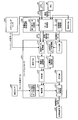
- FIG. 3 is a block diagram illustrating an example of the blade control device 200 according to the present embodiment.
- the blade control device 200 includes a lift cylinder 50, a sprocket 95, a proportional control valve 230, a hydraulic pump 240, a hydraulic motor 241, a hydraulic pump 245, and an input device 260.
- the blade control device 200 includes a hydraulic pressure sensor 250, a lift cylinder sensor 50S, a GPS receiver 80, and an IMU 90.
- the blade control device 200 includes a blade controller 210 and a target height generation device 220.
- the hydraulic pump 240 is a hydraulic pump (traveling hydraulic pump) for traveling the traveling device 20.
- the hydraulic pump 240 is connected to the engine.
- the hydraulic motor 241 is a hydraulic motor (traveling hydraulic motor) for causing the traveling device 20 to travel.
- the hydraulic motor 241 is connected to the sprocket 95.
- the transmission includes an HST (Hydraulic Static Transmission) having a hydraulic pump 240 connected to the engine and a hydraulic motor 241 connected to the sprocket 95. Hydraulic fluid is supplied from the hydraulic pump 240 to the hydraulic motor 241. As a result, the hydraulic motor 241 operates and the sprocket 95 is driven.
- the hydraulic oil is supplied to the hydraulic motor 241 by driving the hydraulic pump 240.
- the hydraulic motor 241 generates power by the supplied hydraulic oil.
- the power generated by the hydraulic motor 241 is transmitted to the sprocket 95 connected to the hydraulic motor 241. Thereby, the traveling device 20 travels.
- the hydraulic pump 245 is a hydraulic pump (working machine hydraulic pump) for moving the blade 40.
- the proportional control valve 230 is disposed between the lift cylinder 50 and the hydraulic pump 245.
- the hydraulic pump 245 supplies hydraulic oil to the lift cylinder 50 via the proportional control valve 230.
- the lift cylinder 50 is driven based on the hydraulic oil controlled by the proportional control valve 230.
- the input device 260 includes an operation lever and a decelerating pedal operated by an operator.
- the blade controller 210 includes a computer system having a processor such as a CPU.
- the target height generator 220 includes a computer system having a processor such as a CPU.
- the blade controller 210 outputs a drive command for driving the lift cylinder 50 that can move the blade 40 in the vertical direction.
- the blade controller 210 outputs a control signal based on the drive command to the proportional control valve 230 that controls the hydraulic oil supplied to the lift cylinder 50.
- the blade controller 210 turns the blade drive command and the left and right traveling devices 20 according to the operation of the operation lever of the input device 260, respectively. Further, the blade controller 210 adjusts the output of the transmission and changes the vehicle speed in accordance with the operation of the de- sedation pedal of the input device 260.
- the target height generator 220 calculates target height data indicating the target position of the cutting edge 40P.
- the hydraulic sensor 250 transmits pressure data (blade load data) to the blade controller 210.
- the lift cylinder sensor 50S transmits lift cylinder length data indicating the lift cylinder length L of the lift cylinder 50 to the blade controller 210.
- the GPS receiver 80 transmits GPS data to the target height generation device 220.
- the target height generation device 220 transmits GPS data to the blade controller 210.
- the GPS receiver 80 may transmit GPS data to the blade controller 210.
- the IMU 90 transmits vehicle body inclination angle data indicating the inclination angle of the pitch and roll in the absolute coordinate system of the bulldozer 100 to the target height generation device 220.
- the target height generation device 220 transmits vehicle body tilt angle data to the blade controller 210. Note that the IMU 90 may transmit the vehicle body tilt angle data to the blade controller 210.
- the blade controller 210 acquires blade load data (pressure data) from the hydraulic sensor 250.
- the blade controller 210 acquires lift cylinder length data from the lift cylinder sensor 50S.
- the blade controller 210 acquires GPS data from the GPS receiver 80.
- the blade controller 210 acquires vehicle body tilt angle data from the IMU 90.
- the blade controller 210 calculates the GPS position (absolute position) of the GPS receiver 80 in the global coordinate system based on the GPS data (absolute position data).
- the global coordinate system is a coordinate system based on the origin (absolute reference position) fixed on the earth.
- the blade controller 210 calculates the lift angle ⁇ (see FIG. 2) of the blade 40 based on the lift cylinder length data.
- the blade controller 210 converts the coordinate system from the global coordinate system to the local coordinate system based on the lift angle ⁇ and the vehicle body dimension data, and then the position of the cutting edge 40P of the blade 40 with respect to the GPS receiver 80 in the local coordinate system ( Relative position) is calculated.
- the local coordinate system is a coordinate system based on the origin (vehicle body reference position) fixed to the vehicle body 10 of the bulldozer 100.
- the local coordinate system may be referred to as a vehicle body coordinate system.
- the vehicle body dimension data is known data and is stored in advance in the blade controller 210.
- the blade controller 210 includes GPS data indicating the absolute position of the GPS receiver 80 in the global coordinate system, local position data indicating the relative position of the cutting edge 40P with respect to the GPS receiver 80 in the local coordinate system, and vehicle body inclination indicating the inclination angle of the vehicle body 10. Based on the corner data, the position (actual height) of the cutting edge 40P in the global coordinate system is calculated. That is, the blade controller 210 performs GPS data (absolute position data) indicating the GPS position (absolute position) of the vehicle body 10, vehicle body inclination angle data indicating the inclination angle of the vehicle body 10, and a lift indicating the stroke length of the lift cylinder 50. Based on the cylinder length data, the actual position (actual height) of the cutting edge 40P is calculated.
- the target height generation device 220 acquires GPS data from the GPS receiver 80.
- the target height generation device 220 acquires vehicle body tilt angle data from the IMU 90.
- the target height generation device 220 stores in advance design surface data indicating a design surface that is a three-dimensional design landform indicating a target shape to be excavated in the work area.
- the target height generation device 220 changes from the global coordinate system to the local coordinate system based on the vehicle body dimension data, the lift angle ⁇ obtained from the cylinder length data, the GPS data, the vehicle body inclination angle data, and the design surface data. Conversion is performed to calculate the target position (target height) of the cutting edge 40P in the local coordinate system.
- the target height generation device 220 transmits target height data indicating the calculated target height to the blade controller 210.
- the blade controller 210 acquires target height data.
- the blade controller 210 outputs a control signal based on the drive command to the proportional control valve 230 so that the deviation between the actual height and the target height is small.
- the control signal includes a current.
- the blade controller 210 outputs a current corresponding to the current value obtained based on the actual height and the target height to the proportional control valve 230 as a control signal.
- the blade controller 210 estimates the height (predicted height) of the future cutting edge 40P.
- the blade controller 210 outputs a control signal based on the drive command to the proportional control valve 230 so that the deviation between the predicted height and the target height is small.
- the control signal includes a current.
- the blade controller 210 outputs a current corresponding to the current value obtained based on the predicted height and the target height to the proportional control valve 230 as a control signal.
- the opening degree of the proportional control valve 230 is controlled by a current output from the blade controller 210 as a control signal.
- the current output as a control signal from the blade controller 210 can be adjusted by the input device 260.
- FIG. 4 is a functional block diagram illustrating an example of the blade controller 210 and the target height generation device 220 according to the present embodiment.
- the blade controller 210 includes a vehicle data acquisition unit 211, an actual height calculation unit 212, a determination unit 213, an estimation unit 214, a filter unit 215, and a target height data acquisition unit 216. , A target height correction unit 217, a blade load data acquisition unit 218, a blade control unit 219, and a storage unit 300.
- the target height generation device 220 includes a design surface data storage unit 221, a data acquisition unit 222, and a target height calculation unit 223.
- the vehicle data acquisition unit 211 acquires GPS data from the GPS receiver 80.
- the vehicle data acquisition unit 211 acquires vehicle body tilt angle data from the IMU 90.
- the vehicle data acquisition unit 211 acquires lift cylinder length data from the lift cylinder sensor 50S.
- the actual height calculation unit 212 calculates the actual height (actual height) of the cutting edge 40P based on the vehicle body dimension data, GPS data, vehicle body inclination angle data, and lift cylinder length data.
- the determination unit 213 performs a predetermined determination based on the deviation between the target height and the actual height of the cutting edge 40P.
- the estimation unit 214 estimates the predicted height of the future cutting edge 40P based on the drive command output in the past and the actual height of the current cutting edge 40P.
- the filter unit 215 filters target height data indicating the target height transmitted from the target height generation device 220.
- the filter unit 215 includes a Kalman filter.
- the target height data acquisition unit 216 acquires target height data indicating the target height calculated by the target height generation device 220. In the present embodiment, the target height data acquisition unit 216 acquires the target height data filtered by the filter unit 215.
- the target height correction unit 217 estimates the future target height based on the past target height and the current target height.
- the determination unit 213 determines a predetermined level to be described later. Make a decision.
- the blade load data acquisition unit 218 acquires blade load data indicating the load of the blade 40 from the hydraulic sensor 250.
- the blade control unit 219 performs proportional control so that the deviation between the predicted height and the target height is reduced based on the predicted height of the future cutting edge 40P estimated by the estimation unit 214 and the current target height of the cutting edge 40P.
- a control signal based on the drive command is output to the valve 230.
- the storage unit 300 stores various maps used for control of the blade controller 210.
- the storage unit 300 is a map showing the relationship between the current as a control signal output to the proportional control valve 230 and the cylinder speed of the lift cylinder 50 when the current is supplied to the proportional control valve 230.
- the design surface data storage unit 221 holds in advance design surface data indicating a design surface that is a three-dimensional design landform of a target shape to be excavated.
- the data acquisition unit 222 acquires GPS data from the GPS receiver 80.
- the data acquisition unit 222 acquires vehicle body tilt angle data from the IMU 90.
- the data acquisition unit 222 acquires design surface data from the design surface data storage unit 221.
- the target height calculation unit 223 includes GPS data indicating the absolute position of the vehicle body 10, vehicle body inclination angle data indicating the inclination angle of the vehicle body 10, and a design indicating a design surface that is a three-dimensional design landform of the target shape to be excavated. Based on the surface data, the target height of the cutting edge 40P is calculated. The target height calculation unit 223 transmits target height data indicating the calculated target height to the filter unit 215.
- target height data indicating the target height at the first time point (current time) calculated by the target height calculator 223 of the target height generator 220 is acquired by the target height data acquisition unit 216.
- the estimation unit 214 outputs the drive command output from the blade control unit 210 at the second time point (past time point) before the first time point and the actual height indicating the actual height of the cutting edge 40P at the first time point.
- the estimated height of the cutting edge 40P at the third time point (future time point) after the first time point is estimated based on the height data.
- the blade control unit 219 outputs a drive command based on the predicted height at the third time point and the target height at the first time point so that the deviation between the predicted height and the target height becomes small at the first time point.
- the target height calculator 223 calculates the target height at a predetermined cycle (for example, every 10 milliseconds).
- the actual height calculation unit 212 calculates the actual height at a predetermined cycle (for example, every 10 milliseconds).
- the second time point (past time point) is, for example, a time point (period 10 milliseconds before) one cycle before the first time point (current time).
- the third time point (future time point) is, for example, a time point after one cycle (time point after 10 milliseconds) from the first time point (current time point).
- the blade control unit 219 outputs a drive command based on the predicted height and the target height when the difference between the actual height and the target height has a predetermined relationship.
- the blade controller 219 outputs a drive command based on the actual height and the target height when the difference between the actual height and the target height is not a predetermined relationship.
- the determination unit 2113 determines that the first deviation between the target height at the first time point and the actual height at the first time point is greater than the second deviation between the target height at the second time point and the actual height at the second time point. Determine whether it is larger.
- the blade control unit 219 determines the predicted height and the target at the first time based on the predicted height at the third time and the target height at the first time. A drive command is output so that the deviation from the height is small.
- the blade controller 219 determines that the actual height and the target at the first time point are based on the actual height at the first time point and the target height at the first time point. A drive command is output so that the deviation from the height is small.
- the target height correction unit 217 is configured such that the target height data acquisition unit 216 acquires the target height from the target height generation device 220 at the first time point, and the target height data acquisition unit 216 acquires the target height generation device at the second time point. Based on the target height acquired from 220, the target height (corrected target height) at the third time point is estimated.
- the estimated target height (corrected target height) is used as the target height at the first time point.
- the determination unit 213 determines that the first deviation between the target height at the first time point (corrected target height) and the actual height at the first time point is the second deviation between the target height at the second time point and the actual height at the second time point. It is judged whether it is larger than.
- the blade control unit 219 determines whether the first height is based on the predicted height and the target height estimated by the target height correction unit 217. At the time, the drive command is output so that the deviation between the predicted height and the target height is small.
- the blade control unit 219 determines whether the first height is based on the actual height and the target height estimated by the target height correction unit 217. At the time, the drive command is output so that the deviation between the actual height and the target height is small.
- FIG. 5 is a flowchart illustrating an example of a blade control method according to the present embodiment.
- the vehicle data acquisition unit 211 acquires GPS data, vehicle body tilt angle data, and lift cylinder length data.
- the actual height calculation unit 212 calculates the actual height of the cutting edge 40P at the first time point based on the GPS data at the first time point, the vehicle body tilt angle data at the first time point, and the cylinder length data at the first time point. (Step SP1). As described above, in the present embodiment, the actual height calculation unit 212 calculates the actual height of the cutting edge 40P at a predetermined cycle (every 10 milliseconds).
- the data acquisition unit 222 acquires GPS data, vehicle body tilt angle data, and design surface data.
- the target height calculation unit 223 calculates the target height of the cutting edge 40P based on the GPS data, the vehicle body tilt angle data, and the cylinder length data. As described above, in the present embodiment, the target height calculator 223 calculates the target height of the cutting edge 40P at a predetermined cycle (every 10 milliseconds).
- the target height data indicating the target height calculated by the target height calculator 223 is transmitted to the blade controller 210 at a predetermined cycle (every 10 milliseconds).
- the target height data acquisition unit 216 acquires target height data indicating the target height at the first time point calculated by the target height generation device 220 via the filter unit 215 (step SP2).
- the blade controller 210 has acquired the actual height data at the first time point and the target height data at the first time point.
- the target height data acquired by the filter unit 215 is acquired by the target height data acquisition unit 216.
- the filter unit 215 preferably includes a filter with a small time delay, and includes, for example, a Kalman filter.
- the target height data calculated by the target height calculator 223 also changes every moment. Even if an attempt is made to control the blade 40 using a hydraulic system including the lift cylinder 50 and the proportional control valve 230 based on the target height data that changes every moment, the control cannot catch up and a control failure such as hunting may occur. There is sex. Therefore, in the present embodiment, the target height data is filtered, and the blade 40 is controlled using the filtered target height data. Thereby, generation
- FIG. 6 is a diagram for explaining the effect of the filter unit 215.
- a line LO indicates target height data output from the target height calculator 223.
- the target height data output from the target height calculation unit 223 also changes every moment as the inclination angle of the vehicle body 10 changes.
- the line LC indicates target height data after being filtered by the filter unit 215 including the Kalman filter. That is, the line LC indicates the target height data output from the filter unit 215 to the target height data acquisition unit 216. As indicated by the line LC, the target height data is converted into smooth data without causing a large delay by the filter unit 215 including the Kalman filter. By controlling the blade 40 using the filtered target height data, the occurrence of control failure is suppressed.
- the target height data acquired by the target height data acquisition unit 216 is transmitted to the target height correction unit 217.
- the target height correction unit 217 corrects the target height data supplied from the target height data acquisition unit 216 (step SP3).
- the target height data is calculated based on GPS data, vehicle body tilt angle data, and the like.
- the blade controller 210 deviates from the target height data based on the vehicle body tilt angle data in the past (10 milliseconds before) one cycle ago.
- the blade 40 is controlled so as to be small.
- the inclination angle of the vehicle body 10 changes every moment.
- the blade 40 may not be able to sufficiently follow the design surface. For example, there is a possibility that a vertical movement (swell) of the blade unintended by the operator may occur at a specific vehicle speed.
- the blade controller 210 corrects the target height data supplied from the target height generation device 220 in order to suppress control failure due to the delay of the target height generation device 220, and the target Height data (corrected target height data) is generated.
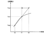
- FIG. 7 is a diagram for explaining an example of the correction target height.
- the target height data acquisition unit 216 acquires the target height data Tm1 from the target height generation device 220, and the second before the first time point t1. It is assumed that the target height data acquisition unit 216 acquires the target height data Tm2 from the target height generation device 220 at the time point (past time point) t2.
- the target height correction unit 217 estimates target height data Tm3 at a third time point (future time point) t3 after the first time point t1.
- the target height correction unit 217 performs the calculation of equation (1).
- Tm3 Tm1 + (Tm1-Tm2) ⁇ G (1)
- G is a gain.
- the blade controller 210 uses the target height data (corrected target height data) Tm3 to output a control signal based on a drive command for controlling the blade 40 at the first time point t1. That is, the blade controller 210 performs control by setting the target height at the first time point t1 to the target height data Tm3.
- the target height at the future time point (third time point) is set based on the target height data at the current time point (first time point) and the target height data at the past time point (second time point).
- a target height at a future time point may be set based on target height data at a certain past time point (for example, the second time point) and target height data at a time point before the past time point.
- the actual height data Tr1 at the first time point t1 calculated by the actual height calculation unit 212 and the target height data Tm3 at the first time point t1 corrected by the target height correction unit 217 are transmitted to the determination unit 213.
- the determination unit 213 determines the first deviation ⁇ 1 between the target height data Tm3 at the first time point t1 and the actual height data Tr1 at the first time point t1, the target height data Tm2 at the second time point t2, and the second time point t2.
- the second deviation ⁇ 2 is compared with the actual height data Tr2 (step SP4).
- the determination unit 213 determines that the first deviation ⁇ 1 between the target height data Tm3 at the first time point t1 and the actual height data Tr1 at the first time point t1 is the difference between the target height data Tm2 at the second time point t2 and the second time point t2. It is determined whether it is larger than the second deviation ⁇ 2 from the actual height data Tr2 (step SP5).
- the estimation unit 214 estimates the predicted height (step SP6).
- the estimation unit 214 does not estimate the predicted height, and the blade control unit 219 determines that the actual height data Tr1 at the first time point t1 and the first Based on the target height data Tm1 at the time point t1, a drive command is output so that the deviation between the actual height data Tr1 and the target height data Tm1 becomes small at the first time point t1 (step SP8).
- dead time due to the hydraulic system is generated. If there is a dead time of the hydraulic system with respect to the control signal, it may be difficult to make the cutting edge 40P of the blade 40 follow the design surface. If the gain is increased to improve the responsiveness, an overshoot occurs due to the dead time, and it may be difficult to make the cutting edge 40P of the blade 40 follow the design surface.
- the estimated height data Tr3 of the cutting edge 4P at the third time point t3 after the first time point t1 is estimated without using the actual height data Tr1 of the cutting edge 4P at the first time point t1.
- the drive command for controlling the blade 40 is output using the estimated predicted height data Tr3.
- the estimated height data Tr3 is estimated, and the estimated height data Tr3 is used to perform control at the first time point t1, so that the cutting edge 40P can be used even in a situation where dead time due to the hydraulic system occurs. Can approach the target height.
- actual height data Tr1 of the cutting edge 40P at the first time point t1 is calculated.
- the actual height data Tr2 of the cutting edge 40P at the second time point t2 before the first time point t1 is calculated.
- a drive command is output from the blade controller 219.
- the estimation unit 214 starts from the first time point t1 based on the drive command output from the blade control unit 219 at the second time point t2 and the actual height data Tr1 indicating the actual height of the cutting edge 40P at the first time point t1. Also, predicted height data Tr3 indicating the predicted height of the cutting edge 40P at the third time point t3 is estimated.
- the drive command includes a target cylinder speed command for the lift cylinder 50.
- the storage unit 300 stores a map indicating the relationship between the current as a control signal output to the proportional control valve 230 and the cylinder speed of the lift cylinder 50 when the current is supplied to the proportional control valve 230. Yes.
- the blade control unit 219 outputs a control signal (current) to the proportional control valve 230 so that the lift cylinder 50 operates at a cylinder speed according to the target value based on the map of the storage unit 300.
- the drive command at the second time point t2 includes the target cylinder speed command for the lift cylinder 50 at the second time point t2.
- the estimation unit 214 estimates the predicted height based on the actual height data Tr1 at the first time point t1, the target cylinder speed (command speed) Vr2 at the second time point t2, and the period ts (10 milliseconds in this example). Data Tr3 is estimated.
- the estimation unit 214 performs the calculation of equation (2).
- Tr3 Tr1 + Vr2 ⁇ ts ⁇ G (2)
- Vr2 is a target cylinder speed (command speed) at the second time point t2.
- ts is a period.
- G is a gain.
- the blade controller 210 outputs a control signal based on a drive command for controlling the blade 40 at the first time point t1 using the predicted height data Tr3.
- the equation (2) uses the command speed Vr2 at the second time point t2 one cycle before the first time point t1 (1 ⁇ 10 milliseconds). Not only the command speed Vr2 at the second time point t2 one cycle before the first time point t1, but also the command speed Vr22 at the time point t22 two cycles before (2 ⁇ 10 ms), three cycles before (3 ⁇ 10 ms) ) Command speed Vr23 at time t23,..., Command speed Vr2n at time t2n before n cycles (n ⁇ 10 milliseconds) may be used. That is, the estimation unit 214 may perform the calculation of equation (3).
- Tr3 Tr1 + (Vr2 + Vr22 +... + Vr2n) ⁇ ts ⁇ G (3)
- the predicted height data Tr3 is estimated, and a drive command is output at the first time point t1 based on the predicted height data Tr3, so that even if the gain G is high in order to increase responsiveness. The occurrence of overshoot is suppressed.
- the gain G can be arbitrarily determined.
- the gain G is adjusted based on blade load data.
- the blade controller 210 includes a blade load data acquisition unit 218 that acquires blade load data indicating a load applied to the blade 40.
- the estimation unit 214 may adjust the gain G for calculating the predicted height data Tr3 based on the blade load data. For example, when the blade load data is large, the estimation unit 214 decreases the gain G. When the blade load is high, the predicted height data Tr3 may greatly deviate from the true value (the height of the true cutting edge 40P at the first time point t1). When the blade load is large, by reducing the gain G, it is possible to suppress the predicted height data Tr3 from greatly deviating from the true value.
- the blade control unit 219 determines the predicted height data Tm3 and the target height data at the first time point t1 based on the predicted height data Tr3 and the target height data Tm3. A drive command is output so that the deviation from Tr3 is small (step SP7). Thereby, the fall of the followability of the blade 40 with respect to a design surface is suppressed.
- the blade control unit 219 outputs a drive command so that the deviation between the predicted height data Tm3 and the target height data Tr3 is reduced by the sliding mode control. Thereby, high responsiveness of the blade 40 is realized.
- the blade controller 219 may output a drive command so that the deviation between the predicted height data Tm3 and the target height data Tr3 is reduced by PID control.
- the predicted height at the future time point is estimated from the actual height data at the current time point (first time point) and the drive command at the past time point (second time point).
- a predicted height at a future time point may be estimated based on actual height data at a certain past time point (for example, the second time point) and a drive command at a time point before the past time point. That is, the drive command output from the blade control unit 219 at the second time point t2 before the first time point t1 and the time point before the first time point t1 or the first time point t1 (for example, time point t2, time point t22,... Based on the actual height data indicating the actual height of the cutting edge 40P at time t2n), the predicted height of the cutting edge 40P at the third time point t3 after the first time point t1 may be estimated.
- step SP5 when it is determined in step SP5 that the first deviation ⁇ 1 is larger than the second deviation ⁇ 2, or when it is determined that the first deviation ⁇ 1 and the second deviation ⁇ 2 are equal, or When it is determined that the first deviation ⁇ 1 is equal to or greater than a predetermined threshold (step SP5: Yes), the estimation unit 214 does not estimate the predicted height, and the blade control unit 219 causes the first time point t1. Driving based on the actual height data Tr1 and the target height data Tm1 at the first time point t1 so that the deviation between the actual height data Tr1 and the target height data Tm1 becomes small at the first time point t1. A command is output (step SP8).
- the drive command is output using the actual height data Tr1 at the first time point t1 without using the predicted height data Tr3.
- the predicted height data Tr3 may be replaced with the actual height data Tr1 by executing a process for setting the gain G to zero.
- the occurrence of overshoot is suppressed by using the predicted height data Tr3.
- the predicted height data Tr3 when used, the output of the drive command tends to be suppressed. If the actual height is moving gradually away from the target height, or if the difference between the actual height and the target height is greater than a predetermined threshold, the actual height will quickly reach the target height. It may be difficult to get close.
- the blade controller 219 is based on the actual height data Tr1 at the first time point t1 and the target height data Tm1 at the first time point t1.
- the drive command is output so that the deviation between the actual height data Tr1 and the target height data Tm1 becomes small. As a result, the actual height can quickly approach the target height.
- FIG. 9 is a diagram illustrating an effect when the target height is corrected by the target height correction unit 217.
- the target height after correction can be closer to the ideal target height than the target height before correction.
- the ideal target height is a target height that is derived according to the actual behavior of the vehicle body 10 by detecting the actual behavior of the vehicle body 10.
- a behavior close to the ideal target height can be acquired from the target height before correction.
- the delay time from the blade drive command to the actual driving of the blade is reduced.
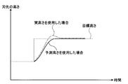
- FIG. 10 shows an example of the height of the cutting edge 40P when the blade 40 is controlled using the actual height without using the predicted height, and the cutting edge when the blade 40 is controlled using the predicted height.
- An example of a height of 40P is shown.
- FIG. 10 shows that when the bulldozer 100 is leveling using the blade 40, in other words, when the traveling device 20 of the bulldozer 100 is traveling with a predetermined load applied to the blade 40, the target height fluctuates stepwise.
- the height of the cutting edge 40P when the blade 40 is controlled using the actual height and the height of the cutting edge 40P when the blade 40 is controlled using the predicted height are shown.
- the target height calculated by the target height generating device 220 varies stepwise as shown in FIG.
- the overshoot of the blade 40 is suppressed as shown in FIG.
- the blade 40 can converge to the target height without causing overshoot.
- the bulldozer 100 can level the ground to a desired shape.
- the drive command output from the blade control unit 219 at the second time point t2 before the first time point t1 and the actual height of the cutting edge 40P at the first time point t1.
- estimated height data Tr3 indicating the predicted height of the cutting edge 40P at the third time point t3 after the first time point t1 is estimated, and the predicted height data Tr3 and the target height are estimated. Since the drive command is output based on the data Tm1, even if there is a dead time of the hydraulic system, the gain is increased and the response of the blade 40 is improved, and the occurrence of overshoot is suppressed. be able to.
- the bulldozer 100 can level the ground to a desired shape.
- the blade control unit 219 controls the blade 40 by sliding mode control, which is a modern control theory.
- the sliding mode control has a high possibility of obtaining high responsiveness compared to the PID control. Due to the dead time of the hydraulic system, in a control system that adopts sliding mode control and has improved responsiveness, overshoot may occur depending on the load and running conditions. According to the present embodiment, by controlling the blade 40 using the predicted height data Tr3, overshoot and the like can be suppressed and controllability can be improved.
- the target height calculation unit 223 calculates the target height and the actual height calculation unit 212 calculates the actual height at a predetermined cycle ts.
- the first time point t1, the second time point t2, and the third time point t3 are determined based on the period ts. Thereby, the ground can be leveled to a desired shape using the blade 40.
- the gain G for calculating the predicted height data Tr3 is adjusted based on the blade load data. As a result, the predicted height data Tr3 caused by a change in blade load is prevented from greatly deviating from the true value, and a decrease in accuracy of the predicted height data Tr3 is suppressed.
- the drive command is output using the actual height data Tr1 at the first time point t1 without using the predicted height data Tr3. Thereby, when the actual height is away from the target height, the actual height can be quickly approached to the target height.
- the target height data Tm3 at the third time point t3 is estimated based on the target height data Tm1 at the first time point t1 and the target height data Tm2 at the second time point t2,
- the blade 40 is controlled so that the target height data Tm3 and the predicted height data Tr3 approach each other. Therefore, even when processing (including calculation and output) of the target height generation device 220 is delayed, the blade 40 is controlled so that the delay is offset. Accordingly, the present invention can be applied to a case where blade control based on the actual height prediction is performed, and the bulldozer 100 can level the ground into a desired shape.
- Work vehicle 100 may be a motor grader having a blade mechanism.
Landscapes
- Engineering & Computer Science (AREA)
- Mining & Mineral Resources (AREA)
- Civil Engineering (AREA)
- General Engineering & Computer Science (AREA)
- Structural Engineering (AREA)
- Mechanical Engineering (AREA)
- Physics & Mathematics (AREA)
- Acoustics & Sound (AREA)
- Electromagnetism (AREA)
- Optics & Photonics (AREA)
- Operation Control Of Excavators (AREA)
- Remote Sensing (AREA)
- Radar, Positioning & Navigation (AREA)
- Computer Networks & Wireless Communication (AREA)
- General Physics & Mathematics (AREA)
Abstract
Description
本実施形態に係るブルドーザ100の全体構成について説明する。図1に示すように、ブルドーザ100は、車体10と、走行装置20と、リフトフレーム30と、ブレード40と、リフトシリンダ50と、アングルシリンダ60と、チルトシリンダ70と、GPSレシーバ80と、IMU(Inertial Measurement Unit)90と、スプロケット95と、油圧ポンプ240と、油圧モータ241と、油圧ポンプ245と、油圧センサ250と、を備える。
次に、本実施形態に係るブレード制御装置200の一例について説明する。図3は、本実施形態に係るブレード制御装置200の一例を示すブロック図である。
図4に示すように、ブレードコントローラ210は、車両データ取得部211と、実高さ演算部212と、判定部213と、推定部214と、フィルタ部215と、目標高さデータ取得部216と、目標高さ補正部217と、ブレード負荷データ取得部218と、ブレード制御部219と、記憶部300と、を含む。
設計面データ格納部221は、掘削対象の目標形状の3次元の設計地形である設計面を示す設計面データを予め保持する。
次に、本実施形態に係るブレード制御方法について説明する。図5は、本実施形態に係るブレード制御方法の一例を示すフローチャートである。
以上説明したように、本実施形態によれば、第1時点t1よりも前の第2時点t2でブレード制御部219から出力された駆動指令と、第1時点t1の刃先40Pの実高さを示す実高さデータTr1とに基づいて、第1時点t1よりも後の第3時点t3の刃先40Pの予測高さを示す予測高さデータTr3を推定し、予測高さデータTr3と目標高さデータTm1とに基づいて、駆動指令を出力するようにしたので、油圧システムのむだ時間が存在しても、ゲインを大きくしてブレード40の応答性を向上しつつ、オーバーシュートの発生を抑制することができる。
11 運転室
12 エンジン室
20 走行装置
21 クローラ
30 リフトフレーム
31 球関節部
32 ピッチ支持リンク
33 支柱部
40 ブレード
40P 刃先
41 自在継手
42 ピッチング継手
50 リフトシリンダ
50S リフトシリンダセンサ
60 アングルシリンダ
70 チルトシリンダ
80 GPSレシーバ
90 IMU
95 スプロケット
100 ブルドーザ(作業車両)
200 ブレード制御装置
210 ブレードコントローラ
211 車両データ取得部
212 実高さ演算部
213 判定部
214 推定部
215 フィルタ部
216 目標高さデータ取得部
217 目標高さ補正部
218 ブレード負荷データ取得部
219 ブレード制御部
220 目標高さ生成装置
221 設計面データ格納部
222 データ取得部
223 目標高さ演算部
230 比例制御弁
240 油圧ポンプ
241 油圧モータ
245 油圧ポンプ
250 油圧センサ
260 インプット装置
300 記憶部
L リフトシリンダ長(リフトシリンダのストローク長さ)
θ リフト角
Claims (8)
- 作業車両の車体に上下方向に移動可能に支持されるブレードの刃先の高さを制御するブレード制御装置であって、
前記ブレードを上下方向に移動可能な油圧シリンダを駆動する駆動指令を出力するブレード制御部と、
前記車体の絶対位置を示す絶対位置データと、前記車体の傾斜角を示す車体傾斜角データと、掘削対象の目標形状の3次元の設計地形である設計面を示す設計面データとに基づいて、前記刃先の目標高さを算出する目標高さ生成装置と、
前記目標高さ生成装置で算出された第1時点の目標高さを示す目標高さデータを取得する目標高さデータ取得部と、
前記第1時点の前記絶対位置データと、前記車体傾斜角データと、前記油圧シリンダのストローク長さを示すシリンダ長データとに基づいて、前記第1時点の前記刃先の実高さを算出する実高さ演算部と、
前記第1時点よりも前の第2時点で前記ブレード制御部から出力された前記駆動指令と、前記第1時点又は前記第1時点よりも前の時点の前記刃先の実高さを示す実高さデータとに基づいて、前記第1時点よりも後の第3時点の前記刃先の予測高さを推定する推定部と、
を備え、
前記ブレード制御部は、前記第3時点の前記予測高さと、前記第1時点の前記目標高さとに基づいて、前記第1時点において、前記予測高さと前記目標高さとの偏差が小さくなるように、第1駆動指令を出力する、
ブレード制御装置。 - 前記実高さ演算部は、所定の周期で前記実高さを算出し、
前記第2時点は、前記第1時点よりも1周期前の時点を含み、
前記第3時点は、前記第1時点よりも1周期後の時点を含む、
請求項1に記載のブレード制御装置。 - 前記第2時点の前記駆動指令は、前記油圧シリンダの目標シリンダ速度指令を含み、
前記推定部は、前記第1時点又は前記第1時点よりも前の時点の実高さと、前記第2時点の駆動指令と、前記周期とに基づいて、前記予測高さを推定する、
請求項2に記載のブレード制御装置。 - 前記ブレードにかかる負荷を示すブレード負荷データを取得するブレード負荷データ取得部を備え、
前記推定部は、前記ブレード負荷データに基づいて、前記予測高さを算出するためのゲインを調整する、
請求項3に記載のブレード制御装置。 - 前記第1時点の前記目標高さと前記実高さとの第1偏差が、前記第2時点の前記目標高さと前記実高さとの第2偏差よりも大きいか否かを判定する判定部を備え、
前記ブレード制御部は、
前記第1偏差が前記第2偏差よりも小さいと判定されたとき、前記第1駆動指令を出力し、
前記第1偏差が前記第2偏差よりも大きいと判定されたとき、前記第1時点の実高さと、前記第1時点の目標高さとに基づいて、前記第1時点において、前記実高さと前記目標高さとの偏差が小さくなるように、第2駆動指令を出力する、
請求項1から請求項4のいずれか一項に記載のブレード制御装置。 - 前記第1時点で前記目標高さデータ取得部が前記目標高さ生成装置から取得した前記目標高さと、前記第2時点で前記目標高さデータ取得部が前記目標高さ生成装置から取得した前記目標高さとに基づいて、前記第3時点の前記目標高さを推定する目標高さ補正部を備え、
前記ブレード制御部は、前記第3時点の前記予測高さと、前記目標高さ補正部で推定された前記第3時点の前記目標高さとに基づいて、前記第1時点において、前記予測高さと前記目標高さとの偏差が小さくなるように、第1駆動指令を出力する、
請求項1から請求項5のいずれか一項に記載のブレード制御装置。 - 車体と、
前記車体に上下方向に移動可能に支持される刃先を有するブレードと、
請求項1から請求項6のいずれか一項に記載のブレード制御装置と、
を備える作業車両。 - 作業車両の車体に上下方向に移動可能に支持されるブレードの刃先の高さを制御するブレード制御方法であって、
前記ブレードを上下方向に移動可能な油圧シリンダを駆動する駆動指令を出力することと、
前記車体の絶対位置を示す絶対位置データと、前記車体の傾斜角を示す車体傾斜角データと、掘削対象の目標形状の3次元の設計地形である設計面を示す設計面データとに基づいて、前記刃先の目標高さを算出することと、
第1時点の前記目標高さを示す目標高さデータを取得することと、
前記第1時点の前記絶対位置データと、前記車体傾斜角データと、前記油圧シリンダのストローク長さを示すシリンダ長データとに基づいて、前記第1時点の前記刃先の実高さを算出することと、
前記第1時点よりも前の第2時点で出力された前記駆動指令と、前記第1時点又は前記第1時点よりも前の時点の前記刃先の実高さを示す実高さデータとに基づいて、前記第1時点よりも後の第3時点の前記刃先の予測高さを推定することと、
を含み、
前記第1時点において、前記第3時点の前記予測高さと、前記第1時点の前記目標高さとに基づいて、前記予測高さと前記目標高さとの偏差が小さくなるように、第1駆動指令が出力される、
ブレード制御方法。
Priority Applications (4)
| Application Number | Priority Date | Filing Date | Title |
|---|---|---|---|
| US14/428,470 US9903096B2 (en) | 2014-10-30 | 2014-10-30 | Blade control apparatus, work vehicle, and method of controlling a blade |
| CN201480002731.8A CN105745379B (zh) | 2014-10-30 | 2014-10-30 | 推土铲控制装置、作业车辆和推土铲控制方法 |
| JP2014554110A JP5807128B1 (ja) | 2014-10-30 | 2014-10-30 | ブレード制御装置、作業車両、及びブレード制御方法 |
| PCT/JP2014/078977 WO2015083469A1 (ja) | 2014-10-30 | 2014-10-30 | ブレード制御装置、作業車両、及びブレード制御方法 |
Applications Claiming Priority (1)
| Application Number | Priority Date | Filing Date | Title |
|---|---|---|---|
| PCT/JP2014/078977 WO2015083469A1 (ja) | 2014-10-30 | 2014-10-30 | ブレード制御装置、作業車両、及びブレード制御方法 |
Publications (1)
| Publication Number | Publication Date |
|---|---|
| WO2015083469A1 true WO2015083469A1 (ja) | 2015-06-11 |
Family
ID=53273242
Family Applications (1)
| Application Number | Title | Priority Date | Filing Date |
|---|---|---|---|
| PCT/JP2014/078977 Ceased WO2015083469A1 (ja) | 2014-10-30 | 2014-10-30 | ブレード制御装置、作業車両、及びブレード制御方法 |
Country Status (4)
| Country | Link |
|---|---|
| US (1) | US9903096B2 (ja) |
| JP (1) | JP5807128B1 (ja) |
| CN (1) | CN105745379B (ja) |
| WO (1) | WO2015083469A1 (ja) |
Cited By (10)
| Publication number | Priority date | Publication date | Assignee | Title |
|---|---|---|---|---|
| WO2018179962A1 (ja) * | 2017-03-30 | 2018-10-04 | 株式会社小松製作所 | 作業車両の制御システム、作業機の軌跡設定方法、及び作業車両 |
| WO2018179963A1 (ja) * | 2017-03-30 | 2018-10-04 | 株式会社小松製作所 | 作業車両の制御システム、作業機の軌跡設定方法、及び作業車両 |
| JP2019501317A (ja) * | 2015-12-22 | 2019-01-17 | キャタピラー トリンブル コントロール テクノロジーズ、 エルエルシー | 表面に基づくコスト関数およびノイズ値に基づく器具制御 |
| WO2020189048A1 (ja) * | 2019-03-20 | 2020-09-24 | ヤンマー株式会社 | 作業車両のブレード制御システム |
| JPWO2020203804A1 (ja) * | 2019-03-29 | 2020-10-08 | ||
| AU2019246074B2 (en) * | 2018-03-28 | 2022-03-10 | Komatsu Ltd. | Control system for work vehicle, method, and work vehicle |
| CN115210667A (zh) * | 2020-03-09 | 2022-10-18 | 丹佛斯公司 | 用于控制重型机械的系统和方法 |
| US11933018B2 (en) | 2018-05-29 | 2024-03-19 | Komatsu Ltd. | Blade control device and blade control method |
| US12031291B2 (en) | 2018-05-31 | 2024-07-09 | Komatsu Ltd. | Blade control device and blade control method |
| US12060694B2 (en) | 2018-05-31 | 2024-08-13 | Komatsu Ltd. | Blade control device and blade control method |
Families Citing this family (18)
| Publication number | Priority date | Publication date | Assignee | Title |
|---|---|---|---|---|
| US20170096794A1 (en) * | 2015-10-02 | 2017-04-06 | Caterpillar Inc. | Blade assembly having socket support plate |
| US10066370B2 (en) * | 2015-10-19 | 2018-09-04 | Caterpillar Inc. | Sensor fusion for implement position estimation and control |
| JP6861485B2 (ja) * | 2016-07-26 | 2021-04-21 | 株式会社小松製作所 | 作業車両の制御システム、制御方法、及び作業車両 |
| JPWO2017119517A1 (ja) * | 2017-01-13 | 2018-01-11 | 株式会社小松製作所 | 作業機械の制御システム、作業機械、作業機械の制御方法、及びナビゲーションコントローラ |
| CN106888588A (zh) * | 2017-03-08 | 2017-06-27 | 徐州迪惠尔工程机械有限公司 | 一种高效可调节的平地机 |
| CA3063687A1 (en) * | 2017-08-29 | 2019-12-06 | Komatsu Ltd. | Control system for work vehicle, method, and work vehicle |
| CN110945189A (zh) * | 2017-09-07 | 2020-03-31 | 住友建机株式会社 | 挖土机 |
| US10392774B2 (en) * | 2017-10-30 | 2019-08-27 | Deere & Company | Position control system and method for an implement of a work vehicle |
| KR102259549B1 (ko) * | 2018-03-12 | 2021-06-03 | 히다찌 겐끼 가부시키가이샤 | 작업 기계 |
| US10533301B1 (en) * | 2018-12-20 | 2020-01-14 | David Armas | GPS and laser grading control |
| JP2020033789A (ja) * | 2018-08-31 | 2020-03-05 | 株式会社神戸製鋼所 | 作業機械のブレード制御装置 |
| US10883248B2 (en) | 2018-10-22 | 2021-01-05 | Deere & Company | Road maintenance using stored maintenance passes |
| BE1028074B1 (nl) * | 2020-02-20 | 2021-09-20 | Deeptech Nv | Diepzeemijnbouwvoertuig |
| CN111576514B (zh) * | 2020-05-28 | 2022-03-15 | 江苏徐工工程机械研究院有限公司 | 找平控制方法及系统、控制器、平地机 |
| JP2022170460A (ja) * | 2021-04-28 | 2022-11-10 | 株式会社小松製作所 | 作業機械、及び作業機械を制御するための方法 |
| US12546088B2 (en) * | 2021-12-29 | 2026-02-10 | Trimble Inc. | Optimizing blade engagement depth using engine load data |
| US12523004B2 (en) * | 2022-05-27 | 2026-01-13 | Caterpillar Inc. | Systems and methods for determining poor implement penetration |
| CN120215254B (zh) * | 2025-05-27 | 2025-09-12 | 吉林农业大学 | 基于耕深预测结果的液压耕深调控方法、装置及系统 |
Citations (3)
| Publication number | Priority date | Publication date | Assignee | Title |
|---|---|---|---|---|
| JP2010539478A (ja) * | 2007-09-12 | 2010-12-16 | トプコン ポジショニング システムズ, インク. | 統合された全地球的航法衛星システム・センサおよび慣性センサを有する自動ブレード制御システム |
| JP2014084683A (ja) * | 2012-10-26 | 2014-05-12 | Komatsu Ltd | ブレード制御装置、作業機械及びブレード制御方法 |
| JP2014173321A (ja) * | 2013-03-08 | 2014-09-22 | Komatsu Ltd | ブルドーザ及びブレード制御方法 |
Family Cites Families (4)
| Publication number | Priority date | Publication date | Assignee | Title |
|---|---|---|---|---|
| US8655556B2 (en) | 2011-09-30 | 2014-02-18 | Komatsu Ltd. | Blade control system and construction machine |
| JP5442815B2 (ja) * | 2012-08-06 | 2014-03-12 | 株式会社小松製作所 | 作業機械及び作業機械のブレードの自動制御方法 |
| CN103874804B (zh) * | 2013-03-08 | 2015-11-25 | 株式会社小松制作所 | 推土机及推土铲控制方法 |
| US8972119B2 (en) * | 2013-03-15 | 2015-03-03 | Novatel Inc. | System and method for heavy equipment navigation and working edge positioning |
-
2014
- 2014-10-30 CN CN201480002731.8A patent/CN105745379B/zh not_active Expired - Fee Related
- 2014-10-30 JP JP2014554110A patent/JP5807128B1/ja active Active
- 2014-10-30 US US14/428,470 patent/US9903096B2/en active Active
- 2014-10-30 WO PCT/JP2014/078977 patent/WO2015083469A1/ja not_active Ceased
Patent Citations (3)
| Publication number | Priority date | Publication date | Assignee | Title |
|---|---|---|---|---|
| JP2010539478A (ja) * | 2007-09-12 | 2010-12-16 | トプコン ポジショニング システムズ, インク. | 統合された全地球的航法衛星システム・センサおよび慣性センサを有する自動ブレード制御システム |
| JP2014084683A (ja) * | 2012-10-26 | 2014-05-12 | Komatsu Ltd | ブレード制御装置、作業機械及びブレード制御方法 |
| JP2014173321A (ja) * | 2013-03-08 | 2014-09-22 | Komatsu Ltd | ブルドーザ及びブレード制御方法 |
Cited By (22)
| Publication number | Priority date | Publication date | Assignee | Title |
|---|---|---|---|---|
| JP2019501317A (ja) * | 2015-12-22 | 2019-01-17 | キャタピラー トリンブル コントロール テクノロジーズ、 エルエルシー | 表面に基づくコスト関数およびノイズ値に基づく器具制御 |
| US11268259B2 (en) | 2017-03-30 | 2022-03-08 | Komatsu Ltd. | Control system for work vehicle, method for setting trajectory of work implement, and work vehicle |
| US11578470B2 (en) | 2017-03-30 | 2023-02-14 | Komatsu Ltd. | Control system for work vehicle, method for setting trajectory of work implement, and work vehicle |
| JPWO2018179963A1 (ja) * | 2017-03-30 | 2020-02-06 | 株式会社小松製作所 | 作業車両の制御システム、作業機の軌跡設定方法、及び作業車両 |
| JPWO2018179962A1 (ja) * | 2017-03-30 | 2020-02-06 | 株式会社小松製作所 | 作業車両の制御システム、作業機の軌跡設定方法、及び作業車両 |
| AU2018245331B2 (en) * | 2017-03-30 | 2020-07-23 | Komatsu Ltd. | Control system for a work vehicle, method for setting trajectory of work implement, and work vehicle |
| WO2018179963A1 (ja) * | 2017-03-30 | 2018-10-04 | 株式会社小松製作所 | 作業車両の制御システム、作業機の軌跡設定方法、及び作業車両 |
| JP7050051B2 (ja) | 2017-03-30 | 2022-04-07 | 株式会社小松製作所 | 作業車両の制御システム、作業機の軌跡設定方法、及び作業車両 |
| WO2018179962A1 (ja) * | 2017-03-30 | 2018-10-04 | 株式会社小松製作所 | 作業車両の制御システム、作業機の軌跡設定方法、及び作業車両 |
| AU2019246074B2 (en) * | 2018-03-28 | 2022-03-10 | Komatsu Ltd. | Control system for work vehicle, method, and work vehicle |
| US11933018B2 (en) | 2018-05-29 | 2024-03-19 | Komatsu Ltd. | Blade control device and blade control method |
| US12060694B2 (en) | 2018-05-31 | 2024-08-13 | Komatsu Ltd. | Blade control device and blade control method |
| US12031291B2 (en) | 2018-05-31 | 2024-07-09 | Komatsu Ltd. | Blade control device and blade control method |
| JP2020153156A (ja) * | 2019-03-20 | 2020-09-24 | ヤンマーパワーテクノロジー株式会社 | 作業車両のブレード制御システム |
| JP7025364B2 (ja) | 2019-03-20 | 2022-02-24 | ヤンマーパワーテクノロジー株式会社 | 作業車両のブレード制御システム |
| WO2020189048A1 (ja) * | 2019-03-20 | 2020-09-24 | ヤンマー株式会社 | 作業車両のブレード制御システム |
| CN113366171A (zh) * | 2019-03-29 | 2021-09-07 | 株式会社小松制作所 | 作业车辆、作业车辆的控制装置以及作业车辆的方向确定方法 |
| JP7416769B2 (ja) | 2019-03-29 | 2024-01-17 | 株式会社小松製作所 | 作業車両、作業車両の制御装置、および作業車両の方向特定方法 |
| US12006656B2 (en) | 2019-03-29 | 2024-06-11 | Komatsu Ltd. | Work vehicle, control device for work vehicle, and method for specifying direction of work vehicle |
| WO2020203804A1 (ja) * | 2019-03-29 | 2020-10-08 | 株式会社小松製作所 | 作業車両、作業車両の制御装置、および作業車両の方向特定方法 |
| JPWO2020203804A1 (ja) * | 2019-03-29 | 2020-10-08 | ||
| CN115210667A (zh) * | 2020-03-09 | 2022-10-18 | 丹佛斯公司 | 用于控制重型机械的系统和方法 |
Also Published As
| Publication number | Publication date |
|---|---|
| JP5807128B1 (ja) | 2015-11-10 |
| US9903096B2 (en) | 2018-02-27 |
| CN105745379B (zh) | 2018-02-27 |
| JPWO2015083469A1 (ja) | 2017-03-16 |
| CN105745379A (zh) | 2016-07-06 |
| US20160122969A1 (en) | 2016-05-05 |
Similar Documents
| Publication | Publication Date | Title |
|---|---|---|
| JP5807128B1 (ja) | ブレード制御装置、作業車両、及びブレード制御方法 | |
| CN109099033B (zh) | 利用传感器融合反馈在机器中控制流体压力的方法和系统 | |
| JP5285805B1 (ja) | ブレード制御装置、作業機械及びブレード制御方法 | |
| JP7680473B2 (ja) | 静水圧旋回動作作動、監視、および制御システム | |
| US8770307B2 (en) | Blade control system, construction machine and blade control method | |
| JP7092560B2 (ja) | ブレード制御装置及びブレード制御方法 | |
| US10671074B2 (en) | Control system for work vehicle, method, and work vehicle | |
| WO2013047179A1 (ja) | ブレード制御システムおよび建設機械 | |
| JP6843039B2 (ja) | 作業機械 | |
| CN111971437B (zh) | 推土铲控制装置及推土铲控制方法 | |
| WO2023053700A1 (ja) | 作業機械を制御するためのシステムおよび方法 | |
| JP7092557B2 (ja) | ブレード制御装置及びブレード制御方法 | |
| WO2026094648A1 (ja) | 作業機械を制御するためのシステム及び方法 | |
| JP2023006408A (ja) | 作業機械、及び、作業機械を制御するための方法。 |
Legal Events
| Date | Code | Title | Description |
|---|---|---|---|
| ENP | Entry into the national phase |
Ref document number: 2014554110 Country of ref document: JP Kind code of ref document: A |
|
| WWE | Wipo information: entry into national phase |
Ref document number: 14428470 Country of ref document: US |
|
| 121 | Ep: the epo has been informed by wipo that ep was designated in this application |
Ref document number: 14868518 Country of ref document: EP Kind code of ref document: A1 |
|
| NENP | Non-entry into the national phase |
Ref country code: DE |
|
| 122 | Ep: pct application non-entry in european phase |
Ref document number: 14868518 Country of ref document: EP Kind code of ref document: A1 |