WO2015083195A1 - スクリュー真空ポンプ - Google Patents
スクリュー真空ポンプ Download PDFInfo
- Publication number
- WO2015083195A1 WO2015083195A1 PCT/JP2013/007063 JP2013007063W WO2015083195A1 WO 2015083195 A1 WO2015083195 A1 WO 2015083195A1 JP 2013007063 W JP2013007063 W JP 2013007063W WO 2015083195 A1 WO2015083195 A1 WO 2015083195A1
- Authority
- WO
- WIPO (PCT)
- Prior art keywords
- rotor
- oil
- screw
- hollow portion
- male
- Prior art date
- Legal status (The legal status is an assumption and is not a legal conclusion. Google has not performed a legal analysis and makes no representation as to the accuracy of the status listed.)
- Ceased
Links
Images





Classifications
-
- F—MECHANICAL ENGINEERING; LIGHTING; HEATING; WEAPONS; BLASTING
- F04—POSITIVE - DISPLACEMENT MACHINES FOR LIQUIDS; PUMPS FOR LIQUIDS OR ELASTIC FLUIDS
- F04C—ROTARY-PISTON, OR OSCILLATING-PISTON, POSITIVE-DISPLACEMENT MACHINES FOR LIQUIDS; ROTARY-PISTON, OR OSCILLATING-PISTON, POSITIVE-DISPLACEMENT PUMPS
- F04C18/00—Rotary-piston pumps specially adapted for elastic fluids
- F04C18/08—Rotary-piston pumps specially adapted for elastic fluids of intermeshing-engagement type, i.e. with engagement of co-operating members similar to that of toothed gearing
- F04C18/12—Rotary-piston pumps specially adapted for elastic fluids of intermeshing-engagement type, i.e. with engagement of co-operating members similar to that of toothed gearing of other than internal-axis type
- F04C18/14—Rotary-piston pumps specially adapted for elastic fluids of intermeshing-engagement type, i.e. with engagement of co-operating members similar to that of toothed gearing of other than internal-axis type with toothed rotary pistons
- F04C18/16—Rotary-piston pumps specially adapted for elastic fluids of intermeshing-engagement type, i.e. with engagement of co-operating members similar to that of toothed gearing of other than internal-axis type with toothed rotary pistons with helical teeth, e.g. chevron-shaped, screw type
-
- F—MECHANICAL ENGINEERING; LIGHTING; HEATING; WEAPONS; BLASTING
- F04—POSITIVE - DISPLACEMENT MACHINES FOR LIQUIDS; PUMPS FOR LIQUIDS OR ELASTIC FLUIDS
- F04C—ROTARY-PISTON, OR OSCILLATING-PISTON, POSITIVE-DISPLACEMENT MACHINES FOR LIQUIDS; ROTARY-PISTON, OR OSCILLATING-PISTON, POSITIVE-DISPLACEMENT PUMPS
- F04C25/00—Adaptations of pumps for special use of pumps for elastic fluids
- F04C25/02—Adaptations of pumps for special use of pumps for elastic fluids for producing high vacuum
-
- F—MECHANICAL ENGINEERING; LIGHTING; HEATING; WEAPONS; BLASTING
- F04—POSITIVE - DISPLACEMENT MACHINES FOR LIQUIDS; PUMPS FOR LIQUIDS OR ELASTIC FLUIDS
- F04C—ROTARY-PISTON, OR OSCILLATING-PISTON, POSITIVE-DISPLACEMENT MACHINES FOR LIQUIDS; ROTARY-PISTON, OR OSCILLATING-PISTON, POSITIVE-DISPLACEMENT PUMPS
- F04C29/00—Component parts, details or accessories of pumps or pumping installations, not provided for in groups F04C18/00 - F04C28/00
- F04C29/02—Lubrication; Lubricant separation
- F04C29/023—Lubricant distribution through a hollow driving shaft
-
- F—MECHANICAL ENGINEERING; LIGHTING; HEATING; WEAPONS; BLASTING
- F04—POSITIVE - DISPLACEMENT MACHINES FOR LIQUIDS; PUMPS FOR LIQUIDS OR ELASTIC FLUIDS
- F04C—ROTARY-PISTON, OR OSCILLATING-PISTON, POSITIVE-DISPLACEMENT MACHINES FOR LIQUIDS; ROTARY-PISTON, OR OSCILLATING-PISTON, POSITIVE-DISPLACEMENT PUMPS
- F04C2240/00—Components
- F04C2240/80—Other components
- F04C2240/807—Balance weight, counterweight
-
- F—MECHANICAL ENGINEERING; LIGHTING; HEATING; WEAPONS; BLASTING
- F04—POSITIVE - DISPLACEMENT MACHINES FOR LIQUIDS; PUMPS FOR LIQUIDS OR ELASTIC FLUIDS
- F04C—ROTARY-PISTON, OR OSCILLATING-PISTON, POSITIVE-DISPLACEMENT MACHINES FOR LIQUIDS; ROTARY-PISTON, OR OSCILLATING-PISTON, POSITIVE-DISPLACEMENT PUMPS
- F04C29/00—Component parts, details or accessories of pumps or pumping installations, not provided for in groups F04C18/00 - F04C28/00
- F04C29/0021—Systems for the equilibration of forces acting on the pump
-
- F—MECHANICAL ENGINEERING; LIGHTING; HEATING; WEAPONS; BLASTING
- F04—POSITIVE - DISPLACEMENT MACHINES FOR LIQUIDS; PUMPS FOR LIQUIDS OR ELASTIC FLUIDS
- F04C—ROTARY-PISTON, OR OSCILLATING-PISTON, POSITIVE-DISPLACEMENT MACHINES FOR LIQUIDS; ROTARY-PISTON, OR OSCILLATING-PISTON, POSITIVE-DISPLACEMENT PUMPS
- F04C29/00—Component parts, details or accessories of pumps or pumping installations, not provided for in groups F04C18/00 - F04C28/00
- F04C29/04—Heating; Cooling; Heat insulation
Definitions
- the present invention relates to a screw vacuum pump.
- the same type of pump may be used as long as it does not depend on the exhaust speed, and the trouble of selecting a pump for each exhaust location does not occur. If the pumps of the above type are realized at low cost and commercialized, the degree of spread will be significant, and it is easily expected to greatly contribute to the development of the industry.
- the screw vacuum pump of the first aspect of the present invention has a male rotor and a female rotor having screw teeth that mesh with each other,
- the screw teeth of the male and female rotors are an unequal lead unequal inclination angle screw part formed on the upper end side in the rotation axis direction and the unequal lead unequal inclination formed on the lower end side in the rotation axis direction.
- At least one of the male rotor and the female rotor has a hollow portion that opens at an upper end surface and a lower end surface in the rotation axis direction, A rotating shaft coupled to the at least one rotor and at least partially housed in the hollow portion; A bearing housed in the hollow portion and rotatably supporting the rotating shaft; The connecting portion between the at least one rotor and the rotary shaft is arranged near the position of the center of gravity of the at least one rotor in the rotation axis direction.
- the screw vacuum pump of the second aspect of the present invention has a male rotor and a female rotor having screw teeth that mesh with each other, At least one of the male rotor and the female rotor has a hollow portion that opens at an upper end surface and a lower end surface in the rotation axis direction, A rotating shaft coupled to the at least one rotor and at least partially housed in the hollow portion; A bearing housed in the hollow portion and rotatably supporting the rotating shaft; A connecting portion between the at least one rotor and the rotating shaft is disposed in the hollow portion separated from the upper end portion and the lower end portion of the at least one rotor.
- the screw vacuum pump of the third aspect of the present invention has a male rotor and a female rotor having screw teeth that mesh with each other,
- the screw teeth of the male and female rotors have an unequal lead unequal inclination angle screw part and an equal lead screw part continuous to the unequal lead unequal inclination angle screw part,
- a stator having a gas inlet and outlet and accommodating the male rotor and female rotor;
- At least one of the male rotor and the female rotor has a hollow portion that opens at a lower end surface in the rotation axis direction;
- the at least one rotor has a plurality of mass attaching portions for attaching a mass for adjusting the rotation balance of the at least one rotor,
- the stator is formed to be accessible to the plurality of mass mounting portions from the outside of the stat
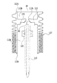
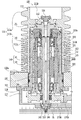
- FIG. 1 is a cross-sectional view of a gas exhaust pump according to an embodiment of the present invention.
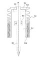
- the schematic diagram which shows the connection position of the male rotor which concerns on one Embodiment of this invention, and a rotating shaft.
- the schematic diagram which shows the connection position of the conventional rotor and a rotating shaft.
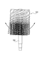
- produces in the conventional rotor.
- the screw vacuum pump 100 includes a pair of male and female rotors 110 and 120 that are arranged in mesh with each other while maintaining a meshing gap and rotate synchronously in opposite directions, A stator 130 for housing the female rotor 120, rotary shafts 150A and 150B connected to the male and female rotors 110 and 120, a drive motor 140 provided integrally with the rotary shaft 150A, and the rotary shaft 150A are rotatable.
- Bearing bearings 160, 161, 162 for supporting, a pair of synchronous gears 170A, 170B attached to the lower ends of the rotary shafts 150A, 150B, an oil reservoir 300 provided below the stator 130 and containing oil OL, It is provided at the lower end of the rotating shafts 150A and 150B.
- a shaft seal device 230 disposed above the bearing 160 and a support member 200 that supports the shaft seal device 230 are provided.
- FIG. 1 details of the structure inside the female rotor 120 are omitted, but a bearing is also provided on the female rotor 120 side in the same manner as the male rotor 110, and the rotary shaft 150B is rotatably supported.
- the same shaft seal device and support member as those on the male rotor 110 side are provided, but no drive motor is provided.
- a drive motor may be integrally provided on the rotating shaft 150B on the female rotor side (in this case, for example, it is rotated so as to be synchronized using an inverter). It is also possible to make the configuration of the female rotor side shaft sealing device, the support member, etc. different from that of the male rotor 110 side.
- the stator 130 is made of a metal such as stainless steel. As shown in FIG. 1, the stator 130 is fixed to the main body 131 that houses the male rotor 110 and the female rotor 120, the lower end of the main body 131, and the exhaust port 136.
- the stator 130, the male rotor 110, and the female rotor 120 cooperate to form a gas working chamber that transfers and compresses gas.
- the male rotor 110 and the female rotor 120 respectively have screw teeth 111 and 121 that mesh with each other while maintaining a meshing gap.
- the screw teeth 111 and 121 of the male rotor 110 and the female rotor 120 are disposed on the intake port 135 side, and are unequal lead unequal inclination angle screw portions (hereinafter referred to as unequal lead screw portions) 111a for transporting and compressing gas.
- unequal lead screw portions unequal lead screw portions
- the equal lead screw portions 111b and 121b are formed with equal lead equal inclination angles and have straight tooth traces.
- the unequal lead screw portions 111a and 121a are formed such that the lead and the inclination angle (lead angle) gradually decrease from the intake port 135 side to the exhaust port 136 side, and have curved tooth traces. .
- the lead angle changes according to the rotation angles of the male rotor 110 and the female rotor 120, and between one lead of the gas working chamber formed by the male rotor 110 and the female rotor 120 and the stator 130. Is continuously reduced from the intake port 135 side toward the exhaust port 136 side, whereby gas transfer compression is performed.
- the rotary shaft 150A is formed of a metal such as stainless steel, and the upper end side is rotatably supported by the support member 200 via the bearing 160 and is coaxially connected to the male rotor 110.
- the structure of the support member 200 will be described later.
- Bearings 161 and 162 are provided on the lower end side of the rotating shaft 150 ⁇ / b> A.
- the bearing 161 is held by a first bearing holder 137 and the bearing 162 is held by a second bearing holder 138.
- the first bearing holder 137 is fixed to the lower end portion of the support member 200, and the second bearing holder 138 is fixed to the base portion 132.
- the bearing 160 is an angular ball bearing and supports most of the loads of the male rotor 110 and the rotating shaft 150A.
- the bearings 161 and 162 are also angular ball bearings, these are mainly provided to suppress the swing of the rotating shaft 150 ⁇ / b> A that may occur during the high-speed rotation of the male rotor 110.
- the lubrication of the bearings 160 to 162 will be described later.
- the drive motor 140 includes a motor rotor 141 fixed between the bearings 160 and 161 of the rotary shaft 150A, and a stator 142 disposed around the motor rotor 141 and fixed to the support member 220 so that a predetermined gap 143 is formed. It is driven by receiving AC power from the outside of the pump.
- FIG. 3 is a schematic diagram showing the relationship between a conventional male rotor and a rotating shaft.
- the rotor 510 shown in FIG. 3 is the same as the male rotor 110 with respect to the screw teeth on the outer peripheral side, but a hollow 512 is formed at the upper end 510t with a connecting portion 512 to the rotary shaft 550 and opens at the lower end surface in the rotation axis direction
- a hollow portion 511 accommodates a part 511 and a bearing 560 that rotatably supports a part of the rotation shaft 550 and the rotation shaft 550.
- This vibration deformation mode is an axial bending deformation with the bearing 560 as a restraint portion as a base point.
- the structure shown in FIG. 2 is adopted in order to increase the resonance frequency of the rotor.
- the male rotor 110 has a lower hollow portion 113A that opens at the lower end surface 110b in the direction of the rotation axis AX, and an upper hollow portion 113B that opens at the upper end surface 110t.
- the hollow portion 113B communicates with the hollow portion 113B through a through hole 112h formed in the connecting portion 112.
- the connecting portion 112 is connected to a flange portion 151 formed at the upper end portion of the rotating shaft.
- the connecting portion 112 is disposed at a position away from the upper end surface 110 t and the lower end surface 110 b of the male rotor 110, and the rotation axis AX direction of the connecting portion 112 is located near the center of gravity GC of the male rotor 110. In this way, the connection position between the rotary shaft 150 and the male rotor 110 is moved to the position of the center of gravity GC of the male rotor 110, and the distance between the bearing 160 serving as the restraint portion and the connection portion between the rotary shaft 150 and the male rotor 110 is set. It was found that the resonance frequency of the male rotor 110 can be increased by shortening the length compared to the conventional one.
- the primary resonance point of the male rotor 110 could be increased to over 10,000 rpm. Further, by connecting the rotating shaft 150 and the male rotor 110 to the inside of the male rotor 110, the entire length of the rotating shaft 150 can be shortened as compared with the conventional one, and weight reduction, vibration suppression, and the like can be achieved. But it is advantageous. Although only the male rotor 110 has been described, the same structure is adopted for the female rotor 120.
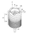
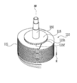
- a plurality of end surface portions 114 formed at the end of the unequal lead screw portion 111 a on the upper end side of the male rotor 110 are used as masses for adjusting the rotational balance of the male rotor 110.
- a plurality of mass attaching portions 114h for attaching the screw M are arranged.
- the mass attaching part 114h is configured by, for example, a screw hole.
- the end surface portions 114 are arranged at equal intervals in the circumferential direction around the rotation axis AX, and are orthogonal to the rotation axis AX.
- the plurality of mass attaching portions 114h are arranged along the circumferential direction, and are also arranged at equal intervals in the radial direction.
- a disk-shaped plate 115 is formed integrally with the male rotor 110 at the lower end of the male rotor 110.
- the center of the disk-shaped plate 115 coincides with the rotation axis AX, and the outer peripheral surface 115f of the disk-shaped plate 115 is parallel to the rotation axis AX.
- a plurality of mass attaching portions 115h are formed on the outer peripheral surface 115f at regular intervals along the circumferential direction.
- the mass attachment portion 115h is configured by, for example, a screw hole formed toward the center of the disk-shaped plate 115.
- a screw M as a mass for adjusting the rotational balance of the male rotor 110 can be attached to the mass attaching portion 115h.
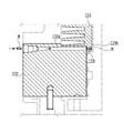
- a passage 132 a is formed in the base portion 132 of the stator 130 that allows access to the mass attaching portion 115 h from the outside of the stator 130.
- the passage 132a is normally sealed and opened only when necessary.
- the mass attaching portion 114h on the upper end side of the male rotor 110 can be accessed from the outside of the stator 130 through the air inlet 135 as shown in FIG.
- the mass attaching portions are provided at the upper and lower ends of the male rotor 110.
- the present invention is not limited to this.
- the mass attaching portions are formed in the intermediate portion in the rotation axis direction of the male rotor 110. It is also possible. Although only the male rotor 110 has been described, the same structure is adopted for the female rotor 120.
- the rotary shaft 150 ⁇ / b> A has an oil supply path 152 formed by a through hole extending in the longitudinal direction at the center thereof.
- the opening at the lower end surface of the through hole formed in the rotating shaft 150A is an inlet 153 into which the oil OL flows, and the opening at the upper end surface of the through hole is a plug fixed to the connecting portion 112 of the male rotor 110. It is sealed with a member 156.
- a member 156 As shown in an enlarged view in FIG.
- the oil supply path 152 communicates with an oil supply path 152 a extending in the radial direction of the rotary shaft 150 ⁇ / b> A formed above the bearing 160, and the outer periphery of the rotary shaft 150 ⁇ / b> A.
- the end of the oil supply path 152a that opens at the surface is an outlet 154 from which the oil OL flows out.
- the oil supply path 152a is formed at two positions symmetrical with respect to the rotation axis AX, and each oil supply path 152a has a flow path 155h having a flow path area defined so as to adjust the flow rate of the oil OL to a predetermined amount.
- the flow rate adjusting member 155 formed with is screwed.
- a push-up head 180 that pushes oil OL upward from the oil reservoir 300 by centrifugal force and drag effect is provided at the inlet 153 of the rotary shaft 150A.
- the push-up head 180 has a through-hole penetrating in the vertical direction, and the inner peripheral surface of the through-hole is formed in a tapered shape that increases in diameter from below to above.
- the push-up head 180 is fixed to the lower end of the rotary shaft 150A, and rotates with the rotary shaft 150A when the screw vacuum pump 100 is driven.
- the centrifugal force using the tapered inner peripheral surface and the rotation of the rotary shafts 150A and 150B described above.
- the lubricating oil is pushed up from the oil reservoir 300 by a drag effect.
- the oil OL pushed up by the rotating push-up head 180 moves upward along the inner wall of the oil supply path 152 and is discharged from the outlet 154 to the outside of the rotary shaft 150A through the oil supply path 152a and the flow rate adjusting member 155. Is done.
- an annular oil amount adjusting ring 220 is provided between the bearing 160 of the rotation shaft 150A and the outlet 154.
- the oil amount adjusting ring 220 is fixed to the rotating shaft 150A.
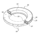
- the oil amount adjusting ring 220 includes an annular lower plate portion 221, an annular upper plate portion 222 facing the lower plate portion 221, and a lower plate portion 221 and an upper plate portion 222 on the inner peripheral side.
- the connecting wall 223 is formed with a flow hole 225 formed at a position corresponding to the outlet 154 of the oil supply passage 152a extending in the radial direction of the rotary shaft 150A.
- a plurality of oil supply holes 226 that supply oil OL for lubricating the bearing 160 are arranged in the lower plate portion 221 at equal intervals along the circumferential direction.
- a flange part 24 is formed on the upper part of the outer periphery of the lower plate part 221. The flange 24 serves to prevent the oil OL from falling downward from between a receiving plate 210 (described later) fitted into the outer peripheral surface 228 of the lower plate 221 and the lower plate 221.
- the oil amount adjustment ring 220 is provided above the bearing 160 to optimize the supply amount of the oil OL.
- the number and dimensions of the oil supply holes 226 of the oil amount adjustment ring 220 are adjusted in advance so that the supply amount of the oil OL is optimized.
- the oil amount adjusting ring 220 is not limited to the oil amount adjusting mechanism of the present invention. Further, although the oil amount adjusting ring 220 is fixed to the rotating shaft 150A, an oil amount adjusting mechanism can be realized without being fixed to the rotating shaft 150A.
- the receiving plate 210 is formed in an annular shape, covers the upper portion of the bearing 160 together with the oil amount adjusting ring 220, and is fixed to the support member 200.
- the receiving plate 210 is provided to guide oil OL discharged from the outlet 154 of the rotary shaft 150A to a plurality of inlets 201a and 202a formed in the support member 200 described later.
- a circulation hole 210h is formed at a position corresponding to 201a and 202a.
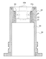
- the support member 200 is formed of a metal such as stainless steel and is formed in a cylindrical shape as shown in FIGS. 9A and 9B. As shown in FIG. 1, the support member 200 is formed in the cylindrical hollow portion 113A of the male rotor 110. A slight gap is formed between the outer peripheral surface 206 of the support member 200 and the inner wall surface of the hollow portion 113A.
- the support member 200 has a lower end fixed to the base portion 132 of the stator 130, and extends in the direction of the rotation axis AX so as to reach the middle of the unequal lead screw portion 111a from the base portion 132 through the opening of the hollow portion 113A. It is extended.
- the support member 200 is transmitted with heat from the male rotor 110 that becomes high temperature due to the compression heat of the gas.
- the male rotor 110 is expected to have the highest temperature at the end portion of the unequal lead screw portion 111a on the side of the equal lead screw portion 111b.
- the heat of the male rotor 110 is increased. Can be received effectively.
- the support member 200 holds the bearing 160 in the bearing holding portion 203, the heat generated by the bearing 160 can be effectively received.
- a plurality of first flow paths 201 and a plurality of second flow paths 202 are formed on the outer peripheral side of the bearing holding portion 203 through which oil OL extending in the vertical direction flows.
- the first flow path 201 is formed so as to distribute the oil OL flowing from the inflow port 201 a to the gap 143 formed between the motor rotor 141 and the motor stator 142 of the drive motor 140.
- the second flow path 202 is formed so as to distribute the oil OL flowing from the inlet 202 a onto the outer peripheral surface 142 a of the motor stator 142. That is, the support member 200 also serves as the flow path member and the guide member of the present invention. Note that the present invention is not limited to this, and the flow path member and the guide member may be separate members.
- the motor stator 142 has a plurality of grooves 142b formed in the outer peripheral surface 142a and extending in the rotation axis direction.
- the groove 142b cooperates with the inner wall surface 205 of the support member 200 to form a flow path for circulating the oil OL supplied from the second flow path 202.
- the oil reservoir 300 is formed at a lower portion of the stator 130 and is provided for storing the oil OL.
- a cooling pipe 191 of the cooling device 190 is disposed in the oil reservoir 300.
- the cooling device 190 cools the oil OL stored in the oil reservoir 300 by a water cooling method, and is disposed in the oil reservoir 300 and circulates the cooling water, and supplies the cooling water to the cooling pipe 191.
- a cooling pump 192 is included.
- the shaft seal device 230 prevents the oil OL and its vapor supplied from the outlet 154 of the rotary shaft 150A from entering the gas working chamber formed by the stator 130, the male rotor 110, and the female rotor 120 in cooperation.
- the rotary shaft 150A is sealed.
- the shaft seal device 230 is formed in an annular shape and fixed to the upper end of the support member 200, and a first seal that holds the first lip seal 233a and the second lip seal 233b.
- the assembly 232 includes a second seal assembly 234 disposed adjacent to the first seal assembly 232 and holding the lip seal 234a, and a labyrinth seal 235 provided adjacent to the second seal assembly 234.
- the first and second lip seals 233a, 233b and the lip seal 234a that are in contact with the surface of the rotating shaft 150A are characterized by having heat resistance, chemical stability, low friction properties, and moderate elasticity. It is desirable to be composed of a fluorinated resin.
- fluorinated resins include: (1) perfluorinated resins such as polytetrafluoroethylene (PTFE), and (2) partially fluorinated resins such as polychlorotrifluoroethylene (PCTFE, CTFE). , Polyvinylidene fluoride (PVDF), polyvinyl fluoride (PVF), etc.
- fluorinated resin copolymers such as perfluoroalkoxy fluororesin (PFA), tetrafluoroethylene / hexafluoropropylene copolymer (FEP) ), Ethylene / tetrafluoroethylene copolymer (ETFE), ethylene / chlorotrifluoroethylene copolymer (ECTFE), and the like.
- PFA perfluoroalkoxy fluororesin
- FEP tetrafluoroethylene / hexafluoropropylene copolymer
- Ethylene / tetrafluoroethylene copolymer ETFE
- ECTFE ethylene / chlorotrifluoroethylene copolymer
- PFA and PTFE are particularly preferable. Since these resins can dramatically improve heat resistance by being provided on a metal such as nickel (Ni) or nickel fluoride (NiF2), such an embodiment is particularly preferable in the present invention. Is.
- the holding member 231 is provided with a seal gas supply path 231a.
- a seal gas such as nitrogen gas is supplied to the seal gas supply path 231a, and the upper end side from the gas passage 232a formed in the main body of the first seal assembly 232 is provided. And flows toward the lower end side, and is discharged through a gas passage 232b formed in the main body of the first seal assembly 232.
- the supply path and discharge path (not shown) of the seal gas are formed in the support member 200 and the stator 130, and the seal gas is supplied from the outside of the pump through this supply path and passes through the gas passage 232b. Is discharged to the outside of the pump through a discharge path (not shown) and collected by a collection device (not shown).
- the rotating shaft 150A is made of stainless steel
- PTFE may be thermally decomposed by the catalytic effect of stainless steel when the temperature rises to about 180 ° C. or higher. Therefore, in this embodiment, the oil circulation system efficiently releases the heat in the pump to the outside to suppress the temperature rise of the lip seal, but to prevent the lip seal from deteriorating and to obtain a stable sealing performance for a long period of time.
- a nickel plating film or a nickel fluoride film may be applied to the contact portion of the rotary shaft 150A between the first and second lip seals 233a, 233b and the lip seal 234a. preferable.
- the space in which the oil circulates is a sealed space and the sealed space is decompressed.
- a vacuum formed by the screw vacuum pump 100 can be used. It is also possible to provide another pump to reduce the pressure.
- the pressure reduction may be, for example, a pressure at which the saturation solubility of air is about half of the saturation solubility at atmospheric pressure.
- the oil circulation of the above oil circulation system will be described with reference to FIG.
- the screw vacuum pump 100 is driven, as shown in FIG. 11, the oil OL cooled in the oil reservoir 300 by the rotating push-up head 180 is supplied to the oil supply path 152, the oil supply path 152a and the outlet of the rotary shaft 150A.
- 154 is supplied onto the lower plate portion 221 and the receiving plate 210 of the oil amount adjusting ring 220, and a part of the oil OL is lubricated to the bearing 160 through the oil supply hole 226 of the lower plate portion 221 for lubrication of the bearing 160.
- the oil OL drops from the bearing 160 and is supplied to the gap 143 of the drive motor 140.
- the oil OL supplied onto the receiving plate 210 is distributed to the first and second flow paths 201 and 202.
- the heat generated in the bearing 160 is absorbed by the oil OL supplied directly to the bearing 160 and is absorbed by the oil OL flowing through the first and second flow paths 201 and 202 that pass around the bearing 160. .
- the oil OL flowing through the first and second flow paths 201 and 202 absorbs heat received from the rotary shaft 150A side and the male rotor 110 side, and then grooves are formed in the gap 143 of the drive motor 140 and the outer peripheral surface of the motor stator 142. It flows through the flow path formed by 142b. Thereby, the heat generated from the drive motor 140 is efficiently absorbed.
- the oil OL that has passed through the drive motor 140 falls into the oil reservoir OL, but a part of the oil OL is supplied to the meshing portions of the bearings 161 and 162 and the synchronous gears 170A and 170B for lubrication and then into the oil reservoir OL. Fall into. Although the temperature of the oil OL falling into the oil reservoir OL has risen, it is cooled to a predetermined temperature by the cooling device 190 in the oil reservoir OL. Although only the male rotor 110 has been described, a similar oil circulation system can be employed for the female rotor 120.
- the amount of oil OL that can be supplied for lubrication and cooling by the lifting head 180 is limited to some extent because it depends on the rotational speed of the lifting head 180.
- a limited amount of oil OL can be efficiently used for lubrication and cooling, and temperature rise of the screw vacuum pump 100 can be prevented. As a result, the screw vacuum pump 100 can be operated at high speed.
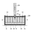
- An oil reservoir 300A shown in FIG. 12 is disposed concentrically in a closed space CS, a tank 301 formed of a heat insulating material, a bottom plate 304 provided inside the tank 301 and forming a closed space CS together with the tank 301.
- An upper part of the tank 301 has an oil outlet 302 into which the push-up head 180 is inserted and communicates with the oil supply path of the rotary shaft 150A, and an inlet 303 into which the recovered oil flows.
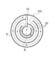
- the inflow port 303 is disposed in the outermost peripheral region R 1 of the tank 301, and the oil outflow port 302 is disposed in the central region R 2 of the tank 301.
- the cooling liquid 320 flows to the bottom of the tank 301, and the cooling liquid 320 of the cooler is in full contact with the bottom plate 304.
- the oil OL flow by the oil circulation should be designed to be a turbulent flow with about 2000 to 3000 lay nozzles. preferable. Further, it is preferable that the flow passage cross-sectional area of the oil OL is constant so that the number of lay nozzles is constant in the tank 301.
- a part of the tank 301 is formed of a flexible material, the flexible part is pressed from the outside of the tank 301 to be elastically deformed, and the volume of the closed space CS is reduced, whereby the oil OL is pushed up. Can be pushed inward.
- a plunger device 340 is provided in the tank 300 ⁇ / b> A, and an auxiliary tank 330 is connected to the inlet 303 via a backflow prevention mechanism 340.
- the rear end portion of the plunger rod 342 to which the plunger tip 341 of the plunger device 340 is connected to the tip is connected to the piston rod 361 of the cylinder device 360 so that the plunger tip 341 can reciprocate.
- the plunger tip 341 is advanced, the volume of the closed space CS decreases, and the oil OL is pushed up into the push-up head 180. At this time, the oil OL in the tank 301 does not flow back through the inflow port 303 by the backflow prevention mechanism 340. Further, when the plunger tip 341 is retracted, the oil OL recovered in the auxiliary tank 330 is present, so that the oil OL in the lifting head 180 can be prevented from returning into the oil tank 301.
- Screw vacuum pump 110 Male rotor 111 Screw tooth 111a Unequal lead Unequal inclination angle screw part 111b Equal lead screw part 111c connecting portion 113a hollow portion 113b hollow portion 114 flat plate portion 114h mounting hole 115 disk portion 115h mounting hole 120 female rotor 121 screw tooth 121a unequal lead unequal inclination angle screw portion 121b equal lead screw portion 130 Stator 135 Intake port 136 Exhaust port 140 Drive motor 141 Motor rotor 142 Motor stator 142a Outer peripheral surface 142b Channel groove 143 Gap 150 Rotating shaft 152, 152a Oil supply path 156 Blocking member 160, 161, 162 Bearing 180 Lifting head 190 Cooling Device 200 Support member 201 First channel 201a Inlet 202 Second channel 202a Inlet 210 Receiving plate 220 Oil amount adjusting ring 230 Shaft seal device 231 Holding member 232 First seal assembly 233a First lip seal 233b Second lip Seal 234 Second seal assembly 234a Lip seal 235 Labyrinth
Landscapes
- Engineering & Computer Science (AREA)
- Mechanical Engineering (AREA)
- General Engineering & Computer Science (AREA)
- Applications Or Details Of Rotary Compressors (AREA)
- Structures Of Non-Positive Displacement Pumps (AREA)
Abstract
スクリューロータの高速回転化を実現して排気速度が高められたスクリュー真空ポンプを提供する。雄ロータ(110)が連結された回転シャフト(150A)を回転自在に支持する軸受(160)が、雄ロータ(110)の中空部(113A)内に配置され、雄ロータ(110)と回転シャフト(150A)との連結部は、回転軸線(AX)方向において、中空部(113A)内の雄ロータ(110)の略重心(GC)の位置に配置されている。
Description
本発明は、スクリュー真空ポンプに関する。
一般的には、半導体デバイス、液晶や有機EL等を使用する表示デバイス、太陽電池デバイス等の機能デバイスを製造する製造装置や生産システムにおいては、ポンプ性能による適用範囲の限度から多種多様のポンプが数多く使用される。これに対して、例えば、特許文献1~3に開示されたようなタイプのスクリュー真空ポンプは、分子流域から粘性流域まで広範囲の排気が可能で排気性能が排気ガス種に依存しない。このため、ガス種毎にポンプを替える、圧力条件の変化に対応してポンプを据え代る、複数の排出箇所を有する生産システムにおける排出箇所毎に適したポンプを用意する、といった煩雑さを招くこともない。排気速度に依存しなければ同一種のポンプを使用すればよく、いちいち排気箇所毎にポンプを選定する煩わしさは生じない。仮に、上記タイプのポンプにおいて低コスト化が実現して商業化されれば、その普及度は著しいものになり、産業の発展に大いに貢献することが容易に予想される。
上記タイプのポンプでは、できるだけ高速にスクリューロータを回転させることができれば、ポンプを小型化しつつ高排気速度化を実現できる。スクリューロータの回転を高速化すると、数千rpm~一万rpmのような目標回転数に達する前に、スクリューロータに許容できない振動が発生してしまう。
本発明の目的の一つは、スクリューロータの高速回転化を実現して排気速度が高められたスクリュー真空ポンプを提供することにある。
本発明のもう一つの目的は、高速運転に於いて振動が発生しても許容範囲内の振動に留めることが可能で静粛安定運転に優れたスクリュー真空ポンプを提供することにある。
本発明のもう一つの目的は、高速運転に於いて振動が発生しても許容範囲内の振動に留めることが可能で静粛安定運転に優れたスクリュー真空ポンプを提供することにある。
本発明の第1の観点のスクリュー真空ポンプは、互いに噛み合うスクリュー歯を有する雄ロータおよび雌ロータを有し、
前記雄ロータ及び雌ロータのスクリュー歯部は、回転軸線方向の上端側に形成された不等リード不等傾斜角スクリュー部と、回転軸線方向の下端側に形成された前記不等リード不等傾斜角スクリュー部に連続する等リードスクリュー部とを有し、
前記雄ロータおよび雌ロータの少なくとも一方のロータは、回転軸線方向の上端面および下端面で開口する中空部を有し、
前記少なくとも一方のロータに連結されるとともに前記中空部に少なくとも一部が収容された回転シャフトを有し、
前記中空部内に収容され、前記回転シャフトを回転自在に支持する軸受を有し、
前記少なくとも一方のロータと前記回転シャフトとの連結部は、回転軸線方向において、前記少なくとも一方のロータの重心の位置付近に配置されている、ことを特徴とする。
本発明の第2の観点のスクリュー真空ポンプは、互いに噛み合うスクリュー歯を有する雄ロータおよび雌ロータを有し、
前記雄ロータおよび雌ロータの少なくとも一方のロータは、回転軸線方向の上端面および下端面で開口する中空部を有し、
前記少なくとも一方のロータに連結されるとともに前記中空部に少なくとも一部が収容された回転シャフトを有し、
前記中空部内に収容され、前記回転シャフトを回転自在に支持する軸受を有し、
前記少なくとも一方のロータと前記回転シャフトとの連結部は、前記少なくとも一方のロータの上端部および下端部から離れた前記中空部内に配置されている、ことを特徴とする。
前記雄ロータおよび雌ロータの少なくとも一方のロータは、回転軸線方向の上端面および下端面で開口する中空部を有し、
前記少なくとも一方のロータに連結されるとともに前記中空部に少なくとも一部が収容された回転シャフトを有し、
前記中空部内に収容され、前記回転シャフトを回転自在に支持する軸受を有し、
前記少なくとも一方のロータと前記回転シャフトとの連結部は、前記少なくとも一方のロータの上端部および下端部から離れた前記中空部内に配置されている、ことを特徴とする。
本発明の第3の観点のスクリュー真空ポンプは、互いに噛み合うスクリュー歯を有する雄ロータおよび雌ロータを有し、
前記雄ロータ及び雌ロータのスクリュー歯部は、不等リード不等傾斜角スクリュー部と、前記不等リード不等傾斜角スクリュー部に連続する等リードスクリュー部とを有し、
気体の吸気口及び吐出口を備えるとともに前記雄ロータおよび雌ロータを収容するステータを有し、
前記雄ロータおよび雌ロータの少なくとも一方のロータは、回転軸線方向の下端面で開口する中空部を有し、
前記少なくとも一方のロータに連結されるとともに前記中空部に少なくとも一部が収容された回転シャフトを有し、
前記中空部内に収容され、前記回転シャフトを回転自在に支持する軸受を有し、
前記少なくとも一方のロータは、前記少なくとも一方のロータ回転バランスを調整するための質量を取り付けるための複数のマス取付け部を有し、
前記ステータは、当該ステータの外部から前記複数のマス取付け部にアクセス可能に形成されている、ことを特徴とする。
本発明によれば、高速回転により生じる振動を抑制でき、高速回転化されて排気速度が高められたスクリュー真空ポンプが提供される。
以下に添付図面を参照しながら、本発明の実施形態について詳細に説明する。なお、本明細書及び図面において、実質的に同一の機能構成を有する構成要素については、同一の符号を付することにより重複説明を省略する。
第1実施形態
図1~図11を参照して、本発明の第1の実施形態に係るスクリュー真空ポンプについて説明する。先ず、スクリュー真空ポンプの基本構成について説明する。スクリュー真空ポンプ100は、図1に示すように、噛み合い隙間を保ちつつ相互に噛み合った状態で配置されて逆方向に同期して回転する一対の雄ロータ110及び雌ロータ120と、雄ロータ110及び雌ロータ120を収納するステータ130と、雌雄のロータ110,120にそれぞれ連結された回転シャフト150A,150Bと、回転シャフト150Aに一体的に設けられた駆動モータ140と、回転シャフト150Aを回転自在に支持する軸受ベアリング160,161,162と、回転シャフト150A、150Bの下端部に取り付けられた一対の同期ギア170A,170Bと、ステータ130の下方に設けられてオイルOLを収容するオイルリザーバ300と、回転シャフト150A、150Bの下端部に設けられて回転シャフト150A、150Bの回転を利用して遠心力によりオイルリザーバ300内のオイルOLを押し上げるための押上げヘッド180と、オイルリザーバ300に収容されたオイルOLを水冷式で冷却する冷却装置190と、軸受160の上方に配置された軸封装置230と、軸封装置230を支持するサポート部材200と、を備える。
図1~図11を参照して、本発明の第1の実施形態に係るスクリュー真空ポンプについて説明する。先ず、スクリュー真空ポンプの基本構成について説明する。スクリュー真空ポンプ100は、図1に示すように、噛み合い隙間を保ちつつ相互に噛み合った状態で配置されて逆方向に同期して回転する一対の雄ロータ110及び雌ロータ120と、雄ロータ110及び雌ロータ120を収納するステータ130と、雌雄のロータ110,120にそれぞれ連結された回転シャフト150A,150Bと、回転シャフト150Aに一体的に設けられた駆動モータ140と、回転シャフト150Aを回転自在に支持する軸受ベアリング160,161,162と、回転シャフト150A、150Bの下端部に取り付けられた一対の同期ギア170A,170Bと、ステータ130の下方に設けられてオイルOLを収容するオイルリザーバ300と、回転シャフト150A、150Bの下端部に設けられて回転シャフト150A、150Bの回転を利用して遠心力によりオイルリザーバ300内のオイルOLを押し上げるための押上げヘッド180と、オイルリザーバ300に収容されたオイルOLを水冷式で冷却する冷却装置190と、軸受160の上方に配置された軸封装置230と、軸封装置230を支持するサポート部材200と、を備える。
図1において、雌ロータ120内の構造の詳細が省略されているが、雌ロータ120側にも、雄ロータ110と同様に軸受が設けられており、回転シャフト150Bは回転自在に支持されており、雄ロータ110側と同様の軸封装置、サポート部材等を備えているが、駆動モータは設けられていない。なお、本発明はこれに限定されるわけではなく、雌ロータ側の回転シャフト150Bに駆動モータを一体的に設けてもよいし(この場合には、例えば、インバータを用いて同期するように回転制御される。)、また、雌ロータ側の軸封装置、サポート部材等の構成を雄ロータ110側と異ならせることも可能である。
ステータ130は、ステンレス鋼等の金属で形成され、図1に示すように、雄ロータ110及び雌ロータ120を収納する本体部131と、本体部131の下端部に固定されるとともに排気口136が形成されたベース部132と、本体部131の上端側を覆うエンドプレート133と、エンドプレート133に固定されて吸気口135を画定する吸気口部134とを有する。
ステータ130と雄ロータ110と雌ロータ120とは、協働して、ガスを移送圧縮する気体作動室を形成する。雄ロータ110及び雌ロータ120は、噛み合い隙間を保ちつつ相互に噛み合うスクリュー歯111、121を外周側にそれぞれ有している。これら雄ロータ110及び雌ロータ120のスクリュー歯111、121は、吸気口135側に配置されて、ガスを移送圧縮する不等リード不等傾斜角スクリュー部(以下、不等リードスクリュー部という)111a、121aと、不等リードスクリュー部111a、121aに連続し、ガスを移送する等リードスクリュー部111b、121bとを有している。等リードスクリュー部111b、121bは、等リード等傾斜角で形成されて、直線の歯筋を有している。不等リードスクリュー部111a、121aは、吸気口135側から排気口136側に向けてリードおよび傾斜角(リード角)が徐々に小さくなるように形成されて、曲線の歯筋を有している。この不等リードスクリュー部111a、121aでは、リード角が雄ロータ110及び雌ロータ120の回転角にしたがって変化し、雄ロータ110及び雌ロータ120とステータ130により形成される気体作動室の1リード間の容積が吸気口135側から排気口136側に向けて連続的に減少することで、ガスの移送圧縮が行われる。
回転シャフト150Aは、ステンレス鋼等の金属で形成され、上端部側を、軸受160を介してサポート部材200により回転自在に支持され、雄ロータ110と同軸状に連結されている。サポート部材200の構造については後述する。回転シャフト150Aの下端部側には、軸受161および162が設けられており、軸受161は第1軸受ホルダ137、軸受162は第2軸受ホルダ138により保持されている。第1軸受ホルダ137は、サポート部材200の下端部に固定され、第2軸受ホルダ138は、ベース部132に固定されている。
軸受160は、アンギュラー玉軸受であり、雄ロータ110および回転シャフト150Aの荷重の大部分を支持している。軸受161,162もアンギュラー玉軸受であるが、これらは、主に、雄ロータ110の高速回転中に発生する可能性のある回転シャフト150Aの振れを抑制するために設けられている。なお、軸受160~162の潤滑については後述する。
駆動モータ140は、回転シャフト150Aの軸受160と161の間に固定されたモータロータ141と、所定のギャップ143が形成されるようにモータロータ141の周囲に配置されかつサポート部材220に固定されたステータ142を有し、ポンプの外部から交流電力を受けることにより駆動される。
振動抑制構造
ここで、雌雄のロータの高速回転時に発生する振動の抑制のための構造について説明する。図3は、従来の雄ロータと回転シャフトの関係を示す模式図である。図3に示すロータ510は、外周側のスクリュー歯については雄ロータ110と同じであるが、上端部510tに回転シャフト550との連結部512が形成され、回転軸線方向の下端面で開口する中空部511を有し、回転シャフト550の一部および回転シャフト550を回転自在に支持する軸受560が中空部511に収容されている。
ここで、雌雄のロータの高速回転時に発生する振動の抑制のための構造について説明する。図3は、従来の雄ロータと回転シャフトの関係を示す模式図である。図3に示すロータ510は、外周側のスクリュー歯については雄ロータ110と同じであるが、上端部510tに回転シャフト550との連結部512が形成され、回転軸線方向の下端面で開口する中空部511を有し、回転シャフト550の一部および回転シャフト550を回転自在に支持する軸受560が中空部511に収容されている。
このロータ510を高速回転させると、7000rpm近辺に1次の共振点が存在し、図4に示すような振動が発生することが判明した。この振動の変形モードは、拘束部である軸受560を基点とする軸曲げ変形である。
本発明では、ロータの共振周波数を高めるために、図2に示す構造を採用している。図2に示すように、雄ロータ110は、回転軸線AX方向の下端面110bで開口する下側中空部113Aと上端面110tで開口する上側中空部113Bを有し、下側中空部113Aと上側中空部113Bとは、連結部112に形成された貫通孔112hを介して連通している。連結部112は、回転シャフトの上端部に形成されたフランジ部151に連結される。この連結部112は、雄ロータ110の上端面110tおよび下端面110bから離れた位置に配置されており、連結部112の回転軸線AX方向は、雄ロータ110の重心GCの付近に位置する。このように、回転シャフト150と雄ロータ110との連結位置を雄ロータ110の重心GCの位置に移動させ、拘束部である軸受160と回転シャフト150および雄ロータ110との連結部との距離を従来と比べて短縮化することで、雄ロータ110の共振周波数を高めることができることがわかった。具体的には、雄ロータ110の1次の共振点を10000rpm超に高めることができた。また、回転シャフト150と雄ロータ110との連結位置を雄ロータ110の内部とすることで、回転シャフト150の全長を従来と比較して短縮化することができ、軽量化、振動抑制等の点でも有利となる。なお、雄ロータ110についてのみ説明したが、雌ロータ120についても同様の構造が採用される。
バランス調整機構
次に、本実施形態に係るスクリュー真空ポンプのバランス調整機構について説明する。図5Aに示すように、雄ロータ110の上端側にある、不等リードスクリュー部111aの終端に形成された複数の端面部114には、雄ロータ110の回転バランスを調整するための質量としてのねじMを取り付けるための複数のマス取付け部114hが配置されている。マス取付け部114hは、例えば、ねじ穴で構成される。端面部114は、回転軸線AXを中心とする円周方向に等間隔に配置され、回転軸線AXに対して直交している。複数のマス取付け部114hは、周方向に沿って配列されているとともに、半径方向にも等間隔に配列されている。雄ロータ110の下端には、図5Bに示すように、円盤状プレート115が雄ロータ110に一体的に形成されている。円盤状プレート115の中心は、回転軸線AXに一致しており、円盤状プレート115の外周面115fは、回転軸線AXに平行である。この外周面115fに、複数のマス取付け部115hが周方向に沿って等間隔に形成されている。マス取付け部115hは、例えば、円盤状プレート115の中心に向けて形成されたねじ穴で構成される。マス取付け部115hには、雄ロータ110の回転バランスを調整するための質量としてのねじMが取り付け可能である。
次に、本実施形態に係るスクリュー真空ポンプのバランス調整機構について説明する。図5Aに示すように、雄ロータ110の上端側にある、不等リードスクリュー部111aの終端に形成された複数の端面部114には、雄ロータ110の回転バランスを調整するための質量としてのねじMを取り付けるための複数のマス取付け部114hが配置されている。マス取付け部114hは、例えば、ねじ穴で構成される。端面部114は、回転軸線AXを中心とする円周方向に等間隔に配置され、回転軸線AXに対して直交している。複数のマス取付け部114hは、周方向に沿って配列されているとともに、半径方向にも等間隔に配列されている。雄ロータ110の下端には、図5Bに示すように、円盤状プレート115が雄ロータ110に一体的に形成されている。円盤状プレート115の中心は、回転軸線AXに一致しており、円盤状プレート115の外周面115fは、回転軸線AXに平行である。この外周面115fに、複数のマス取付け部115hが周方向に沿って等間隔に形成されている。マス取付け部115hは、例えば、円盤状プレート115の中心に向けて形成されたねじ穴で構成される。マス取付け部115hには、雄ロータ110の回転バランスを調整するための質量としてのねじMが取り付け可能である。
マス取付け部114hおよびマス取付け部115hに選択的にねじMを取り付けることで、雄ロータ110単体の回転バランスを調整することはもちろん可能であるが、ここで重要なことは、スクリュー真空ポンプ100を組み立てた後に、これらマス取付け部114hおよびマス取付け部115hにアクセス可能となっていることである。回転に関与する各構成部品のバランスをとったとしても、スクリュー真空ポンプ100を組み立てた後に、回転系が確実にバランスしているとは限らず、回転バランスの調整がさらに必要な場合がある。このため、本発明では、図6に示すように、ステータ130のベース部132に、ステータ130の外部からマス取付け部115hへのアクセスを可能にする通路132aが形成されている。通路132aは、通常は密封され、必要な場合にのみ開放される。雄ロータ110の上端側のマス取付け部114hは、図1に示したように、吸気口135を通じてステータ130の外部からアクセス可能である。なお、本実施形態では、マス取付け部を雄ロータ110の上下端に設けたが、これに限定されるわけではなく、例えば、雄ロータ110の回転軸線方向の中間部にマス取付け部を形成することも可能である。なお、雄ロータ110についてのみ説明したが、雌ロータ120についても同様の構造が採用される。
オイル循環システム
次に、オイル循環システムについて説明する。なお、雄ロータ110側のオイル循環システムについてのみ説明するが、雌ロータ120側についても同様の構造が採用可能である。図1に示したように、回転シャフト150Aは、その中心部を長手方向に延在する貫通孔により形成されたオイル供給路152を有する。回転シャフト150Aに形成された貫通孔の下端面の開口が、オイルOLが流入する流入口153となっており、貫通孔の上端面の開口は、雄ロータ110の連結部112に固定された栓部材156で密閉されている。ここで、図7に拡大して示すように、オイル供給路152は、軸受160の上方に形成された回転シャフト150Aの半径方向に延びるオイル供給路152aと連通しており、回転シャフト150Aの外周面で開口するオイル供給路152aの終端が、オイルOLが流出する流出口154となっている。オイル供給路152aは、回転軸線AXに関して対称な位置の2箇所に形成され、各オイル供給路152aには、オイルOLの流量を所定量に調整するように規定された流路面積の流路155hが形成された流量調整部材155がねじ込まれている。
次に、オイル循環システムについて説明する。なお、雄ロータ110側のオイル循環システムについてのみ説明するが、雌ロータ120側についても同様の構造が採用可能である。図1に示したように、回転シャフト150Aは、その中心部を長手方向に延在する貫通孔により形成されたオイル供給路152を有する。回転シャフト150Aに形成された貫通孔の下端面の開口が、オイルOLが流入する流入口153となっており、貫通孔の上端面の開口は、雄ロータ110の連結部112に固定された栓部材156で密閉されている。ここで、図7に拡大して示すように、オイル供給路152は、軸受160の上方に形成された回転シャフト150Aの半径方向に延びるオイル供給路152aと連通しており、回転シャフト150Aの外周面で開口するオイル供給路152aの終端が、オイルOLが流出する流出口154となっている。オイル供給路152aは、回転軸線AXに関して対称な位置の2箇所に形成され、各オイル供給路152aには、オイルOLの流量を所定量に調整するように規定された流路面積の流路155hが形成された流量調整部材155がねじ込まれている。
図1に戻って、回転シャフト150Aの流入口153には、オイルリザーバ300からオイルOLを遠心力及びドラッグ効果により上方へ押し上げる押し上げヘッド180が設けられている。押し上げヘッド180は、上下方向に貫通する貫通孔を有し、この貫通孔の内周面は、下方から上方に向けて拡径するテーパ状に形成されている。押し上げヘッド180は、回転シャフト150Aの下端に固定され、スクリュー真空ポンプ100の駆動時には、回転シャフト150Aと共に回転し、前述したテーパ状の内周面及び回転シャフト150A、150Bの回転を利用した遠心力と、ドラッグ効果とにより、オイルリザーバ300から潤滑オイルを押し上げるように構成されている。回転する押し上げヘッド180により押し上げられたオイルOLは、オイル供給路152の内壁を伝って上方に向けて移動し、オイル供給路152aおよび流量調整部材155を通じて流出口154から回転シャフト150Aの外部へ吐出される。
オイル量調整機構
図7に戻ると、回転シャフト150Aの軸受160と流出口154との間に、環状のオイル量調整リング220が設けられている。オイル量調整リング220は、回転シャフト150Aに固定されている。オイル量調整リング220は、図8に示すように、環状の下板部221、下板部221に対向する環状の上板部222、下板部221と上板部222とを内周側で連結する連結壁部223とを有する。連結壁部223には、回転シャフト150Aの半径方向に延びるオイル供給路152aの流出口154と対応する位置に形成された流通孔225が形成されている。下板部221には、軸受160に潤滑するためのオイルOLを供給する複数のオイル供給孔226が周方向に沿って等間隔に配列されている。下板部221の外周の上部には、鍔部24が形成されている。鍔部24は、下板部221の外周面228に嵌め込まれる後述する受止め板210と下板部221との間からオイルOLが下方へ落下するのを防ぐ役割を果たす。
図7に戻ると、回転シャフト150Aの軸受160と流出口154との間に、環状のオイル量調整リング220が設けられている。オイル量調整リング220は、回転シャフト150Aに固定されている。オイル量調整リング220は、図8に示すように、環状の下板部221、下板部221に対向する環状の上板部222、下板部221と上板部222とを内周側で連結する連結壁部223とを有する。連結壁部223には、回転シャフト150Aの半径方向に延びるオイル供給路152aの流出口154と対応する位置に形成された流通孔225が形成されている。下板部221には、軸受160に潤滑するためのオイルOLを供給する複数のオイル供給孔226が周方向に沿って等間隔に配列されている。下板部221の外周の上部には、鍔部24が形成されている。鍔部24は、下板部221の外周面228に嵌め込まれる後述する受止め板210と下板部221との間からオイルOLが下方へ落下するのを防ぐ役割を果たす。
ここで、オイル量調整リング220を設けた理由について説明する。雄ロータ110および回転シャフト150Aの荷重を回転自在に支持する軸受160には、高速回転中に潤滑のためのオイルOLを供給する必要があるが、この供給量が過剰であると、軸受160から発生する熱が増大してしまうことが判明した。このため、本発明では、軸受160の上方にオイル量調整リング220を設けて、オイルOLの供給量を最適化している。オイル量調整リング220のオイル供給孔226は、オイルOLの供給量が最適になるように、その数および寸法があらかじめ調整されている。なお、オイルOLの供給量の微調整が必要な場合には、例えば、必要な数のオイル供給孔226だけを残して、不要なオイル供給孔226を金属板等で塞ぐことで対応できる。なお、オイル量調整リング220は、本発明のオイル量調整機構はこれに限定されるわけではない。また、オイル量調整リング220は、回転シャフト150Aに固定されているが、回転シャフト150Aに固定せずにオイル量調整機構を実現することも可能である。
図7において、受止め板210は、環状に形成され、軸受160の上部をオイル量調整リング220とともに覆うとともに、サポート部材200に固定されている。受止め板210は、回転シャフト150Aの流出口154から吐出されたオイルOLを、後述するサポート部材200に形成された複数の流入口201a,202aに導くために設けられており、複数の流入口201a,202aに対応する位置に流通孔210hが形成されている。
サポート部材200は、ステンレス鋼等の金属で形成され、図9A,9Bに示すように、円筒状に形成されており、図1に示したように、雄ロータ110の円筒状の中空部113A内に配置され、サポート部材200の外周面206と中空部113Aの内壁面との間には、僅かな隙間が形成されるようになっている。また、サポート部材200は、下端部がステータ130のベース部132に固定され、ベース部132から、中空部113Aの開口を通じて、不等リードスクリュー部111aの途中まで達するように回転軸線AXの方向に延在している。このような配置により、サポート部材200は、気体の圧縮熱により高温になる雄ロータ110からの熱が伝達される。特に、雄ロータ110は、不等リードスクリュー部111aの等リードスクリュー部111b側の終端部で最も高温になると予想されるが、この近くにサポート部材200を配置することで、雄ロータ110の熱を効果的に受けることができる。また、サポート部材200は、軸受保持部203に軸受160を保持しているので、軸受160で発生する熱も効果的に受けることができる。軸受保持部203の外周側には、上下方向に延びるオイルOLが流通する、複数の第1流路201および複数の第2流路202が形成されている。第1流路201は、流入口201aから流入するオイルOLを駆動モータ140のモータロータ141とモータステータ142との間に形成される空隙143へ分配するように形成されている。第2流路202は、流入口202aから流入するオイルOLをモータステータ142の外周面142a上に分配するように形成されている。すなわち、サポート部材200は、本発明の流路部材およびガイド部材を兼ねている。なお、本発明は、これに限定されるわけではなく、流路部材およびガイド部材を別部材とすることも可能である。
モータステータ142は、図10に示すように、外周面142aに形成された、回転軸線方向に延びる複数の溝部142bを有する。この溝部142bは、サポート部材200の内壁面205と協働して、第2流路202から供給されるオイルOLを流通させるための流路を形成する。
オイルリザーバ300は、図1に示すように、ステータ130の下部に形成され、オイルOLを貯留するために設けられ、オイルリザーバ300内には、冷却装置190の冷却パイプ191が配置されている。冷却装置190は、オイルリザーバ300に貯留されたオイルOLを水冷式で冷却するものであり、オイルリザーバ300内に配置され冷却水を循環させる冷却パイプ191と、冷却パイプ191に冷却水を供給する冷却ポンプ192を有する。
軸封装置230は、回転シャフト150Aの流出口154から供給されるオイルOLおよびその蒸気が、ステータ130と雄ロータ110と雌ロータ120とが協働して形成する気体作動室に侵入しないように回転シャフト150Aをシールしている。軸封装置230は、図7に示すように、環状に形成されてサポート部材200の上端部に固定された保持部材231と、第1リップシール233aおよび第2リップシール233bを保持する第1シールアセンブリ232と、第1シールアセンブリ232に隣接して配置されかつリップシール234aを保持する第2シールアセンブリ234と、第2シールアセンブリ234に隣接して設けられたラビリンスシール235とを有する。回転シャフト150Aの表面に接触する第1および第2リップシール233a,233bと、リップシール234aは、耐熱性,化学的安定性,低摩擦性、適度な弾性を有することを特徴とし、好ましくは、フッ素化樹脂で構成されるのが望ましい。
その様なフッ素化樹脂の例としては、(1)完全フッ素化樹脂、例えば、ポリテトラフルオロエチレン (PTFE)等、(2)部分フッ素化樹脂、例えば、ポリクロロトリフルオロエチレン(PCTFE,CTFE)、 ポリフッ化ビニリデン(PVDF)、ポリフッ化ビニル(PVF)等、(3)フッ素化樹脂共重合体、例えば、ペルフルオロアルコキシフッ素樹脂(PFA)、四フッ化エチレン・六フッ化プロピレン共重合体(FEP)、エチレン・四フッ化エチレン共重合体(ETFE),エチレン・クロロトリフルオロエチレン共重合体(ECTFE)等、等々のフッ素化樹脂が挙げられる。これらの中で、PFA,PTFEが特に好ましい。
これらの樹脂は、ニッケル(Ni)、フッ化ニッケル(NiF2)等の金属上に設けることで耐熱性を飛躍的に向上させることが出来るので、本発明に於いてはこのような態様は特に好ましいものである。
保持部材231には、シールガス供給路231aが形成され、このシールガス供給路231aには窒素ガス等のシールガスが供給され、第1シールアセンブリ232の本体に形成されたガス通路232aから上端側および下端側に向けて流れ、第1シールアセンブリ232の本体に形成されたガス通路232bを通じて排出される。なお、シールガスの供給経路および排出経路(図示せず)は、サポート部材200およびステータ130に形成され、この供給経路を通じてポンプ外部からシールガスが供給され、ガス通路232bを通過したからのシールガスは、図示しない排出経路を通じて、ポンプの外部に排出され図示しない回収装置により回収される。ここで回転シャフト150Aがステンレス鋼で形成されていると、温度が180℃程度以上に上昇すると、PTFEはステンレス鋼の触媒効果により熱分解する可能性がある。このため、本実施形態では、オイル循環システムによりポンプ内の熱を効率よく外部に放出してリップシールの温度上昇を抑制するが、リップシールの劣化を防いで安定したシール性能を長期間得るために、Niが最も熱分解抑制効果が高いので、回転シャフト150Aの、第1および第2リップシール233a,233bと、リップシール234aとの接触部分にニッケルメッキ膜或いはフッ化ニッケル膜を施すことが好ましい。
減圧機構
ここで、本実施形態のオイル循環システムにより循環するオイルが空気中にあると、オイルに気泡が発生し、オイルの冷却効率が低下してしまう。また、リップシールのPTFEは、温度が上昇した状態で酸素ガスに触れると、酸化分解されて劣化し易い。これを防ぐためには、循環するオイル中の溶存酸素を除去することが極めて重要である。このため、本実施形態では、オイルが循環する空間を密閉空間とするとともに、この密閉空間を減圧することが好ましい。オイルが循環する空間を減圧するには、例えば、スクリュー真空ポンプ100により形成される真空を利用することができる。別のポンプを設けて減圧することも可能である。減圧は、例えば、空気の飽和溶解度が大気圧における飽和溶解度の半分程度になる圧力まですればよい。
ここで、本実施形態のオイル循環システムにより循環するオイルが空気中にあると、オイルに気泡が発生し、オイルの冷却効率が低下してしまう。また、リップシールのPTFEは、温度が上昇した状態で酸素ガスに触れると、酸化分解されて劣化し易い。これを防ぐためには、循環するオイル中の溶存酸素を除去することが極めて重要である。このため、本実施形態では、オイルが循環する空間を密閉空間とするとともに、この密閉空間を減圧することが好ましい。オイルが循環する空間を減圧するには、例えば、スクリュー真空ポンプ100により形成される真空を利用することができる。別のポンプを設けて減圧することも可能である。減圧は、例えば、空気の飽和溶解度が大気圧における飽和溶解度の半分程度になる圧力まですればよい。
次に、上記したオイル循環システムのオイル循環について図11を参照して説明する。 スクリュー真空ポンプ100を駆動すると、図11に示すように、回転する押上げヘッド180によりオイルリザーバ300内で冷却されたオイルOLは、回転シャフト150Aのオイル供給路152、オイル供給路152aおよび流出口154を通じてオイル量調整リング220の下板部221および受止め板210の上に供給され、一部のオイルOLは、軸受160の潤滑のために、下板部221のオイル供給孔226を通じて軸受160に供給され、このオイルOLは軸受160から落下して駆動モータ140のギャップ143に供給される。受止め板210の上に供給されたオイルOLは、第1および第2の流路201、202に分配される。軸受160で発生する熱は、軸受160に直接供給されたオイルOLによって吸収されるとともに、軸受160の周囲を通過する第1および第2の流路201、202を流通するオイルOLによって吸収される。第1および第2の流路201、202を流通するオイルOLは、回転シャフト150A側および雄ロータ110側から受ける熱を吸収したのち、駆動モータ140のギャップ143とモータステータ142の外周面に溝142bにより形成された流路を流通する。これにより、駆動モータ140から発生する熱は効率良く吸収される。駆動モータ140を通過したオイルOLは、オイルリザーバOL内に落下するが、一部は、潤滑のために、軸受161,162と同期ギア170A,170Bの噛み合い部分に供給された後にオイルリザーバOL内に落下する。オイルリザーバOL内に落下するオイルOLは温度が上昇しているが、オイルリザーバOL内で冷却装置190により所定の温度まで冷却される。なお、雄ロータ110についてのみ説明したが、雌ロータ120についても同様のオイル循環システムを採用できる。
本実施形態は、押上げヘッド180により潤滑および冷却のために供給できるオイルOLの量は、押上げヘッド180の回転速度に依存するのである程度限られている。サポート部材200やオイル量調整リング220を設けることにより、限られた量のオイルOLを効率よく潤滑および冷却に使用し、スクリュー真空ポンプ100の温度上昇を防ぐことができる。この結果、スクリュー真空ポンプ100の高速運転化が可能となる。
第2実施形態(オイル循環システム)
次に、さらに冷却効率の高いオイル循環システムを図12および図13を参照して説明する。なお、第1実施形態と同様の構成部分には、同一の符号を使用している。図12に示すオイルリザーバ300Aは、断熱材で形成されたタンク301と、タンク301の内部に設けられタンク301とともに閉空間CSを形成するための底板304と、閉空間CSに同心状に配置されてオイルOLの流路を形成するための複数の第1の仕切り部材305と、オイルOLの流路を形成するためにタンク301の半径方向に配置された第2の仕切り部材306とを有している。タンク301の上部には、押し上げヘッド180が挿入されるとともに回転シャフト150Aのオイル供給路と連通するオイル流出口302と、回収されたオイルが流入する流入口303とを有する。流入口303は、タンク301の最外周領域R1に配置され、オイル流出口302は、タンク301の中心領域R2に配置されている。タンク301内の底部には、冷却液320が流れるようになっており、冷却器の冷却液320は底板304に全面的に接触している。
次に、さらに冷却効率の高いオイル循環システムを図12および図13を参照して説明する。なお、第1実施形態と同様の構成部分には、同一の符号を使用している。図12に示すオイルリザーバ300Aは、断熱材で形成されたタンク301と、タンク301の内部に設けられタンク301とともに閉空間CSを形成するための底板304と、閉空間CSに同心状に配置されてオイルOLの流路を形成するための複数の第1の仕切り部材305と、オイルOLの流路を形成するためにタンク301の半径方向に配置された第2の仕切り部材306とを有している。タンク301の上部には、押し上げヘッド180が挿入されるとともに回転シャフト150Aのオイル供給路と連通するオイル流出口302と、回収されたオイルが流入する流入口303とを有する。流入口303は、タンク301の最外周領域R1に配置され、オイル流出口302は、タンク301の中心領域R2に配置されている。タンク301内の底部には、冷却液320が流れるようになっており、冷却器の冷却液320は底板304に全面的に接触している。
閉空間CSを図13に示すように流れるオイルOLの熱交換効率を上げるためには、オイルの循環によるオイルOLの流れは、レイノズル数2000~3000程度の乱流となるように設計することが好ましい。また、タンク301内でレイノズル数が一定になるように、オイルOLの流路断面積は一定にすることが好ましい。
ここで、オイルOLを押上げヘッド180内に向けて押し上げてやると、押上げヘッド180によるオイル押上げ量を増加することが分かっている。たとえば、タンク301の一部をフレキシブルな材料で形成し、このフレキシブルな部分をタンク301の外部から押圧して弾性変形させ、閉空間CSの容積を減少させることで、オイルOLを押上げヘッド180内に向けて押し上げることができる。
代替的には、図14に示すように、タンク300Aにプランジャ装置340を設けるとともに、流入口303に逆流防止機構340を介して補助タンク330を接続する。プランジャ装置340のプランジャチップ341が先端に接続されたプランジャロッド342の後端部は、シリンダ装置360のピストンロッド361に接続され、プランジャチップ341は往復運動可能になっている。プランジャチップ341を前進させていくと、閉空間CSの容積が減少し、オイルOLが押上げヘッド180内に向けて押し上げられる。このとき逆流防止機構340により、タンク301内のオイルOLは流入口303を逆流しない。また、プランジャチップ341を後退させる際には、補助タンク330に回収されたオイルOLが存在するため、押上げヘッド180内のオイルOLがオイルタンク301内に戻るのを防ぐことができる。
以上、添付図面を参照しながら本発明の実施形態について詳細に説明したが、本発明はかかる例に限定されない。本発明の属する技術の分野における通常の知識を有する者であれば、特許請求の範囲に記載された技術的思想の範疇内において、各種の変更例または修正例に想到し得ることは明らかであり、これらについても、当然に本発明の技術的範囲に属するものと了解される。
100 スクリュー真空ポンプ
110 雄ロータ
111 スクリュー歯
111a 不等リード不等傾斜角スクリュー部
111b 等リードスクリュー部
111c 接続部
113a 中空部
113b 中空部
114 平板部
114h 取付け穴
115 円盤部
115h 取付け穴
120 雌ロータ
121 スクリュー歯
121a 不等リード不等傾斜角スクリュー部
121b 等リードスクリュー部
130 ステータ
135 吸気口
136 排気口
140 駆動モータ
141 モータロータ
142 モータステータ
142a 外周面
142b 流路用溝
143 ギャップ
150 回転シャフト
152,152a オイル供給路
156 閉塞部材
160,161,162 軸受
180 押上げヘッド
190 冷却装置
200 サポート部材
201 第1流路
201a 流入口
202 第2流路
202a 流入口
210 受止め板
220 オイル量調整リング
230 軸封装置
231 保持部材
232 第1シールアセンブリ
233a 第1リップシール
233b 第2リップシール
234 第2シールアセンブリ
234a リップシール
235 ラビリンスシール
OL オイル
M ネジ
Claims (3)
- 互いに噛み合うスクリュー歯を有する雄ロータおよび雌ロータを有し、
前記雄ロータ及び雌ロータのスクリュー歯部は、回転軸線方向の上端側に形成された不等リード不等傾斜角スクリュー部と、回転軸線方向の下端側に形成された前記不等リード不等傾斜角スクリュー部に連続する等リードスクリュー部とを有し、
前記雄ロータおよび雌ロータの少なくとも一方のロータは、回転軸線方向の上端面および下端面で開口する中空部を有し、
前記少なくとも一方のロータに連結されるとともに前記中空部に少なくとも一部が収容された回転シャフトを有し、
前記中空部内に収容され、前記回転シャフトを回転自在に支持する軸受を有し、
前記少なくとも一方のロータと前記回転シャフトとの連結部は、回転軸線方向において、前記少なくとも一方のロータの重心の位置付近に配置されている、ことを特徴とするスクリュー真空ポンプ。 - 互いに噛み合うスクリュー歯を有する雄ロータおよび雌ロータを有し、
前記雄ロータおよび雌ロータの少なくとも一方のロータは、回転軸線方向の上端面および下端面で開口する中空部を有し、
前記少なくとも一方のロータに連結されるとともに前記中空部に少なくとも一部が収容された回転シャフトを有し、
前記中空部内に収容され、前記回転シャフトを回転自在に支持する軸受を有し、
前記少なくとも一方のロータと前記回転シャフトとの連結部は、前記少なくとも一方のロータの上端部および下端部から離れた前記中空部内に配置されている、ことを特徴とするスクリュー真空ポンプ。 - 互いに噛み合うスクリュー歯を有する雄ロータおよび雌ロータを有し、
前記雄ロータ及び雌ロータのスクリュー歯部は、不等リード不等傾斜角スクリュー部と、前記不等リード不等傾斜角スクリュー部に連続する等リードスクリュー部とを有し、
気体の吸気口及び吐出口を備えるとともに前記雄ロータおよび雌ロータを収容するステータを有し、
前記雄ロータおよび雌ロータの少なくとも一方のロータは、回転軸線方向の下端面で開口する中空部を有し、
前記少なくとも一方のロータに連結されるとともに前記中空部に少なくとも一部が収容された回転シャフトを有し、
前記中空部内に収容され、前記回転シャフトを回転自在に支持する軸受を有し、
前記少なくとも一方のロータは、前記少なくとも一方のロータの回転バランスを調整するための質量を取り付けるための複数のマス取付け部を有し、
前記ステータは、当該ステータの外部から前記複数のマス取付け部にアクセス可能に形成されている、ことを特徴とするスクリュー真空ポンプ。
Priority Applications (3)
| Application Number | Priority Date | Filing Date | Title |
|---|---|---|---|
| PCT/JP2013/007063 WO2015083195A1 (ja) | 2013-12-02 | 2013-12-02 | スクリュー真空ポンプ |
| JP2014555429A JP5892569B2 (ja) | 2013-12-02 | 2013-12-02 | スクリュー真空ポンプ |
| TW103117314A TWI622702B (zh) | 2013-12-02 | 2014-05-16 | Spiral exhaust pump |
Applications Claiming Priority (1)
| Application Number | Priority Date | Filing Date | Title |
|---|---|---|---|
| PCT/JP2013/007063 WO2015083195A1 (ja) | 2013-12-02 | 2013-12-02 | スクリュー真空ポンプ |
Publications (1)
| Publication Number | Publication Date |
|---|---|
| WO2015083195A1 true WO2015083195A1 (ja) | 2015-06-11 |
Family
ID=53272994
Family Applications (1)
| Application Number | Title | Priority Date | Filing Date |
|---|---|---|---|
| PCT/JP2013/007063 Ceased WO2015083195A1 (ja) | 2013-12-02 | 2013-12-02 | スクリュー真空ポンプ |
Country Status (3)
| Country | Link |
|---|---|
| JP (1) | JP5892569B2 (ja) |
| TW (1) | TWI622702B (ja) |
| WO (1) | WO2015083195A1 (ja) |
Cited By (4)
| Publication number | Priority date | Publication date | Assignee | Title |
|---|---|---|---|---|
| WO2019210053A1 (en) * | 2018-04-27 | 2019-10-31 | Carrier Corporation | Screw compressor with external motor rotor |
| WO2020120746A1 (de) * | 2018-12-13 | 2020-06-18 | Vogelsang Gmbh & Co. Kg | Drehkolbenpumpe mit innenliegender lagerung |
| JPWO2023181193A1 (ja) * | 2022-03-23 | 2023-09-28 | ||
| US12460634B2 (en) | 2022-08-17 | 2025-11-04 | Vogelsang Gmbh & Co Kg | Pump for conveying a fluid |
Citations (8)
| Publication number | Priority date | Publication date | Assignee | Title |
|---|---|---|---|---|
| JPH0495694U (ja) * | 1991-01-12 | 1992-08-19 | ||
| JPH0953581A (ja) * | 1995-08-14 | 1997-02-25 | Tochigi Fuji Ind Co Ltd | 流体機械 |
| JP2004204855A (ja) * | 1992-09-03 | 2004-07-22 | Matsushita Electric Ind Co Ltd | 真空排気装置 |
| JP2006002649A (ja) * | 2004-06-17 | 2006-01-05 | Anest Iwata Corp | スクロール流体機械における振動防止装置 |
| JP2006022771A (ja) * | 2004-07-09 | 2006-01-26 | Shimadzu Corp | ターボ分子ポンプ |
| JP2008038844A (ja) * | 2006-08-09 | 2008-02-21 | Boc Edwards Kk | ターボ分子ポンプ |
| JP2009185671A (ja) * | 2008-02-05 | 2009-08-20 | Ebara Corp | ターボ真空ポンプ |
| WO2011148797A1 (ja) * | 2010-05-24 | 2011-12-01 | 国立大学法人東北大学 | スクリュー真空ポンプ |
Family Cites Families (2)
| Publication number | Priority date | Publication date | Assignee | Title |
|---|---|---|---|---|
| GB9913969D0 (en) * | 1999-06-16 | 1999-08-18 | Boc Group Plc | Improvements in screw pumps |
| JP4558349B2 (ja) * | 2004-03-02 | 2010-10-06 | 財団法人国際科学振興財団 | 真空ポンプ |
-
2013
- 2013-12-02 WO PCT/JP2013/007063 patent/WO2015083195A1/ja not_active Ceased
- 2013-12-02 JP JP2014555429A patent/JP5892569B2/ja active Active
-
2014
- 2014-05-16 TW TW103117314A patent/TWI622702B/zh active
Patent Citations (8)
| Publication number | Priority date | Publication date | Assignee | Title |
|---|---|---|---|---|
| JPH0495694U (ja) * | 1991-01-12 | 1992-08-19 | ||
| JP2004204855A (ja) * | 1992-09-03 | 2004-07-22 | Matsushita Electric Ind Co Ltd | 真空排気装置 |
| JPH0953581A (ja) * | 1995-08-14 | 1997-02-25 | Tochigi Fuji Ind Co Ltd | 流体機械 |
| JP2006002649A (ja) * | 2004-06-17 | 2006-01-05 | Anest Iwata Corp | スクロール流体機械における振動防止装置 |
| JP2006022771A (ja) * | 2004-07-09 | 2006-01-26 | Shimadzu Corp | ターボ分子ポンプ |
| JP2008038844A (ja) * | 2006-08-09 | 2008-02-21 | Boc Edwards Kk | ターボ分子ポンプ |
| JP2009185671A (ja) * | 2008-02-05 | 2009-08-20 | Ebara Corp | ターボ真空ポンプ |
| WO2011148797A1 (ja) * | 2010-05-24 | 2011-12-01 | 国立大学法人東北大学 | スクリュー真空ポンプ |
Cited By (11)
| Publication number | Priority date | Publication date | Assignee | Title |
|---|---|---|---|---|
| WO2019210053A1 (en) * | 2018-04-27 | 2019-10-31 | Carrier Corporation | Screw compressor with external motor rotor |
| CN111989490A (zh) * | 2018-04-27 | 2020-11-24 | 开利公司 | 具有外部马达转子的螺杆压缩机 |
| US11519409B2 (en) | 2018-04-27 | 2022-12-06 | Carrier Corporation | Screw compressor with external motor rotor |
| WO2020120746A1 (de) * | 2018-12-13 | 2020-06-18 | Vogelsang Gmbh & Co. Kg | Drehkolbenpumpe mit innenliegender lagerung |
| CN113316688A (zh) * | 2018-12-13 | 2021-08-27 | 福格申有限责任两合公司 | 包括处于内部的轴承结构的旋转活塞泵 |
| JP2022512237A (ja) * | 2018-12-13 | 2022-02-02 | フォーゲルザンク・ゲゼルシャフト・ミット・ベシュレンクテル・ハフツング・ウント・コムパニー・コマンディットゲゼルシャフト | 内部軸受を備えたロータリーローブポンプ |
| US11953007B2 (en) | 2018-12-13 | 2024-04-09 | Vogelsang Gmbh & Co Kg | Rotary lobe pump with internal bearing |
| JP7519357B2 (ja) | 2018-12-13 | 2024-07-19 | フォーゲルザンク・ゲゼルシャフト・ミット・ベシュレンクテル・ハフツング・ウント・コムパニー・コマンディットゲゼルシャフト | 内部軸受を備えたロータリーローブポンプ |
| JPWO2023181193A1 (ja) * | 2022-03-23 | 2023-09-28 | ||
| JP7599614B2 (ja) | 2022-03-23 | 2024-12-13 | 三菱電機株式会社 | 送風機 |
| US12460634B2 (en) | 2022-08-17 | 2025-11-04 | Vogelsang Gmbh & Co Kg | Pump for conveying a fluid |
Also Published As
| Publication number | Publication date |
|---|---|
| TWI622702B (zh) | 2018-05-01 |
| TW201522780A (zh) | 2015-06-16 |
| JPWO2015083195A1 (ja) | 2017-03-16 |
| JP5892569B2 (ja) | 2016-03-23 |
Similar Documents
| Publication | Publication Date | Title |
|---|---|---|
| JP5892569B2 (ja) | スクリュー真空ポンプ | |
| JP6638444B2 (ja) | 真空ポンプ | |
| EP3848586B1 (en) | Compressor | |
| JP6155423B2 (ja) | スクリュー真空ポンプ | |
| US7371045B2 (en) | Pump apparatus and method | |
| US20160053769A1 (en) | Dynamic pressure bearing pump | |
| WO2011096101A1 (ja) | 遠心ポンプ | |
| US20110150690A1 (en) | Oil supply structure for refrigerant compressor | |
| US11692559B2 (en) | Micro hydraulic suspension mechanical pump and assembling method thereof | |
| JPWO2015128906A1 (ja) | スクリュー排気ポンプ用のオイル供給部品及びその部品を備えたスクリュー排気ポンプ | |
| GB2644616A (en) | Adjustable slide-buffering axial flow pump impeller | |
| US9879691B2 (en) | Dynamic pressure bearing pump | |
| JP6050919B1 (ja) | 立型軸受装置 | |
| CN108574375B (zh) | 泵用电机和具有其的集成加热泵 | |
| KR20130125703A (ko) | 스크루 진공 펌프 | |
| CN103688059B (zh) | 直接冷却螺旋式真空泵 | |
| US20110088872A1 (en) | Heat pipe structure | |
| WO2021143526A1 (zh) | 微型泵 | |
| CN115773253B (zh) | 一种轴承不易磨损的内循环立式多级屏蔽泵 | |
| JP2016084819A (ja) | スクロール式流体機械 | |
| CN117514785A (zh) | 一种三段式变螺距螺杆真空泵 | |
| CN117748836B (zh) | 一种水泵用驱动电机 | |
| JP2009236063A (ja) | ポンプ装置 | |
| CN219345024U (zh) | 一种轴流式飞轮结构及旋转式制冷机 | |
| CN104868638A (zh) | 用于风扇的电机和具有其的风扇 |
Legal Events
| Date | Code | Title | Description |
|---|---|---|---|
| ENP | Entry into the national phase |
Ref document number: 2014555429 Country of ref document: JP Kind code of ref document: A |
|
| 121 | Ep: the epo has been informed by wipo that ep was designated in this application |
Ref document number: 13898496 Country of ref document: EP Kind code of ref document: A1 |
|
| NENP | Non-entry into the national phase |
Ref country code: DE |
|
| 122 | Ep: pct application non-entry in european phase |
Ref document number: 13898496 Country of ref document: EP Kind code of ref document: A1 |