WO2015080111A1 - Dispositif d'entraînement hydraulique pour une machine de construction - Google Patents
Dispositif d'entraînement hydraulique pour une machine de construction Download PDFInfo
- Publication number
- WO2015080111A1 WO2015080111A1 PCT/JP2014/081145 JP2014081145W WO2015080111A1 WO 2015080111 A1 WO2015080111 A1 WO 2015080111A1 JP 2014081145 W JP2014081145 W JP 2014081145W WO 2015080111 A1 WO2015080111 A1 WO 2015080111A1
- Authority
- WO
- WIPO (PCT)
- Prior art keywords
- pressure
- torque
- hydraulic pump
- main pump
- valve
- Prior art date
Links
Images


Classifications
-
- F—MECHANICAL ENGINEERING; LIGHTING; HEATING; WEAPONS; BLASTING
- F15—FLUID-PRESSURE ACTUATORS; HYDRAULICS OR PNEUMATICS IN GENERAL
- F15B—SYSTEMS ACTING BY MEANS OF FLUIDS IN GENERAL; FLUID-PRESSURE ACTUATORS, e.g. SERVOMOTORS; DETAILS OF FLUID-PRESSURE SYSTEMS, NOT OTHERWISE PROVIDED FOR
- F15B11/00—Servomotor systems without provision for follow-up action; Circuits therefor
- F15B11/16—Servomotor systems without provision for follow-up action; Circuits therefor with two or more servomotors
- F15B11/161—Servomotor systems without provision for follow-up action; Circuits therefor with two or more servomotors with sensing of servomotor demand or load
- F15B11/165—Servomotor systems without provision for follow-up action; Circuits therefor with two or more servomotors with sensing of servomotor demand or load for adjusting the pump output or bypass in response to demand
-
- E—FIXED CONSTRUCTIONS
- E02—HYDRAULIC ENGINEERING; FOUNDATIONS; SOIL SHIFTING
- E02F—DREDGING; SOIL-SHIFTING
- E02F9/00—Component parts of dredgers or soil-shifting machines, not restricted to one of the kinds covered by groups E02F3/00 - E02F7/00
- E02F9/20—Drives; Control devices
- E02F9/2058—Electric or electro-mechanical or mechanical control devices of vehicle sub-units
- E02F9/2062—Control of propulsion units
- E02F9/2066—Control of propulsion units of the type combustion engines
-
- E—FIXED CONSTRUCTIONS
- E02—HYDRAULIC ENGINEERING; FOUNDATIONS; SOIL SHIFTING
- E02F—DREDGING; SOIL-SHIFTING
- E02F9/00—Component parts of dredgers or soil-shifting machines, not restricted to one of the kinds covered by groups E02F3/00 - E02F7/00
- E02F9/20—Drives; Control devices
- E02F9/22—Hydraulic or pneumatic drives
- E02F9/2221—Control of flow rate; Load sensing arrangements
- E02F9/2225—Control of flow rate; Load sensing arrangements using pressure-compensating valves
- E02F9/2228—Control of flow rate; Load sensing arrangements using pressure-compensating valves including an electronic controller
-
- E—FIXED CONSTRUCTIONS
- E02—HYDRAULIC ENGINEERING; FOUNDATIONS; SOIL SHIFTING
- E02F—DREDGING; SOIL-SHIFTING
- E02F9/00—Component parts of dredgers or soil-shifting machines, not restricted to one of the kinds covered by groups E02F3/00 - E02F7/00
- E02F9/20—Drives; Control devices
- E02F9/22—Hydraulic or pneumatic drives
- E02F9/2221—Control of flow rate; Load sensing arrangements
- E02F9/2232—Control of flow rate; Load sensing arrangements using one or more variable displacement pumps
- E02F9/2235—Control of flow rate; Load sensing arrangements using one or more variable displacement pumps including an electronic controller
-
- E—FIXED CONSTRUCTIONS
- E02—HYDRAULIC ENGINEERING; FOUNDATIONS; SOIL SHIFTING
- E02F—DREDGING; SOIL-SHIFTING
- E02F9/00—Component parts of dredgers or soil-shifting machines, not restricted to one of the kinds covered by groups E02F3/00 - E02F7/00
- E02F9/20—Drives; Control devices
- E02F9/22—Hydraulic or pneumatic drives
- E02F9/2264—Arrangements or adaptations of elements for hydraulic drives
- E02F9/2267—Valves or distributors
-
- E—FIXED CONSTRUCTIONS
- E02—HYDRAULIC ENGINEERING; FOUNDATIONS; SOIL SHIFTING
- E02F—DREDGING; SOIL-SHIFTING
- E02F9/00—Component parts of dredgers or soil-shifting machines, not restricted to one of the kinds covered by groups E02F3/00 - E02F7/00
- E02F9/20—Drives; Control devices
- E02F9/22—Hydraulic or pneumatic drives
- E02F9/2278—Hydraulic circuits
- E02F9/2285—Pilot-operated systems
-
- E—FIXED CONSTRUCTIONS
- E02—HYDRAULIC ENGINEERING; FOUNDATIONS; SOIL SHIFTING
- E02F—DREDGING; SOIL-SHIFTING
- E02F9/00—Component parts of dredgers or soil-shifting machines, not restricted to one of the kinds covered by groups E02F3/00 - E02F7/00
- E02F9/20—Drives; Control devices
- E02F9/22—Hydraulic or pneumatic drives
- E02F9/2278—Hydraulic circuits
- E02F9/2292—Systems with two or more pumps
-
- E—FIXED CONSTRUCTIONS
- E02—HYDRAULIC ENGINEERING; FOUNDATIONS; SOIL SHIFTING
- E02F—DREDGING; SOIL-SHIFTING
- E02F9/00—Component parts of dredgers or soil-shifting machines, not restricted to one of the kinds covered by groups E02F3/00 - E02F7/00
- E02F9/20—Drives; Control devices
- E02F9/22—Hydraulic or pneumatic drives
- E02F9/2278—Hydraulic circuits
- E02F9/2296—Systems with a variable displacement pump
-
- F—MECHANICAL ENGINEERING; LIGHTING; HEATING; WEAPONS; BLASTING
- F15—FLUID-PRESSURE ACTUATORS; HYDRAULICS OR PNEUMATICS IN GENERAL
- F15B—SYSTEMS ACTING BY MEANS OF FLUIDS IN GENERAL; FLUID-PRESSURE ACTUATORS, e.g. SERVOMOTORS; DETAILS OF FLUID-PRESSURE SYSTEMS, NOT OTHERWISE PROVIDED FOR
- F15B11/00—Servomotor systems without provision for follow-up action; Circuits therefor
- F15B11/16—Servomotor systems without provision for follow-up action; Circuits therefor with two or more servomotors
- F15B11/17—Servomotor systems without provision for follow-up action; Circuits therefor with two or more servomotors using two or more pumps
-
- F—MECHANICAL ENGINEERING; LIGHTING; HEATING; WEAPONS; BLASTING
- F15—FLUID-PRESSURE ACTUATORS; HYDRAULICS OR PNEUMATICS IN GENERAL
- F15B—SYSTEMS ACTING BY MEANS OF FLUIDS IN GENERAL; FLUID-PRESSURE ACTUATORS, e.g. SERVOMOTORS; DETAILS OF FLUID-PRESSURE SYSTEMS, NOT OTHERWISE PROVIDED FOR
- F15B13/00—Details of servomotor systems ; Valves for servomotor systems
- F15B13/02—Fluid distribution or supply devices characterised by their adaptation to the control of servomotors
- F15B13/026—Pressure compensating valves
-
- F—MECHANICAL ENGINEERING; LIGHTING; HEATING; WEAPONS; BLASTING
- F15—FLUID-PRESSURE ACTUATORS; HYDRAULICS OR PNEUMATICS IN GENERAL
- F15B—SYSTEMS ACTING BY MEANS OF FLUIDS IN GENERAL; FLUID-PRESSURE ACTUATORS, e.g. SERVOMOTORS; DETAILS OF FLUID-PRESSURE SYSTEMS, NOT OTHERWISE PROVIDED FOR
- F15B13/00—Details of servomotor systems ; Valves for servomotor systems
- F15B13/02—Fluid distribution or supply devices characterised by their adaptation to the control of servomotors
- F15B13/06—Fluid distribution or supply devices characterised by their adaptation to the control of servomotors for use with two or more servomotors
-
- E—FIXED CONSTRUCTIONS
- E02—HYDRAULIC ENGINEERING; FOUNDATIONS; SOIL SHIFTING
- E02F—DREDGING; SOIL-SHIFTING
- E02F3/00—Dredgers; Soil-shifting machines
- E02F3/04—Dredgers; Soil-shifting machines mechanically-driven
- E02F3/28—Dredgers; Soil-shifting machines mechanically-driven with digging tools mounted on a dipper- or bucket-arm, i.e. there is either one arm or a pair of arms, e.g. dippers, buckets
- E02F3/30—Dredgers; Soil-shifting machines mechanically-driven with digging tools mounted on a dipper- or bucket-arm, i.e. there is either one arm or a pair of arms, e.g. dippers, buckets with a dipper-arm pivoted on a cantilever beam, i.e. boom
- E02F3/32—Dredgers; Soil-shifting machines mechanically-driven with digging tools mounted on a dipper- or bucket-arm, i.e. there is either one arm or a pair of arms, e.g. dippers, buckets with a dipper-arm pivoted on a cantilever beam, i.e. boom working downwardly and towards the machine, e.g. with backhoes
- E02F3/325—Backhoes of the miniature type
-
- E—FIXED CONSTRUCTIONS
- E02—HYDRAULIC ENGINEERING; FOUNDATIONS; SOIL SHIFTING
- E02F—DREDGING; SOIL-SHIFTING
- E02F3/00—Dredgers; Soil-shifting machines
- E02F3/04—Dredgers; Soil-shifting machines mechanically-driven
- E02F3/96—Dredgers; Soil-shifting machines mechanically-driven with arrangements for alternate or simultaneous use of different digging elements
- E02F3/963—Arrangements on backhoes for alternate use of different tools
- E02F3/964—Arrangements on backhoes for alternate use of different tools of several tools mounted on one machine
-
- F—MECHANICAL ENGINEERING; LIGHTING; HEATING; WEAPONS; BLASTING
- F15—FLUID-PRESSURE ACTUATORS; HYDRAULICS OR PNEUMATICS IN GENERAL
- F15B—SYSTEMS ACTING BY MEANS OF FLUIDS IN GENERAL; FLUID-PRESSURE ACTUATORS, e.g. SERVOMOTORS; DETAILS OF FLUID-PRESSURE SYSTEMS, NOT OTHERWISE PROVIDED FOR
- F15B20/00—Safety arrangements for fluid actuator systems; Applications of safety devices in fluid actuator systems; Emergency measures for fluid actuator systems
- F15B20/007—Overload
-
- F—MECHANICAL ENGINEERING; LIGHTING; HEATING; WEAPONS; BLASTING
- F15—FLUID-PRESSURE ACTUATORS; HYDRAULICS OR PNEUMATICS IN GENERAL
- F15B—SYSTEMS ACTING BY MEANS OF FLUIDS IN GENERAL; FLUID-PRESSURE ACTUATORS, e.g. SERVOMOTORS; DETAILS OF FLUID-PRESSURE SYSTEMS, NOT OTHERWISE PROVIDED FOR
- F15B2211/00—Circuits for servomotor systems
- F15B2211/20—Fluid pressure source, e.g. accumulator or variable axial piston pump
- F15B2211/205—Systems with pumps
- F15B2211/20507—Type of prime mover
- F15B2211/20523—Internal combustion engine
-
- F—MECHANICAL ENGINEERING; LIGHTING; HEATING; WEAPONS; BLASTING
- F15—FLUID-PRESSURE ACTUATORS; HYDRAULICS OR PNEUMATICS IN GENERAL
- F15B—SYSTEMS ACTING BY MEANS OF FLUIDS IN GENERAL; FLUID-PRESSURE ACTUATORS, e.g. SERVOMOTORS; DETAILS OF FLUID-PRESSURE SYSTEMS, NOT OTHERWISE PROVIDED FOR
- F15B2211/00—Circuits for servomotor systems
- F15B2211/20—Fluid pressure source, e.g. accumulator or variable axial piston pump
- F15B2211/205—Systems with pumps
- F15B2211/2053—Type of pump
- F15B2211/20546—Type of pump variable capacity
- F15B2211/20553—Type of pump variable capacity with pilot circuit, e.g. for controlling a swash plate
-
- F—MECHANICAL ENGINEERING; LIGHTING; HEATING; WEAPONS; BLASTING
- F15—FLUID-PRESSURE ACTUATORS; HYDRAULICS OR PNEUMATICS IN GENERAL
- F15B—SYSTEMS ACTING BY MEANS OF FLUIDS IN GENERAL; FLUID-PRESSURE ACTUATORS, e.g. SERVOMOTORS; DETAILS OF FLUID-PRESSURE SYSTEMS, NOT OTHERWISE PROVIDED FOR
- F15B2211/00—Circuits for servomotor systems
- F15B2211/20—Fluid pressure source, e.g. accumulator or variable axial piston pump
- F15B2211/205—Systems with pumps
- F15B2211/20576—Systems with pumps with multiple pumps
-
- F—MECHANICAL ENGINEERING; LIGHTING; HEATING; WEAPONS; BLASTING
- F15—FLUID-PRESSURE ACTUATORS; HYDRAULICS OR PNEUMATICS IN GENERAL
- F15B—SYSTEMS ACTING BY MEANS OF FLUIDS IN GENERAL; FLUID-PRESSURE ACTUATORS, e.g. SERVOMOTORS; DETAILS OF FLUID-PRESSURE SYSTEMS, NOT OTHERWISE PROVIDED FOR
- F15B2211/00—Circuits for servomotor systems
- F15B2211/60—Circuit components or control therefor
- F15B2211/665—Methods of control using electronic components
- F15B2211/6652—Control of the pressure source, e.g. control of the swash plate angle
-
- F—MECHANICAL ENGINEERING; LIGHTING; HEATING; WEAPONS; BLASTING
- F15—FLUID-PRESSURE ACTUATORS; HYDRAULICS OR PNEUMATICS IN GENERAL
- F15B—SYSTEMS ACTING BY MEANS OF FLUIDS IN GENERAL; FLUID-PRESSURE ACTUATORS, e.g. SERVOMOTORS; DETAILS OF FLUID-PRESSURE SYSTEMS, NOT OTHERWISE PROVIDED FOR
- F15B2211/00—Circuits for servomotor systems
- F15B2211/60—Circuit components or control therefor
- F15B2211/665—Methods of control using electronic components
- F15B2211/6655—Power control, e.g. combined pressure and flow rate control
Definitions
- the present invention relates to a hydraulic drive device for a construction machine such as a hydraulic excavator, and in particular, includes a pump control device (regulator) including at least two variable displacement hydraulic pumps, and one of the hydraulic pumps performing at least torque control.
- a hydraulic drive device for a construction machine having a pump control device (regulator) that has load sensing control and torque control.
- Some hydraulic drive devices for construction machines such as hydraulic excavators are equipped with a regulator that controls the capacity (flow rate) of the hydraulic pump so that the discharge pressure of the hydraulic pump is higher than the maximum load pressure of multiple actuators by the target differential pressure. Widely used, this control is called load sensing control.
- this control is called load sensing control.
- two hydraulic pumps are provided in a hydraulic drive device for a construction machine having a regulator for performing such load sensing control, and two pumps are used to perform load sensing control in each of the two hydraulic pumps. A load sensing system is described.
- the torque of the hydraulic pump so that the absorption torque of the hydraulic pump does not exceed the rated output torque of the prime mover by reducing the capacity of the hydraulic pump as the discharge pressure of the hydraulic pump increases. Control is performed to prevent the prime mover from stopping due to overtorque (engine stall).
- the regulator of one hydraulic pump takes in parameters related to the absorption torque of the other hydraulic pump as well as its own discharge pressure, and performs torque control (total torque control), It is intended to prevent the stoppage of the prime mover and effectively use the rated output torque of the prime mover.
- Patent Document 2 the discharge pressure of one hydraulic pump is led to the regulator of the other hydraulic pump via a pressure reducing valve to perform total torque control.
- the set pressure of the pressure reducing valve is constant, and this set pressure is set to a value that simulates the maximum torque of the torque control of the regulator of the other hydraulic pump.
- Patent Document 3 in order to perform full torque control on two variable displacement hydraulic pumps, the tilt angle of the other hydraulic pump is detected as the output pressure of the pressure reducing valve, and the output pressure is detected as one hydraulic pressure. Leads to the pump regulator.
- Patent Document 4 the control accuracy of the total torque control is improved by replacing the tilt angle of the other hydraulic pump with the arm length of the swing arm.
- JP 2011-196438 A Japanese Patent No. 3865590 Japanese Patent Publication No. 3-7030 JP-A-7-189916
- the other hydraulic pump is not limited by torque control and is in an operation state in which capacity control is performed by load sensing control
- the absorption torque of the other hydraulic pump is smaller than the maximum torque of torque control.
- the output pressure of the pressure reducing valve simulating the maximum torque is guided to the regulator of one hydraulic pump, and control is performed to reduce the absorption torque of one hydraulic pump more than necessary. For this reason, the total torque control cannot be performed with high accuracy.
- the inclination angle of the other hydraulic pump is detected as the output pressure of the pressure reducing valve, and the output pressure is guided to the regulator of the one hydraulic pump to improve the accuracy of the total torque control.
- the torque of the pump is obtained by the product of the discharge pressure and the capacity, that is, (discharge pressure ⁇ pump capacity) / 2 ⁇ . Leads to one of the two pilot chambers, guides the output pressure of the pressure reducing valve (the discharge pressure proportional to the other hydraulic pump) to the other pilot chamber of the stepped piston, and outputs the sum of the discharge pressure and the discharge amount proportional pressure to the output torque Since the capacity of one of the hydraulic pumps is controlled as a parameter of this, there is a problem that a considerable error occurs between the actually used torque.
- Patent Document 4 the control accuracy of the total torque control is improved by replacing the tilt angle of the other hydraulic pump with the arm length of the swing arm.
- the regulator of Patent Document 4 has a very complicated structure in which the swing arm and the piston provided in the regulator piston slide relative to each other while transmitting force, and have sufficient durability.
- components such as the swing arm and the regulator piston have to be strengthened, and there is a problem that it is difficult to reduce the size of the regulator.
- the space for storing the hydraulic pump is small and it may be difficult to mount.
- the absorption torque of the other hydraulic pump is accurately detected with a pure hydraulic configuration and fed back to the hydraulic pump side, so that all torque control is performed accurately and the rated output torque of the prime mover is effective. It is to provide a hydraulic drive that can be used.
- the present invention provides a prime mover, a variable displacement first hydraulic pump driven by the prime mover, a variable displacement second hydraulic pump driven by the prime mover, A plurality of actuators driven by pressure oil discharged by the first and second hydraulic pumps, and a plurality of flow rate controls for controlling the flow rates of the pressure oil supplied from the first and second hydraulic pumps to the plurality of actuators A valve, a plurality of pressure compensating valves that respectively control the differential pressure across the plurality of flow control valves, a first pump control device that controls a discharge flow rate of the first hydraulic pump, and a discharge flow rate of the second hydraulic pump A first pump control device that controls at least one of a discharge pressure and a capacity of the first hydraulic pump, and an absorption torque of the first hydraulic pump is increased.
- the second pump control device When increasing, it has a first torque control unit that controls the capacity of the first hydraulic pump so that the absorption torque of the first hydraulic pump does not exceed the first maximum torque, and the second pump control device includes: When at least one of the discharge pressure and capacity of the second hydraulic pump increases and the absorption torque of the second hydraulic pump increases, the second hydraulic pump does not exceed the second maximum torque so that the absorption torque of the second hydraulic pump does not exceed the second maximum torque.
- the absorption torque of the second torque control unit that controls the capacity of the hydraulic pump and the second hydraulic pump is smaller than the second maximum torque, the discharge pressure of the second hydraulic pump is discharged by the second hydraulic pump.
- a load sensing control unit for controlling the capacity of the second hydraulic pump so as to be higher than the maximum load pressure of the actuator driven by the pressurized oil by a target differential pressure.
- the first torque control unit is configured such that the discharge pressure of the first hydraulic pump is guided, and the capacity of the second hydraulic pump is decreased and the absorption torque is decreased when the discharge pressure is increased.
- a first torque control actuator that controls the capacity of the first torque, and a first urging means that sets the first maximum torque, wherein the second torque control unit is guided with a discharge pressure of the second hydraulic pump,
- a second torque control actuator for controlling the capacity of the second hydraulic pump so as to decrease the capacity of the second hydraulic pump and decrease the absorption torque when the discharge pressure increases, and a second appendage for setting the second maximum torque.
- the load sensing control unit is configured to reduce the load sensor so that the differential pressure between the discharge pressure of the second hydraulic pump and the maximum load pressure becomes smaller than the target differential pressure.
- the first pump control device further guides the discharge pressure of the second hydraulic pump and the load sensing drive pressure, and the second hydraulic pump restricts the control of the second torque control unit.
- the second hydraulic pump is not limited by the control of the second torque control unit, and the load sensing control unit controls the capacity of the second hydraulic pump.
- the discharge pressure of the second hydraulic pump and the load sensing drive are set so as to simulate the absorption torque of the second hydraulic pump.
- a torque feedback circuit that corrects and outputs the discharge pressure of the second hydraulic pump based on pressure, and an output pressure of the torque feedback circuit is led, and the first hydraulic pressure increases as the output pressure of the torque feedback circuit increases.
- a third torque control actuator that controls the capacity of the first hydraulic pump so as to reduce the capacity of the pump and reduce the first maximum torque.
- the second hydraulic pump (the other hydraulic pump) is limited to torque control and is in an operating state in which it operates at the second maximum torque of torque control
- the discharge pressure of the second hydraulic pump simulates the absorption torque of the second hydraulic pump by the torque feedback circuit.
- the first maximum torque is corrected so as to decrease by the third torque control actuator by the corrected discharge pressure.
- the absorption torque of the second hydraulic pump is accurately detected by a pure hydraulic configuration (torque feedback circuit), and the total torque control is performed by feeding back the absorption torque to the first hydraulic pump (one hydraulic pump) side. Can be performed with high accuracy, and the rated output torque of the prime mover can be used effectively.
- the torque feedback circuit is configured such that when the discharge pressure of the second hydraulic pump is guided and the discharge pressure of the second hydraulic pump is equal to or lower than a set pressure.
- the discharge pressure of the second hydraulic pump is output as it is, and when the discharge pressure of the second hydraulic pump is higher than the set pressure, the discharge pressure of the second hydraulic pump is reduced to the set pressure and output.
- the variable pressure reducing valve further includes the load sensing drive pressure of the load sensing control unit, and lowers the set pressure as the load sensing drive pressure increases.
- the position of the capacity changing member (swash plate) of the hydraulic pump that is, the capacity (tilt angle) is determined by the load sensing control actuator (LS control piston) on which the load sensing driving pressure acts. ) And the torque control actuator (torque control piston) on which the discharge pressure of the hydraulic pump acts, and the urging means (spring) that sets the maximum torque in the opposite direction causes the force to push the capacity change member. It depends on the balance with the pressing force (Fig. 5). For this reason, the capacity of the hydraulic pump during load sensing control not only changes depending on the load sensing drive pressure, but also changes due to the discharge pressure of the hydraulic pump, and the absorption torque of the hydraulic pump when the discharge pressure of the hydraulic pump rises. The increase rate and the maximum value of the value decrease as the load sensing driving pressure increases (see FIGS. 6A and 6B).
- a variable pressure reducing valve is provided in the torque feedback circuit, and the set pressure of the variable pressure reducing valve is lowered as the load sensing drive pressure increases, so that the torque feedback circuit when the discharge pressure of the second hydraulic pump increases.
- the maximum value of the output pressure (the discharge pressure of the second hydraulic pump via the variable pressure reducing valve) changes so as to decrease as the load sensing drive pressure increases (FIG. 4C).
- the change in the output pressure of the torque feedback circuit corresponds to the change in the maximum value of the absorption torque of the hydraulic pump when the discharge pressure of the hydraulic pump increases as described above when the load sensing drive pressure increases (FIG. 6B).
- the output pressure of the torque feedback circuit can simulate the change in the maximum value of the absorption torque of the second hydraulic pump when the load sensing driving pressure changes.
- the torque feedback circuit is positioned on a downstream side of the first fixed throttle to which a discharge pressure of the second hydraulic pump is guided and the first fixed throttle.
- a pressure regulating valve connected to the tank on the downstream side, and further comprising a first voltage dividing circuit for outputting the pressure of the oil passage between the first fixed throttle and the pressure regulating valve, The valve is guided by the load sensing driving pressure of the load sensing control unit, and the pressure of the oil passage between the first fixed throttle and the pressure regulating valve decreases as the load sensing driving pressure increases.
- the oil passage pressure between the first fixed throttle and the pressure regulating valve is guided to the variable pressure reducing valve as a discharge pressure of the second hydraulic pump.
- the rate of increase of the absorption torque of the hydraulic pump when the discharge pressure of the hydraulic pump increases becomes smaller as the load sensing drive pressure becomes higher.
- a first voltage dividing circuit is provided in the torque feedback circuit and a pressure regulating valve is provided in the first voltage dividing circuit so that the output pressure of the first voltage dividing circuit decreases as the load sensing drive pressure increases. Therefore, the increase rate of the output pressure of the torque feedback circuit (the output pressure of the first voltage dividing circuit) when the discharge pressure of the second hydraulic pump increases changes so as to decrease as the load sensing drive pressure increases (FIG. 4A and FIG. 4C).
- the change in the increase rate of the output pressure of the torque feedback circuit is the load sensing drive pressure of the increase rate of the absorption torque of the hydraulic pump when the discharge pressure of the hydraulic pump increases. This corresponds to a change when it rises (FIG. 6B), whereby the output pressure of the torque feedback circuit can simulate the rate of increase of the absorption torque of the second hydraulic pump when the load sensing drive pressure changes.
- the pressure regulating valve is configured such that the opening area is variable so that the opening area increases as the load sensing driving pressure increases. It is a throttle valve.
- the increase rate of the output pressure of the torque feedback circuit when the discharge pressure of the second hydraulic pump increases is corrected so as to decrease as the load sensing drive pressure increases.
- the pressure regulating valve is a variable relief valve configured such that the relief set pressure decreases as the load sensing drive pressure increases.
- This also corrects the rate of increase in the output pressure of the torque feedback circuit when the discharge pressure of the second hydraulic pump increases to be smaller as the load sensing drive pressure increases.
- the torque feedback circuit is located on a downstream side of the second fixed throttle to which a discharge pressure of the second hydraulic pump is guided and the second fixed throttle.
- a second pressure dividing circuit having a third fixed throttle connected to the tank on the downstream side and outputting the pressure of the oil passage between the second fixed throttle and the third fixed throttle; and the variable pressure reducing valve And a high pressure selection valve that selects and outputs the high pressure side of the output pressure of the second voltage dividing circuit, and the output pressure of the high pressure selection valve is guided to the third torque control unit.
- the hydraulic pump has a minimum capacity determined by the structure, and when the discharge pressure of the hydraulic pump increases when the hydraulic pump is at the minimum capacity, the absorption torque of the hydraulic pump increases with the smallest slope (increase rate) (FIG. 6B). ).
- the output characteristic of the second voltage dividing circuit is the same as the output characteristic of the first voltage dividing circuit when the load sensing driving pressure having the second capacity of the second hydraulic pump is derived (second fixed throttle).
- the opening area of the first fixed throttle is the same as the opening area of the first fixed throttle
- the throttle characteristic of the third fixed throttle is the throttle characteristic of the pressure regulating valve when the load sensing drive pressure with the second hydraulic pump as the minimum capacity is derived.
- the opening areas of the second fixed throttle and the third fixed throttle are set in accordance with the minimum increase rate of the absorption torque when the discharge pressure of the second hydraulic pump is increased when the second hydraulic pump is at the minimum capacity.
- the output pressure of the second voltage dividing circuit increases proportionally at the minimum increase rate as the discharge pressure of the second hydraulic pump increases (FIGS. 4B and 4C).
- the change in the output pressure of the second voltage dividing circuit corresponds to the change in the absorption torque of the second hydraulic pump when the second hydraulic pump is at the minimum capacity (FIG. 6B), thereby the torque feedback circuit.
- This output pressure can simulate the change in the absorption torque of the second hydraulic pump when the second hydraulic pump is at the minimum capacity.
- the load pressure of the actuator related to the second hydraulic pump becomes high and the operation requiring a very low flow rate (for example, the boom in hanging work)
- the total consumption torque of the first hydraulic pump and the second hydraulic pump does not become excessive, and the stoppage of the prime mover can be prevented.
- the second hydraulic pump (the other hydraulic pump) is limited by torque control and is in an operating state in which the second hydraulic pump operates at the second maximum torque of torque control
- the second hydraulic pump Even in the operation state where the capacity control is performed by the load sensing control without being limited by the control, the discharge pressure of the second hydraulic pump becomes a characteristic simulating the absorption torque of the second hydraulic pump by the torque feedback circuit.
- the third maximum torque control actuator corrects the first maximum torque to be reduced by the corrected discharge pressure.
- the absorption torque of the second hydraulic pump is accurately detected by a pure hydraulic configuration (torque feedback circuit), and the total torque control is performed by feeding back the absorption torque to the first hydraulic pump (one hydraulic pump) side. Can be performed with high accuracy, and the rated output torque of the prime mover can be used effectively.
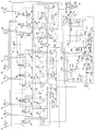
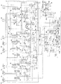
- FIG. 1 shows the hydraulic drive apparatus of the hydraulic shovel (construction machine) concerning the 1st Embodiment of this invention. It is a figure which shows the opening area characteristic of each meter-in channel
- FIG. 1 is a diagram showing a hydraulic drive device for a hydraulic excavator (construction machine) according to a first embodiment of the present invention.
- a hydraulic drive device is driven by a prime mover (for example, a diesel engine) 1 and a prime mover 1, and discharges pressure oil to first and second pressure oil supply paths 105 and 205.
- a split flow type variable displacement main pump 102 first hydraulic pump having the second discharge ports 102a and 102b, and a third discharge driven by the prime mover 1 to discharge the pressure oil to the third pressure oil supply passage 305. It is discharged from a single flow type variable displacement main pump 202 (second hydraulic pump) having a port 202 a, first and second discharge ports 102 a and 102 b of the main pump 102, and a third discharge port 202 a of the main pump 202.
- a plurality of actuators 3a, 3b, 3c, 3d, 3e, 3f, 3g, 3h driven by pressure oil; are connected to the third pressure oil supply passages 105, 205, and 305, and are supplied to the plurality of actuators 3 a to 3 h from the first and second discharge ports 102 a and 102 b of the main pump 102 and the third discharge port 202 a of the main pump 202.
- a control valve unit 4 for controlling the flow of pressure oil, a regulator 112 (first pump control device) for controlling the discharge flow rates of the first and second discharge ports 102a and 102b of the main pump 102, and the main pump 202.
- a regulator 212 second pump control device for controlling the discharge flow rate of the third discharge port 202a.
- the control valve unit 4 is connected to the first to third pressure oil supply paths 105, 205, and 305, and a plurality of control valve units 4 are provided from the first and second discharge ports 102 a and 102 b of the main pump 102 and the third discharge port 202 a of the main pump 202.
- a plurality of flow control valves 6a, 6b, 6c, 6d, 6e, 6f, 6g, 6h, 6i, and 6j for controlling the flow rate of the pressure oil supplied to the actuators 3a to 3h, and a plurality of flow control valves 6a to 6j.
- a plurality of pressure compensation valves 7a, 7b, 7c, 7d, 7e, 7f, 7g, 7h, 7i for controlling the differential pressure across the plurality of flow control valves 6a to 6j, respectively, so that the differential pressure before and after becomes equal to the target differential pressure.
- the main relief valve 314 that controls the pressure not to exceed the set pressure and the first pressure oil supply path 105 are connected to the first pressure oil supply path 105 by the pressure oil discharged from the first discharge port 102a.
- the pressure is opened and the pressure oil in the first pressure oil supply passage 105 is turned on. Is connected to the unload valve 115 and the second pressure oil supply path 205, and the pressure of the second pressure oil supply path 205 becomes the maximum load pressure of the actuator driven by the pressure oil discharged from the second discharge port 102 b.
- the set pressure (predetermined pressure) of the spring is added to the maximum load pressure of the actuator that is connected to the pressure oil supply path 305 and the pressure of the third pressure oil supply path 305 is driven by the pressure oil discharged from the third discharge port 202a.
- an unload valve 315 that opens when the pressure (unload valve set pressure) becomes higher, and returns the pressure oil in the third pressure oil supply passage 305 to the tank.
- the control valve unit 4 is also connected to the load ports of the flow control valves 6d, 6f, 6i, 6j connected to the first pressure oil supply passage 105, and the maximum load pressure Plmax1 of the actuators 3a, 3b, 3d, 3f is set.
- the first load pressure detection circuit 131 including the shuttle valves 9d, 9f, 9i, 9j to be detected and the load ports of the flow control valves 6b, 6c, 6g connected to the second pressure oil supply path 205 are connected to the actuator 3b.
- a third load pressure detection circuit 133 connected to the load port and including shuttle valves 9e and 9h for detecting a load pressure (maximum load pressure) Plmax3 of the actuators 3a, 3e and 3h;
- the pressure of the passage 105 that is, the pressure of the first discharge port 102a) P1 and the maximum load pressure Plmax1 detected by the first load pressure detection circuit 131 (actuators 3a, 3b, 3d connected to the first pressure oil supply passage 105)
- 3f (maximum load pressure of 3f) (LS differential pressure) is output as the absolute pressure Pls1, the differential pressure reducing valve 111, the pressure of the second pressure oil supply passage 205 (that is, the pressure of the second discharge port 102b) P2 and the second pressure
- the difference (LS differential pressure) from the maximum load pressure Plmax2 (the maximum load pressure of the actuators 3b, 3c, 3g connected to the second pressure oil supply passage 205) detected by the two-load pressure detection circuit 132 is defined as the absolute pressure Pls2.
- the differential pressure reducing valve 211 to be output, the pressure of the third pressure oil supply passage 305 (that is, the discharge pressure of the main pump 202 or the pressure of the third discharge port 202a) P3 and the maximum load pressure detection circuit 133 are detected.
- a differential pressure reducing valve 311 that outputs a difference (LS differential pressure) as an absolute pressure Pls3 from the load pressure Plmax3 (load pressure of the actuators 3a, 3e, 3h connected to the third pressure oil supply passage 305) is provided.
- the absolute pressures Pls1, Pls2, and Pls3 output by the differential pressure reducing valves 111, 211, and 311 are appropriately referred to as LS differential pressures Pls1, Pls2, and Pls3.
- the above-described unload valve 115 receives the maximum load pressure Plmax1 detected by the first load pressure detection circuit 131 as the maximum load pressure of the actuator driven by the pressure oil discharged from the first discharge port 102a.
- the maximum load pressure Plmax2 detected by the second load pressure detection circuit 132 is guided to the unload valve 215 as the maximum load pressure of the actuator driven by the pressure oil discharged from the second discharge port 102b.
- a maximum load pressure Plmax3 detected by the third load pressure detection circuit 133 is guided to the unload valve 315 as the maximum load pressure of the actuator driven by the pressure oil discharged from the third discharge port 202a.
- the LS differential pressure Pls1 output from the differential pressure reducing valve 111 is led to the pressure compensating valves 7d, 7f, 7i, 7j connected to the first pressure oil supply passage 105 and the regulator 112 of the main pump 102, and the differential pressure
- the LS differential pressure Pls2 output from the pressure reducing valve 211 is led to the pressure compensating valves 7b, 7c, 7g connected to the second pressure oil supply path 205 and the regulator 112 of the main pump 102, and the differential pressure reducing valve 311 outputs it.
- the LS differential pressure Pls3 is guided to the pressure compensation valves 7a, 7e, 7h connected to the third pressure oil supply passage 305 and the regulator 212 of the main pump 202.
- the actuator 3a is connected to the first discharge port 102a via the flow control valve 6i and the pressure compensation valve 7i and the first pressure oil supply passage 105, and the flow control valve 6a and the pressure compensation valve 7a and the third pressure. It is connected to the third discharge port 202a via the oil supply path 305.
- the actuator 3a is, for example, a boom cylinder that drives a boom of a hydraulic excavator, the flow control valve 6a is for main drive of the boom cylinder 3a, and the flow control valve 6i is for assisting boom cylinder 3a.
- the actuator 3b is connected to the first discharge port 102a via the flow control valve 6j and the pressure compensation valve 7j and the first pressure oil supply path 105, and the flow control valve 6b, the pressure compensation valve 7b and the second pressure oil supply path. It is connected to the second discharge port 102b via 205.
- the actuator 3b is, for example, an arm cylinder that drives an arm of a hydraulic excavator, the flow control valve 6b is for main drive of the arm cylinder 3b, and the flow control valve 6j is for assist drive of the arm cylinder 3b.
- the actuators 3d and 3f are connected to the first discharge port 102a via the flow rate control valves 6d and 6f and the pressure compensation valves 7d and 7f and the first pressure oil supply path 105, respectively.
- the actuators 3c and 3g are respectively connected to the flow rate control valves 6c and 6f, 6g and the pressure compensation valves 7c and 7g and the second pressure oil supply passage 205 are connected to the second discharge port 102b.
- the actuators 3d and 3f are, for example, a bucket cylinder that drives a bucket of a hydraulic excavator and a left traveling motor that drives the left crawler track of the lower traveling body.
- the actuators 3c and 3g are, for example, a turning motor that drives an upper turning body of a hydraulic excavator and a right traveling motor that drives a right crawler track of the lower traveling body.
- the actuators 3e and 3h are connected to the third discharge port 102a via the flow control valves 6e and 6h, the pressure compensation valves 7e and 7h, and the third pressure oil supply passage 305, respectively.
- the actuators 3e and 3h are, for example, a swing cylinder that drives a swing post of a hydraulic excavator and a blade cylinder that drives a blade.
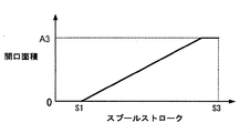
- FIG. 2A shows the meter-in of each of the flow control valves 6c to 6h of the actuators 3c to 3h other than the actuator 3a which is a boom cylinder (hereinafter referred to as boom cylinder 3a as appropriate) and the actuator 3b which is an arm cylinder (hereinafter referred to as arm cylinder 3b as appropriate).
- the opening area increases as the spool stroke increases beyond the dead zone 0-S1, and the opening area characteristic is set so that the opening area becomes the maximum opening area A3 immediately before the maximum spool stroke S3. Yes.
- the maximum opening area A3 has a specific size depending on the type of actuator.
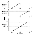
- 2B is a diagram showing the opening area characteristics of the meter-in passages of the flow control valves 6a and 6i of the boom cylinder 3a and the flow control valves 6b and 6j of the arm cylinder 3b.
- the flow control valve 6a for the main drive of the boom cylinder 3a increases in opening area as the spool stroke increases beyond the dead zone 0-S1, reaches the maximum opening area A1 in the intermediate stroke S2, and then reaches the maximum spool stroke.
- the opening area characteristic is set so that the maximum opening area A1 is maintained until S3. The same applies to the opening area characteristics of the main drive flow control valve 6b of the arm cylinder 3b.
- the flow control valve 6i for assist driving of the boom cylinder 3a has an opening area of zero until the spool stroke reaches the intermediate stroke S2, and the opening area increases as the spool stroke increases beyond the intermediate stroke S2.
- the opening area characteristic is set so that the maximum opening area A2 is obtained immediately before the maximum spool stroke S3.
- the opening area characteristics of the flow control valve 6j for assist driving of the arm cylinder 3b are also the same.
- FIG. 2B is a diagram showing a composite opening area characteristic of meter-in passages of the flow control valves 6a and 6i of the boom cylinder 3a and the flow control valves 6b and 6j of the arm cylinder 3b.
- the meter-in passages of the flow control valves 6a and 6i of the boom cylinder 3a each have the above opening area characteristics.
- the opening area increases as the spool stroke increases beyond the dead zone 0-S1, and the maximum
- the combined opening area characteristic is the maximum opening area A1 + A2 immediately before the spool stroke S3.
- the synthetic opening area characteristics of the flow control valves 6b and 6j of the arm cylinder 3b are the same.
- the combined maximum opening area A1 + A2 of 6b and 6j has a relationship of A1 + A2> A3. That is, the boom cylinder 3a and the arm cylinder 3b are actuators having a maximum required flow rate higher than those of other actuators.
- control valve 4 has an upstream side connected to a pilot pressure oil supply passage 31b (described later) via a throttle 43, and a downstream side connected to operation detection valves 8a, 8b, 8c, 8d, 8f, 8g, 8i, and 8j. And the first switching valve 40, the second switching valve 146 and the third switching valve which are switched based on the operation detection pressure generated by the traveling composite operation detection oil path 53. And a switching valve 246.
- the travel composite operation detection oil path 53 includes an actuator 3f that is a left travel motor (hereinafter referred to as a left travel motor 3f as appropriate) and / or an actuator 3g that is a right travel motor (hereinafter referred to as a right travel motor 3g as appropriate), and a first pressure oil.
- an actuator 3f that is a left travel motor (hereinafter referred to as a left travel motor 3f as appropriate) and / or an actuator 3g that is a right travel motor (hereinafter referred to as a right travel motor 3g as appropriate), and a first pressure oil.
- the operation detection valves 8f, 8g Any one of the operation detection valves 8a, 8b, 8c, 8d, 8i, and 8j is stroked together with the corresponding flow control valve to cut off the communication with the tank. It is, generates an operation detection pressure (operation detection signal) to the oil passage 53.
- the first switching valve 40 When the first switching valve 40 is not a travel combined operation, the first switching valve 40 is in a first position (blocking position) on the lower side in the figure, and blocks communication between the first pressure oil supply path 105 and the second pressure oil supply path 205. During the traveling combined operation, the first pressure oil supply path 105 and the second pressure oil supply path 205 are switched to the second position (communication position) on the upper side in the figure by the operation detection pressure generated in the traveling combined operation detection oil path 53. To communicate.
- the second switching valve 146 is in the first position on the lower side of the figure when it is not a travel combined operation, and guides the tank pressure to the shuttle valve 9g at the most downstream side of the second load pressure detection circuit 132, and during the travel combined operation,
- the operation detection pressure generated in the travel combined operation detection oil passage 53 is switched to the second position on the upper side in the figure, and the maximum load pressure Plmax1 (in the first pressure oil supply passage 105 detected by the first load pressure detection circuit 131) is switched.
- the maximum load pressure of the actuators 3 a, 3 b, 3 d, 3 f to be connected is led to the most downstream shuttle valve 9 g of the second load pressure detection circuit 132.
- the third switching valve 246 is in the first position on the lower side of the drawing when it is not a travel combined operation, and guides the tank pressure to the shuttle valve 9f at the most downstream side of the first load pressure detection circuit 131.
- the operation detection pressure generated in the traveling combined operation detection oil passage 53 is switched to the second position on the upper side in the figure, and the maximum load pressure Plmax2 (in the second pressure oil supply passage 205 is detected by the second load pressure detection circuit 132).
- the maximum load pressure of the actuators 3b, 3c, 3g to be connected is guided to the shuttle valve 9f on the most downstream side of the first load pressure detection circuit 131.
- the left traveling motor 3f and the right traveling motor 3g are actuators that are driven at the same time and perform predetermined functions when the supply flow rate becomes equal at that time.
- the left traveling motor 3f is driven by pressure oil discharged from the first discharge port 102a of the split flow type main pump 102
- the right traveling motor 3g is driven by the second discharge of the split flow type main pump 102. It is driven by pressure oil discharged from the port 102b.
- the hydraulic drive apparatus is connected to a fixed displacement pilot pump 30 driven by the prime mover 1 and a pressure oil supply passage 31 a of the pilot pump 30, and a discharge flow rate of the pilot pump 30.
- a pilot pressure oil supply passage 31b on the downstream side of the prime mover rotation speed detection valve 13, and a constant pilot primary pressure Ppilot is generated in the pilot pressure oil supply passage 31b.
- the pilot relief valve 32 is connected to the pilot pressure oil supply path 31b, and the gate lock lever 24 switches the downstream pilot pressure oil supply path 31c between the pilot pressure oil supply path 31b and the tank.
- Lock valve 100 and pilot pressure oil supply passage 31c downstream of gate lock valve 100 A plurality of operating devices having a plurality of pilot valves (pressure reducing valves) that are connected and generate operating pilot pressures for controlling a plurality of flow rate control valves 6a, 6b, 6c, 6d, 6e, 6f, 6g, and 6h described later. 122, 123, 124a, 124b (FIG. 7).
- the prime mover rotational speed detection valve 13 has a flow rate detection valve 50 connected between the pressure oil supply passage 31a and the pilot pressure oil supply passage 31b of the pilot pump 30, and an absolute pressure Pgr. And a differential pressure reducing valve 51 that outputs as follows.
- the flow rate detection valve 50 has a variable restrictor 50a that increases the opening area as the passing flow rate (discharge flow rate of the pilot pump 30) increases.
- the oil discharged from the pilot pump 30 passes through the variable throttle 50a of the flow rate detection valve 50 and flows toward the pilot oil passage 31b.
- a differential pressure increases and decreases in the variable throttle portion 50a of the flow rate detection valve 50 as the passing flow rate increases, and the differential pressure reducing valve 51 outputs the differential pressure before and after as an absolute pressure Pgr. Since the discharge flow rate of the pilot pump 30 changes depending on the rotation speed of the prime mover 1, the discharge flow rate of the pilot pump 30 can be detected by detecting the differential pressure across the variable throttle 50a. Can be detected.
- the absolute pressure Pgr output from the prime mover rotation speed detection valve 13 (differential pressure reducing valve 51) is guided to the regulators 112 and 212 as the target LS differential pressure.
- the absolute pressure Pgr output from the differential pressure reducing valve 51 is appropriately referred to as an output pressure Pgr or a target LS differential pressure Pgr.
- the regulator 112 (first pump control device) includes a low pressure selection valve 112a for selecting a low pressure side of the LS differential pressure Pls1 output from the differential pressure reduction valve 111 and the LS differential pressure Pls2 output from the differential pressure reduction valve 211, and a low pressure selection Load sensing drive so that the LS differential pressure Pls12 and the output pressure Pgr of the motor speed detection valve 13, which is the target LS differential pressure, are led and become lower as the LS differential pressure Pls12 becomes smaller than the target LS differential pressure Pgr.
- the LS control valve 112b for changing the pressure (hereinafter referred to as LS drive pressure Px12) and the LS drive pressure Px12 are guided, and the tilt angle (capacity) of the main pump 102 is increased as the LS drive pressure Px12 becomes lower, and the discharge flow rate.
- the pressures of the LS control piston 112c that controls the tilt angle of the main pump 102 and the first and second discharge ports 102a and 102b of the main pump 102 are led so that the Torque control (horsepower control) pistons 112e and 112d (first torque control actuators) that control the tilt angle of the main pump 102 so as to reduce the tilt angle of the swash plate of the main pump 102 and reduce the absorption torque when the force increases ) And a spring 112u which is a biasing means for setting a maximum torque T12max (see FIG. 3A).
- the low pressure selection valve 112a, the LS control valve 112b, and the LS control piston 112c are pressures at which the discharge pressure of the main pump 102 (the discharge pressure on the high pressure side of the first and second discharge ports 102a and 102b) is discharged from the main pump 102.
- the capacity of the main pump 102 is controlled so as to be higher by the target differential pressure (target LS differential pressure Pgr) than the maximum load pressure of the actuator driven by oil (high pressure side pressure of the maximum load pressure Plmax1 and the maximum load pressure Plmax2).
- target differential pressure target LS differential pressure Pgr
- the maximum load pressure of the actuator driven by oil high pressure side pressure of the maximum load pressure Plmax1 and the maximum load pressure Plmax2
- the torque control pistons 112d and 112e and the spring 112u increase at least one of the discharge pressure of each of the first and second discharge ports 102a and 102b of the main pump 102 (discharge pressure of the main pump 102) and the capacity of the main pump 102.
- a first torque control unit is configured to control the capacity of the main pump 102 so that the absorption torque of the main pump 102 does not exceed the maximum torque T12max set by the spring 112u. .
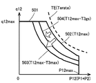
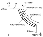
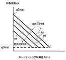
- 3A and 3C are diagrams showing the torque control characteristics obtained by the first torque control unit (torque control pistons 112d and 112e and the spring 112u) and the effect of the present embodiment.
- P12 is a total P1 + P2 of the pressures P1 and P2 of the first and second discharge ports 102a and 102b of the main pump 102 (discharge pressure of the main pump 102), and q12 is an inclination of the main pump 102.
- the tilt angle (capacity) of the plate, P12max is the sum of the maximum discharge pressures of the first and second discharge ports 102a, 102b of the main pump 102 obtained by the set pressure of the main relief valves 114, 214, and q12max is This is the maximum tilt angle determined by the structure of the main pump 102.
- the absorption torque of the main pump 102 can be expressed by the product of the discharge pressure P12 (P1 + P2) of the main pump 102 and the tilt angle q12.
- the maximum absorption torque of the main pump 102 is set to T12max (maximum torque) indicated by the curve 502 by the spring 112u.
- T12max maximum torque
- the main pump 102 tilts so that the absorption torque of the main pump 102 does not increase any more.
- the angle is limited by the torque control pistons 112d and 112e of the regulator 112. For example, when the discharge pressure of the main pump 102 increases while the tilt angle of the main pump 102 is on any one of the curves 502, the torque control pistons 112d and 112e set the tilt angle q12 of the main pump 102 along the curve 502.
- the torque control pistons 112d and 112e have the tilt angle q12 of the main pump 102 increased.
- the tilt angle on the curve 502 is limited to be held.
- symbol TE is a curve indicating the rated output torque Terate of the prime mover 1
- the maximum torque T12max is set to a value smaller than Terate.
- the first load sensing control unit (the low pressure selection valve 112a, the LS control valve 112b, and the LS control piston 112c) has the absorption torque of the main pump 102 smaller than the maximum torque T12max, and is subject to the torque control limitation by the first torque control unit. It functions when not in operation, and controls the capacity of the main pump 102 by load sensing control.
- the regulator 212 (second pump control device) receives the LS differential pressure Pls3 output from the differential pressure reducing valve 311 and the output pressure Pgr of the motor speed detection valve 13 that is the target LS differential pressure, and the LS differential pressure Pls3 is obtained.
- the LS control valve 212b for changing the load sensing driving pressure (hereinafter referred to as LS driving pressure Px3) and the LS driving pressure Px3 are led so that the LS driving pressure Px3 becomes lower as the pressure becomes lower than the target LS differential pressure Pgr.
- the LS control piston 212c load sensing control actuator for controlling the tilt angle of the main pump 202 so that the tilt angle (capacity) of the main pump 202 is increased and the discharge flow rate is increased, and the discharge pressure of the main pump 202 is
- a torque control (horsepower control) piston 212d second torque control actuator
- a spring 212e as an urging means for setting a maximum torque T3max (see FIG. 3B) are provided.
- the discharge pressure of the main pump 202 is only the target differential pressure (target LS differential pressure Pgr) from the maximum load pressure Plmax3 of the actuator driven by the pressure oil discharged from the main pump 202.
- a second load sensing control unit is configured to control the capacity of the main pump 202 so as to increase.
- the torque control piston 212d and the spring 212e prevent the absorption torque of the main pump 202 from exceeding the maximum torque T3max when at least one of the discharge pressure and capacity of the main pump 202 increases and the absorption torque of the main pump 202 increases.
- capacitance of the main pump 202 is comprised.
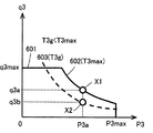
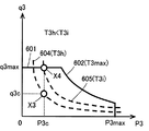
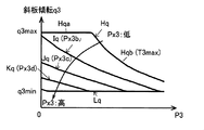
- 3B and 3D are diagrams showing the torque control characteristics obtained by the second torque control unit (the torque control piston 212d and the spring 212e) and the effects of the present embodiment.
- P3 is the discharge pressure of the main pump 202
- q3 is the tilt angle (capacity) of the swash plate of the main pump 202
- P3max is the main pump 202 that is set by the set pressure of the main relief valve 314.
- Q3max is the maximum tilt angle determined by the structure of the main pump 202.
- the absorption torque of the main pump 202 can be represented by the product of the discharge pressure P3 of the main pump 202 and the tilt angle q3.
- the maximum absorption torque of the main pump 202 is set to T3max (maximum torque) indicated by the curve 602 by the spring 212e.
- T3max maximum torque
- the absorption torque of the main pump 202 is increased as in the case of the regulator 112 in FIG. 3A.
- the tilt angle of the main pump 202 is limited by the torque control piston 212d of the regulator 212 so as not to increase further.
- the second load sensing control unit (LS control valve 212b and LS control piston 212c) functions when the absorption torque of the main pump 202 is smaller than the maximum torque T3max and is not subject to torque control restrictions by the second torque control unit.
- the capacity of the main pump 202 is controlled by load sensing control.
- the regulator 112 (first pump control device) is guided by the discharge pressure of the main pump 202 and the LS drive pressure Px3 of the regulator 212, and the main pump 202 (second hydraulic pump) limits the torque control.
- the absorption torque of the main pump 202 is simulated both when operating at the maximum torque T3max of torque control and when the main pump 202 is not limited by torque control and performs capacity control by load sensing control.
- the torque feedback circuit 112v that corrects and outputs the discharge pressure of the main pump 202 based on the discharge pressure of the main pump 202 and the LS drive pressure Px3 of the regulator 212 so as to achieve the above characteristics, and the output pressure of the torque feedback circuit 112v As the output pressure of the torque feedback circuit 112v increases A torque feedback piston 112f (third torque control actuator) that controls the tilt angle of the main pump 102 so that the tilt angle (capacity) of the swash plate of the in-pump 102 is decreased and the maximum torque T12max set by the spring 112u is decreased. ).
- the arrows indicate the effects of the torque feedback circuit 112v and the torque feedback piston 112f.
- the torque feedback circuit 112v corrects the discharge pressure of the main pump 202 so as to have a characteristic simulating the absorption torque of the main pump 202, and the torque feedback piston 112f
- the maximum torque T12max set by the spring 112u is decreased by the output pressure of the torque feedback circuit 112v.
- the torque feedback circuit 112v includes a first fixed throttle 112i to which the discharge pressure of the main pump 202 is guided, a variable throttle valve 112h that is located on the downstream side of the first fixed throttle 112i, and the downstream side is connected to the tank.
- the first pressure dividing circuit 112r that outputs the pressure of the oil passage 112m between the fixed throttle 112i and the variable throttle valve 112h, and the output pressure of the first pressure dividing circuit 112r (pressure of the oil passage 112m) are led,
- the output pressure of the first voltage divider circuit 112r is output as it is, and when the output pressure of the first voltage divider circuit 112r is higher than the set pressure, the first voltage divider circuit
- the variable pressure reducing valve 112g for reducing the output pressure of 112r to the set pressure and outputting it, the second fixed throttle 112k to which the discharge pressure of the main pump 202 is guided, and the downstream side of the second fixed throttle 112k
- a second voltage dividing circuit 112s having a third fixed throttle 112l connected to the tank on the downstream side and outputting the pressure of the oil passage 112n between the second fixed throttle 112k and the third fixed throttle 112l;
- a shuttle valve high pressure selection
- variable throttle valve 112h of the first voltage dividing circuit 112r is fully closed when the LS drive pressure Px3 of the regulator 212 is guided to the side where the opening is in the opening direction, and this LS drive pressure Px3 is the tank pressure, and the LS drive As the pressure Px3 increases, the opening area increases (the pressure in the oil passage 112m between the first fixed throttle 112i and the variable throttle valve 112h decreases), and the LS drive pressure Px3 is piloted in the pilot pressure oil supply passage 31b. When the pilot primary pressure Ppilot generated by the relief valve 32 is reached, the position is switched to the right side in FIG. 1 so as to have a predetermined maximum opening area.
- the variable pressure reducing valve 112g receives the LS driving pressure Px3 of the regulator 212, and when the LS driving pressure Px3 is a tank pressure, the set pressure becomes a predetermined maximum value (initial value), and the LS driving pressure Px3 is high. As the set pressure is lowered, the set pressure becomes a predetermined minimum value when the LS drive pressure Px3 increases to a constant pilot primary pressure Ppilot in the pilot pressure oil supply passage 31b.
- the opening areas of the first fixed throttle 112i and the second fixed throttle 112k are the same, and the maximum opening when the opening area of the third fixed throttle 112l and the variable throttle valve 112h are switched to the right position in FIG.
- the area is the same (the throttle characteristic of the third fixed throttle 112l is the same as the throttle characteristic of the variable throttle valve 112h (pressure regulating valve) when the LS driving pressure Px3 with the main pump 202 as the minimum tilt angle is introduced. Is configured).
- the output characteristic of the second voltage dividing circuit 112s is set to be the same as the output characteristic of the first voltage dividing circuit 112r when the LS driving pressure Px3 having the main pump 202 as the minimum tilt angle is introduced. Has been.
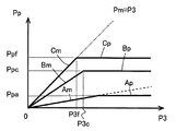
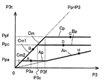
- FIG. 4A is a diagram illustrating output characteristics of a circuit portion including the first voltage dividing circuit 112r and the variable pressure reducing valve 112g of the torque feedback circuit 112v
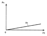
- FIG. 4B is a diagram illustrating the second voltage dividing circuit 112s of the torque feedback circuit 112v.
- FIG. 4C is a diagram illustrating output characteristics of the torque feedback circuit 112v as a whole.
- first voltage dividing circuit 112r and variable pressure reducing valve 112g >>
- P3 is the discharge pressure of the main pump 202 as described above
- Pp is the output pressure of the variable pressure reducing valve 112g (pressure in the oil passage 112p downstream of the variable pressure reducing valve 112g)
- Pm is the first minute. This is the output pressure of the pressure circuit 112r (pressure in the oil passage 112m between the first fixed throttle 112i and the variable throttle valve 112h).
- a required flow rate (hereinafter simply referred to as a required flow rate of the flow control valve) set in the main pump 202 is set by the flow control valve opening area.
- a required flow rate of the flow control valve set in the main pump 202 is set by the flow control valve opening area.
- T3 maximum torque
- a so-called saturation state occurs where the discharge flow rate of the main pump 202 is insufficient with respect to the required flow rate.
- Pls3 ⁇ Pgr the LS control valve 212b is switched to the right position in FIG. 1, and the LS drive pressure Px3 becomes equal to the tank pressure (the boom raising full operation (c) described later).
- the opening area of the variable throttle valve 112h is minimum (fully closed), and the output pressure (pressure in the oil passage 112m) Pm of the first voltage dividing circuit 112r is the discharge pressure of the main pump 202. Same as P3.
- the set pressure of the variable pressure reducing valve 112g is the initial value Ppf. For this reason, when the discharge pressure P3 of the main pump 202 rises, the output pressure Pp of the variable pressure reducing valve 112g changes like the straight lines Cm and Cp.
- the output pressure Pp does not increase any more and is limited to Ppf as in the straight line Cp.
- the LS control valve 212b strokes from the left position in FIG. 1 so that Pls3 becomes equal to Pgr.
- the LS drive pressure Px3 rises to the intermediate pressure between the constant pilot primary pressure Ppilot generated by the pilot relief valve 32 and the tank pressure (the boom raising fine operation (b) described later and the water averaging operation (f )).
- the opening area of the variable throttle valve 112h is an intermediate value between fully closed and fully open (maximum), and the output pressure of the first voltage dividing circuit 112r Pm decreases to a value obtained by dividing the discharge pressure P3 of the main pump 202 by the ratio of the opening area of the first fixed throttle 112i and the variable throttle valve 112h.
- the set pressure Pp of the variable pressure reducing valve 112g decreases from the initial value Ppf to Ppc. For this reason, when the discharge pressure P3 of the main pump 202 rises, the output pressure Pp of the variable pressure reducing valve 112g changes like the straight lines Bm and Bp. At this time, the slope of the straight line Bm (change rate of the output pressure Pm) is smaller than the straight line Cm, and the pressure Ppc of the straight line Bp is lower than the pressure Ppf of the straight line Cp.
- the opening area of the variable throttle valve 112h becomes the maximum, and the output pressure Pm of the first voltage dividing circuit 112r becomes the lowest.
- the set pressure of the variable pressure reducing valve 112g is the minimum Ppa. For this reason, when the discharge pressure P3 of the main pump 202 increases, the output pressure of the variable pressure reducing valve 112g changes like the straight lines Am and Ap. At this time, the slope of the straight line Am (change rate of the output pressure Pm) is the smallest, and the pressure Ppa of the straight line Ap is the lowest pressure.
- Pn is the output pressure of the second voltage dividing circuit 112s (pressure in the oil passage 112n between the second fixed throttle 112k and the third fixed throttle 112l).
- the output pressure Pn of the second voltage dividing circuit 112s is a pressure obtained by dividing the discharge pressure P3 of the main pump 202 by the ratio of the opening areas of the second fixed throttle 112k and the third fixed throttle 112l, and this pressure is the main pump.
- the discharge pressure P3 of 202 is increased, the discharge pressure P3 increases in a linear proportion as a straight line An.
- the opening area of the second fixed throttle 112k of the second voltage dividing circuit 112s is the same as that of the first fixed throttle 112i of the first voltage dividing circuit 112r, and the opening area of the third fixed throttle 112l of the second voltage dividing circuit 112s is
- the LS drive pressure Px3 is the pilot primary pressure Ppilot, which is the same as the maximum opening area of the variable throttle valve 112h when switched to the right position in FIG. Therefore, the straight line An is a straight line having the same inclination as the straight line Am in FIG. 4A.
- P3t is the output pressure of the torque feedback circuit 112v.
- the high pressure side of the output pressure of the variable pressure reducing valve 112g and the output pressure of the second voltage dividing circuit 112s is selected and output as the output pressure of the torque feedback circuit 112v by the shuttle valve 112j. Therefore, the change in the output pressure P3t of the torque feedback circuit 112v when the discharge pressure P3 of the main pump 202 increases is as shown in FIG. 4C. That is, when the LS drive pressure Px3 is a tank pressure and when the pressure increases to an intermediate pressure of the pilot primary pressure Ppilot with respect to the tank pressure, the straight lines Cm and Cp and the variable pressure reducing valves 112g of the straight lines Bm and Bp in FIG.
- the output pressure Pp is selected, and the torque feedback circuit 112v sets the straight lines Cm and Cp and the straight lines Bm and Bp, respectively, and sets the straight line An.
- the LS drive pressure Px3 rises to the pilot primary pressure Ppilot, the output pressure Pn of the second voltage dividing circuit 112s of the straight line An in FIG. 4B is selected, and the torque feedback circuit 112v is set to the straight line An.
- the torque feedback circuit 112v corrects and outputs the discharge pressure of the main pump 202 so as to have a characteristic simulating the absorption torque of the main pump 202.
- the position of the capacity changing member (swash plate) of the main pump 202 is determined by the LS control piston 212c on which the LS driving pressure acts and the main pump.
- Each of the torque control pistons 212d to which the discharge pressure 202 is applied is determined by a balance between the resultant force of pushing the swash plate and the force of the spring 212e, which is a biasing means for setting the maximum torque, pushing the swash plate in the opposite direction. For this reason, the tilt angle of the main pump 202 at the time of load sensing control is not only changed by the LS driving pressure, but is also affected by the discharge pressure of the main pump 202.
- FIG. 5 is a diagram showing the relationship among the LS drive pressure Px3 of the regulator 212, the discharge pressure P3 of the main pump 202, and the tilt angle q3 of the main pump 202.
- the tilt angle q3 of the main pump 202 is the minimum q3min, and the LS drive pressure Px3 decreases. Accordingly, the tilt angle q3 of the main pump 202 increases as shown by, for example, the straight line R1, and when the LS drive pressure Px3 decreases to the tank pressure, the tilt angle q3 of the main pump 202 becomes the maximum q3max.
- the tilt angle q3 of the main pump 202 decreases as straight lines R2, R3, and R4.
- FIG. 6A is a diagram showing the relationship between torque control and load sensing control in the regulator 212 of the main pump 202 (the relationship between the discharge pressure, the tilt angle, and the LS drive pressure Px3 of the main pump 202), and FIG. 6A is a diagram illustrating a relationship between torque control and load sensing control (relationship between discharge pressure, absorption torque, and LS drive pressure Px3 of the main pump 202) by replacing the vertical axis of 6A with the absorption torque of the main pump 202.
- a straight line Hqa of the characteristic Hq corresponds to the straight line 601 in FIG. 3B and is a characteristic of the maximum tilt angle q3max determined by the structure of the main pump 202.
- a curve Hqb of the characteristic Hq corresponds to the curve 602 in FIG. 3B and is a characteristic of the maximum torque T3max set by the spring 212e.
- the tilt angle q3 is constant at q3max as shown by the straight line Hqa (FIG. 6A).
- the absorption torque T3 of the main pump 202 increases substantially linearly as the discharge pressure P3 increases as shown by the straight line Hta (FIG. 6B).
- the tilt angle q3 of the main pump 202 is equal to the discharge pressure P3 as shown by the curve Iq as described above. Since the pressure decreases due to the increase, the tilt angle is smaller than the tilt angle on the curve Hqb of T3max on the high pressure side of the discharge pressure P3 (FIG. 6A).
- the absorption torque T3 of the main pump 202 increases with a gentler slope (change rate) than the curve HTa as the curve ITa increases as the discharge pressure P3 increases, and eventually exceeds the T3max as shown by the curve ITb.
- a small maximum torque T3b is reached and becomes substantially constant (FIG. 6B).
- the tilt angle q3 is not less than the minimum tilt angle q3min determined by the structure of the main pump 202, and the absorption torque T3 is not less than the minimum torque T3min of the straight line LT corresponding to the minimum tilt angle q3min.
- the absorption torque T3 of the main pump 202 increases with a gentler slope (change rate ITa>JTa> KTa) than the curve ITa as the discharge pressure P3 increases, as indicated by the curves JTa, KTa,
- the maximum torques T3c and T3d (T3b>T3c> T3d) smaller than T3b are reached and become almost constant (FIG. 6B).
- the tilt angle q3 is not less than the minimum tilt angle q3min determined by the structure of the main pump 202, and the absorption torque T3 is less than the minimum torque T3min of the straight line LT corresponding to the minimum tilt angle q3min.
- the minimum torque T3min changes as a straight line LT in FIG. 6B. That is, the minimum torque T3min increases with the smallest inclination as the straight line LT increases as the discharge pressure P3 increases.
- the increase rate of the output pressure P3t of the torque feedback circuit 112v when the discharge pressure P3 of the main pump 202 increases is increased as the LS drive pressure Px3 becomes higher, as shown by the straight lines Cm and Bm of FIG. 4C.
- the maximum value of the output pressure P3t of the torque feedback circuit 112v decreases as the LS drive pressure Px3 increases, as indicated by the straight lines Cp and Bp in FIG. 4C.
- the output pressure P3t of the torque feedback circuit 112v when the discharge pressure P3 of the main pump 202 rises when the main pump 202 is at the minimum tilt angle q3min increases with the smallest inclination (increase rate) like the straight line An. To do.
- the increase rate of the output pressure P3t of the straight lines Cm, Bm is the increase of the absorption torque of the curves HTa, ITa, JTa, KTa, LT shown in FIG.
- the LS driving pressure Px3 changes so as to decrease
- the maximum value Ppf of the output pressure P3t of the straight lines Cp, Bp shown in FIG. 4C is the curves HTb, ITb, JTb shown in FIG. 6B.
- the maximum absorption torque of KTb it changes so as to decrease as the LS drive pressure Px3 increases.
- the torque feedback circuit 112v is loaded when the main pump 202 is not limited by torque control.
- the discharge pressure of the main pump 202 is corrected so as to have a characteristic simulating the absorption torque of the main pump 202 and output.
- FIG. 7 is a view showing an appearance of a hydraulic excavator on which the above-described hydraulic drive device is mounted.
- a hydraulic excavator well known as a work machine includes a lower traveling body 101, an upper swing body 109, and a swing-type front work machine 104.
- the front work machine 104 includes a boom 104a, an arm 104b, The bucket 104c is configured.
- the upper turning body 109 can turn with respect to the lower traveling body 101 by a turning motor 3c.
- a swing post 103 is attached to a front portion of the upper swing body 109, and a front work machine 104 is attached to the swing post 103 so as to be movable up and down.
- the swing post 103 can be rotated in the horizontal direction with respect to the upper swing body 109 by expansion and contraction of the swing cylinder 3e.
- the boom 104a, the arm 104b, and the bucket 104c of the front work machine 104 are the boom cylinder 3a, the arm cylinder 3b, and the bucket cylinder. It can be turned up and down by 3d expansion and contraction.
- a blade 106 that moves up and down by expansion and contraction of the blade cylinder 3h is attached to the central frame of the lower traveling body 102.
- the lower traveling body 101 travels by driving the left and right crawler belts 101a and 101b by the rotation of the traveling motors 3f and 3g.
- the upper swing body 109 is provided with a canopy type driver's cab 108.
- the driver's cab 108 there is a driver's seat 121, left / right operation devices 122 and 123 for front / turn (only the left side is shown in FIG. 7), and for driving.
- Operating devices 124a and 124b (only the left side is shown in FIG. 7), a swing operating device and a blade operating device (not shown), a gate lock lever 24, and the like.
- the operation levers of the operation devices 122 and 123 can be operated in any direction based on the cross direction from the neutral position. When the left operation lever of the operation device 122 is operated in the front-rear direction, the operation device 122 is used for turning.
- the operating device 122 When functioning as an operating device and operating the operating lever of the operating device 122 in the left-right direction, the operating device 122 functions as an operating device for the arm, and when operating the operating lever of the right operating device 123 in the front-rear direction, The operation device 123 functions as a boom operation device. When the operation lever of the operation device 123 is operated in the left-right direction, the operation device 123 functions as a bucket operation device.
- a prime mover rotational speed detection valve 13 is connected to the pressure oil supply passage 31a.
- the prime mover rotational speed detection valve 13 is configured by a flow rate detection valve 50 and a differential pressure reducing valve 51 according to the discharge flow rate of the pilot pump 30. Is output as absolute pressure Pgr (target LS differential pressure).
- a pilot relief valve 32 is connected downstream of the prime mover rotation speed detection valve 13 to generate a constant pressure (pilot primary pressure Ppilot) in the pilot pressure oil supply passage 31b.
- the maximum load pressures Plmax1, Plmax2, Plmax3 are guided to the unload valves 115, 215, 315, so that the pressures P1, P2, P3 of the first, second and third discharge ports 102a, 102b, 202a are the maximum load pressures.
- the pressure (unload valve set pressure) obtained by adding the set pressure Pun0 of each spring of the unload valves 115, 215, 315 to Plmax1, Plmax2, Plmax3 is maintained.
- the maximum load pressures Plmax1, Plmax2, and Plmax3 are tank pressures as described above, and the tank pressure is approximately 0 MPa.
- the unload valve set pressure becomes equal to the spring set pressure Pun0, and the pressures P1, P2, P3 of the first, second and third discharge ports 102a, 102b, 202a are kept at Pun0 (minimum discharge pressure P3min). Be drunk.
- Pun0 is set slightly higher than the output pressure Pgr of the prime mover rotational speed detection valve 13 that is the target LS differential pressure (Pun0> Pgr).
- the differential pressure reducing valves 111, 211, 311 are respectively pressures P1, P2, P3 and maximum load pressures Plmax1, Plmax2, Plmax3 (tank pressure) of the first, second and third pressure oil supply passages 105, 205, 305.
- the LS differential pressures Pls1 and Pls2 are led to the low pressure selection valve 112a of the regulator 112, and Pls3 is led to the LS control valve 212b of the regulator 212.
- the low-pressure side of the LS differential pressures Pls1 and Pls2 led to the low-pressure selection valve 112a is selected and led to the LS control valve 112b as the LS differential pressure Pls12.
- Pls12> Pgr so the LS control valve 122b is pushed leftward in FIG. 1 to switch to the right position, and the LS drive pressure Px12 is the pilot relief valve.
- the pilot primary pressure Ppilot generated by 32 is increased to the pilot primary pressure Ppilot, which is led to the LS control piston 112c. Since the pilot primary pressure Ppilot is guided to the LS control piston 112c, the capacity (flow rate) of the main pump 102 is kept to a minimum.
- the LS differential pressure Pls3 is guided to the LS control valve 212b of the regulator 212. Since Pls3> Pgr, the LS control valve 212b is pushed rightward in FIG. 1 to switch to the left position, and the LS drive pressure Px3 rises to the pilot primary pressure Ppilot, which is the LS control piston. It is led to 212c. Since the pilot primary pressure Ppilot is guided to the LS control piston 212c, the capacity (flow rate) of the main pump 202 is kept to a minimum.
- the LS drive pressure Px3 becomes equal to the pilot primary pressure Ppilot, so the torque feedback circuit 112v is set to the straight line An in FIG. 4C.
- the output pressure of the torque feedback circuit 112v is the pressure P3tmin at point A on the straight line An in FIG. 4C. It becomes.
- This pressure P3tmin is guided to the torque feedback piston 112f, and the maximum torque of the main pump 102 is set to T12max in FIG. 3A.
- the flow control valve for main drive increases as the operation amount (operation pilot pressure) of the boom operation lever increases.
- the opening area of the meter-in passage 6a increases from zero to A1.
- the opening area of the meter-in passage of the assist control flow control valve 6i is maintained at zero.
- the assist-control flow control valve 6i does not open the meter-in passage even when the boom raising fine operation is switched upward in FIG. 1, and the load detection port remains connected to the tank.
- the first load pressure detection circuit 131 detects the tank pressure as the maximum load pressure Plmax1. Therefore, the capacity (flow rate) of the main pump 102 is kept to a minimum as in the case where all the operation levers are neutral.
- the differential pressure reducing valve 311 absolutely calculates the differential pressure (LS differential pressure) between the pressure P3 of the third pressure oil supply passage 305 and the maximum load pressure Plmax3.
- the pressure Pls3 is output, and this Pls3 is guided to the LS control valve 212b.
- the LS control valve 212b compares the target LS differential pressure Pgr with the LS differential pressure Pls3.
- the load pressure of the boom cylinder 3a is transmitted to the third pressure oil supply passage 305 and the pressure difference between the two is almost eliminated, so the LS differential pressure Pls3 becomes substantially equal to zero. Therefore, since the relationship of Pls3 ⁇ Pgr is established, the LS control valve 212b switches to the left in FIG. 1 and discharges the pressure oil of the LS control piston 212c to the tank. For this reason, the LS drive pressure Px3 decreases, and the capacity (flow rate) of the main pump 202 increases.
- the main pump 202 performs so-called load sensing control in which a necessary flow rate is discharged in accordance with a required flow rate of the flow rate control valve 6a.
- pressure oil at a flow rate corresponding to the input of the boom operation lever is supplied to the bottom side of the boom cylinder 3a, and the boom cylinder 3a is driven in the extending direction.
- the torque feedback circuit 112v is set, for example, by straight lines Bm and Bp in FIG. 4C.
- the discharge pressure P3 of the main pump 202 rises to the pressure of the straight line Bp in FIG. 4C, and the torque feedback circuit 112v has a limited pressure on the straight line Bp in FIG. 4C.
- the torque feedback piston 112f reduces the maximum torque of the main pump 102 from T12max of the curve 502 in FIG. 3A to a value smaller than T12max by an amount corresponding to the output pressure Ppc of the torque feedback circuit 112v.
- the torque feedback circuit 112v The discharge pressure P3a of the pump 202 is corrected to a value simulating the absorption torque T3g at the point X2 (output pressure Ppc), and the torque feedback piston 112f outputs the maximum torque of the main pump 102, T12max of the curve 502 in FIG. 3A. From the curve 504 to T12max-T3gs (T3gs ⁇ T3g).
- the first torque control unit controls the tilt angle of the main pump 102 so that the absorption torque of the main pump 102 does not exceed T12max ⁇ T3gs.
- the sum of the absorption torque of the engine 1 does not exceed the maximum torque T12max, and the stoppage of the prime mover 1 (engine stall) can be prevented.
- the load pressure of the boom cylinder 3a is detected as the maximum load pressure Plmax3 by the third load pressure detection circuit 133 via the load port of the flow rate control valve 6a, and the main pump 202 is controlled according to the maximum load pressure Plmax3.
- the discharge flow rate is controlled so that Pls3 is equal to Pgr, and pressure oil is supplied from the main pump 202 to the bottom side of the boom cylinder 3a.
- the load pressure on the bottom side of the boom cylinder 3a is detected as the maximum load pressure Plmax1 by the first load pressure detection circuit 131 via the load port of the flow rate control valve 6i, and is supplied to the unload valve 115 and the differential pressure reducing valve 111.
- the set pressure of the unload valve 115 becomes a pressure obtained by adding the spring set pressure Pun0 to the maximum load pressure Plmax1 (load pressure on the bottom side of the boom cylinder 3a).
- the oil passage that rises and discharges the pressure oil in the first pressure oil supply passage 105 to the tank is shut off.
- the differential pressure reducing valve 111 absolutely calculates the differential pressure (LS differential pressure) between the pressure P1 of the first pressure oil supply passage 105 and the maximum load pressure Plmax1. Output as pressure Pls1.
- This Pls1 is led to the low pressure selection valve 112a of the regulator 112, and the low pressure side of Pls1 and Pls2 is selected by the low pressure selection valve 112a.
- the LS differential pressure Pls1 is substantially equal to zero and the relationship of Pls1 ⁇ Pgr is established. Therefore, the LS control valve 112b switches to the right in FIG. 1, and the pressure oil of the LS control piston 112c is supplied to the tank. To release. Therefore, the LS drive pressure Px3 decreases, the capacity (flow rate) of the main pump 102 increases, and the flow rate of the main pump 102 is controlled so that Pls1 is equal to Pgr.
- pressure oil is supplied from the first discharge port 102a of the main pump 102 to the bottom side of the boom cylinder 3a, and the boom cylinder 3a is supplied from the third discharge port 202a of the main pump 202 and the first discharge port 102a of the main pump 102. It is driven in the extension direction by the pressure oil that has joined.
- the pressure oil having the same flow rate as the pressure oil supplied to the first pressure oil supply passage 105 is supplied to the second pressure oil supply passage 205, but the pressure oil is supplied to the unload valve 215 as an excessive flow rate. Is returned to the tank.
- the second load pressure detection circuit 132 detects the tank pressure as the maximum load pressure Plmax2, the set pressure of the unload valve 215 becomes equal to the set pressure Pun0 of the spring, and the second pressure oil supply path 205
- the pressure P2 is kept at the low pressure of Pun0.
- the main pump 202 discharges a flow rate according to the required flow rate of the flow control valve 6a.
- the required flow rate is equal to or higher than the flow rate limited by the maximum torque T3 (FIG. 3B)
- the main pump 202 There may be a so-called saturation state in which the discharge flow rate is insufficient with respect to the required flow rate and the detected LS differential pressure Pls3 does not reach the target LS differential pressure Pgr.
- Pls3 ⁇ Pgr and the LS control valve 212b is switched to the position on the right side of FIG. 1, so that the pressure oil of the LS control piston 212c is discharged to the tank via the LS control valve 212b.
- the LS drive pressure Px3 is equal to the tank pressure.
- the torque feedback circuit 112v is set by the straight line Cm and the straight line Cp in FIG. 4C. Since the load pressure for raising the boom is relatively high as described above, the discharge pressure P3 of the main pump 202 is the straight line Cp in FIG. 4C. As the pressure rises, the torque feedback circuit 112v outputs a limited pressure Ppf on the straight line Cp of FIG. 4C.
- the torque feedback piston 112f reduces the maximum torque of the main pump 102 from T12max of the curve 502 in FIG. 3A to a value smaller than T12max by an amount corresponding to the output pressure Ppf of the torque feedback circuit 112v.
- the main pump 202 operates at the X1 point (P3a, q3a) on the curve 602 of the maximum torque T3max in FIG. 3B, and the G point on the straight line Cp in FIG. 4C corresponds to the X1 point.
- the torque feedback circuit 112v corrects and outputs the discharge pressure P3a of the main pump 202 to a value simulating the absorption torque T3max at the point X1 (output pressure Ppf), and the torque feedback piston 112f outputs the maximum torque of the main pump 102. Is reduced from T12max of the curve 502 in FIG. 3A to T12max ⁇ T3max of the curve 503.
- the first torque control unit controls the tilt angle of the main pump 102 so that the absorption torque of the main pump 102 does not exceed T12max ⁇ T3max, and the total absorption torque of the main pumps 102 and 202 becomes the maximum torque T12max.
- the engine 1 is prevented from stopping (engine stall).
- the flow control valve for main drive increases as the operation amount (operation pilot pressure) of the arm operation lever increases.
- the opening area of the 6b meter-in passage increases from zero to A1.
- the opening area of the meter-in passage of the assist control flow control valve 6j is maintained at zero.
- the load pressure on the bottom side of the arm cylinder 3b is detected as the maximum load pressure Plmax2 by the second load pressure detection circuit 132 via the load port of the flow rate control valve 6b. Then, it is guided to the unload valve 215 and the differential pressure reducing valve 211.
- the maximum load pressure Plmax2 is guided to the unload valve 215, the set pressure of the unload valve 215 becomes the pressure obtained by adding the spring set pressure Pun0 to the maximum load pressure Plmax2 (load pressure on the bottom side of the arm cylinder 3b).
- the oil passage that rises and discharges the pressure oil in the second pressure oil supply passage 205 to the tank is shut off.
- the differential pressure reducing valve 211 absolutely calculates the differential pressure (LS differential pressure) between the pressure P2 of the second pressure oil supply passage 205 and the maximum load pressure Plmax2.
- the pressure Pls2 is output, and this Pls2 is guided to the low pressure selection valve 112a of the regulator 112.
- the low pressure selection valve 112a selects the low pressure side of Pls1 and Pls2.
- the load pressure of the arm cylinder 3b is transmitted to the second pressure oil supply passage 205, and there is almost no difference between the two pressures. Therefore, the LS differential pressure Pls2 is substantially equal to zero.
- the LS control valve 112b compares the output pressures Pgr and Pls2 of the prime mover rotational speed detection valve 13 that are target LS differential pressures.
- the pressure oil having the same flow rate as the pressure oil supplied to the second pressure oil supply passage 205 is supplied to the first pressure oil supply passage 105, and the pressure oil is supplied to the tank via the unload valve 115 as an excessive flow rate.
- the first load pressure detection circuit 131 detects the tank pressure as the maximum load pressure Plmax1, the set pressure of the unload valve 115 becomes equal to the set pressure Pun0 of the spring, and the pressure P1 of the first pressure oil supply path 105 Is kept at the low pressure of Pun0.
- the pressure loss of the unload valve 115 when the surplus flow returns to the tank is reduced, and operation with less energy loss becomes possible.
- the torque feedback circuit 112v is set to the straight line An in FIG.
- the torque is set to T12max in FIG. 3A.
- the load pressure on the bottom side of the arm cylinder 3b is detected as the maximum load pressure Plmax2 by the second load pressure detection circuit 132 via the load port of the flow control valve 6b, and the unload valve 215 Shuts off the oil passage for discharging the pressure oil in the second pressure oil supply passage 205 to the tank. Further, the maximum load pressure Plmax2 is led to the differential pressure reducing valve 211, whereby the LS differential pressure Pls2 is outputted and led to the low pressure selection valve 112a of the regulator 112.
- the unload valve 115 blocks the oil passage for discharging the pressure oil in the first pressure oil supply passage 105 to the tank.
- the load pressure of the arm cylinder 3b is transmitted to the first and second pressure oil supply passages 105 and 205, and the difference between the two pressures is almost eliminated. Therefore, the LS differential pressures Pls1 and Pls2 are Both are approximately equal to zero. Therefore, the low pressure selection valve 112a selects either Pls1 or Pls2 as the low pressure side LS differential pressure Pls12, and Pls12 is guided to the LS control valve 112b. In this case, as described above, both Pls1 and Pls2 are substantially equal to zero and Pls12 ⁇ Pgr. Therefore, the LS control valve 112b switches to the right in FIG.
- the torque feedback circuit 112v is set to the straight line An in FIG.
- the torque is set to T12max in FIG. 3A.
- the first torque control unit controls the tilt angle of the main pump 102 so that the absorption torque of the main pump 102 does not exceed the maximum torque T12max, and the prime mover 1 is stopped when the load on the arm cylinder 3b increases ( Engine stall) can be prevented.
- the water leveling operation is a combination of a boom raising fine operation and a full arm cloud operation.
- the actuator is an operation in which the arm cylinder 3b extends and the boom cylinder 3a extends.
- the opening area of the meter-in passage of the flow control valve 6a for main drive of the boom cylinder 3a is A1 or less, which is used for assist drive.
- the opening area of the meter-in passage of the flow control valve 6i is maintained at zero.
- the load pressure of the boom cylinder 3a is detected as the maximum load pressure Plmax3 by the third load pressure detection circuit 133 via the load port of the flow control valve 6a, and the unload valve 315 tanks the pressure oil in the third pressure oil supply passage 305.
- the maximum load pressure Plmax3 is fed back to the regulator 212 of the main pump 202, the capacity (flow rate) of the main pump 202 increases according to the required flow rate (opening area) of the flow control valve 6a, and the third discharge of the main pump 202 is performed.
- Pressure oil at a flow rate corresponding to the input of the boom operation lever is supplied from the port 202a to the bottom side of the boom cylinder 3a, and the boom cylinder 3a is driven in the extending direction by the pressure oil from the third discharge port 202a.
- the valves 115 and 215 block the oil passages for discharging the pressure oil from the first and second pressure oil supply passages 105 and 205 to the tank, respectively.
- the maximum load pressures Plmax1 and Plmax2 are fed back to the regulator 112 of the main pump 102, and the capacity (flow rate) of the main pump 102 increases according to the required flow rate of the flow control valves 6b and 6j.
- Pressure oil having a flow rate corresponding to the input of the arm operation lever is supplied from the second discharge ports 102a and 102b to the bottom side of the arm cylinder 3b, and the arm cylinder 3b is combined pressure from the first and second discharge ports 102a and 102b. Driven in the direction of extension by oil.
- the load pressure of the arm cylinder 3b is usually low and the load pressure of the boom cylinder 3a is often high.
- the hydraulic pump that drives the boom cylinder 3a is the main pump 202
- the hydraulic pump that drives the arm cylinder 3b is the main pump 102, and the like.
- the torque feedback circuit 112v is set, for example, by the straight lines Bm and Bp in FIG. 4C, and the main pump 202 is set at point X2 (P3a in FIG. 3B). , Q3b), and when the point D on the straight line Bp in FIG. 4C corresponds to the point X2, the torque feedback circuit 112v sets the discharge pressure P3a of the main pump 202 to a value simulating the absorption torque T3g at the point X2.
- the torque feedback piston 112f reduces the maximum torque of the main pump 102 from T12max of the curve 502 in FIG. 3A to T12max ⁇ T3gs of the curve 504 (T3gs ⁇ T3g).
- the first torque control unit controls the tilt angle of the main pump 102 so that the absorption torque of the main pump 102 does not exceed T12max ⁇ T3gs.
- the sum of the absorption torques of the main pumps 102 and 202 does not exceed the maximum torque T12max, and the stoppage of the prime mover 1 (engine stall) can be prevented.
- the lifting work is a work in which a wire is attached to a hook provided in the bucket, the load is lifted by the wire and moved to another place. Even when the boom raising fine operation is performed in this hanging work, the boom cylinder 3a bottom side from the third discharge port 202a of the main pump 202 by the load sensing control of the regulator 212 as described in the above (b) or (f). Is supplied with pressure oil, and the boom cylinder 3a is driven in the extending direction.
- the weight of the suspended work is heavy, and the discharge pressure P3 of the main pump 202 is often high, for example, as point H on the straight line An in FIG. 4C.
- the swing motor 3c may be driven simultaneously with the boom raising fine operation to change the position of the suspended load in the turning direction, or the arm cylinder 3b may be driven to change the position of the suspended load in the front-rear direction.
- pressure oil is also discharged from the main pump 102, and the horsepower of the prime mover 1 is consumed by both the main pump 102 and the main pump 202.
- the output pressure of the torque feedback circuit 112v is the output pressure of the variable pressure reducing valve 112g.
- the torque feedback circuit 112v outputs a pressure Ppa lower than the pressure at point H in FIG. 4C.
- the second voltage dividing circuit 112s since the second voltage dividing circuit 112s is provided, even when the discharge pressure P3 of the main pump 202 becomes high as indicated by the point H on the straight line An in FIG. A pressure Pph corresponding to the point H is output, and the maximum torque of the main pump 102 is controlled to be reduced accordingly. Since the absorption torque of the main pump 202 is accurately fed back to the main pump 102 in this way, the main pump 102 and the main pump 202 can be operated even when the boom raising fine operation and the turning or the combined operation of the arm are performed in the lifting work. The total torque consumption of the engine is not excessive, and engine stall can be prevented.
- (H) Earth Removal Work The earth removal work in which the blade 106 is operated to move the earth and sand while traveling is a combined operation in which the traveling motors 3f and 3g and the blade cylinder 106 are driven simultaneously.
- the capacity (flow rate) of the main pump 202 increases in accordance with the required flow rate (opening area) of the flow control valve 6h, for example, as in the fine operation (b) of raising the boom described above.
- Pressure oil at a flow rate corresponding to the input of the blade operation lever is supplied from the third discharge port 202a of the main pump 202 to the blade cylinder 3h, and the blade cylinder 3h is driven by the pressure oil from the third discharge port 202a.
- the main pump 202 operates at the point X3 (P3c, q3c) in FIG. 3D when the LS drive pressure Px3 is at an intermediate pressure between the pilot primary pressure Ppilot and the tank pressure.
- the feedback circuit 112v is set, for example, by straight lines Bm and Bp in FIG. 4C, and corrects and outputs the discharge pressure (for example, P3c) of the main pump 202 to a value simulating the absorption torque (for example, T3h) of the main pump 202.
- the torque feedback piston 112f reduces the maximum torque of the main pump 102 from the T12max of the curve 502 in FIG. 3C to the absorption torque of the curve 505 (eg, T12max ⁇ T3hs) ( T3hs ⁇ T3h).
- the first torque control unit controls the tilt angle of the main pump 102 so that the absorption torque of the main pump 102 does not exceed T12max ⁇ T3hs, and the total absorption torque of the main pumps 102 and 202 becomes the maximum torque T12max.
- the engine 1 is prevented from stopping (engine stall).
- the main pump 202 (second hydraulic pump) is subjected to torque control restrictions and is in an operating state in which it operates at the maximum torque T3max of torque control. Even when the pump 202 is not limited by torque control and is in an operation state in which capacity control is performed by load sensing control, the discharge pressure P3 of the main pump 202 simulates the absorption torque of the main pump 202 by the torque feedback circuit 112v. The corrected torque is corrected so that the maximum torque T12max is reduced by the torque feedback piston 112f (third torque control actuator) by the corrected discharge pressure P3t.
- the absorption torque of the main pump 202 is accurately detected by a pure hydraulic configuration (torque feedback circuit 112v), and the total torque control is accurately performed by feeding back the absorption torque to the main pump 102 side.
- the rated output torque Terate can be used effectively.
- FIG. 8 is a diagram showing a comparative example for explaining the above-described effects of the present embodiment.
- the torque feedback circuit 112v of the regulator 112 in the first embodiment of the present invention shown in FIG. 1 is replaced with a pressure reducing valve 112w (corresponding to the pressure reducing valve 14 described in Patent Document 2).
- the set pressure of the pressure reducing valve 112w is constant, and this set pressure is set to the same value as the initial value Ppf of the set pressure of the variable pressure reducing valve 112g in FIG.
- the output pressure of the pressure reducing valve 112w changes as the straight lines Cm and Cp in FIG. 4C regardless of the LS drive pressure Px3.
- the main pump 202 operates at the X1 point (P3a, q3a) on the curve 602 of the maximum torque T3max in FIG. 3B and the LS drive pressure Px3 is the tank pressure, for example, as in the full boom raising operation (c).
- the pressure reducing valve 112w corrects and outputs the discharge pressure of the main pump 202 to the pressure Ppf on the straight line Cp in FIG. 4C, similarly to the variable pressure reducing valve 112g of the torque feedback circuit 112v in FIG.
- the piston 112f reduces the maximum torque of the main pump 102 from T12max to T12max ⁇ T3max as shown by a curve 503 in FIG. 3A.
- the same effect as in the present embodiment can be obtained also in the comparative example 1.
- the pressure reducing valve 112w corrects the discharge pressure of the main pump 202 to the pressure Ppf on the straight line Cp in FIG.
- the torque feedback piston 112f has the maximum torque of the main pump 102 as shown by a curve 503 in FIG. 3A from T12max to T12max ⁇ T3max. It will be reduced more than necessary.
- the effect of this embodiment can also be obtained when the main pump 202 operates at point X3 (P3c, q3c) in FIG. 3D and the LS drive pressure Px3 is at an intermediate pressure between the pilot primary pressure Ppilot and the tank pressure. Absent. That is, in the comparative example, in this case, the discharge pressure of the main pump 202 is corrected to, for example, the pressure on the straight line Cm in FIG. 4C and output, as in the case of operating at the point X4 on the straight line 601 having the maximum tilt angle q3max. To do.
- the torque feedback piston 112f changes the maximum torque of the main pump 102 from T12max to T12max-T3is as shown by a curve 506 in FIG. 3C. It will decrease more than necessary (T3is ⁇ T3i).
- the main pump 202 operates at the X2 point (P3a, q3b) in FIG. 3B, and the LS drive pressure Px3 is the pilot primary pressure Ppilot and the tank.
- the torque feedback circuit 112v is set, for example, by the straight lines Bm and Bp in FIG. 4C, and the torque feedback circuit 112v is set to discharge pressure (for example, P3a) of the main pump 202. Is corrected to a value simulating the absorption torque (for example, T3g) of the main pump 202 (for example, the output pressure Ppc at point D in FIG.
- the torque feedback piston 112f determines the maximum torque of the main pump 102 in FIG.
- the curve is reduced from T12max of the curve 502 to the absorption torque (eg, T12max ⁇ T3gs) of the curve 504 (T3gs ⁇ T3g).
- the absorption torque that can be used by the main pump 202 is larger than T12max ⁇ T3max of the comparative example.
- the torque feedback circuit 112v is set, for example, by straight lines Bm and Bp in FIG. 4C.
- the torque feedback circuit 112v simulates the discharge pressure (for example, P3c) of the main pump 202 and the absorption torque (for example, T3h) of the main pump 202.
- the torque feedback piston 112f changes the maximum torque of the main pump 102 from the T12max of the curve 502 in FIG. 3C to the absorption torque (eg, T12max) of the curve 505 in FIG. 3C. -T3hs) (T3hs ⁇ T3h).
- the absorption torque that can be used by the main pump 202 is larger than T12max ⁇ T3is of the comparative example.
- the torque feedback circuit 112v accurately feeds back the absorption torque T3max, T3g, or T3h of the main pump 202 to the main pump 102 side, thereby preventing the stoppage of the prime mover 1 (engine stall).
- the horsepower control can be performed with high accuracy, and the output torque Terate of the prime mover 1 can be used effectively.
- the torque feedback circuit. 112v outputs the pressure Pph corresponding to the H point, and is controlled so that the maximum torque of the main pump 102 is reduced by that amount.
- the absorption torque of the main pump 202 is accurately fed back to the main pump 102 side.
- FIG. 9 is a diagram showing a hydraulic drive device of a hydraulic excavator (construction machine) according to the second embodiment of the present invention.
- the difference between the hydraulic drive device of the present embodiment and the first embodiment is that the torque feedback circuit 112Av of the regulator 112A of the main pump 102 is changed to the torque feedback circuit 112v of the first embodiment.
- the first voltage dividing circuit 112r provided is not provided.
- the torque feedback circuit 112Av of the present embodiment receives the discharge pressure (pressure of the third pressure oil supply passage 305) p3 of the main pump 202 and the discharge pressure p3 of the main pump 202 is equal to or lower than the set pressure.
- the discharge pressure p3 of the main pump 202 is output as it is, and when the discharge pressure p3 of the main pump 202 is higher than the set pressure, the variable pressure reducing valve 112g for reducing the discharge pressure p3 of the main pump 202 to the set pressure and outputting it,
- the second fixed throttle 112k to which the discharge pressure p3 of the main pump 202 is guided is located on the downstream side of the second fixed throttle 112k, and the downstream side is connected to the tank.
- the third fixed throttle 112l, the pressure dividing circuit 112s for outputting the pressure of the oil passage 112n, the output pressure of the variable pressure reducing valve 112g and the output pressure of the voltage dividing circuit 112s are high.
- FIG. 10A is a diagram showing output characteristics of the variable pressure reducing valve 112g of the torque feedback circuit 112Av
- FIG. 10B is an output of the entire torque feedback circuit 112Av that combines the variable pressure reducing valve 112g, the voltage dividing circuit 112s, and the shuttle valve 112j. It is a figure which shows a characteristic.
- the set pressure of the variable pressure reducing valve 112g is the initial value Ppf.
- the output pressure Pp does not increase any more and is limited to Ppf as in the straight line Cp.
- the output pressure Pp does not increase any more, and is limited to Ppc lower than the pressure Ppf of the straight line Cp, like the straight line Bp.
- the set pressure of the variable pressure reducing valve 112g becomes the minimum Ppa.
- the output pressure of the variable pressure reducing valve 112g changes like the straight lines Cm2 and Ap.
- the output pressure Pp of the variable pressure reducing valve 112g is limited to the lowest pressure Ppa as shown by the straight line Ap in the entire range above the minimum discharge pressure of the main pump 202.
- the output characteristics of the voltage divider circuit 112s are the same as those of the second voltage divider circuit 112s of the first embodiment, and the output pressure Pn of the voltage divider circuit is the discharge of the main pump 202 as shown by the straight line An in FIG. 4B. As pressure P3 rises, it increases linearly.
- the high pressure side of the output pressure of the variable pressure reducing valve 112g and the output pressure of the voltage dividing circuit 112s is selected and output as the output pressure of the torque feedback circuit 112Av by the shuttle valve 112j. Therefore, the change in the output pressure P3t of the torque feedback circuit 112v when the discharge pressure P3 of the main pump 202 increases is as shown in FIG. 10B. That is, when the LS drive pressure Px3 is a tank pressure and when the pressure increases to an intermediate pressure of the pilot primary pressure Ppilot with the tank pressure, the variable pressure reducing valves 112g of the straight lines Cm, Cp and straight lines Cm1, Bp in FIG. The output pressure Pp is selected.
- the LS drive pressure Px3 is an intermediate pressure between the pilot primary pressure Ppilot and the tank pressure
- the setting of the straight line Bm of the torque feedback circuit 112v shown in FIG. 4C is obtained.
- the same effect as that of the first embodiment is obtained except that the effect of setting the straight line Bm is not obtained.
- the torque feedback circuit 112Av corrects and outputs the discharge pressure (eg, P3a) of the main pump 202 to a value simulating the absorption torque (T3max) of the main pump 202 (eg, the output pressure Ppf at point G in FIG. 10B).
- the torque feedback piston 112f reduces the maximum torque of the main pump 102 from T12max to T12max ⁇ T3max as shown by a curve 503 in FIG. 3A.
- the torque feedback circuit 112Av is set, for example, by straight lines Cm1 and Bp in FIG. 10B.
- the torque feedback circuit 112Av simulates the discharge pressure (eg, P3a) of the main pump 202 and the absorption torque (eg, T3g) of the main pump 202.
- the torque feedback piston 112f changes the maximum torque of the main pump 102 from the T12max of the curve 502 in FIG.
- the absorption torque that can be used by the main pump 202 is larger than T12max ⁇ T3max of the comparative example.
- the torque feedback circuit 112Av accurately feeds back the absorption torque T3max or T3g of the main pump 202 to the main pump 102 side, thereby preventing the stoppage of the prime mover 1 (engine stall). Control can be performed with high accuracy and the output torque Terate of the prime mover 1 can be used effectively.
- FIG. 11 is a diagram showing a hydraulic drive device of a hydraulic excavator (construction machine) according to the third embodiment of the present invention.
- the difference between the hydraulic drive device of the present embodiment and the first embodiment is that the first voltage dividing circuit 112Br provided in the torque feedback circuit 112Bv of the regulator 112B of the main pump 102 is the first Instead of the variable throttle valve 112h of the first voltage dividing circuit 112r in the embodiment, a variable relief valve 112z is provided.
- the torque feedback circuit 112Bv of the present embodiment includes a first voltage dividing circuit 112Br, a variable pressure reducing valve 112g, a second voltage dividing circuit 112s, and a shuttle valve (high pressure selection valve) 112j.
- the first voltage dividing circuit 112Br is located on the downstream side of the first fixed throttle 112i through which the discharge pressure (pressure of the third pressure oil supply passage 305) p3 of the main pump 202 is guided, and the downstream side is A variable relief valve 112z connected to the tank is provided, and the pressure in the oil passage 112m between the first fixed throttle 112i and the variable relief valve 112z is guided to one input port of the shuttle valve 112j.
- variable relief valve 112z is set to a predetermined relief pressure when the LS drive pressure Px3 of the regulator 212 is guided to the side where the opening is in the opening direction, and this pressure Px3 is a tank pressure, and the relief is increased as the pressure Px3 increases.
- the pressure Px3 is a constant pilot primary pressure Ppilot generated by the pilot relief valve 32 in the pilot pressure oil supply passage 31b, the relief pressure is zero and the predetermined maximum opening area is obtained. It is configured as follows.
- variable pressure reducing valve 112g and the second voltage dividing circuit 112s is the same as that of the first embodiment.
- the output characteristic of the variable relief valve 112z is the same as the output characteristic of the variable pressure reducing valve 112g in the first embodiment, and the output characteristic of the torque feedback circuit 112Bv is the first characteristic. This is the same as the output characteristic of the torque feedback circuit 112v shown in FIG. 4C in the embodiment. Therefore, the present embodiment can provide the same effects as those of the first embodiment.
- the first hydraulic pump is the split flow type hydraulic pump 102 having the first and second discharge ports 102a and 102b has been described.
- the first hydraulic pump has a single discharge port. May be a variable displacement hydraulic pump.
- the first pump control device is a regulator 112 having a load sensing control unit (low pressure selection valve 112a, LS control valve 112b and LS control piston 112c) and a torque control unit (torque control pistons 112d and 112e and a spring 112u).
- the load sensing control unit in the first pump control device is not essential, and the capacity of the first hydraulic pump can be controlled according to the operation amount of the operation lever (opening area of the flow control valve ⁇ required flow rate). Any other control method such as so-called positive control or negative control may be used.
- the load sensing system of the above embodiment is an example, and the load sensing system can be variously modified.
- a differential pressure reducing valve that outputs the pump discharge pressure and the maximum load pressure as absolute pressure is provided, the output pressure is guided to the pressure compensation valve, the target compensation differential pressure is set, and the LS control valve is provided.
- the target differential pressure for load sensing control is set, the pump discharge pressure and the maximum load pressure may be guided to the pressure control valve and the LS control valve through separate oil passages.
Landscapes
- Engineering & Computer Science (AREA)
- General Engineering & Computer Science (AREA)
- Structural Engineering (AREA)
- Mining & Mineral Resources (AREA)
- Civil Engineering (AREA)
- Fluid Mechanics (AREA)
- Physics & Mathematics (AREA)
- Mechanical Engineering (AREA)
- Fluid-Pressure Circuits (AREA)
- Operation Control Of Excavators (AREA)
- Chemical & Material Sciences (AREA)
- Analytical Chemistry (AREA)
- Control Of Positive-Displacement Pumps (AREA)
Abstract
Priority Applications (4)
| Application Number | Priority Date | Filing Date | Title |
|---|---|---|---|
| KR1020167007306A KR101770672B1 (ko) | 2013-11-28 | 2014-11-26 | 건설기계의 유압 구동 장치 |
| EP14865196.1A EP3076026B1 (fr) | 2013-11-28 | 2014-11-26 | Systeme d'entraînement hydraulique pour une machine de construction |
| CN201480051494.4A CN105556132B (zh) | 2013-11-28 | 2014-11-26 | 工程机械的液压驱动装置 |
| US15/030,384 US10215198B2 (en) | 2013-11-28 | 2014-11-26 | Hydraulic drive system for construction machine |
Applications Claiming Priority (2)
| Application Number | Priority Date | Filing Date | Title |
|---|---|---|---|
| JP2013-246800 | 2013-11-28 | ||
| JP2013246800A JP6021226B2 (ja) | 2013-11-28 | 2013-11-28 | 建設機械の油圧駆動装置 |
Publications (1)
| Publication Number | Publication Date |
|---|---|
| WO2015080111A1 true WO2015080111A1 (fr) | 2015-06-04 |
Family
ID=53199051
Family Applications (1)
| Application Number | Title | Priority Date | Filing Date |
|---|---|---|---|
| PCT/JP2014/081145 WO2015080111A1 (fr) | 2013-11-28 | 2014-11-26 | Dispositif d'entraînement hydraulique pour une machine de construction |
Country Status (6)
| Country | Link |
|---|---|
| US (1) | US10215198B2 (fr) |
| EP (1) | EP3076026B1 (fr) |
| JP (1) | JP6021226B2 (fr) |
| KR (1) | KR101770672B1 (fr) |
| CN (1) | CN105556132B (fr) |
| WO (1) | WO2015080111A1 (fr) |
Families Citing this family (9)
| Publication number | Priority date | Publication date | Assignee | Title |
|---|---|---|---|---|
| JP5878811B2 (ja) * | 2012-04-10 | 2016-03-08 | 日立建機株式会社 | 建設機械の油圧駆動装置 |
| WO2015099440A1 (fr) * | 2013-12-26 | 2015-07-02 | 두산인프라코어 주식회사 | Procédé et appareil de commande de la soupape de commande principale d'un engin de chantier |
| JP6194259B2 (ja) * | 2014-01-31 | 2017-09-06 | Kyb株式会社 | 作業機の制御システム |
| AU2018228069B2 (en) * | 2017-03-02 | 2020-07-30 | Komatsu Ltd. | Control System for Work Vehicle, Method for Setting Trajectory of Work Implement, and Work Vehicle |
| JP6940447B2 (ja) | 2018-03-28 | 2021-09-29 | 株式会社日立建機ティエラ | 建設機械の油圧駆動装置 |
| US11214940B2 (en) | 2018-03-28 | 2022-01-04 | Hitachi Construction Machinery Tierra Co., Ltd. | Hydraulic drive system for construction machine |
| JP6600386B1 (ja) * | 2018-07-06 | 2019-10-30 | Kyb株式会社 | 弁装置 |
| DE102018117949A1 (de) * | 2018-07-25 | 2020-01-30 | Putzmeister Engineering Gmbh | Hydrauliksystem und Verfahren zum Steuern eines Hydrauliksystems |
| US11680381B2 (en) | 2021-01-07 | 2023-06-20 | Caterpillar Underground Mining Pty. Ltd. | Variable system pressure based on implement position |
Citations (7)
| Publication number | Priority date | Publication date | Assignee | Title |
|---|---|---|---|---|
| JPS59194105A (ja) * | 1983-04-20 | 1984-11-02 | Daikin Ind Ltd | 二流量合流回路 |
| JPH037030B2 (fr) | 1981-12-10 | 1991-01-31 | Kawasaki Heavy Ind Ltd | |
| JPH07189916A (ja) | 1993-12-28 | 1995-07-28 | Kayaba Ind Co Ltd | 2連可変ポンプの制御機構 |
| JPH09209415A (ja) * | 1996-02-02 | 1997-08-12 | Hitachi Constr Mach Co Ltd | 建設機械の油圧駆動装置 |
| JP2006161509A (ja) * | 2004-12-10 | 2006-06-22 | Kubota Corp | 全旋回型バックホウの油圧回路構造 |
| JP3865590B2 (ja) | 2001-02-19 | 2007-01-10 | 日立建機株式会社 | 建設機械の油圧回路 |
| JP2011196438A (ja) | 2010-03-18 | 2011-10-06 | Yanmar Co Ltd | 作業車両の油圧回路 |
Family Cites Families (34)
| Publication number | Priority date | Publication date | Assignee | Title |
|---|---|---|---|---|
| US3987626A (en) * | 1976-01-23 | 1976-10-26 | Caterpillar Tractor Co. | Controls for multiple variable displacement pumps |
| US4087968A (en) * | 1977-04-28 | 1978-05-09 | Caterpillar Tractor Co. | Flow control valve for combining two dissimilar independent systems to a common pressure source |
| US5063739A (en) * | 1991-02-19 | 1991-11-12 | Caterpillar Inc. | Load sensing hydraulic control system |
| JPH0754803A (ja) * | 1993-08-12 | 1995-02-28 | Komatsu Ltd | 可変容量型油圧ポンプの容量制御装置 |
| JP3854027B2 (ja) * | 2000-01-12 | 2006-12-06 | 日立建機株式会社 | 油圧駆動装置 |
| US6526747B2 (en) * | 2000-01-25 | 2003-03-04 | Hitachi Construction Machinery Co., Ltd. | Hydraulic driving device |
| JP2001349426A (ja) * | 2000-06-05 | 2001-12-21 | Komatsu Ltd | 油圧ポンプの容量制御装置および油圧モータのブレーキ制御装置 |
| DE10219849B4 (de) * | 2002-05-03 | 2004-03-25 | Brueninghaus Hydromatik Gmbh | Hydromotoreinheit |
| DE10341331B3 (de) * | 2003-09-08 | 2005-05-25 | Brueninghaus Hydromatik Gmbh | Leistungsregelvorrichtung |
| JP4632771B2 (ja) * | 2004-02-25 | 2011-02-16 | 株式会社小松製作所 | 油圧操向方式の作業車両 |
| SE0402233L (sv) * | 2004-07-26 | 2006-02-28 | Volvo Constr Equip Holding Se | Arrangemang och förfarande för styrning av ett arbetsfordon |
| US20090113887A1 (en) * | 2005-01-26 | 2009-05-07 | Hitachi Construction Machinery Co., Ltd. | Hydraulic Drive Device |
| EP2055944B1 (fr) * | 2007-11-01 | 2020-09-23 | Danfoss Power Solutions Aps | Procédé de contrôle de pompe hydraulique commutée cycliquement |
| JP5135169B2 (ja) * | 2008-10-31 | 2013-01-30 | 日立建機株式会社 | 建設機械の油圧駆動装置 |
| KR101088752B1 (ko) * | 2009-05-22 | 2011-12-01 | 볼보 컨스트럭션 이큅먼트 에이비 | 복합 조작성을 개선시킨 유압시스템 |
| JP5419572B2 (ja) * | 2009-07-10 | 2014-02-19 | カヤバ工業株式会社 | ハイブリッド建設機械の制御装置 |
| JP5383537B2 (ja) * | 2010-02-03 | 2014-01-08 | 日立建機株式会社 | 油圧システムのポンプ制御装置 |
| FR2964711B1 (fr) * | 2010-09-13 | 2012-10-12 | Poclain Hydraulics Ind | Conjoncteur disjoncteur ameliore |
| JP5528276B2 (ja) * | 2010-09-21 | 2014-06-25 | 株式会社クボタ | 作業機の油圧システム |
| JP2012092670A (ja) * | 2010-10-25 | 2012-05-17 | Kanzaki Kokyukoki Manufacturing Co Ltd | ポンプユニット |
| JP5368414B2 (ja) * | 2010-11-05 | 2013-12-18 | 日立建機株式会社 | 排気ガス浄化装置を備えた建設機械用油圧駆動システム |
| EP2662576B1 (fr) | 2011-01-06 | 2021-06-02 | Hitachi Construction Machinery Tierra Co., Ltd. | Transmission hydraulique d'engin de travaux équipé d'un dispositif d'avance de type chenilles |
| WO2012125320A1 (fr) * | 2011-03-17 | 2012-09-20 | Parker Hannifin Corporation | Système électro-hydraulique pour commander de multiples fonctions |
| JP5860053B2 (ja) | 2011-08-31 | 2016-02-16 | 日立建機株式会社 | 建設機械の油圧駆動装置 |
| WO2013051551A1 (fr) * | 2011-10-04 | 2013-04-11 | 日立建機株式会社 | Système d'entraînement hydraulique utilisé dans une machine de construction et comportant un dispositif de purification de gaz d'échappement |
| EP2775150B1 (fr) * | 2011-10-20 | 2018-04-18 | Hitachi Construction Machinery Tierra Co., Ltd. | Dispositif d'entraînement hydraulique de machine motorisée à actionnement hydraulique |
| US9080311B2 (en) * | 2011-11-29 | 2015-07-14 | Hitachi Construction Machinery Co., Ltd. | Construction machine |
| JP5928065B2 (ja) * | 2012-03-27 | 2016-06-01 | コベルコ建機株式会社 | 制御装置及びこれを備えた建設機械 |
| JP5952405B2 (ja) * | 2012-07-31 | 2016-07-13 | 日立建機株式会社 | 建設機械の油圧駆動装置 |
| DE102013102533A1 (de) * | 2013-03-13 | 2014-09-18 | Linde Hydraulics Gmbh & Co. Kg | Beidseitig verstellbare hydrostatische Verstellpumpe |
| JP5996778B2 (ja) * | 2013-03-22 | 2016-09-21 | 日立建機株式会社 | 建設機械の油圧駆動装置 |
| CN105008724B (zh) * | 2013-05-30 | 2017-03-08 | 日立建机株式会社 | 工程机械的液压驱动装置 |
| JP6021231B2 (ja) * | 2014-02-04 | 2016-11-09 | 日立建機株式会社 | 建設機械の油圧駆動装置 |
| JP6005088B2 (ja) * | 2014-03-17 | 2016-10-12 | 日立建機株式会社 | 建設機械の油圧駆動装置 |
-
2013
- 2013-11-28 JP JP2013246800A patent/JP6021226B2/ja active Active
-
2014
- 2014-11-26 WO PCT/JP2014/081145 patent/WO2015080111A1/fr active Application Filing
- 2014-11-26 CN CN201480051494.4A patent/CN105556132B/zh active Active
- 2014-11-26 KR KR1020167007306A patent/KR101770672B1/ko active IP Right Grant
- 2014-11-26 EP EP14865196.1A patent/EP3076026B1/fr active Active
- 2014-11-26 US US15/030,384 patent/US10215198B2/en active Active
Patent Citations (7)
| Publication number | Priority date | Publication date | Assignee | Title |
|---|---|---|---|---|
| JPH037030B2 (fr) | 1981-12-10 | 1991-01-31 | Kawasaki Heavy Ind Ltd | |
| JPS59194105A (ja) * | 1983-04-20 | 1984-11-02 | Daikin Ind Ltd | 二流量合流回路 |
| JPH07189916A (ja) | 1993-12-28 | 1995-07-28 | Kayaba Ind Co Ltd | 2連可変ポンプの制御機構 |
| JPH09209415A (ja) * | 1996-02-02 | 1997-08-12 | Hitachi Constr Mach Co Ltd | 建設機械の油圧駆動装置 |
| JP3865590B2 (ja) | 2001-02-19 | 2007-01-10 | 日立建機株式会社 | 建設機械の油圧回路 |
| JP2006161509A (ja) * | 2004-12-10 | 2006-06-22 | Kubota Corp | 全旋回型バックホウの油圧回路構造 |
| JP2011196438A (ja) | 2010-03-18 | 2011-10-06 | Yanmar Co Ltd | 作業車両の油圧回路 |
Also Published As
| Publication number | Publication date |
|---|---|
| EP3076026A1 (fr) | 2016-10-05 |
| EP3076026B1 (fr) | 2019-04-10 |
| CN105556132B (zh) | 2018-01-05 |
| JP2015105675A (ja) | 2015-06-08 |
| JP6021226B2 (ja) | 2016-11-09 |
| US20160265561A1 (en) | 2016-09-15 |
| CN105556132A (zh) | 2016-05-04 |
| EP3076026A4 (fr) | 2017-08-02 |
| KR101770672B1 (ko) | 2017-08-23 |
| KR20160045127A (ko) | 2016-04-26 |
| US10215198B2 (en) | 2019-02-26 |
Similar Documents
| Publication | Publication Date | Title |
|---|---|---|
| JP6021226B2 (ja) | 建設機械の油圧駆動装置 | |
| JP6021231B2 (ja) | 建設機械の油圧駆動装置 | |
| JP6200498B2 (ja) | 建設機械の油圧駆動装置 | |
| JP5996778B2 (ja) | 建設機械の油圧駆動装置 | |
| JP6231949B2 (ja) | 建設機械の油圧駆動装置 | |
| JP6005088B2 (ja) | 建設機械の油圧駆動装置 | |
| US20090031719A1 (en) | Hydraulic Drive System | |
| WO2014021015A1 (fr) | Dispositif d'entraînement hydraulique pour machine de construction | |
| JP6021227B2 (ja) | 建設機械の油圧駆動装置 | |
| JP6226844B2 (ja) | 建設機械の油圧駆動装置 | |
| JP6082690B2 (ja) | 建設機械の油圧駆動装置 | |
| JP2016061387A5 (fr) | ||
| JP6525898B2 (ja) | 建設機械の油圧駆動装置 | |
| JP2015110981A5 (fr) | ||
| JP6731387B2 (ja) | 建設機械の油圧駆動装置 | |
| JP3504434B2 (ja) | 油圧駆動回路 | |
| JP6564753B2 (ja) | 建設機械の油圧駆動装置 | |
| JP2005226678A (ja) | 油圧駆動装置 | |
| JP2004270780A (ja) | 建設機械の油圧駆動装置 |
Legal Events
| Date | Code | Title | Description |
|---|---|---|---|
| WWE | Wipo information: entry into national phase |
Ref document number: 201480051494.4 Country of ref document: CN |
|
| 121 | Ep: the epo has been informed by wipo that ep was designated in this application |
Ref document number: 14865196 Country of ref document: EP Kind code of ref document: A1 |
|
| ENP | Entry into the national phase |
Ref document number: 20167007306 Country of ref document: KR Kind code of ref document: A |
|
| REEP | Request for entry into the european phase |
Ref document number: 2014865196 Country of ref document: EP |
|
| WWE | Wipo information: entry into national phase |
Ref document number: 2014865196 Country of ref document: EP |
|
| WWE | Wipo information: entry into national phase |
Ref document number: 15030384 Country of ref document: US |
|
| NENP | Non-entry into the national phase |
Ref country code: DE |