WO2015079704A1 - 吸着コアおよびその製造方法 - Google Patents
吸着コアおよびその製造方法 Download PDFInfo
- Publication number
- WO2015079704A1 WO2015079704A1 PCT/JP2014/005954 JP2014005954W WO2015079704A1 WO 2015079704 A1 WO2015079704 A1 WO 2015079704A1 JP 2014005954 W JP2014005954 W JP 2014005954W WO 2015079704 A1 WO2015079704 A1 WO 2015079704A1
- Authority
- WO
- WIPO (PCT)
- Prior art keywords
- heat medium
- copper
- medium pipe
- adsorbent
- pipe
- Prior art date
- Legal status (The legal status is an assumption and is not a legal conclusion. Google has not performed a legal analysis and makes no representation as to the accuracy of the status listed.)
- Ceased
Links
Images


Classifications
-
- F—MECHANICAL ENGINEERING; LIGHTING; HEATING; WEAPONS; BLASTING
- F25—REFRIGERATION OR COOLING; COMBINED HEATING AND REFRIGERATION SYSTEMS; HEAT PUMP SYSTEMS; MANUFACTURE OR STORAGE OF ICE; LIQUEFACTION SOLIDIFICATION OF GASES
- F25B—REFRIGERATION MACHINES, PLANTS OR SYSTEMS; COMBINED HEATING AND REFRIGERATION SYSTEMS; HEAT PUMP SYSTEMS
- F25B17/00—Sorption machines, plants or systems, operating intermittently, e.g. absorption or adsorption type
- F25B17/08—Sorption machines, plants or systems, operating intermittently, e.g. absorption or adsorption type the absorbent or adsorbent being a solid, e.g. salt
-
- F—MECHANICAL ENGINEERING; LIGHTING; HEATING; WEAPONS; BLASTING
- F25—REFRIGERATION OR COOLING; COMBINED HEATING AND REFRIGERATION SYSTEMS; HEAT PUMP SYSTEMS; MANUFACTURE OR STORAGE OF ICE; LIQUEFACTION SOLIDIFICATION OF GASES
- F25B—REFRIGERATION MACHINES, PLANTS OR SYSTEMS; COMBINED HEATING AND REFRIGERATION SYSTEMS; HEAT PUMP SYSTEMS
- F25B37/00—Absorbers; Adsorbers
-
- F—MECHANICAL ENGINEERING; LIGHTING; HEATING; WEAPONS; BLASTING
- F28—HEAT EXCHANGE IN GENERAL
- F28D—HEAT-EXCHANGE APPARATUS, NOT PROVIDED FOR IN ANOTHER SUBCLASS, IN WHICH THE HEAT-EXCHANGE MEDIA DO NOT COME INTO DIRECT CONTACT
- F28D20/00—Heat storage plants or apparatus in general; Regenerative heat-exchange apparatus not covered by groups F28D17/00 or F28D19/00
-
- F—MECHANICAL ENGINEERING; LIGHTING; HEATING; WEAPONS; BLASTING
- F28—HEAT EXCHANGE IN GENERAL
- F28D—HEAT-EXCHANGE APPARATUS, NOT PROVIDED FOR IN ANOTHER SUBCLASS, IN WHICH THE HEAT-EXCHANGE MEDIA DO NOT COME INTO DIRECT CONTACT
- F28D20/00—Heat storage plants or apparatus in general; Regenerative heat-exchange apparatus not covered by groups F28D17/00 or F28D19/00
- F28D20/003—Heat storage plants or apparatus in general; Regenerative heat-exchange apparatus not covered by groups F28D17/00 or F28D19/00 using thermochemical reactions
-
- Y—GENERAL TAGGING OF NEW TECHNOLOGICAL DEVELOPMENTS; GENERAL TAGGING OF CROSS-SECTIONAL TECHNOLOGIES SPANNING OVER SEVERAL SECTIONS OF THE IPC; TECHNICAL SUBJECTS COVERED BY FORMER USPC CROSS-REFERENCE ART COLLECTIONS [XRACs] AND DIGESTS
- Y02—TECHNOLOGIES OR APPLICATIONS FOR MITIGATION OR ADAPTATION AGAINST CLIMATE CHANGE
- Y02A—TECHNOLOGIES FOR ADAPTATION TO CLIMATE CHANGE
- Y02A30/00—Adapting or protecting infrastructure or their operation
- Y02A30/27—Relating to heating, ventilation or air conditioning [HVAC] technologies
-
- Y—GENERAL TAGGING OF NEW TECHNOLOGICAL DEVELOPMENTS; GENERAL TAGGING OF CROSS-SECTIONAL TECHNOLOGIES SPANNING OVER SEVERAL SECTIONS OF THE IPC; TECHNICAL SUBJECTS COVERED BY FORMER USPC CROSS-REFERENCE ART COLLECTIONS [XRACs] AND DIGESTS
- Y02—TECHNOLOGIES OR APPLICATIONS FOR MITIGATION OR ADAPTATION AGAINST CLIMATE CHANGE
- Y02B—CLIMATE CHANGE MITIGATION TECHNOLOGIES RELATED TO BUILDINGS, e.g. HOUSING, HOUSE APPLIANCES OR RELATED END-USER APPLICATIONS
- Y02B30/00—Energy efficient heating, ventilation or air conditioning [HVAC]
-
- Y—GENERAL TAGGING OF NEW TECHNOLOGICAL DEVELOPMENTS; GENERAL TAGGING OF CROSS-SECTIONAL TECHNOLOGIES SPANNING OVER SEVERAL SECTIONS OF THE IPC; TECHNICAL SUBJECTS COVERED BY FORMER USPC CROSS-REFERENCE ART COLLECTIONS [XRACs] AND DIGESTS
- Y02—TECHNOLOGIES OR APPLICATIONS FOR MITIGATION OR ADAPTATION AGAINST CLIMATE CHANGE
- Y02B—CLIMATE CHANGE MITIGATION TECHNOLOGIES RELATED TO BUILDINGS, e.g. HOUSING, HOUSE APPLIANCES OR RELATED END-USER APPLICATIONS
- Y02B30/00—Energy efficient heating, ventilation or air conditioning [HVAC]
- Y02B30/62—Absorption based systems
-
- Y—GENERAL TAGGING OF NEW TECHNOLOGICAL DEVELOPMENTS; GENERAL TAGGING OF CROSS-SECTIONAL TECHNOLOGIES SPANNING OVER SEVERAL SECTIONS OF THE IPC; TECHNICAL SUBJECTS COVERED BY FORMER USPC CROSS-REFERENCE ART COLLECTIONS [XRACs] AND DIGESTS
- Y02—TECHNOLOGIES OR APPLICATIONS FOR MITIGATION OR ADAPTATION AGAINST CLIMATE CHANGE
- Y02E—REDUCTION OF GREENHOUSE GAS [GHG] EMISSIONS, RELATED TO ENERGY GENERATION, TRANSMISSION OR DISTRIBUTION
- Y02E60/00—Enabling technologies; Technologies with a potential or indirect contribution to GHG emissions mitigation
- Y02E60/14—Thermal energy storage
Definitions
- the present disclosure relates to an adsorption core having an adsorbent that adsorbs and desorbs a fluid and a method for manufacturing the same.
- an adsorption core used for adsorption refrigerators, etc. has a plurality of heat medium tubes through which a heat medium flows, and metal powder and adsorbent that are porous heat transfer bodies are provided in the periphery of the heat medium tubes Have been disclosed (for example, see Patent Document 1).
- metal powder is metallically joined to the heat medium tube.
- the heat medium tube is made of copper, copper becomes soft at the time of sintering, and the rigidity of the heat medium tube becomes low, so that it becomes weak against vibration and may be difficult to handle. This makes it difficult to increase the size and length of the adsorption core.
- an object of the present disclosure to provide an adsorption core capable of increasing the rigidity of a heat medium pipe while improving the heat transfer performance between the heat medium pipe and the adsorbent and a method for manufacturing the same.
- the heat medium pipe through which the heat medium flows and the fluid in a gas phase outside the heat medium pipe are adsorbed by being cooled by the heat medium and further heated.
- the heat medium tube includes a core material made of a metal having a hardness higher than that of copper, and a coating layer made of copper and covering the outer surface of the core material.
- the mixed sintered body of copper powder and an adsorbent is provided in the periphery of the heat medium tube, and the copper powder and the heat medium tube are metal-bonded.
- the rigidity of the heat medium pipe can be improved by forming the core material of the heat medium pipe from a metal having higher hardness than copper.
- copper powder with high thermal conductivity is used as a heat transfer means between the heat medium tube and the adsorbent.
- the heat transfer performance between the heat medium tube and the adsorbent can be improved.
- the copper powder can be metal bonded to the coating layer made of copper by metal bonding the copper powder and the heat medium tube. .
- the heat medium pipe through which the heat medium flows and the fluid in a gas phase outside the heat medium pipe are adsorbed by being cooled by the heat medium and further heated.
- the copper plating is performed on the outer surface of the heat medium pipe having the core material made of a metal having a hardness higher than that of copper.
- the copper powder and the heat medium Join the pipe to the metal.
- the rigidity of the heat medium tube can be improved by using the heat medium tube having a core material made of a metal having higher hardness than copper.
- a sintering step for sintering the copper powder and the adsorbent is provided in the periphery of the heat medium tube, copper powder having high thermal conductivity is used as a heat transfer means between the heat medium tube and the adsorbent. Can be used. Thereby, the heat transfer performance between the heat medium tube and the adsorbent can be improved.
- the copper powder can be metal-bonded to the coating layer made of copper by metal-bonding the copper powder and the heat medium tube.
- copper in the present disclosure includes both pure copper and copper alloys.
- FIG. 2 is a sectional view taken along the line II-II in FIG.
- FIG. 3 is a cross-sectional view taken along the line III-III in FIG. It is sectional drawing which shows the adsorption
- FIG. 5 is a VV cross-sectional view of FIG. 4.
- FIG. 6 is an enlarged view of a part VI in FIG. 5. It is an enlarged view which shows the adsorption
- FIG. 1 An adsorber including the adsorption core according to the first embodiment of the present disclosure will be described with reference to FIGS. 1 to 6.
- the adsorber 1 of the present embodiment evaporates the fluid using an action in which the adsorbent contained therein adsorbs the fluid in a gas phase state (water vapor in the present embodiment), and the latent heat of vaporization thereof. It is mounted on the adsorption type refrigerator that demonstrates the refrigerating capacity.
- the adsorber 1 can also be applied to an air conditioner for vehicles.
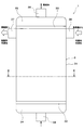
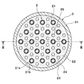
- the adsorber 1 includes an adsorbing core 2 in a housing 3 as shown in FIGS.
- the adsorption core 2 has a heat medium pipe 21 through which a heat medium (refrigerant) flows, and a porous heat transfer body 23 having pores and an adsorbent 24 are provided in a peripheral portion 22 of the heat medium pipe 21. Yes.
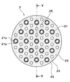
- the adsorption core 2 is filled in the heat medium pipe 21, the porous heat transfer body 23 having the pores 23 a, and the pores 23 a. And an adsorbent 24.
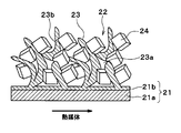
- the heat medium pipe 21 is made of a core material 21 a made of a metal (stainless steel in the present embodiment) harder than copper, and copper or a copper alloy (copper in the present embodiment). And a coating layer 21b that covers the outer surface of the core material 21a.
- the coating layer 21b is formed by performing copper plating on the outer surface of the core material 21a.
- the porous heat transfer body 23 is a sintered body in which the copper powder 23b having excellent thermal conductivity is heated and bonded by sintering without melting.
- the copper powder 23b uses copper or a copper alloy (in this embodiment, copper).
- the copper powder is powdery, particulate, scaly, or fibrous (in this embodiment, fibrous. ) May be used.
- so-called three-dimensional network pores are formed in the sintered body due to the voids existing between the copper powders 23b.
- the three-dimensional network pores correspond to the pores 23a.
- the above-mentioned “bonding by sintering without melting” is to fuse the vicinity of the surface layer of the copper powder 23b. That is, at the time of sintering, voids (pores) existing between the copper powders 23b are left as they are, and the contact portions between the copper powders 23b are metallicly bonded.
- the pores 23a are fine pores configured to be able to be filled with the adsorbent 24 having a fine particle diameter.
- the copper powder 23b (porous heat transfer body 23) is metallically bonded to the coating layer 21b of the heat medium tube 21 by sintering.
- the porous heat transfer body 23 is formed in the peripheral portion 22 of the plurality of cylindrical heat medium pipes 21 so that the whole extends in one direction. As shown in FIG. is there.
- the adsorbent 24 adsorbs the gas phase fluid (water vapor) outside the heat medium pipe 21 by being cooled by the heat medium, and further adsorbs the fluid (water vapor) adsorbed by being heated. Detach.
- the adsorbent 24 is formed into a number of minute particles, and is made of, for example, silica gel or zeolite.
- the adsorbent 24 is filled in the pores 23 a of the porous heat transfer body 23.
- an adsorbed medium passage 25 through which an adsorbed medium (hereinafter, water vapor) flows is disposed between the heat medium tubes 21.
- the adsorbed medium passage 25 is formed to extend, for example, straight in one direction.
- the adsorbed medium passage 25 is formed so as to extend in the extending direction of the heat medium pipe 21, that is, in the axial direction of the columnar heat medium pipe 21.
- the adsorber 1 includes an adsorption core 2 and a housing 3 made of metal.
- the housing 3 is made of copper or a copper alloy.
- the housing 3 includes a housing body 31, sheets 32 and 33, and tanks 34 and 35.
- the housing body 31 is formed in a cylindrical shape, and is formed so that the porous heat transfer body 23 of the columnar adsorption core 2 can be accommodated therein. Moreover, the opening part of the upper end side and lower end side of the housing body 31 is formed so as to be able to be sealed by sheets 32 and 33, respectively.
- An adsorbed medium inflow pipe 36 and an adsorbed medium outflow pipe 37 capable of guiding water vapor to the above-described adsorbent filling portion (adsorbent filled layer) of the adsorbing core 2 are provided on the upper portion of the housing body 31. Is provided.
- water vapor is distributed to the adsorbed medium passage 25 from the evaporator side through the adsorbed medium inflow pipe 36.
- the water vapor distributed to the adsorbed medium passage 25 penetrates into the adsorbent packed bed.
- water vapor is discharged from the adsorbent packed bed, and the discharged water vapor is guided to the condenser side from the adsorbed medium outflow pipe 37 through each adsorbed medium passage 25.
- the sheets 32 and 33 are formed with through holes 32a and 33a through which the heat medium pipe 21 can pass.
- the through holes 32a and 33a and the heat medium pipe 21 are airtightly fixed by joining by brazing or the like.
- the tanks 34 and 35 are provided with a heat medium inflow pipe 38 and a heat medium outflow pipe 39 capable of guiding the heat medium.
- the heat medium flows into the heat medium inflow pipe 38 of the lower tank 34, flows out of the heat medium outflow pipe 39 of the upper tank 35 through the heat medium pipe 21.
- the lower tank 34 and the upper tank 35 are tanks for supplying and distributing the heat exchange medium to the plurality of heat medium tubes 21.
- a method for manufacturing the adsorber 1 of this embodiment will be described.
- a plating step of performing copper plating on the outer surface of the stainless steel core material 21a formed in a cylindrical shape is performed.
- tube 21 which has the coating layer 21b which consists of copper on the outer surface of the core material 21a is formed.
- a sintering step is performed in which the copper powder 23b and the adsorbent 24 are sintered on the peripheral portion 22 of the heat medium tube 21. Specifically, after the heat medium pipe 21 is held and fixed in the casing 3, the casing 3 is filled with the copper powder 23 b and the adsorbent 24. And all the components of the adsorber 1 which require brazing coupling
- brazing joining (joining) of the parts which comprise the adsorption machine 1 sintering of the copper powder 23b with which the housing
- tube 21 Specifically, the sinter bonding (bonding) with the coating layer 21b) and the fixing of the adsorbent 24 inside the sintered body (porous heat transfer body 23) are performed.
- the rigidity of the heat medium tube 21 can be improved by configuring the core material 21a of the heat medium tube 21 from stainless steel, which is a metal having higher hardness than copper.
- the coating layer 21b made of copper is provided on the outer surface of the core material 21a of the heat medium tube 21, and the copper powder 23b is coated with the copper by coating the copper powder 23b and the heat medium tube 21 with the coating layer 21b made of copper.
- the plate thickness of the heat medium pipe 21 is about 0.6 to 1 mm in consideration of corrosion resistance. It is common to do. However, when the plate thickness of the heat medium pipe 21 is increased, the heat capacity increases, so that a high coefficient of performance (COP) cannot be exhibited as the entire refrigeration cycle of the adsorption refrigeration apparatus.
- COP coefficient of performance
- the core material 21a of the heat medium tube 21 is made of stainless steel, which is a metal having higher hardness than copper. Therefore, the plate thickness of the heat medium tube 21 is reduced and the heat capacity is reduced. can do. For this reason, it becomes possible to improve a coefficient of performance (COP) as the whole refrigeration cycle of the adsorption refrigeration apparatus.
- COP coefficient of performance
- the conventional adsorption core 2 in which the heat medium pipe 21 is made of copper may cause erosion and corrosion when the flow rate of the heat medium flowing through the heat medium pipe 21 is high.
- the core material 21a of the heat medium pipe 21 is made of stainless steel, which is a metal having a hardness higher than that of copper, so that the occurrence of erosion and corrosion can be suppressed.
- the porous heat transfer body 23 needs to be provided with the pores 23a through which water vapor as the adsorbed medium flows. For this reason, the porous heat transfer body 23 must be formed in a state where a very large porosity is maintained. In order to form the porous heat transfer body 23 having such a high porosity, it is necessary to prevent pressure from being applied from the surroundings in the sintering process. However, in the case where the heat medium tube 21 is made of a metal other than copper, the porous heat transfer body 23 (copper powder 23b) and There is a possibility that the bondability with the heat medium pipe 21 is deteriorated.
- the coating layer 21b made of copper on the outer surface of the heat medium pipe 21, the coating layer 21b made of copper and the copper powder 23b can be favorably metal-bonded. . Therefore, even if a metal other than copper is used as the core material 21 a of the heat medium pipe 21, it is possible to improve the bonding property between the porous heat transfer body 23 and the heat medium pipe 21.
- the outer surface of the coating layer 21b of the heat medium pipe 21 is roughened, that is, the roughening process is performed so that the outer surface of the coating layer 21b becomes rough. (Unevenness is formed).
- a roughening step of roughening the outer surface of the coating layer 21b of the heat medium tube 21 is performed after the plating step and before the sintering step.
- a method for roughening the outer surface of the coating layer 21b of the heat medium tube 21 for example, a method such as grinding with a file, shot blasting, etching, or covering the surface of the coating layer 21b with copper powder can be employed.
- the contact surface between the coating layer 21b and the copper powder 23b is increased by roughening the outer surface of the coating layer 21b of the heat medium pipe 21. Can do. For this reason, the heat transfer performance between the heat medium pipe 21 and the porous heat transfer body 23 can be improved.
- the core material 21a of the heat medium pipe 21 is made of stainless steel.
- it may be made of any metal as long as it is a metal harder than copper, such as titanium.
Landscapes
- Engineering & Computer Science (AREA)
- Physics & Mathematics (AREA)
- Mechanical Engineering (AREA)
- Thermal Sciences (AREA)
- General Engineering & Computer Science (AREA)
- Chemical & Material Sciences (AREA)
- Chemical Kinetics & Catalysis (AREA)
- General Chemical & Material Sciences (AREA)
- Sorption Type Refrigeration Machines (AREA)
- Powder Metallurgy (AREA)
Abstract
内部を熱媒体が流通する熱媒体管(21)と、熱媒体によって冷却されることで熱媒体管(21)外部の水蒸気を吸着し、さらに、加熱されることで吸着した水蒸気を脱離する吸着剤(24)とを備える吸着コアにおいて、熱媒体管(21)は、銅よりも硬度の高い金属からなる芯材(21a)と、銅からなるとともに芯材(21a)の外表面を被覆する被覆層(21b)とを有しており、熱媒体管(21a)の周辺部(22)に、銅粉(23b)および吸着剤(24)の混合焼結体が設けられており、銅粉(23b)と熱媒体管(21)とが金属接合されている。これにより、熱媒体管と吸着剤との間の伝熱性能を向上させつつ、熱媒体管の剛性を高くすることができる。
Description
本出願は、当該開示内容が参照によって本出願に組み込まれた、2013年11月29日に出願された日本特許出願2013-247709号を基にしている。
本開示は、流体の吸着および脱離を行う吸着剤を有する吸着コアおよびその製造方法に関するものである。
従来、吸着式冷凍機等に用いられる吸着コアとして、熱媒体が流れる複数の熱媒体管を有し、熱媒体管の周辺部に多孔質伝熱体である金属粉および吸着剤が設けられたものが開示されている(例えば、特許文献1参照)。この吸着コアでは、金属粉が熱媒体管に金属的に接合されている。
本開示の発明者等による検討によれば、上記特許文献1に記載のような構成の吸着コアでは、安価に混合焼結でき、熱伝導性も高い銅粉を金属粉として用いることが考えられる。この場合、熱媒体管は銅粉と金属的に接合されるため、熱媒体管を銅により構成する必要がある。
しかしながら、熱媒体管を銅製とすると、焼結時に銅が柔らかくなり、熱媒体管の剛性が低くなるため、振動に弱くなるとともに、手扱いが困難になる恐れがある。これにより、吸着コアの大型化および長尺化が困難となる。
本開示は上記点に鑑みて、熱媒体管と吸着剤との間の伝熱性能を向上させつつ、熱媒体管の剛性を高くすることができる吸着コアおよびその製造方法を提供することを目的とする。
本開示の第1の態様では、内部を熱媒体が流通する熱媒体管と、熱媒体によって冷却されることで熱媒体管外部の気相状態の流体を吸着し、さらに、加熱されることで吸着した流体を脱離する吸着剤とを備える吸着コアにおいて、熱媒体管は、銅よりも硬度の高い金属からなる芯材と、銅からなるとともに芯材の外表面を被覆する被覆層とを有しており、熱媒体管の周辺部に、銅粉および吸着剤の混合焼結体が設けられており、銅粉と熱媒体管とが金属接合されている。
これによれば、熱媒体管の芯材を銅よりも硬度の高い金属から構成することで、熱媒体管の剛性を向上させることができる。
また、熱媒体管の周辺部に銅粉および吸着剤の混合焼結体を設けることで、熱媒体管と吸着剤との間の伝熱手段として、熱伝導性の高い銅粉が用いられるので、熱媒体管と吸着剤との間の伝熱性能を向上させることができる。
さらに、熱媒体管の芯材の外表面に銅からなる被覆層を設けるとともに、銅粉と熱媒体管とを金属接合させることで、銅粉を銅からなる被覆層に金属接合させることができる。これにより、混合焼結体と熱媒体管の界面の熱抵抗を飛躍的に低減することができるため、熱媒体管と吸着剤との間の伝熱性能を確実に向上させることができる。
以上により、熱媒体管と吸着剤との間の伝熱性能を向上させつつ、熱媒体管の剛性を高くすることが可能となる。
また、本開示の第2の態様では、内部を熱媒体が流通する熱媒体管と、熱媒体によって冷却されることで熱媒体管外部の気相状態の流体を吸着し、さらに、加熱されることで吸着した流体を脱離する吸着剤とを備える吸着コアの製造方法において、銅よりも硬度の高い金属からなる芯材を有する熱媒体管の外表面に、銅メッキを施すことにより銅からなる被覆層を形成するメッキ工程と、メッキ工程の後、熱媒体管の周辺部に銅粉および吸着剤を焼結する焼結工程とを含んでおり、焼結工程では、銅粉と熱媒体管とを金属接合する。
これによれば、銅よりも硬度の高い金属からなる芯材を有する熱媒体管を用いることで、熱媒体管の剛性を向上させることができる。
また、熱媒体管の周辺部に銅粉および吸着剤を焼結する焼結工程を設けているので、熱媒体管と吸着剤との間の伝熱手段として、熱伝導性の高い銅粉を用いることができる。これにより、熱媒体管と吸着剤との間の伝熱性能を向上させることができる。
さらに、焼結工程において、銅粉と熱媒体管とを金属接合することで、銅粉を銅からなる被覆層に金属接合することができる。これにより、混合焼結体と熱媒体管の界面の熱抵抗を飛躍的に低減することができるため、熱媒体管と吸着剤との間の伝熱性能を確実に向上させることができる。
以上により、熱媒体管と吸着剤との間の伝熱性能を向上させつつ、熱媒体管の剛性を高くできる吸着コアを提供することが可能となる。
なお、本開示における「銅」とは、純銅および銅合金のいずれをも含むものである。
以下、本開示の実施形態について図に基づいて説明する。尚、各実施形態において対応する構成要素には同一の符号を付すことにより、重複する説明を省略する場合がある。各実施形態において構成の一部分のみを説明している場合、当該構成の他の部分については、先行して説明した他の実施形態の構成を適用することができる。また、各実施形態の説明において明示している構成の組み合わせばかりではなく、特に組み合わせに支障が生じなければ、明示していなくても複数の実施形態の構成同士を部分的に組み合せることができる。
(第1実施形態)
本開示の第1実施形態に係る吸着コアを備える吸着器について、図1から図6に基づいて説明する。図1に示すように、本実施形態の吸着器1は、その内部に含む吸着剤が気相状態の流体(本実施形態では水蒸気)を吸着する作用を用いて流体を蒸発させ、その蒸発潜熱により冷凍能力を発揮する吸着式冷凍機に搭載される。吸着器1は、車両用などの空調装置に適用することもできる。
本開示の第1実施形態に係る吸着コアを備える吸着器について、図1から図6に基づいて説明する。図1に示すように、本実施形態の吸着器1は、その内部に含む吸着剤が気相状態の流体(本実施形態では水蒸気)を吸着する作用を用いて流体を蒸発させ、その蒸発潜熱により冷凍能力を発揮する吸着式冷凍機に搭載される。吸着器1は、車両用などの空調装置に適用することもできる。
この吸着器1は、図2および図3に示すように、筐体3内に吸着コア2を備えている。吸着コア2は、熱媒体(冷媒)が流れる熱媒体管21を有しており、熱媒体管21の周辺部22に、細孔を有する多孔質伝熱体23および吸着剤24が設けられている。
具体的には、吸着コア2は、図4、図5および図6に示すように、熱媒体管21と、細孔23aを有する多孔質伝熱体23と、その細孔23aに充填された吸着剤24とを有している。
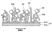
図6に示すように、熱媒体管21は、材質が銅よりも硬質な金属(本実施形態では、ステンレス)からなる芯材21aと、銅または銅合金(本実施形態では、銅)からなるとともに芯材21aの外表面を被覆する被覆層21bとを有している。被覆層21bは、芯材21aの外表面に銅メッキを施すことにより形成されている。
多孔質伝熱体23は、熱伝導性に優れる銅粉23bを加熱して、溶融することなく焼結によって結合した焼結体である。銅粉23bは、銅または銅合金(本実施形態では、銅)を用いており、例えばその銅粉は、粉末状、粒子状、鱗片状および繊維状のいずれか(本実施形態では、繊維状)に形成されているものであればよい。
上記焼結時においては、銅粉23b間に存在する空隙によって、いわゆる三次元網目状の気孔が焼結体に形成される。この三次元網目状の気孔が、上記細孔23aに相当するものである。なお、上述した「溶融することなく焼結によって結合」とは、銅粉23bの表層付近を融着させることである。すなわち、焼結時において、銅粉23b間に存在する空隙(細孔)をそのまま残し、銅粉23b間の接触箇所が金属的に結合する。
細孔23aは、粒子径が微小な吸着剤24を充填可能に構成された微細な孔である。銅粉23b(多孔質伝熱体23)は、熱媒体管21の被覆層21bに焼結によって金属的に結合している。多孔質伝熱体23は、その全体が一方向に伸長するように、複数の円筒状の熱媒体管21の周辺部22に形成されており、図4に示すように全体形状として円柱状である。
図6に戻り、吸着剤24は、熱媒体によって冷却されることで熱媒体管21外部の気相状態の流体(水蒸気)を吸着し、さらに、加熱されることで吸着した流体(水蒸気)を脱離するものである。吸着剤24は、微小な多数の粒子状に形成されており、例えば、シリカゲル、ゼオライトから構成されている。吸着剤24は、多孔質伝熱体23の細孔23a内部に充填されている。
さらに、本実施形態では、図4および図5に示すように、熱媒体管21の間に、被吸着媒体(以下、水蒸気)が流通する被吸着媒体通路25が配置されている。この被吸着媒体通路25は、上記三次元網目状の細孔23aとは異なり、一方向に例えばまっすぐに延びるように形成されている。具体的には、被吸着媒体通路25は、熱媒体管21の延伸方向、すなわち円柱状の熱媒体管21の軸方向に延びるように形成されている。
次に、上述した構成の吸着コア2を筐体3内部に一体成形した吸着器1を、図1~図3に基づいて説明する。
吸着器1は、吸着コア2と、金属からなる筐体3とを備えている。なお、本実施例では、筐体3は、銅または銅合金から構成されている。筐体3は、筐体本体31、シート32、33、およびタンク34、35を有している。
筐体本体31は、円筒状に形成されており、内部に、円柱状の吸着コア2の多孔質伝熱体23が収容可能に形成されている。また、筐体本体31の上端側および下端側の開口部は、それぞれシート32、33で封止可能に形成されている。筐体本体31の上部には、吸着コア2の上述した吸着剤を充填する部分(吸着剤充填層)に、水蒸気を導くことが可能な被吸着媒体流入配管36および被吸着媒体流出配管37が設けられている。
このように筐体本体31とシート32、33を封止することにより、内部を真空に保持可能である。これにより、筐体本体31とシート32、33によって形成される内部密閉空間には、被吸着媒体としての水蒸気以外には、他の気体は存在しないようになっている。
吸着時には、水蒸気は、蒸発器側から被吸着媒体流入配管36を通して、被吸着媒体通路25に分配される。被吸着媒体通路25に分配された水蒸気は、吸着剤充填層の内部に浸透する。また、脱離時には、水蒸気は、吸着剤充填層から吐き出され、吐き出された水蒸気は各被吸着媒体通路25を通して、被吸着媒体流出配管37より凝縮器側へ導かれる。
また、シート32、33には、熱媒体管21が貫通可能な貫通穴32a、33aが形成されている。この貫通穴32a、33aと熱媒体管21は、ろう付け等による接合により気密に固定されている。
タンク34、35には、熱媒体を導くことが可能な熱媒体流入配管38および熱媒体流出配管39が設けられている。熱媒体は、下部タンク34の熱媒体流入配管38に流入し、熱媒体管21を通して、上部タンク35の熱媒体流出配管39より流出する。このような下部タンク34および上部タンク35は、熱交換媒体を複数の熱媒体管21へ供給分配するためのタンクである。
次に、本実施形態の吸着器1の製造方法について説明する。まず、円筒状に形成されたステンレス製の芯材21aの外表面に、銅メッキを施すメッキ工程を行う。これにより、芯材21aの外表面に銅からなる被覆層21bを有する熱媒体管21が形成される。
続いて、熱媒体管21の周辺部22に銅粉23bおよび吸着剤24を焼結する焼結工程を行う。具体的には、熱媒体管21を筐体3内に保持させて固定した後、筐体3内に銅粉23bおよび吸着剤24を充填する。そして、ろう付け結合(接合)が必要となる吸着器1の構成部品をすべて組み付け、その組み付け体を加熱炉に搬入する。これにより、吸着器1を構成する部品同士のろう付け結合(接合)と、筐体3内に充填された銅粉23bの焼結と、この銅粉23bの焼結体と熱媒体管21(詳細には被覆層21b)との焼結結合(接合)と、吸着剤24の焼結体(多孔質伝熱体23)内部への定着とが行われる。
以上説明したように、熱媒体管21の芯材21aを、銅よりも硬度の高い金属であるステンレスから構成することで、熱媒体管21の剛性を向上させることができる。
また、熱媒体管21の周辺部22に銅粉23bおよび吸着剤24の混合焼結体を設けることで、熱媒体管21と吸着剤24との間の伝熱手段として、熱伝導性の高い銅粉23bが用いられるので、熱媒体管21と吸着剤24との間の伝熱性能を向上させることができる。
さらに、熱媒体管21の芯材21aの外表面に銅からなる被覆層21bを設けるとともに、銅粉23bと熱媒体管21とを金属接合させることで、銅粉23bを銅からなる被覆層21bに金属接合させることができる。これにより、混合焼結体(多孔質伝熱体23)と熱媒体管21の界面の熱抵抗を飛躍的に低減することができるため、熱媒体管21と吸着剤24との間の伝熱性能を確実に向上させることができる。
以上により、熱媒体管21と吸着剤24との間の伝熱性能を向上させつつ、熱媒体管21の剛性を高くすることが可能となる。
ところで、熱媒体管21を銅製とした従来の吸着コア2において、熱媒体として水道水を採用した場合、耐腐食性を考慮して、熱媒体管21の板厚を0.6~1mm程度とするのが一般的である。しかしながら、熱媒体管21の板厚を厚くすると熱容量が大きくなるため、吸着式冷凍装置の冷凍サイクル全体として高い成績係数(COP)を発揮することができない。
これに対し、本実施形態では、熱媒体管21の芯材21aを、銅よりも硬度の高い金属であるステンレスから構成しているので、熱媒体管21の板厚を薄くし、熱容量を小さくすることができる。このため、吸着式冷凍装置の冷凍サイクル全体として成績係数(COP)を向上させることが可能となる。
ところで、銅は軟質の金属であるため、熱媒体管21を銅製とした従来の吸着コア2では、熱媒体管21内を流れる熱媒体の流速が速いとき、エロージョンおよびコロージョンが生じるおそれがある。
これに対し、本実施形態では、熱媒体管21の芯材21aを、銅よりも硬度の高い金属であるステンレスから構成しているので、エロージョンおよびコロージョンの発生を抑制できる。
ところで、上述したように、多孔質伝熱体23には、被吸着媒体である水蒸気が流通する細孔23aを設ける必要がある。このため、多孔質伝熱体23は、非常に大きい空隙率を保った状態で形成されなければならない。このような空隙率の高い多孔質伝熱体23を形成するためには、焼結工程において周囲から圧力を加えないようにする必要がある。しかしながら、熱媒体管21が銅以外の金属から構成されている場合、焼結工程において多孔質伝熱体23の周囲から圧力が加えられないと、多孔質伝熱体23(銅粉23b)と熱媒体管21との接合性が悪化するおそれがある。
これに対し、本実施形態のように、熱媒体管21の外表面に銅からなる被覆層21bを設けることで、銅からなる被覆層21bと銅粉23bとを良好に金属接合することができる。したがって、熱媒体管21の芯材21aとして銅以外の金属が用いられていても、多孔質伝熱体23と熱媒体管21との接合性を向上させることが可能となる。
(第2実施形態)
次に、本開示の第2実施形態について図7に基づいて説明する。図7に示すように、本第2実施形態では、熱媒体管21の被覆層21bの外表面が荒らされている、すなわち被覆層21bの外表面が粗くなるよう粗し処理が施されている(凸凹が形成されている)。
次に、本開示の第2実施形態について図7に基づいて説明する。図7に示すように、本第2実施形態では、熱媒体管21の被覆層21bの外表面が荒らされている、すなわち被覆層21bの外表面が粗くなるよう粗し処理が施されている(凸凹が形成されている)。
具体的な粗し処理としては、メッキ工程の後、かつ、焼結工程の前に、熱媒体管21の被覆層21bの外表面を粗くする粗化工程が行われる。熱媒体管21の被覆層21bの外表面を粗くする方法としては、例えば、ヤスリ等による研削、ショットブラスト、エッチング、被覆層21bの表面に銅粉をまぶす等の方法を採用することができる。
本実施形態のように、熱媒体管21の被覆層21bの外表面に粗し処理を施すことで、被覆層21bと銅粉23b(多孔質伝熱体23)との接触面積を増加させることができる。このため、熱媒体管21と多孔質伝熱体23との間の伝熱性能を向上させることができる。
(他の実施形態)
本開示は上述の実施形態に限定されることなく、本開示の趣旨を逸脱しない範囲内で、以下のように種々変形可能である。
本開示は上述の実施形態に限定されることなく、本開示の趣旨を逸脱しない範囲内で、以下のように種々変形可能である。
(1)上記実施形態では、熱媒体管21の芯材21aをステンレスにより構成した例について説明したが、例えばチタン等、銅より硬質な金属であれば任意の金属により構成してもよい。
(2)上記実施形態では、熱媒体管21および筐体3の径方向断面を円筒形状とした例について説明したが、これに限らず、熱媒体管および筐体の径方向断面を、楕円形状、矩形状等のいずれの形状としてもよい。
Claims (5)
- 内部を熱媒体が流通する熱媒体管(21)と、
前記熱媒体によって冷却されることで前記熱媒体管(21)外部の気相状態の流体を吸着し、さらに、加熱されることで吸着した前記流体を脱離する吸着剤(24)とを備える吸着コアであって、
前記熱媒体管(21)は、銅よりも硬度の高い金属からなる芯材(21a)と、銅からなるとともに前記芯材(21a)の外表面を被覆する被覆層(21b)とを有しており、
前記熱媒体管(21)の周辺部(22)に、銅粉(23b)および前記吸着剤(24)の混合焼結体が設けられており、
前記銅粉(23b)と前記熱媒体管(21)とが金属接合されている吸着コア。 - 前記被覆層(21b)の外表面に粗し処理が施こされている請求項1に記載の吸着コア。
- 前記芯材(21a)は、ステンレスからなる請求項1または2に記載の吸着コア。
- 内部を熱媒体が流通する熱媒体管(21)と、
前記熱媒体によって冷却されることで前記熱媒体管(21)外部の気相状態の流体を吸着し、さらに、加熱されることで吸着した前記流体を脱離する吸着剤(24)とを備える吸着コアの製造方法であって、
銅よりも硬度の高い金属からなる芯材(21a)を有する熱媒体管(21)の外表面に、銅メッキを施すことにより銅からなる被覆層(21b)を形成するメッキ工程と、
前記メッキ工程の後、前記熱媒体管(21)の周辺部(22)に銅粉(23b)および前記吸着剤(24)を焼結する焼結工程とを含んでおり、
前記焼結工程では、前記銅粉(23b)と前記熱媒体管(21)とを金属接合する吸着コアの製造方法。 - 前記メッキ工程の後、かつ、前記焼結工程の前に、前記被覆層(21b)の外表面を粗くする工程を含んでいる請求項4に記載の吸着コアの製造方法。
Priority Applications (3)
| Application Number | Priority Date | Filing Date | Title |
|---|---|---|---|
| DE112014005460.7T DE112014005460B4 (de) | 2013-11-29 | 2014-11-28 | Adsorptionskern und Herstellungsverfahren dafür |
| US15/039,069 US10591189B2 (en) | 2013-11-29 | 2014-11-28 | Adsorption core and manufacturing method thereof |
| CN201480065074.1A CN105992919B (zh) | 2013-11-29 | 2014-11-28 | 吸附芯及其制造方法 |
Applications Claiming Priority (2)
| Application Number | Priority Date | Filing Date | Title |
|---|---|---|---|
| JP2013-247709 | 2013-11-29 | ||
| JP2013247709A JP6146282B2 (ja) | 2013-11-29 | 2013-11-29 | 吸着コアおよびその製造方法 |
Publications (1)
| Publication Number | Publication Date |
|---|---|
| WO2015079704A1 true WO2015079704A1 (ja) | 2015-06-04 |
Family
ID=53198666
Family Applications (1)
| Application Number | Title | Priority Date | Filing Date |
|---|---|---|---|
| PCT/JP2014/005954 Ceased WO2015079704A1 (ja) | 2013-11-29 | 2014-11-28 | 吸着コアおよびその製造方法 |
Country Status (5)
| Country | Link |
|---|---|
| US (1) | US10591189B2 (ja) |
| JP (1) | JP6146282B2 (ja) |
| CN (1) | CN105992919B (ja) |
| DE (1) | DE112014005460B4 (ja) |
| WO (1) | WO2015079704A1 (ja) |
Families Citing this family (7)
| Publication number | Priority date | Publication date | Assignee | Title |
|---|---|---|---|---|
| EP3382314A1 (en) * | 2017-03-30 | 2018-10-03 | Nederlandse Organisatie voor toegepast- natuurwetenschappelijk onderzoek TNO | Enhanced tcm production and use |
| WO2019097436A1 (en) * | 2017-11-15 | 2019-05-23 | Banaei Amirhosein | Thermal energy storage system |
| CN109556310B (zh) * | 2018-10-09 | 2021-03-30 | 宁波工程学院 | 吸附制冷器具 |
| FR3100876B1 (fr) * | 2019-09-12 | 2021-09-03 | Ifp Energies Now | Dispositif multitubulaire de stockage thermique par sorption sur zéolithe par contact direct |
| CN114646227B (zh) * | 2020-12-21 | 2023-12-05 | 浙江盾安人工环境股份有限公司 | 绕管式换热器及具有其的制冷系统 |
| PL4256267T3 (pl) * | 2022-01-28 | 2024-08-05 | Bernhard König | Termochemiczne magazynowanie energii oraz system wyposażony w termochemiczny magazyn energii |
| US12407044B1 (en) * | 2024-07-12 | 2025-09-02 | Hillary Horvat | Zeolite battery heater |
Citations (4)
| Publication number | Priority date | Publication date | Assignee | Title |
|---|---|---|---|---|
| JP2005111425A (ja) * | 2003-10-10 | 2005-04-28 | Daikin Ind Ltd | 吸着素子および調湿装置 |
| JP2008107075A (ja) * | 2006-09-29 | 2008-05-08 | Denso Corp | 吸着モジュールおよび吸着モジュールの製造方法 |
| JP2011196661A (ja) * | 2010-03-23 | 2011-10-06 | Toyota Central R&D Labs Inc | 蓄熱器 |
| WO2013001390A1 (en) * | 2011-06-30 | 2013-01-03 | International Business Machines Corporation | Adsorption heat exchanger devices |
Family Cites Families (5)
| Publication number | Priority date | Publication date | Assignee | Title |
|---|---|---|---|---|
| JPS602677A (ja) * | 1983-06-20 | 1985-01-08 | Matsushita Refrig Co | 熱交換器用管の製造方法 |
| US7715133B2 (en) * | 2006-07-06 | 2010-05-11 | An Chen Computer Co., Ltd. | Method for duplicating data |
| CN101144664B (zh) * | 2007-10-18 | 2010-05-19 | 华东理工大学 | 烧结型沸石分子筛吸附制冷单元管的制备工艺 |
| CN201145447Y (zh) * | 2007-12-19 | 2008-11-05 | 华东理工大学 | 基于烧结多孔材料的吸附式制冷装置 |
| CN203036102U (zh) * | 2013-01-08 | 2013-07-03 | 无锡市石油化工设备有限公司 | 金属复合管 |
-
2013
- 2013-11-29 JP JP2013247709A patent/JP6146282B2/ja not_active Expired - Fee Related
-
2014
- 2014-11-28 CN CN201480065074.1A patent/CN105992919B/zh not_active Expired - Fee Related
- 2014-11-28 DE DE112014005460.7T patent/DE112014005460B4/de not_active Expired - Fee Related
- 2014-11-28 WO PCT/JP2014/005954 patent/WO2015079704A1/ja not_active Ceased
- 2014-11-28 US US15/039,069 patent/US10591189B2/en not_active Expired - Fee Related
Patent Citations (4)
| Publication number | Priority date | Publication date | Assignee | Title |
|---|---|---|---|---|
| JP2005111425A (ja) * | 2003-10-10 | 2005-04-28 | Daikin Ind Ltd | 吸着素子および調湿装置 |
| JP2008107075A (ja) * | 2006-09-29 | 2008-05-08 | Denso Corp | 吸着モジュールおよび吸着モジュールの製造方法 |
| JP2011196661A (ja) * | 2010-03-23 | 2011-10-06 | Toyota Central R&D Labs Inc | 蓄熱器 |
| WO2013001390A1 (en) * | 2011-06-30 | 2013-01-03 | International Business Machines Corporation | Adsorption heat exchanger devices |
Also Published As
| Publication number | Publication date |
|---|---|
| CN105992919B (zh) | 2018-10-16 |
| DE112014005460T5 (de) | 2016-08-25 |
| JP2015105778A (ja) | 2015-06-08 |
| US20170038101A1 (en) | 2017-02-09 |
| CN105992919A (zh) | 2016-10-05 |
| JP6146282B2 (ja) | 2017-06-14 |
| US10591189B2 (en) | 2020-03-17 |
| DE112014005460B4 (de) | 2021-03-11 |
Similar Documents
| Publication | Publication Date | Title |
|---|---|---|
| WO2015079704A1 (ja) | 吸着コアおよびその製造方法 | |
| JP6436557B2 (ja) | 吸着式冷凍機 | |
| US20090217691A1 (en) | Adsorption Heat Pump, Adsorption Refrigerator and Adsorber Elements Therefor | |
| JP4985337B2 (ja) | 吸着式ヒートポンプ装置 | |
| JP5445492B2 (ja) | 吸着器 | |
| US9435573B2 (en) | Adsorption heat pump | |
| US10780389B2 (en) | Magnetic desiccant bag | |
| CN113048822B (zh) | 热管、电子设备及热管的加工方法 | |
| JP6011499B2 (ja) | 吸着器 | |
| JP4380620B2 (ja) | 吸着コア、吸着コアの製造方法および吸着式冷凍機 | |
| JP4821563B2 (ja) | 吸着モジュールおよび吸着モジュールの製造方法 | |
| CN107850357A (zh) | 吸附器、用于制造吸附器的方法和具有吸附器的车辆 | |
| JP2009097733A (ja) | 吸着熱交換器とその製造方法 | |
| JP4760669B2 (ja) | 吸着モジュールおよび吸着モジュールの製造方法 | |
| JP4830799B2 (ja) | 吸着モジュール | |
| JP4821746B2 (ja) | 吸着熱交換器 | |
| EP3803233B1 (en) | Water-cooled heat exchanger | |
| JP5315893B2 (ja) | 吸着式ヒートポンプ | |
| JP6384029B2 (ja) | 熱交換器構造体 | |
| JP7564047B2 (ja) | 熱交換器及び冷凍サイクル装置 | |
| JP2009121711A (ja) | 吸着熱交換器 | |
| JP2008070005A (ja) | 吸着器および吸着器の製造方法 | |
| JP2006200870A (ja) | 吸着式冷凍機用吸着器及びその吸着式冷凍機用吸着器の製造方法 | |
| JP2007070128A (ja) | 吸着素子の製造方法、吸着素子、水熱合成装置 |
Legal Events
| Date | Code | Title | Description |
|---|---|---|---|
| 121 | Ep: the epo has been informed by wipo that ep was designated in this application |
Ref document number: 14865576 Country of ref document: EP Kind code of ref document: A1 |
|
| WWE | Wipo information: entry into national phase |
Ref document number: 15039069 Country of ref document: US |
|
| WWE | Wipo information: entry into national phase |
Ref document number: 112014005460 Country of ref document: DE |
|
| 122 | Ep: pct application non-entry in european phase |
Ref document number: 14865576 Country of ref document: EP Kind code of ref document: A1 |