WO2015076185A1 - 蓋部材開閉機構及び基板検査装置 - Google Patents
蓋部材開閉機構及び基板検査装置 Download PDFInfo
- Publication number
- WO2015076185A1 WO2015076185A1 PCT/JP2014/080129 JP2014080129W WO2015076185A1 WO 2015076185 A1 WO2015076185 A1 WO 2015076185A1 JP 2014080129 W JP2014080129 W JP 2014080129W WO 2015076185 A1 WO2015076185 A1 WO 2015076185A1
- Authority
- WO
- WIPO (PCT)
- Prior art keywords
- groove
- lid member
- main body
- guide
- closing mechanism
- Prior art date
- Legal status (The legal status is an assumption and is not a legal conclusion. Google has not performed a legal analysis and makes no representation as to the accuracy of the status listed.)
- Ceased
Links
Images



Classifications
-
- G—PHYSICS
- G01—MEASURING; TESTING
- G01R—MEASURING ELECTRIC VARIABLES; MEASURING MAGNETIC VARIABLES
- G01R31/00—Arrangements for testing electric properties; Arrangements for locating electric faults; Arrangements for electrical testing characterised by what is being tested not provided for elsewhere
- G01R31/26—Testing of individual semiconductor devices
- G01R31/2601—Apparatus or methods therefor
-
- G—PHYSICS
- G01—MEASURING; TESTING
- G01R—MEASURING ELECTRIC VARIABLES; MEASURING MAGNETIC VARIABLES
- G01R31/00—Arrangements for testing electric properties; Arrangements for locating electric faults; Arrangements for electrical testing characterised by what is being tested not provided for elsewhere
- G01R31/28—Testing of electronic circuits, e.g. by signal tracer
- G01R31/2851—Testing of integrated circuits [IC]
- G01R31/2893—Handling, conveying or loading, e.g. belts, boats, vacuum fingers
-
- G—PHYSICS
- G01—MEASURING; TESTING
- G01R—MEASURING ELECTRIC VARIABLES; MEASURING MAGNETIC VARIABLES
- G01R1/00—Details of instruments or arrangements of the types included in groups G01R5/00 - G01R13/00 and G01R31/00
- G01R1/02—General constructional details
- G01R1/04—Housings; Supporting members; Arrangements of terminals
Definitions
- the present invention relates to a lid member opening / closing mechanism and a substrate inspection device for maintaining the state of a lid member of a substrate inspection device having a casing-like main body in an open state and a closed state, respectively.
- a prober is known as an apparatus for inspecting the electrical characteristics of a semiconductor device such as a power device or a memory formed on a semiconductor wafer (hereinafter simply referred to as “wafer”) as a substrate.
- the prober includes a disk-shaped probe card having a large number of probe needles, a stage on which a wafer is placed and moved freely up and down, left and right, and a casing-like main body containing the stage.
- Each probe needle of the probe card is brought into contact with an electrode pad or solder bump of the semiconductor device inside, and an electrical current is passed from each probe needle to the electrode pad or solder bump to inspect the electrical characteristics of the semiconductor device (for example, (See Patent Document 1).
- the stage must be moved precisely to accurately align each probe needle to the electrode pads and solder bumps of the semiconductor device formed on the wafer to be placed. Maintenance is required.
- a head plate that can be opened and closed is provided at the top of the main body so that the operator can easily handle the stage when maintaining the stage. The stage is exposed.
- one end of the head plate is connected to a hinge mechanism provided on the upper part of the main body, and the head plate is opened by rotating around the hinge mechanism.
- a rod-shaped support member 62 is interposed between the head plate 60 and the main body 61.
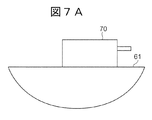
- a lock mechanism 70 for the support member 62 is provided on the upper portion of the main body 61 (FIG. 7A).
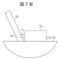
- the protrusion 71 protruding from the lock mechanism 70 is fitted into the recess 63 provided in the support member 62, so that the support member 62 is prevented from moving and the support member 62 maintains the head plate 60 in the open state. (FIG. 7B).
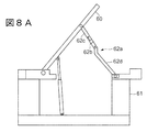
- a support member 62a having a foldable structure is proposed so that the support member 62 does not protrude into the main body 61 when the head plate 60 is closed (FIG. 8A) (see, for example, Patent Document 2). .)
- the support member 62a is divided into an upper member 62c and a lower member 62d with a bending point 62b as a boundary, and a lock mechanism 62e is provided at the bending point 62b.
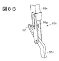
- the lock mechanism 62e includes a hook 62f provided at the upper end of the lower member 62d and a slidable shaft 62g provided at the lower end of the upper member 62c (FIG. 8B).
- the hook 62f is engaged with the shaft 62g. Later, the shaft 62g is slid and pressed against the hook 62f, thereby fixing the hook 62f to the shaft 62g.
- An object of the present invention is to provide a lid member opening / closing mechanism and a substrate inspection apparatus capable of suppressing an increase in cost and opening / closing a lid member without inconvenience.
- a housing-like main body and an openable / closable lid member provided on an upper portion of the main body are accommodated, and the substrate is accommodated in the main body.
- a rod-shaped support member that is interposed between the main body and the lid member when the lid member is in the open state, and has a protrusion on the main body side;
- a guide groove that is provided on the main body and engages with the protrusion, and the protrusion moves along the guide groove, whereby the position of the lid member is adjusted via the support member,
- the guide groove includes a restriction groove for restricting a position of the support member to maintain the lid member in the open state, and a support groove for moving the cover member to the closed state.
- a receiving groove for receiving the The groove branches into the restriction groove and the accommodation groove in the upper part, the restriction groove is shorter than the accommodation groove, the restriction groove exists on the extending direction of the support member in the opened state, and the protrusion And a lid member opening / closing mechanism having an abutting portion that abuts on the surface.
- the guide groove includes the restriction groove for restricting the position of the support member to maintain the lid member in the open state, and the support member to the inside of the main body for shifting the lid member to the closed state.
- the regulating groove has a contact portion that is present on the extending direction of the support member in the opened state and contacts the protruding portion.
- the abutting portion abuts on the protruding portion, and the support member can be prevented from moving through the protruding portion. That is, since it is not necessary to provide a new mechanism for preventing the movement of the support member, an increase in cost can be suppressed.
- the operator can keep the lid member open by simply moving the protruding portion of the support member to the restriction groove, and the operator can move the lid by simply moving the protruding portion of the support member to the receiving groove. Since the member can be shifted to the closed state, the lid member can be opened and closed without inconvenience.
- FIG. 1 is a perspective view schematically illustrating a configuration of a prober as a substrate inspection apparatus to which a lid member opening / closing mechanism according to a first embodiment of the present invention is applied.
- FIG. 2 is a side view schematically showing a configuration of an opening / closing mechanism of the head plate in FIG.
- FIG. 3 is a partially enlarged side view showing the guide plate in FIG.
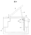
- FIG. 4 is a side view schematically showing a configuration of a lid member opening / closing mechanism according to a second embodiment of the present invention.
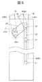
- FIG. 5 is a partially enlarged side view showing the guide plate in FIG.
- FIG. 6 is a perspective view schematically showing a configuration of a lid member opening / closing mechanism in a conventional substrate inspection apparatus.
- FIG. 7B are process diagrams for explaining the operation of the lock mechanism in the conventional lid member opening / closing mechanism.
- FIG. 8A is a side view schematically showing a configuration of a modified example of a conventional lid member opening / closing mechanism.
- 8B is an enlarged partial perspective view showing the configuration of the lock mechanism in the lid member opening / closing mechanism of FIG. 8A.
- FIG. 1 is a perspective view schematically illustrating a configuration of a prober as a substrate inspection apparatus to which a lid member opening / closing mechanism according to the present embodiment is applied.
- a prober 10 includes a main body 12 containing a stage 11 on which a wafer W is placed, a loader 13 disposed adjacent to the main body 12, and a test head 14 disposed so as to cover the main body 12.
- the electrical characteristics of the semiconductor device formed on the wafer W having a large diameter, for example, a diameter of 300 mm or 450 mm, are inspected.
- the main body 12 has a hollow casing shape, and a head plate 15 that exposes the stage 11 by opening the test head 14 when the test head 14 is removed from the main body 12 is provided above the main body 12.
- the head plate 15 is formed of a substantially rectangular flat plate member, and an opening 15a that opens above the wafer W placed on the stage 11 when the head plate 15 is closed is provided at a substantially central portion of the head plate 15.
- a disk-shaped probe card is fitted into the portion 15a via a substantially disk-shaped probe card holder (none of which is shown). As a result, the probe card faces the wafer W. Further, the wafer W is attracted to the stage 11 so that the relative position with respect to the stage 11 does not shift.
- the test head 14 has a rectangular shape and is configured to be rotatable upward by a hinge mechanism 16 provided on the main body 12. When the test head 14 covers the main body 12, the test head 14 is electrically connected to the probe card via a contact ring (not shown). In addition, the test head 14 stores an electrical signal indicating electrical characteristics of the semiconductor device transmitted from the probe card as measurement data and the electrical of the semiconductor device of the wafer W to be inspected based on the measurement data. It has the determination part (all are not shown) which determines the presence or absence of a defect.
- the loader 13 takes out a wafer W on which a semiconductor device is formed, which is housed in a FOUP (not shown), which is a transfer container, and places the wafer W on the stage 11 of the main body 12.
- the finished wafer W is removed from the stage 11 and stored in the FOUP.
- a large number of probe needles are arranged on the surface of the probe card facing the wafer W so as to correspond to the electrode pads and solder bumps of the semiconductor device formed on the wafer W.
- the stage 11 adjusts the relative positions of the probe card and the wafer W to bring the electrode pads of the semiconductor device into contact with the probe needles.
- FIG. 2 is a side view schematically showing the configuration of the opening and closing mechanism of the head plate in FIG.
- a part of the main body 12 is shown in a transparent manner, the head plate 15 in the closed state is shown by a solid line, and the head plate 15 in the opened state is shown by a broken line. It is.
- one end of the head plate 15 is connected to a hinge mechanism 17 provided on the upper portion of the main body 12, and the head plate 15 is opened by rotating around the hinge mechanism 17.
- one end of a rod-shaped rod 18 as a support member is rotated on the lower surface side of the head plate 15. Connected movably.
- the rod 18 is interposed between the head plate 15 and the main body 12, and supports the head plate 15 with respect to the main body 12 so as to maintain the open state of the head plate 15.
- a guide plate 19 is erected along the vertical direction of the main body 12 so as to face the other end of the head plate 15 in the closed state.
- a guide groove 20 is provided in the guide plate 19, and a protruding guide 21 (protrusion) provided at the other end of the rod 18 and protruding to the side of the rod 18 is engaged with the guide groove 20.
- the guide groove 20 is formed along the vertical direction of the main body 12, is formed substantially parallel to the housing groove 22, and is formed substantially parallel to the housing groove 22.
- it has a regulation groove 23 formed in about half of the accommodation groove 22.
- the guide groove 20 has a communication groove 24 that connects the accommodation groove 22 and the regulation groove 23 to each other at the upper part thereof.
- the regulation groove 23 is formed closer to the hinge mechanism 17 than the accommodation groove 22, and the communication groove 24 extends obliquely downward from the upper part of the regulation groove 23 toward the upper part of the accommodation groove 22. That is, the communication groove 24 is inclined so as to descend as it is away from the hinge mechanism 17.
- the rod 18 and the guide groove 20 constitute a lid member opening / closing mechanism.
- FIG. 3 is a partially enlarged side view showing the guide plate in FIG.
- the lower end of the restriction groove 23 is formed in a semicircular shape, and the lower end is in contact with the cylindrical shaft portion 21 a of the guide 21 of the rod 18 in the opened state (hereinafter referred to as “stopper portion”). 23a.
- the stopper portion 23 a supports the head plate 15 via the guide 21 and the rod 18.
- the regulation groove 23 is shorter than the accommodation groove 22 and the stopper portion 23a is located above the lower end of the accommodation groove 22 with respect to the main body 12, the stopper portion 23a maintains the lid open state of the head plate 15 (FIG. (See “State A” in the middle.)
- all the widths of the accommodation groove 22, the regulation groove 23, and the communication groove 24 are set to be larger than the diameter of the shaft 21 a of the guide 21. , And can be moved along the regulation groove 23 and the communication groove 24.
- the operator moves the guide 21 along the communication groove 24 toward the accommodation groove 22.
- the communication groove 24 is formed obliquely downward and is substantially parallel to the extending direction of the rod 18, so that the load from the rod 18 due to the weight of the head plate 15 and the rod 18 is almost equal to that of the communication groove 24. It does not act on the side wall or the like (see “State B” in the figure). As a result, the operator can smoothly move the guide 21 in the communication groove 24.
- the operator pulls the guide 21 into the accommodation groove 22 (see “state C” in the figure), and further lowers the guide 21 to the lower end of the accommodation groove 22.
- the accommodation groove 22 is formed almost to the vicinity of the lower end of the guide plate 19, when the guide 21 is lowered to the lower end of the accommodation groove 22, the entire rod 18 is accommodated inside the main body 12.
- the head plate 15 is shifted to the closed state (see “state D” in the figure).
- the guide groove 20 includes the regulation groove 23 that regulates the position of the rod 18 in order to maintain the head plate 15 in the open state, and the head plate 15 in the closed state.
- the restriction groove 23 exists in the extending direction of the rod 18 in the opened state, and is in contact with the shaft portion 21a of the guide 21. It has a stopper portion 23a in contact therewith. The stopper portion 23 a abuts on the shaft portion 21 a of the guide 21 and can prevent the rod 18 from moving through the guide 21. That is, since it is not necessary to provide a new mechanism for preventing the movement of the rod 18, an increase in cost can be suppressed.
- the operator can maintain the head plate 15 in the open state only by moving the guide 21 of the rod 18 from the receiving groove 22 to the restricting groove 23. Further, the operator can hold the guide 21 of the rod 18 in the restricting groove. Since the head plate 15 can be shifted to the closed state simply by moving from 23 to the accommodation groove 22, the head plate 15 can be opened and closed without any inconvenience.
- This embodiment is basically the same in configuration and operation as the above-described first embodiment, and only the shape of the guide groove 26 in the guide plate 25 is different from the above-described first embodiment. Therefore, the description of the duplicated configuration and operation is omitted, and the description of the different configuration and operation is given below.
- FIG. 4 is a side view schematically showing the configuration of the lid member opening / closing mechanism according to the present embodiment. Also in FIG. 4, in order to explain the lid member opening / closing mechanism, a part of the main body 12 is shown in a transparent manner, the head plate 15 in the closed state is shown by a solid line, and the head plate 15 in the opened state is shown by a broken line. It is.
- a guide groove 26 is provided in a guide plate 25 erected inside the main body 12 like the guide plate 19, and a guide 21 of the rod 18 is engaged with the guide groove 26.
- the guide groove 26 is formed along the vertical direction of the main body 12, and is formed closer to the hinge mechanism 17 than the accommodation groove 27, and the accommodation groove 27 formed almost to the vicinity of the lower end of the guide plate 25.
- a regulating groove 28 directly connected to the accommodation groove 27 at the upper part.
- the restriction groove 28 extends obliquely upward toward the upper part of the accommodation groove 27. That is, the regulation groove 28 is inclined so as to rise as it is separated from the hinge mechanism 17.
- the rod 18 and the guide groove 26 constitute a lid member opening / closing mechanism.
- FIG. 5 is a partially enlarged side view showing the guide plate in FIG.
- the lower end of the regulation groove 28 has a U-shape with rounded corners, and the lower end has a stopper portion 28 a that contacts the shaft portion 21 a of the guide 21 of the rod 18 in the opened state.
- the stopper portion 28a also supports the head plate 15 via the guide 21 and the rod 18, and maintains the open state of the head plate 15 (see “state A” in the figure).
- the upper extension angle of the restriction groove 28 is, for example, such that the extension direction of the rod 18 and the extension direction of the restriction groove 28 form a narrow angle in the open state (see “state A” in the figure).
- the intersection angle is set to be 70 ° or less.
- the widths of both the accommodation groove 27 and the regulation groove 28 are set larger than the diameter of the shaft 21 a of the guide 21, the operator can remove the guide 21 by the relatively light force. Can be moved along.
- the regulation groove 28 is capable of rotating around the one end of the rod 18 by the guide 21 pulled up from the stopper portion 28a inside the regulation groove 28 (the locus is indicated by a one-dot chain line in the figure).
- the width is, for example, twice or more the diameter of the shaft portion 21a of the guide 21.
- the operator When shifting the head plate 15 from the open state to the closed state, the operator pulls up the guide 21 from the stopper portion 28 a of the restriction groove 28 while holding the rod 18, and rotates around the one end of the rod 18. To move the guide 21 to the upper part of the accommodation groove 27 (see “state B” in the figure). As described above, since the regulation groove 28 has a width that allows the guide 21 to rotate around the one end of the rod 18, the operator smoothly moves the guide 21 from the stopper portion 28 a to the upper portion of the accommodation groove 27. Can be made.
- the operator pulls the guide 21 into the accommodation groove 27 (see “state C” in the figure), and further lowers the guide 21 to the lower end of the accommodation groove 27, thereby bringing the rod 18 into the main body 12.
- the head plate 15 is accommodated and the head plate 15 is moved to the closed state (see “state D” in the figure).
- the operator pulls up the guide 21 from the lower end of the receiving groove 27 to the upper portion of the receiving groove 27, and rotates the guide 21 inside the regulating groove 28. Thereafter, the guide 21 is lowered to the stopper portion 28a.
- the regulation groove 28 and the accommodation groove 27 are directly connected to each other at the upper portion thereof, so that the operator can connect the guide 21 of the rod 18 to each of the regulation groove 28 and the accommodation groove 27. Can be easily moved to.
- the extending direction of the rod 18 in the opened state and the extending direction of the restricting groove 28 form a narrow angle, so that the guide 21 of the rod 18 serves as the head plate 15. Further, it is possible to prevent the rod 18 from moving along the restriction groove 28 due to its own weight.
Landscapes
- Physics & Mathematics (AREA)
- General Physics & Mathematics (AREA)
- Engineering & Computer Science (AREA)
- Computer Hardware Design (AREA)
- Microelectronics & Electronic Packaging (AREA)
- General Engineering & Computer Science (AREA)
- Testing Or Measuring Of Semiconductors Or The Like (AREA)
Abstract
コストの上昇を抑制し、煩わしさを伴うことなく蓋部材を開閉可能な蓋部材開閉機構を提供する。プローバ10は、筐体状の本体12の上部に設けられた開閉可能なヘッドプレート15と、本体12及びヘッドプレート15の間に介在し、本体12側の端部にガイド21を有する棒状のロッド18と、本体12に設けられてガイド21と係合するガイド溝20とを備え、ガイド溝20は、ヘッドプレート15を開蓋状態に維持するためにロッド18の位置を規制する規制溝23と、ヘッドプレート15を閉蓋状態に移行させるためにロッド18を本体12の内部へ収容させる収容溝22とを有し、ガイド溝20は上部において規制溝23及び収容溝22に分岐し、規制溝23は、開蓋状態におけるロッド18の延伸方向上に存在し、ガイド21と当接するストッパ部23aを有する。
Description
本発明は、筐体状の本体を有する基板検査装置の蓋部材の状態を開状態及び閉状態のそれぞれに維持する蓋部材開閉機構及び基板検査装置に関する。
基板としての半導体ウエハ(以下、単に「ウエハ」という。)に形成された半導体デバイス、例えば、パワーデバイスやメモリの電気的特性を検査する装置としてプローバが知られている。
プローバは、多数のプローブ針を有する円板状のプローブカードと、ウエハを載置して上下左右に自在に移動するステージと、該ステージを内蔵する筐体状の本体とを備え、該本体の内部においてプローブカードの各プローブ針を半導体デバイスが有する電極パッドや半田バンプに接触させ、各プローブ針から電極パッドや半田バンプへ検査電流を流すことによって半導体デバイスの電気的特性を検査する(例えば、特許文献1参照。)。
ステージは載置するウエハに形成された半導体デバイスの電極パッドや半田バンプへ各プローブ針を正確に正対させるために精密に移動する必要があり、精密な移動を実現するためにステージには定期的なメンテナンスを施す必要がある。
これに対応して、ステージをメンテナンスする際に作業者が容易にステージを取り扱いすることができるように、本体の上部には開閉可能なヘッドプレートが設けられ、ヘッドプレートが開蓋すると本体の内部のステージが暴露される。
通常、ヘッドプレートの一端は本体の上部に設けられたヒンジ機構に接続され、ヘッドプレートはヒンジ機構を中心に回動することによって開蓋するが、開蓋状態を維持するために、図6に示すように、ヘッドプレート60と本体61の間にロッド状の支持部材62を介在させる。
本体61の上部には、支持部材62のロック機構70が設けられ(図7A)、ヘッドプレート60を開蓋してヘッドプレート60と本体61の間にロッド状の支持部材62を介在させる際、ロック機構70から突出した突出部71が支持部材62に設けられた凹部63に嵌合することにより、支持部材62の移動が阻止されて該支持部材62がヘッドプレート60の開蓋状態を維持する(図7B)。
また、ヘッドプレート60を閉蓋する際、支持部材62が本体61の内部へ突出しないように、折り畳み可能な構造を有する支持部材62aが提案されている(図8A)(例えば、特許文献2参照。)。
この支持部材62aは屈曲点62bを境に上部材62c及び下部材62dに分かれ、屈曲点62bにおいてロック機構62eが設けられる。ロック機構62eは、下部材62dの上端に設けられたフック62fと、上部材62cの下端に設けられたスライド可能なシャフト62gとからなり(図8B)、フック62fをシャフト62gに係合させた後にシャフト62gをスライドさせてフック62fへ押圧させることにより、フック62fをシャフト62gへ固定する。
しかしながら、上述した支持部材62,62aのいずれもロック機構70,62eを必要とするため、構造が複雑となり、コストの上昇を招く。また、ヘッドプレート60を開閉する際、作業者は、支持部材62,62aを保持するだけでなく、ロック機構70,62eを操作する必要があるため、ヘッドプレート60の開閉に煩わしさが伴う。
本発明の目的は、コストの上昇を抑制し、煩わしさを伴うことなく蓋部材を開閉可能な蓋部材開閉機構及び基板検査装置を提供することにある。
上記課題を解決するために、本発明によれば、筐体状の本体と、該本体の上部に設けられた開閉可能な蓋部材とを備え、前記本体の内部に基板を収容して該基板の検査を行う基板検査装置における蓋部材開閉機構において、前記蓋部材が開蓋状態になったときに前記本体及び前記蓋部材の間に介在し、本体側に突出部を有する棒状の支持部材と、前記本体に設けられ、前記突出部と係合するガイド溝とを備え、前記突出部が前記ガイド溝に沿って移動することにより、前記支持部材を介して前記蓋部材の位置が調整され、前記ガイド溝は、前記蓋部材を前記開蓋状態に維持するために前記支持部材の位置を規制する規制溝と、前記蓋部材を閉蓋状態に移行させるために前記支持部材を前記本体の内部へ収容させる収容溝とを有し、前記ガイド溝は上部において前記規制溝及び前記収容溝に分岐し、前記規制溝は前記収容溝よりも短く、前記規制溝は、前記開蓋状態における前記支持部材の延伸方向上に存在し、前記突出部と当接する当接部を有する蓋部材開閉機構が提供される。
本発明によれば、ガイド溝は、蓋部材を開蓋状態に維持するために支持部材の位置を規制する規制溝と、蓋部材を閉蓋状態に移行させるために支持部材を本体の内部へ収容させる収容溝とを有し、規制溝は、開蓋状態における支持部材の延伸方向上に存在し、突出部と当接する当接部を有する。当接部は突出部と当接し、当該突出部を介して支持部材の移動を阻止することができる。すなわち、支持部材の移動を阻止するために新たな機構を設ける必要が無いので、コストの上昇を抑制することができる。また、作業者は支持部材の突出部を規制溝へ移動させるだけで蓋部材を開蓋状態に維持することができ、さらに、作業者は支持部材の突出部を収容溝へ移動させるだけで蓋部材を閉蓋状態に移行させることができるので、煩わしさを伴うことなく蓋部材を開閉することができる。
[図1]本発明の第1の実施の形態に係る蓋部材開閉機構が適用される基板検査装置としてのプローバの構成を概略的に説明する斜視図である。
[図2]図1におけるヘッドプレートの開閉機構の構成を概略的に示す側面図である。
[図3]図2におけるガイド板を示す部分拡大側面図である。
[図4]本発明の第2の実施の形態に係る蓋部材開閉機構の構成を概略的に示す側面図である。
[図5]図4におけるガイド板を示す部分拡大側面図である。
[図6]従来の基板検査装置における蓋部材開閉機構の構成を概略的に示す斜視図である。
[図7A乃至図7B]従来の蓋部材開閉機構におけるロック機構の作動を説明するための工程図である。
[図8A]従来の蓋部材開閉機構の変形例の構成を概略的に示す側面図である。
[図8B]図8Aの蓋部材開閉機構におけるロック機構の構成を示す拡大部分斜視図である。
[図2]図1におけるヘッドプレートの開閉機構の構成を概略的に示す側面図である。
[図3]図2におけるガイド板を示す部分拡大側面図である。
[図4]本発明の第2の実施の形態に係る蓋部材開閉機構の構成を概略的に示す側面図である。
[図5]図4におけるガイド板を示す部分拡大側面図である。
[図6]従来の基板検査装置における蓋部材開閉機構の構成を概略的に示す斜視図である。
[図7A乃至図7B]従来の蓋部材開閉機構におけるロック機構の作動を説明するための工程図である。
[図8A]従来の蓋部材開閉機構の変形例の構成を概略的に示す側面図である。
[図8B]図8Aの蓋部材開閉機構におけるロック機構の構成を示す拡大部分斜視図である。
以下、本発明の実施の形態について図面を参照しながら説明する。
まず、本発明の第1の実施の形態に係る蓋部材開閉機構について説明する。
図1は、本実施の形態に係る蓋部材開閉機構が適用される基板検査装置としてのプローバの構成を概略的に説明する斜視図である。
図1において、プローバ10は、ウエハWを載置するステージ11を内蔵する本体12と、該本体12に隣接して配置されるローダ13と、本体12を覆うように配置されるテストヘッド14とを備え、大口径、例えば、直径が300mmや450mmのウエハWに形成された半導体デバイスの電気的特性の検査を行う。
本体12は内部が空洞の筐体形状を呈し、当該本体12の上部には、テストヘッド14を本体12から除去した際に、開蓋することによってステージ11を暴露するヘッドプレート15が設けられる。ヘッドプレート15は略矩形の平板状部材からなり、その略中心部には、ヘッドプレート15の閉蓋時にステージ11に載置されたウエハWの上方で開口する開口部15aが設けられ、該開口部15aには、略円板状のプローブカードホルダを介して円板状のプローブカードが嵌合される(いずれも図示しない)。これにより、プローブカードはウエハWと対向する。また、ウエハWはステージ11に対する相対位置がずれないように該ステージ11へ吸着される。
テストヘッド14は方体形状を呈し、本体12上に設けられたヒンジ機構16によって上方向へ回動可能に構成される。テストヘッド14が本体12を覆う際、該テストヘッド14はコンタクトリング(図示しない)を介してプローブカードと電気的に接続される。また、テストヘッド14はプローブカードから伝送される半導体デバイスの電気的特性を示す電気信号を測定データとして記憶するデータ記憶部や該測定データに基づいて検査対象のウエハWの半導体デバイスの電気的な欠陥の有無を判定する判定部(いずれも図示しない)を有する。
ローダ13は、搬送容器であるFOUP(図示しない)に収容される、半導体デバイスが形成されたウエハWを取り出して本体12のステージ11へ載置し、また、半導体デバイスの電気的特性の検査が終了したウエハWをステージ11から除去してFOUPへ収容する。
プローブカードにおけるウエハWと対向する面にはウエハWに形成された半導体デバイスの電極パッドや半田バンプに対応して多数のプローブ針が配置される。ステージ11はプローブカード及びウエハWの相対位置を調整して半導体デバイスの電極パッド等を各プローブ針へ当接させる。
図2は、図1におけるヘッドプレートの開閉機構の構成を概略的に示す側面図である。図2では、蓋部材開閉機構を説明するために本体12の一部が透過して示され、さらに閉蓋状態のヘッドプレート15が実線で示され、開蓋状態のヘッドプレート15が破線で示される。
図2において、ヘッドプレート15の一端は本体12の上部に設けられたヒンジ機構17に接続され、ヘッドプレート15はヒンジ機構17を中心に回動することによって開蓋する。
また、ヘッドプレート15の一端とは反対側の他端(以下、単に「他端」という。)の近傍において、当該ヘッドプレート15の下面側には支持部材である棒状のロッド18の一端が回動可能に接続される。ヘッドプレート15の開蓋状態において、ロッド18はヘッドプレート15及び本体12の間に介在し、ヘッドプレート15の開蓋状態を維持するように本体12に対してヘッドプレート15を支持する。
本体12の内部には、閉蓋状態のヘッドプレート15の他端に対向するように、ガイド板19が本体12の上下方向に沿って立設される。ガイド板19にはガイド溝20が設けられ、該ガイド溝20には、ロッド18の他端に設けられてロッド18の側方に突出する突起状のガイド21(突出部)が係合する。
ガイド板19において、ガイド溝20は、本体12の上下方向に沿って形成され、ほぼガイド板19の下端近傍まで形成される収容溝22と、収容溝22と略平行に形成され、収容溝22よりも短く、例えば、収容溝22の約1/2程度に形成される規制溝23とを有する。また、ガイド溝20は、収容溝22及び規制溝23をそれぞれの上部において互いに連結させる連絡溝24を有する。
規制溝23は収容溝22よりもヒンジ機構17の近くに形成され、連絡溝24は規制溝23の上部から収容溝22の上部へ向けて斜め下方に延伸する。すなわち、連絡溝24はヒンジ機構17から離れるに従って下降するように傾斜する。
なお、本実施の形態ではロッド18及びガイド溝20が蓋部材開閉機構を構成する。
図3は、図2におけるガイド板を示す部分拡大側面図である。
図3において、規制溝23の下端は半円状に形成され、該下端は開蓋状態におけるロッド18のガイド21の円柱状のシャフト部21aと当接する部位(以下、「ストッパ部」という。)23aを有する。ストッパ部23aはガイド21及びロッド18を介してヘッドプレート15を支持する。ここで、規制溝23は収容溝22よりも短く、ストッパ部23aは本体12に関して収容溝22の下端よりも上方に位置するので、ストッパ部23aはヘッドプレート15の開蓋状態を維持する(図中「状態A」参照。)。
ガイド溝20では、収容溝22、規制溝23及び連絡溝24のいずれの幅もガイド21のシャフト21aの直径より大きく設定されるため、作業者は比較的に軽い力でガイド21を収容溝22、規制溝23及び連絡溝24に沿って移動させることができる。
ヘッドプレート15を開蓋状態から閉蓋状態へ移行させる際、作業者はロッド18を保持しながら、ガイド21を規制溝23のストッパ部23aから離間させ、規制溝23及び連絡溝24の連結部まで引き上げる。
次いで、作業者は、ガイド21を連絡溝24に沿って収容溝22へ向けて移動させる。連絡溝24は、上述したように、斜め下方に形成されてロッド18の延伸方向とほぼ平行であるため、ヘッドプレート15やロッド18の自重に起因するロッド18からの荷重が殆ど連絡溝24の側壁等へ作用しない(図中「状態B」参照。)。これにより、作業者は連絡溝24においてガイド21を円滑に移動させることができる。
次いで、作業者は、ガイド21を収容溝22へ引きこみ(図中「状態C」参照。)、さらに、ガイド21を収容溝22の下端まで下降させる。ここで、上述したように、収容溝22はほぼガイド板19の下端近傍まで形成されるため、ガイド21が収容溝22の下端まで下降すると、ロッド18の全体が本体12の内部に収容されてヘッドプレート15を閉蓋状態へ移行させる(図中「状態D」参照。)。
ヘッドプレート15を閉蓋状態から開蓋状態へ移行させる際、作業者は、ガイド21を収容溝22の下端から連絡溝24を経由して規制溝23の上部まで引き上げ、その後、規制溝23のストッパ部23aまで下降させる。
本実施の形態に係る蓋部材開閉機構によれば、ガイド溝20は、ヘッドプレート15を開蓋状態に維持するためにロッド18の位置を規制する規制溝23と、ヘッドプレート15を閉蓋状態に移行させるためにロッド18を本体12の内部へ収容させる収容溝22とを有し、規制溝23は、開蓋状態におけるロッド18の延伸方向上に存在し、ガイド21のシャフト部21aと当接するストッパ部23aを有する。ストッパ部23aはガイド21のシャフト部21aと当接し、ガイド21を介してロッド18の移動を阻止することができる。すなわち、ロッド18の移動を阻止するために新たな機構を設ける必要が無いので、コストの上昇を抑制することができる。また、作業者はロッド18のガイド21を収容溝22から規制溝23へ移動させるだけでヘッドプレート15を開蓋状態に維持することができ、さらに、作業者はロッド18のガイド21を規制溝23から収容溝22へ移動させるだけでヘッドプレート15を閉蓋状態に移行させることができるので、煩わしさを伴うことなくヘッドプレート15を開閉することができる。
次に、本発明の第2の実施の形態に係る蓋部材開閉機構について説明する。
本実施の形態は、その構成や作用が上述した第1の実施の形態と基本的に同じであり、ガイド板25におけるガイド溝26の形状のみが上述した第1の実施の形態と異なる。したがって、重複した構成、作用については説明を省略し、以下に異なる構成、作用についての説明を行う。
図4は、本実施の形態に係る蓋部材開閉機構の構成を概略的に示す側面図である。図4でも、蓋部材開閉機構を説明するために本体12の一部が透過して示され、さらに閉蓋状態のヘッドプレート15が実線で示され、開蓋状態のヘッドプレート15が破線で示される。
図4において、ガイド板19と同様に本体12の内部に立設されるガイド板25にはガイド溝26が設けられ、該ガイド溝26には、ロッド18のガイド21が係合する。ガイド板25において、ガイド溝26は、本体12の上下方向に沿って形成され、ほぼガイド板25の下端近傍まで形成される収容溝27と、収容溝27よりもヒンジ機構17の近くに形成され、上部において直接収容溝27へ連結する規制溝28とを有する。規制溝28は収容溝27の上部へ向けて斜め上方に延伸する。すなわち、規制溝28はヒンジ機構17から離れるに従って上昇するように傾斜する。
なお、本実施の形態ではロッド18及びガイド溝26が蓋部材開閉機構を構成する。
図5は、図4におけるガイド板を示す部分拡大側面図である。
図5において、規制溝28の下端は角部が円形処理されたコの字形状を呈し、該下端は開蓋状態におけるロッド18のガイド21のシャフト部21aと当接するストッパ部28aを有する。ストッパ部28aも、ストッパ部23aと同様に、ガイド21及びロッド18を介してヘッドプレート15を支持し、ヘッドプレート15の開蓋状態を維持する(図中「状態A」参照。)。
規制溝28の上方延伸角は、開蓋状態(図中「状態A」参照。)において、ロッド18の延伸方向と、規制溝28の延伸方向とは狭角をなすように、例えば、互いの交差角が70°以下になるように設定される。
ガイド溝26では、収容溝27及び規制溝28のいずれの幅もガイド21のシャフト21aの直径より大きく設定されるため、作業者は比較的に軽い力でガイド21を収容溝27及び規制溝28に沿って移動させることができる。特に、規制溝28は、当該規制溝28の内部においてストッパ部28aから引き上げられたガイド21がロッド18の一端を中心とする回動運動(図中一点鎖線でその軌跡が示される。)可能な幅、例えば、ガイド21のシャフト部21aの直径の2倍以上の幅を有する。
ヘッドプレート15を開蓋状態から閉蓋状態へ移行させる際、作業者はロッド18を保持しながら、ガイド21を規制溝28のストッパ部28aから引き上げ、ロッド18の一端を中心とする回動運動によってガイド21を収容溝27の上部まで移動させる(図中「状態B」参照。)。上述したように、規制溝28は、ガイド21がロッド18の一端を中心とする回動運動可能な幅を有するので、作業者はガイド21をストッパ部28aから収容溝27の上部まで円滑に移動させることができる。
次いで、作業者は、ガイド21を収容溝27へ引きこみ(図中「状態C」参照。)、さらに、ガイド21を収容溝27の下端まで下降させることにより、ロッド18を本体12の内部に収容してヘッドプレート15を閉蓋状態へ移行させる(図中「状態D」参照。)。
ヘッドプレート15を閉蓋状態から開蓋状態へ移行させる際、作業者は、ガイド21を収容溝27の下端から収容溝27の上部まで引き上げ、ガイド21を規制溝28の内部において回動運動させ、その後、ガイド21をストッパ部28aまで下降させる。
本実施の形態に係る蓋部材開閉機構によれば、規制溝28及び収容溝27はそれぞれの上部において直接互いに連結するので、作業者はロッド18のガイド21を規制溝28及び収容溝27のそれぞれへ容易に移動させることができる。
また、本実施の形態に係る蓋部材開閉機構によれば、開蓋状態におけるロッド18の延伸方向と、規制溝28の延伸方向とは狭角をなすので、ロッド18のガイド21がヘッドプレート15やロッド18の自重に起因して規制溝28に沿って移動するのを防止することができる。
以上、本発明について、上記実施の形態を用いて説明したが、本発明は上記実施の形態に限定されるものではない。
本出願は、2013年11月21日に出願された日本出願第2013−241047号に基づく優先権を主張するものであり、当該日本出願に記載された全内容を本出願に援用する。
W ウエハ
11 ステージ
12 本体
15 ヘッドプレート
18 ロッド
20,26 ガイド溝
21 ガイド
22,27 収容溝
23,28 規制溝
23a ストッパ部
24 連絡溝
11 ステージ
12 本体
15 ヘッドプレート
18 ロッド
20,26 ガイド溝
21 ガイド
22,27 収容溝
23,28 規制溝
23a ストッパ部
24 連絡溝
Claims (7)
- 筐体状の本体と、該本体の上部に設けられた開閉可能な蓋部材とを備え、前記本体の内部に基板を収容して該基板の検査を行う基板検査装置における蓋部材開閉機構において、
前記蓋部材が開蓋状態になったときに前記本体及び前記蓋部材の間に介在し、本体側の端部に突出部を有する棒状の支持部材と、
前記本体に設けられ、前記突出部と係合するガイド溝とを備え、
前記突出部が前記ガイド溝に沿って移動することにより、前記支持部材を介して前記蓋部材の位置が調整され、
前記ガイド溝は、前記蓋部材を前記開蓋状態に維持するために前記支持部材の位置を規制する規制溝と、前記蓋部材を閉蓋状態に移行させるために前記支持部材を前記本体の内部へ収容させる収容溝とを有し、
前記ガイド溝は上部において前記規制溝及び前記収容溝に分岐し、前記規制溝は前記収容溝よりも短く、
前記規制溝は、前記開蓋状態における前記支持部材の延伸方向上に存在し、前記突出部と当接する当接部を有することを特徴とする蓋部材開閉機構。 - 前記規制溝及び前記収容溝は前記本体の下方へ延伸し、
前記ガイド溝は、前記規制溝及び前記収容溝をそれぞれの上部において互いに連結させる連絡溝を有することを特徴とする請求項1記載の蓋部材開閉機構。 - 前記規制溝及び前記収容溝は前記本体の下方へ延伸し、
前記規制溝及び前記収容溝はそれぞれの上部において直接互いに連結することを特徴とする請求項1記載の蓋部材開閉機構。 - 前記開蓋状態における前記支持部材の延伸方向と、前記規制溝の延伸方向とは狭角をなすことを特徴とする請求項3記載の蓋部材開閉機構。
- 前記規制溝は、前記支持部材が前記蓋部材と連結する部分を中心に回動する際、前記突出部が円弧運動可能な幅を有することを特徴とする請求項3又は4記載の蓋部材開閉機構。
- 前記突出部は円柱状部材からなり、前記規制溝の幅は、前記突出部の直径の2倍以上であることを特徴とする請求項5記載の蓋部材開閉機構。
- 筐体状の本体と、該本体の上部に設けられた開閉可能な蓋部材と、前記蓋部材を開閉させる蓋部材開閉機構とを備え、前記本体の内部に基板を収容して該基板の検査を行う基板検査装置において、
前記蓋部材開閉機構は、前記蓋部材が開蓋状態になったときに前記本体及び前記蓋部材の間に介在し、本体側に突出部を有する棒状の支持部材と、前記本体に設けられ、前記突出部と係合するガイド溝とを有し、
前記突出部が前記ガイド溝に沿って移動することにより、前記支持部材を介して前記蓋部材の位置が調整され、
前記ガイド溝は、前記蓋部材を前記開蓋状態に維持するために前記支持部材の位置を規制する規制溝と、前記蓋部材を閉蓋状態に移行させるために前記支持部材を前記本体の内部へ収容させる収容溝とを有し、
前記ガイド溝は上部において前記規制溝及び前記収容溝に分岐し、前記規制溝は前記収容溝よりも短く、
前記規制溝は、前記開蓋状態における前記支持部材の延伸方向上に存在し、前記突出部と当接する当接部を有することを特徴とする基板検査装置。
Applications Claiming Priority (2)
| Application Number | Priority Date | Filing Date | Title |
|---|---|---|---|
| JP2013-241047 | 2013-11-21 | ||
| JP2013241047A JP6196890B2 (ja) | 2013-11-21 | 2013-11-21 | 蓋部材開閉機構及び基板検査装置 |
Publications (1)
| Publication Number | Publication Date |
|---|---|
| WO2015076185A1 true WO2015076185A1 (ja) | 2015-05-28 |
Family
ID=53179451
Family Applications (1)
| Application Number | Title | Priority Date | Filing Date |
|---|---|---|---|
| PCT/JP2014/080129 Ceased WO2015076185A1 (ja) | 2013-11-21 | 2014-11-07 | 蓋部材開閉機構及び基板検査装置 |
Country Status (3)
| Country | Link |
|---|---|
| JP (1) | JP6196890B2 (ja) |
| TW (1) | TWI637447B (ja) |
| WO (1) | WO2015076185A1 (ja) |
Families Citing this family (2)
| Publication number | Priority date | Publication date | Assignee | Title |
|---|---|---|---|---|
| JP7023097B2 (ja) * | 2016-12-28 | 2022-02-21 | 東京エレクトロン株式会社 | 真空チャンバおよび真空チャンバの扉の施錠方法 |
| CN115561610B (zh) * | 2022-11-14 | 2023-06-23 | 深圳市思瑞精达精密仪器有限公司 | 一种测量仪器 |
Citations (3)
| Publication number | Priority date | Publication date | Assignee | Title |
|---|---|---|---|---|
| JP2007069673A (ja) * | 2005-09-05 | 2007-03-22 | Hitachi Constr Mach Co Ltd | 作業機械 |
| JP2011163821A (ja) * | 2010-02-05 | 2011-08-25 | Tokyo Electron Ltd | ヘッドプレートの開閉軽減機構及び開閉ロック機構 |
| JP2013076260A (ja) * | 2011-09-30 | 2013-04-25 | Kobelco Contstruction Machinery Ltd | 作業機械 |
-
2013
- 2013-11-21 JP JP2013241047A patent/JP6196890B2/ja active Active
-
2014
- 2014-11-07 WO PCT/JP2014/080129 patent/WO2015076185A1/ja not_active Ceased
- 2014-11-11 TW TW103139038A patent/TWI637447B/zh active
Patent Citations (3)
| Publication number | Priority date | Publication date | Assignee | Title |
|---|---|---|---|---|
| JP2007069673A (ja) * | 2005-09-05 | 2007-03-22 | Hitachi Constr Mach Co Ltd | 作業機械 |
| JP2011163821A (ja) * | 2010-02-05 | 2011-08-25 | Tokyo Electron Ltd | ヘッドプレートの開閉軽減機構及び開閉ロック機構 |
| JP2013076260A (ja) * | 2011-09-30 | 2013-04-25 | Kobelco Contstruction Machinery Ltd | 作業機械 |
Also Published As
| Publication number | Publication date |
|---|---|
| TWI637447B (zh) | 2018-10-01 |
| JP2015103560A (ja) | 2015-06-04 |
| TW201533822A (zh) | 2015-09-01 |
| JP6196890B2 (ja) | 2017-09-13 |
Similar Documents
| Publication | Publication Date | Title |
|---|---|---|
| US11061071B2 (en) | Wafer inspection system, wafer inspection apparatus and prober | |
| KR101523105B1 (ko) | 프로브 장치 | |
| US8267633B2 (en) | FOUP opening/closing device and probe apparatus | |
| WO2015015921A1 (ja) | プローバ | |
| TWI580981B (zh) | Probe device and wafer transfer unit | |
| KR101839214B1 (ko) | 프로브 카드 반송 장치, 프로브 카드 반송 방법 및 프로브 장치 | |
| US11244882B2 (en) | Socket for electrical component | |
| TW200935535A (en) | Probe device and probe method | |
| JP6196890B2 (ja) | 蓋部材開閉機構及び基板検査装置 | |
| US9383389B2 (en) | Prober and needle-tip polishing device for probe card | |
| JP6152311B2 (ja) | 測定容器供給装置 | |
| US8726748B2 (en) | Probe apparatus and substrate transfer method | |
| US20210066871A1 (en) | Socket for Electrical Component | |
| JP6373130B2 (ja) | 電気部品用ソケット | |
| KR20160081360A (ko) | 전기적 검사소켓 | |
| JP2017181053A (ja) | 基板検査装置 | |
| JP6062594B1 (ja) | 測定用ソケットおよびコンタクト装置 | |
| JP2014165234A (ja) | プローブ装置及びウエハローダー | |
| KR101532758B1 (ko) | 래치기구 및 이를 포함하는 반도체 패키지 장착용 소켓 | |
| US11467099B2 (en) | Inspection apparatus | |
| JP2009139370A (ja) | テストキャリア及びこれを有するテスト装置ならびに半導体装置のテスト方法 | |
| JP2007227192A (ja) | 試料保持装置および荷電粒子線装置 | |
| JP2017116369A (ja) | 電子部品搬送装置および電子部品検査装置 | |
| JP2014194978A (ja) | プローブカードホルダ及び基板検査装置 | |
| JP2003308939A (ja) | 電気部品用ソケット |
Legal Events
| Date | Code | Title | Description |
|---|---|---|---|
| 121 | Ep: the epo has been informed by wipo that ep was designated in this application |
Ref document number: 14863959 Country of ref document: EP Kind code of ref document: A1 |
|
| DPE1 | Request for preliminary examination filed after expiration of 19th month from priority date (pct application filed from 20040101) | ||
| NENP | Non-entry into the national phase |
Ref country code: DE |
|
| 122 | Ep: pct application non-entry in european phase |
Ref document number: 14863959 Country of ref document: EP Kind code of ref document: A1 |