WO2015075967A1 - 自走式掃除機 - Google Patents
自走式掃除機 Download PDFInfo
- Publication number
- WO2015075967A1 WO2015075967A1 PCT/JP2014/069335 JP2014069335W WO2015075967A1 WO 2015075967 A1 WO2015075967 A1 WO 2015075967A1 JP 2014069335 W JP2014069335 W JP 2014069335W WO 2015075967 A1 WO2015075967 A1 WO 2015075967A1
- Authority
- WO
- WIPO (PCT)
- Prior art keywords
- dust
- self
- port
- dust box
- filter
- Prior art date
- Legal status (The legal status is an assumption and is not a legal conclusion. Google has not performed a legal analysis and makes no representation as to the accuracy of the status listed.)
- Ceased
Links
Images

Classifications
-
- A—HUMAN NECESSITIES
- A47—FURNITURE; DOMESTIC ARTICLES OR APPLIANCES; COFFEE MILLS; SPICE MILLS; SUCTION CLEANERS IN GENERAL
- A47L—DOMESTIC WASHING OR CLEANING; SUCTION CLEANERS IN GENERAL
- A47L5/00—Structural features of suction cleaners
- A47L5/12—Structural features of suction cleaners with power-driven air-pumps or air-compressors, e.g. driven by motor vehicle engine vacuum
- A47L5/22—Structural features of suction cleaners with power-driven air-pumps or air-compressors, e.g. driven by motor vehicle engine vacuum with rotary fans
-
- A—HUMAN NECESSITIES
- A47—FURNITURE; DOMESTIC ARTICLES OR APPLIANCES; COFFEE MILLS; SPICE MILLS; SUCTION CLEANERS IN GENERAL
- A47L—DOMESTIC WASHING OR CLEANING; SUCTION CLEANERS IN GENERAL
- A47L9/00—Details or accessories of suction cleaners, e.g. mechanical means for controlling the suction or for effecting pulsating action; Storing devices specially adapted to suction cleaners or parts thereof; Carrying-vehicles specially adapted for suction cleaners
- A47L9/10—Filters; Dust separators; Dust removal; Automatic exchange of filters
- A47L9/12—Dry filters
- A47L9/122—Dry filters flat
-
- A—HUMAN NECESSITIES
- A47—FURNITURE; DOMESTIC ARTICLES OR APPLIANCES; COFFEE MILLS; SPICE MILLS; SUCTION CLEANERS IN GENERAL
- A47L—DOMESTIC WASHING OR CLEANING; SUCTION CLEANERS IN GENERAL
- A47L9/00—Details or accessories of suction cleaners, e.g. mechanical means for controlling the suction or for effecting pulsating action; Storing devices specially adapted to suction cleaners or parts thereof; Carrying-vehicles specially adapted for suction cleaners
- A47L9/10—Filters; Dust separators; Dust removal; Automatic exchange of filters
- A47L9/14—Bags or the like; Rigid filtering receptacles; Attachment of, or closures for, bags or receptacles
- A47L9/1409—Rigid filtering receptacles
-
- A—HUMAN NECESSITIES
- A47—FURNITURE; DOMESTIC ARTICLES OR APPLIANCES; COFFEE MILLS; SPICE MILLS; SUCTION CLEANERS IN GENERAL
- A47L—DOMESTIC WASHING OR CLEANING; SUCTION CLEANERS IN GENERAL
- A47L9/00—Details or accessories of suction cleaners, e.g. mechanical means for controlling the suction or for effecting pulsating action; Storing devices specially adapted to suction cleaners or parts thereof; Carrying-vehicles specially adapted for suction cleaners
- A47L9/28—Installation of the electric equipment, e.g. adaptation or attachment to the suction cleaner; Controlling suction cleaners by electric means
-
- A—HUMAN NECESSITIES
- A47—FURNITURE; DOMESTIC ARTICLES OR APPLIANCES; COFFEE MILLS; SPICE MILLS; SUCTION CLEANERS IN GENERAL
- A47L—DOMESTIC WASHING OR CLEANING; SUCTION CLEANERS IN GENERAL
- A47L2201/00—Robotic cleaning machines, i.e. with automatic control of the travelling movement or the cleaning operation
Definitions
- the present invention relates to a self-propelled cleaner.
- Patent Document 1 As a self-propelled cleaner for cleaning dust such as a floor surface, Patent Document 1 includes a self-propelled housing having a suction port on a lower surface, a main brush provided rotatably on the suction port, There has been proposed a self-propelled cleaner provided with a side brush provided to be rotatable forward of the main brush on the lower surface of the housing.
- the casing has a built-in rechargeable battery and a drive / stop switch on the top surface.
- a dust collection unit is detachably provided at the rear of the housing.
- the dust collection unit is provided in the ventilation port, a dust case having an inlet, an exhaust port, a partition wall that bisects the space between the inlet side and the exhaust port side, and a ventilation port formed in a part of the partition wall.
- a filter and an electric blower provided in a space on the exhaust port side of the dust case.
- a pair of positive and negative terminals that are electrically connected to the rechargeable battery via lead wires are provided at the rear of the housing, while the dust case of the dust collection unit is electrically connected to the electric blower via lead wires.
- a pair of metal terminals to be connected to is provided. In a state where the dust collection unit is attached to the rear part of the casing, the positive and negative electrode terminals and the pair of metal terminals are electrically connected.
- the dust collection unit When disposing of dust accumulated in the dust collection space of the dust collection unit, remove the dust collection unit from the housing and discharge the internal dust into the trash can with the inlet facing downward. At this time, the dust collection space can be swept using a brush as an accessory.
- This invention is made
- a self-propelled casing having a suction port provided on the lower surface and an exhaust port provided on the left and right sides of the rear part, and a ventilation path between the suction port and the exhaust port.
- a dust collecting part provided via The dust collection unit has a dust box disposed on the suction port side and an electric blower disposed on the exhaust port side, and is configured to be separable from the dust box and the electric blower.
- a vacuum cleaner is provided.
- the self-propelled cleaner of the present invention is configured such that the dust box and the electric blower in the dust collecting part can be separated. Therefore, after removing the dust box from the housing and discarding the dust inside, the dust box can be washed with water and removed without leaving fine dust. That is, the dust box can be sufficiently cleaned.
- the exhaust port is provided on one of the left and right sides of the rear part of the housing, and the electric blower is disposed on the exhaust port side, a dust box is disposed on the opposite side of the electric blower. Therefore, compared with the case where an electric blower is arrange
- Embodiment 1 of the self-propelled cleaner of this invention It is a top view which shows Embodiment 1 of the self-propelled cleaner of this invention. It is a bottom view of the self-propelled cleaner of Embodiment 1. It is a partial cross section top view for demonstrating the internal structure of the dust collecting part in the self-propelled cleaner of FIG. It is a sectional side view which shows the dust collection part in the self-propelled cleaner of Embodiment 1, Comprising: (A) shows a dust box mounting state, (B) shows a dust box detached state. It is a perspective view of the dust box in the self-propelled cleaner of Embodiment 1. It is a rear view in the dust box detached state of the self-propelled cleaner of Embodiment 1.
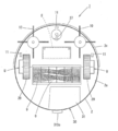
- FIG. 1 is a plan view showing Embodiment 1 of the self-propelled cleaner of the present invention
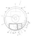
- FIG. 2 is a bottom view of the self-propelled cleaner of Embodiment 1
- FIG. 3 is the self-propelled cleaner of FIG. It is a partial cross section top view for demonstrating the internal structure of the dust collection part in a machine.
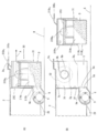
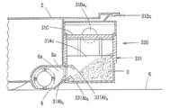
- FIG. 4 is a side sectional view showing a dust collecting portion in the self-propelled cleaner of the first embodiment, where (A) shows a dust box mounted state and (B) shows a dust box detached state.
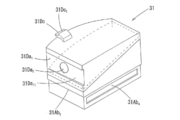
- FIG. 5 is a perspective view of the dust box in the self-propelled cleaner of the first embodiment
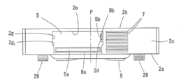
- FIG. 6 is a rear view of the self-propelled cleaner of the first embodiment when the dust box is detached
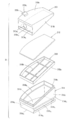
- FIG. 7 is the embodiment. It is an exploded view of the dust box in 1 self-propelled cleaner.
- the self-propelled electronic device sucks air containing dust on the floor surface while self-propelled on the floor surface where it is installed.
- This is a self-propelled cleaner 1 that cleans the floor surface by exhausting the air from which the air is removed.
- the self-propelled cleaner 1 includes a disk-shaped housing 2 that has a suction port 6 on the lower surface and accommodates a battery E that serves as a power source.
- a rotating brush 9 and a side are provided inside and outside the housing 2.
- a component such as a control board S connected to is provided.
- the casing 2 can be supported so that the weight of the self-propelled cleaner 1 can be supported by the pair of driving wheels 29 and the front wheels 27 disposed in the middle in the front-rear direction with respect to the casing 2.
- weight is distributed in the front-rear direction.
- the housing 2 having a central axis P perpendicular to the center is a bottom plate 2a having a substantially circular bottom plate 2a having a suction port 6 formed at a rear position relative to the front and rear middle, and a top plate having a drive / stop button 3 at the central position. 2b, and a side plate 2c having an annular shape in plan view provided along the outer peripheral portions of the bottom plate 2a and the top plate 2b.
- the bottom plate 2a is formed with a plurality of holes for projecting the pair of driving wheels 29 from the inside of the housing 2 to the outside, and an exhaust port 7 is formed on one of the left and right sides of the rear portion of the side plate 2c.
- the exhaust port 7 is arrange
- the side plate 2c is divided into two in the front and rear directions, and the front side portion of the side plate functions as a bumper.
- the suction port 6 is an open surface of a recess formed on the bottom surface of the housing 2 (the lower surface of the bottom plate 2a) so as to face the floor surface K.
- a rotary brush 9 that rotates about an axis parallel to the bottom surface of the housing 2 is provided in the suction port 6, and a side brush 10 that rotates about a vertical rotation axis on the left and right sides of the suction port 6. Is provided.
- the rotating brush 9 is formed by implanting a brush spirally on the outer peripheral surface of a roller that is a rotating shaft.
- the side brush 10 is formed by providing a brush bundle radially at the lower end of the rotating shaft.
- the rotating shaft of the rotating brush 9 and the rotating shaft of the pair of side brushes 10 are pivotally attached to a part of the bottom plate 2a of the housing 2 and include a drive motor, a pulley, a belt, and the like provided in the vicinity thereof. It is connected via a power transmission mechanism.
- the floor surface detection sensor 11 is disposed in front of the front wheel 27 on the bottom surface of the housing 2 and in front of the side portions of the left and right drive wheels 29.
- the detection signal is transmitted to the control unit, and the control unit provided on the control board S controls to stop both driving wheels 29.
- the control board S is provided with a control circuit that controls each element such as the drive wheel 29, the rotating brush 9, the side brush 10, and the electric blower 32 in the self-propelled cleaner 1.
- This self-propelled cleaner 1 turns when the left and right drive wheels 29 rotate forward in the same direction, move forward, move backward in the same direction, move backward, and rotate in opposite directions. For example, when the self-propelled cleaner 1 reaches the periphery of the cleaning area or collides with an obstacle on the course, the driving wheel 29 stops and the left and right driving wheels 29 rotate in opposite directions to each other. change. Thereby, the self-propelled cleaner 1 can be self-propelled while avoiding obstacles in the entire installation place or the entire desired range.
- the dust collection unit 30 is provided between the suction port 6 and the exhaust port 7 of the housing 2 via a ventilation path. 4A and 4B, the illustration of the structure in front of the dust collection unit 30 is omitted.
- This dust collection part 30 has the dust box 31 arrange
- the housing 2 has a rear opening 5 formed so as to be cut out from the upper part to the lower part of the rear part of the side plate 2c.
- the rear opening 5 is an opening for fitting the dust box 31 and is provided at a position shifted from the central axis P to the left or right side.
- the rear opening 5 is provided at a position shifted to the left side from the central axis P when viewed from the rear. Details of the rear opening 5 will be described later.
- the casing 2 includes an upstream ventilation path 6a that communicates the suction port 6 and the rear opening 5, a downstream ventilation path 7a that communicates the exhaust port 7 and the rear opening 5, and an upstream ventilation path 6a.
- the first packing 8a provided around the first connection port 5a on the rear opening 5 side and the second packing provided around the second connection port 5b on the rear opening 5 side in the downstream ventilation path 7a. 8b.
- the 1st packing 8a consists of rubber rings, and the attachment to the circumference
- the second packing 8b is also made of a rubber ring, and is attached to the periphery of the second connection port 5b by, for example, bonding with an adhesive or fitting around the annular convex portion provided around the second connection port 5b. Etc.
- the electric blower 32 is fixed in the downstream side ventilation path 7a disposed beside the rear opening 5 in the housing 2 (right side as viewed from the rear), and the suction port of the electric blower 32 is connected to the second connection. It arrange
- the dust box 31 includes a lower case 31A, a filter case 31B, a filter 31C, and an upper case 31D.
- the filter case 31B that houses the filter 31C is divided into an upper case 31D and a lower case 31A. It is a structure sandwiched between.
- Lower case 31A are upper opening shaped case, and a bottom wall 31Aa having straight sides 31Aa 3 and the arc sides 31Aa 4 connecting the short sides parallel 31Aa 1 and the long 31Aa 2 and their ends, the bottom wall 31Aa And a surrounding wall 31Ab that rises along the outer peripheral edge.
- the upper edge 31Ab 1 of the peripheral wall 31Ab is inclined downwardly from the short sides 31Aa 1 of the bottom wall 31Aa toward the long sides 31Aa 2.
- An inner step 31Ab 2 exposed upward is provided in parallel with the upper end edge 31Ab 1 on the inner peripheral surface of the peripheral wall 31Ab, and an outer step 31Ab 3 (exposed downward on the outer peripheral surface of the peripheral wall 31Ab. 4B), and an inflow port 31Ab 4 that can be connected to the first connection port 5a via the first packing 8a below the outer step portion 31Ab 3 on the front surface side of the surrounding wall 31Ab. Is provided.
- Filter case 31B is drainboard portion 31Bb and the frame portion 31Ba which is supported in the inclined shape in the inner stepped portion 31Ab 2 by being housed in the lower case 31A, which is provided inside the frame portion 31Ba for supporting the filter 31C And have.
- the filter 31C is formed in a size that fits in the frame portion 31Ba of the filter case 31B without a gap.
- a HEPA filter can be used as this filter 31C. Note that the filter 31C may be integrated with the filter case 31B.
- the upper case 31D is a lid that covers the upper opening of the lower case 31A, and includes an upper wall 31Da, a peripheral wall 31Db, and a locking piece 31Dc provided at the rear portion of the upper wall 31Da.
- the upper and lower intermediate positions of the long side corresponding portion in the surrounding wall 31Db are buried so as to incline in the left-right direction from the rear to the front, and the second connection is made to the buried inclined wall portion 31Da 1 via the second packing 8b.
- a discharge port 31Da 2 that can be connected to the port 5b is formed.
- the outer surface of the inclined wall portion 31Da 1 is an opposed inclined side surface portion 31Da 11 that faces an inclined side surface portion 2d described later of the housing 2.
- Engaging piece 31dc is a protruding elastically deformable pieces as bent from the rear of the upper wall 31Da to the rear and cross-sectional shape locking projection 31dc 1 triangle is provided on the upper surface thereof.
- a filter 31C is disposed between the inlet 31Ab 4 and an outlet 31Da 2, the dust collecting chamber 31Ac is formed between the inlet 31Ab 4 and the filter 31C.
- the rear opening 5 is configured as follows.
- the side provided with the electric blower 32 is provided with an inclined side surface portion 2d that is inclined in the left-right direction toward the front.
- the right side wall 2g as viewed from the rear is provided with an inclined side surface portion 2d that is inclined leftward toward the front. Note that the upper and lower sides of the inclined side surface portion 2d on the side wall 2g are vertical surfaces.
- the rear opening 5 has a back wall 2f where the first packing 8a is provided and the left and right side walls 2g on the left and right sides of the back wall 2f.
- the left and right side walls 2g have an outer step portion 31Ab of the dust box 31.
- Left and right step portions 2g 1 for supporting 3 are provided.
- a space for storing the locking piece 31Dc of the dust box 31 is formed at the rear of the ceiling wall 2e of the rear opening 5, and the locking projection 31Dc 1 of the locking piece 31Dc is formed in the ceiling portion of the space. Is provided with a locking recess 2e 1 that is detachably locked.
- the opposing inclined sidewall 31Da 11 of the dust box 31 is brought into close contact with the second packing 8b, the locking projections 31dc 1 by engaging piece 31dc is elastically deformed in the housing 2 ceiling wall 2e Get over the part and lock in the locking recess 2e 1 .
- the dust box 31 is mounted in the rear opening 5 of the housing 2 without dropping off.
- the electric blower 32, the drive wheel 29, the rotating brush 9, and the side brush 10 are driven by a cleaning operation command.
- the housing 2 includes dust on the floor surface K from the suction port 6 while traveling in a predetermined range while the rotary brush 9, the side brush 10, the drive wheel 29, and the front wheel 27 are in contact with the floor surface K. Inhale air.
- the dust on the floor surface K is scraped up by the rotation of the rotating brush 9 and guided to the suction port 6. Further, the dust on the side of the suction port 6 is guided to the suction port 6 by the rotation of the side brush 10.
- the air containing the dust D sucked into the housing 2 from the suction port 6 passes through the upstream ventilation path 6a of the housing 2 and becomes dust in the dust collecting unit 30. It flows into the collection chamber 31Ac.
- the airflow A that has flowed into the dust collection chamber 31Ac passes through the filter 31c and the electric blower 32, and is discharged from the exhaust port 7 to the outside through the downstream ventilation path 7a.
- the dust D contained in the airflow A in the dust collection chamber 31Ac is captured by the filter 31C, the dust D accumulates in the dust collection chamber 31Ac.
- the filter 31C is held in an inclined shape in the dust box 31, and thereby the area of the filter 31C and the volume of the dust collection chamber 31Ac are increased as compared with the case where the filter 31C is held horizontally.
- the distance of the intake path from the suction port 6 to the electric blower 32 can be increased, and thereby uniform from the entire filter 31C in the dust box 31. It is easy to inhale air and filter clogging is less likely to occur.
- the dust box 31 can be washed with water.
- the filter 31C may be cleaned with a brush or further washed with water.
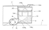
- FIG. 8 is a side cross-sectional view showing a dust collecting part in the self-propelled cleaner of the second embodiment.
- the self-propelled cleaner of the second embodiment is configured in the same manner as in the first embodiment except that the configuration of the dust collecting unit 130 is different from that in the first embodiment.
- Embodiment 2 Embodiment 1 is different from, the dust box 131, suppressing dust outflow inhibition pieces 131ab 5 inlet to spill from the dust D inlet 31Ab 4 of the dust collecting chamber 31Ac of the dust box 131 31Ab 4 It was established in.
- the waste outflow inhibition pieces 131ab 5 projecting obliquely upwardly are provided from the lower edge of the inlet port 31Ab 4 inward.
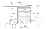
- FIG. 9 is a side cross-sectional view showing a dust collecting portion in the self-propelled cleaner of the third embodiment.
- the self-propelled cleaner of the third embodiment is configured in the same manner as in the first and second embodiments except that the configuration of the dust collecting unit 230 is different from that in the first and second embodiments.
- the dust outflow inhibition pieces 231Ab 5 different is provided in the inlet 31Ab 4 the waste outflow inhibition pieces 131ab 5 embodiment 2.
- the dust outflow inhibition pieces 231Ab 5 projects from the upper edge of the inlet port 31Ab 4 horizontally towards the inside, a piece of inverted L-shaped further sagging downward.
- FIG. 10 is a side cross-sectional view showing a dust collecting part in the self-propelled cleaner of the fourth embodiment.
- the same elements as those in FIG. 8 are denoted by the same reference numerals.
- the self-propelled cleaner according to the fourth embodiment is configured in the same manner as in the first to third embodiments except that the configuration of the dust collecting unit 330 is different from that in the first to third embodiments.
- the dust outflow inhibition pieces 331Ab 5 corresponding to the waste outflow inhibition pieces 131ab 5 embodiment 2 is provided on the lower edge of the inlet port 31Ab 4, it corresponds to waste outflow inhibition pieces 231Ab 5 embodiment 3 waste outflow inhibition pieces 331Ab 6 to is provided at the upper end edge of the inlet port 31Ab 4.
- the fourth embodiment can suppress spillage of dust D from the inlet 31Ab 4 when the dust box 331 is removed from the housing 2.
- the self-propelled cleaner of the present invention includes a suction port provided on the lower surface and a self-propellable housing having an exhaust port provided on one of the left and right sides of the rear part, and between the suction port and the exhaust port.
- a dust collecting part provided through a ventilation path,
- the dust collection unit includes a dust box disposed on the suction port side and an electric blower disposed on the exhaust port side, and the dust box and the electric blower are configured to be separable.
- the self-propelled cleaner of the present invention may be configured as follows.
- the electric blower may be disposed in the casing, and the dust box may be detachably disposed in a rear portion of the casing.
- the center of gravity can be disposed at the front of the housing.
- the housing can be supported by the pair of left and right drive wheels and the front wheels, and the rear wheels can be omitted.
- the casing includes a rear opening portion into which the dust box is fitted, an upstream ventilation path that communicates the suction port and the rear opening portion, and a downstream side that communicates the exhaust port and the rear opening portion.
- a second packing provided, The electric blower is disposed in the downstream ventilation path,
- the dust box includes an inflow port connectable to the first connection port via the first packing, an exhaust port connectable to the second connection port via the second packing, the inflow port and the exhaust port.
- a filter provided between the outlet and a dust collection chamber provided between the inlet and the filter;
- the filter is held in an inclined manner in the dust box so that the end on the discharge port side of the filter is lower than the discharge port and the end opposite to the discharge port is higher than the discharge port. You may make it do. In this way, the area of the filter and the volume of the dust collection chamber can be increased. As a result, it is further advantageous for suppressing clogging of the filter and reducing the load of the electric blower.
- the housing has an inclined side surface portion that inclines in the left-right direction toward the front at a location where the second packing is provided
- the dust box may have an opposing inclined side surface portion that inclines in the left-right direction toward the front at a location where the discharge port is provided. If it does in this way, the circumference
- wearing wearing.
- by providing an inclined side surface portion on the housing side and an opposing inclined side surface portion on the dust box side the problem that the other portion of the dust box is rubbed against the second packing and the second packing wears or falls off is avoided. can do.
- the dust box may be provided with a dust fall prevention piece at the inlet for suppressing spillage of dust in the dust box from the inlet.
- the dust fall prevention piece makes it difficult for dust in the dust box to spill from the inlet to the floor surface and suppresses mistakes that stain the cleaned floor surface. can do.
Landscapes
- Engineering & Computer Science (AREA)
- Mechanical Engineering (AREA)
- Electric Vacuum Cleaner (AREA)
- Electric Suction Cleaners (AREA)
- Filters For Electric Vacuum Cleaners (AREA)
Abstract
Description
前記集塵部は、前記吸込口側に配置されたダストボックスと、前記排気口側に配置された電動送風機とを有し、前記ダストボックスと前記電動送風機とが分離可能に構成されている自走式掃除機が提供される。
<自走式掃除機の全体構成>
図1は本発明の自走式掃除機の実施形態1を示す平面図であり、図2は実施形態1の自走式掃除機の底面図であり、図3は図1の自走式掃除機における集塵部の内部構造を説明するための一部断面平面図である。また、図4は実施形態1の自走式掃除機における集塵部を示す側断面図であって、(A)はダストボックス装着状態を示し、(B)はダストボックス離脱状態を示す。また、図5は実施形態1の自走式掃除機におけるダストボックスの斜視図であり、図6は実施形態1の自走式掃除機のダストボックス離脱状態での背面図であり、図7は実施形態1の自走式掃除機におけるダストボックスの分解図である。
制御基板Sには、自走式掃除機1における駆動輪29、回転ブラシ9、サイドブラシ10、電動送風機32等の各要素を制御する制御回路が設けられている。
図3および図4(A)に示すように、集塵部30は、筐体2の吸込口6と排気口7との間に通風経路を介して設けられている。なお、図4(A)および(B)において、集塵部30より前方の構造は図示を省略している。
第2パッキン8bもゴムリングからなり、その第2接続口5bの周囲への取り付けも、例えば、接着剤による接着、あるいは、第2接続口5bの周囲に設けた環状凸部の周囲に嵌め込む等により行われる。
フィルタ31Cは、フィルタケース31Bの枠部31Ba内に隙間無く収まるサイズに形成されている。このフィルタ31Cとしては、例えば、HEPAフィルタを用いることができる。なお、フィルタ31Cはフィルタケース31Bと一体化されてもよい。
周囲壁31Dbにおける長辺対応部分の上下中間位置は、後方から前方に向かって左右方向へ傾斜するよう埋没しており、その埋没した傾斜壁部31Da1に第2パッキン8bを介して第2接続口5bと接続可能な排出口31Da2が形成されている。なお、傾斜壁部31Da1の外面は、筐体2の後述する傾斜側面部2dと対向する対向傾斜側面部31Da11である。
このように構成されたダストボックス31において、流入口31Ab4と排出口31Da2との間にフィルタ31Cが配置され、流入口31Ab4とフィルタ31Cとの間にダスト捕集室31Acが形成される。
後方開口部5の左右側壁2gのうち電動送風機32が設けられた方には、前方へ向かうにつれて左右方向へ傾斜する傾斜側面部2dが設けられている。実施形態1の場合、後方から視て右側の側壁2gに、前方へ向かうにつれて左方向へ傾斜する傾斜側面部2dが設けられている。なお、側壁2gにおける傾斜側面部2dの上下両側は垂直面となっている。
図8は実施形態2の自走式掃除機における集塵部を示す側断面図である。なお、図8において、図1~図7中の要素と同様の要素には同一の符号を付している。
実施形態2の自走式掃除機はその集塵部130の構成が実施形態1とは異なる以外、実施形態1と同様に構成されている。
図9は実施形態3の自走式掃除機における集塵部を示す側断面図である。なお、図9において、図8中の要素と同様の要素には同一の符号を付している。
実施形態3の自走式掃除機はその集塵部230の構成が実施形態1および2とは異なる以外、実施形態1および2と同様に構成されている。
図10は実施形態4の自走式掃除機における集塵部を示す側断面図である。なお、図10において、図8中の要素と同様の要素には同一の符号を付している。
実施形態4の自走式掃除機はその集塵部330の構成が実施形態1~3とは異なる以外、実施形態1~3と同様に構成されている。
実施形態4も、実施形態2および3と同様に、ダストボックス331を筐体2から取り外す際のダストDの流入口31Ab4からのこぼれ落ちを抑制することができる。
本発明の自走式掃除機において、実施形態1で説明した回転ブラシ9およびサイドブラシ10は必須構成要件ではないため、これらは省略されてもよい。
本発明の自走式掃除機は、下面に設けられた吸込口および後部の左右一方側に設けられた排気口を有する自走可能な筐体と、前記吸込口と前記排気口との間に通風経路を介して設けられた集塵部とを備え、
前記集塵部は、前記吸込口側に配置されたダストボックスと、前記排気口側に配置された電動送風機とを有し、前記ダストボックスと前記電動送風機とが分離可能に構成されている。
(1)前記集塵部において、前記電動送風機は前記筐体内に配置され、前記ダストボックスは前記筐体の後部に着脱可能に配置されてもよい。
このようにすれば、筐体の前部に重量物である電池を配置することができるため、筐体の前部に重心を配置することができる。この結果、左右一対の駆動輪と前輪とで筐体を支持し、後輪を省略することができる。
前記電動送風機は、前記下流側通風経路内に配置され、
前記ダストボックスは、前記第1パッキンを介して前記第1接続口と接続可能な流入口と、前記第2パッキンを介して前記第2接続口と接続可能な排出口と、前記流入口と前記排出口との間に設けられたフィルタと、前記流入口と前記フィルタとの間に設けられたダスト捕集室とを有し、
前記フィルタにおける前記排出口側の端部が前記排出口よりも低くかつ前記排出口側と反対側の端部が前記排出口よりも高くなるように、前記ダストボックス内で前記フィルタを傾斜状に保持するようにしてもよい。
このようにすれば、フィルタの面積およびダスト捕集室の容積を増加させることができる。この結果、フィルタの目詰まりの抑制および電動送風機の負荷低減にさらに有利となる。
前記ダストボックスは、前記排出口が設けられる箇所に、前方へ向かうにつれて左右方向へ傾斜する対向傾斜側面部を有してもよい。
このようにすれば、ダストボックス装着時に、ダストボックスの対向傾斜側面部における排出口の周囲を第2パッキンに容易に密着させることができる。この際、筐体側に傾斜側面部を設け、ダストボックス側に対向傾斜側面部を設けたことにより、ダストボックスの他の箇所が第2パッキンに擦れて第2パッキンが摩耗したり脱落するという不具合を回避することができる。
このようにすれば、床面上でダストボックスを筐体から取り外す際、ダスト落下阻止片によってダストボックス内のダストが流入口から床面上にこぼれ落ち難くなり、清掃した床面を汚してしまうミスを抑制することができる。
2d 傾斜側面部
5 後方開口部
5a 第1接続口
5b 第2接続口
6 吸込口
6a 上流側通風経路
7 排気口
7a 下流側通風経路
8a 第1パッキン
8b 第2パッキン
30、130、230、330 集塵部
31、131、231、331 ダストボックス
31Ab4 流入口
31Ac ダスト捕集室
31C フィルタ
31Da11 対向傾斜側面部
31Da2 排出口
32 電動送風機
131Ab5、231Ab5、331Ab5、331Ab6 ダスト落下阻止片
Claims (5)
- 下面に設けられた吸込口および後部の左右一方側に設けられた排気口を有する自走可能な筐体と、前記吸込口と前記排気口との間に通風経路を介して設けられた集塵部とを備え、
前記集塵部は、前記吸込口側に配置されたダストボックスと、前記排気口側に配置された電動送風機とを有し、前記ダストボックスと前記電動送風機とが分離可能に構成されていることを特徴とする自走式掃除機。 - 前記集塵部において、前記電動送風機は前記筐体内に配置され、前記ダストボックスは前記筐体の後部に着脱可能に配置されている請求項1に記載の自走式掃除機。
- 前記筐体は、前記ダストボックスを嵌め込む後方開口部と、前記吸込口と前記後方開口部とを連通する上流側通風経路と、前記排気口と前記後方開口部とを連通する下流側通風経路と、前記上流側通風経路における前記後方開口部側の第1接続口の周囲に設けられた第1パッキンと、前記下流側通風経路における前記後方開口部側の第2接続口の周囲に設けられた第2パッキンとを有し、
前記電動送風機は、前記下流側通風経路内に配置され、
前記ダストボックスは、前記第1パッキンを介して前記第1接続口と接続可能な流入口と、前記第2パッキンを介して前記第2接続口と接続可能な排出口と、前記流入口と前記排出口との間に設けられたフィルタと、前記流入口と前記フィルタとの間に設けられたダスト捕集室とを有し、
前記フィルタにおける前記排出口側の端部が前記排出口よりも低くかつ前記排出口側と反対側の端部が前記排出口よりも高くなるように、前記ダストボックス内で前記フィルタを傾斜状に保持する請求項2に記載の自走式掃除機。 - 前記筐体は、前記第2パッキンが設けられる箇所に、前方へ向かうにつれて左右方向へ傾斜する傾斜側面部を有し、
前記ダストボックスは、前記排出口が設けられる箇所に、前方へ向かうにつれて左右方向へ傾斜する対向傾斜側面部を有する請求項3に記載の自走式掃除機。 - 前記ダストボックスは、前記ダストボックス内のダストの前記流入口からのこぼれ落ちを抑制するダスト落下阻止片が前記流入口に設けられた請求項3または4に記載の自走式掃除機。
Priority Applications (2)
| Application Number | Priority Date | Filing Date | Title |
|---|---|---|---|
| US14/916,005 US9687127B2 (en) | 2013-11-25 | 2014-07-22 | Self-propelled vacuum cleaner |
| CN201480047479.2A CN105491930B (zh) | 2013-11-25 | 2014-07-22 | 自走式吸尘器 |
Applications Claiming Priority (2)
| Application Number | Priority Date | Filing Date | Title |
|---|---|---|---|
| JP2013242950A JP6289054B2 (ja) | 2013-11-25 | 2013-11-25 | 自走式掃除機 |
| JP2013-242950 | 2013-11-25 |
Publications (1)
| Publication Number | Publication Date |
|---|---|
| WO2015075967A1 true WO2015075967A1 (ja) | 2015-05-28 |
Family
ID=53179246
Family Applications (1)
| Application Number | Title | Priority Date | Filing Date |
|---|---|---|---|
| PCT/JP2014/069335 Ceased WO2015075967A1 (ja) | 2013-11-25 | 2014-07-22 | 自走式掃除機 |
Country Status (4)
| Country | Link |
|---|---|
| US (1) | US9687127B2 (ja) |
| JP (1) | JP6289054B2 (ja) |
| CN (1) | CN105491930B (ja) |
| WO (1) | WO2015075967A1 (ja) |
Families Citing this family (14)
| Publication number | Priority date | Publication date | Assignee | Title |
|---|---|---|---|---|
| JP6349072B2 (ja) * | 2013-11-11 | 2018-06-27 | シャープ株式会社 | 自走式掃除機 |
| JP6496612B2 (ja) * | 2015-06-05 | 2019-04-03 | 株式会社マキタ | 自走式集塵ロボット |
| EP3459419B1 (en) | 2016-05-20 | 2022-10-26 | LG Electronics Inc. | Robot cleaner |
| WO2017200350A1 (ko) | 2016-05-20 | 2017-11-23 | 엘지전자 주식회사 | 로봇 청소기 |
| JP7063534B2 (ja) * | 2016-10-13 | 2022-05-09 | 日立グローバルライフソリューションズ株式会社 | 自走式電気掃除機 |
| JP1594316S (ja) | 2017-04-11 | 2018-01-09 | ||
| JP1594314S (ja) | 2017-04-11 | 2018-01-09 | ||
| US12426753B2 (en) * | 2017-11-16 | 2025-09-30 | Irobot Corporation | Washable bin for a robot vacuum cleaner |
| CN208659188U (zh) * | 2018-03-30 | 2019-03-29 | 江苏美的清洁电器股份有限公司 | 集尘盒及扫地机器人 |
| CN108433633A (zh) * | 2018-06-13 | 2018-08-24 | 山西嘉世达机器人技术有限公司 | 垃圾盒及具有其的清洁机器人 |
| CN214631951U (zh) * | 2019-08-28 | 2021-11-09 | 尚科宁家运营有限公司 | 用于机器人清洁器集尘杯的碎屑鳍片及集尘杯 |
| CN110801177A (zh) * | 2019-11-21 | 2020-02-18 | 苏州高之仙自动化科技有限公司 | 集尘箱和具有其的清洁机器人 |
| JP2021112415A (ja) * | 2020-01-20 | 2021-08-05 | パナソニックIpマネジメント株式会社 | 自律走行型掃除機 |
| TWD222441S (zh) * | 2022-01-05 | 2022-12-01 | 大陸商北京石頭世紀科技股份有限公司 | 塵盒 |
Citations (7)
| Publication number | Priority date | Publication date | Assignee | Title |
|---|---|---|---|---|
| JP2001258807A (ja) * | 2000-03-16 | 2001-09-25 | Sharp Corp | 自走式電気掃除機 |
| JP2005040597A (ja) * | 2003-07-24 | 2005-02-17 | Samsung Kwangju Electronics Co Ltd | ロボット掃除機のホコリ収去筒及びこれを使用して集塵されたホコリを処理する方法 |
| JP2006149528A (ja) * | 2004-11-26 | 2006-06-15 | Toshiba Tec Corp | 電気掃除機 |
| JP2008136670A (ja) * | 2006-12-01 | 2008-06-19 | Toshiba Corp | 電気掃除機 |
| US20090100630A1 (en) * | 2007-10-17 | 2009-04-23 | Samsung Electronics Co., Ltd. | Robot cleaner |
| US20120084934A1 (en) * | 2010-10-11 | 2012-04-12 | Gary Li | Dust collector for mobile robotic vacuum cleaner |
| JP2013526929A (ja) * | 2011-04-08 | 2013-06-27 | モニュエル インコーポレーテッド | ロボット掃除機 |
Family Cites Families (2)
| Publication number | Priority date | Publication date | Assignee | Title |
|---|---|---|---|---|
| ES2706729T3 (es) * | 2005-12-02 | 2019-04-01 | Irobot Corp | Sistema de robot |
| KR101667716B1 (ko) * | 2010-04-01 | 2016-10-19 | 엘지전자 주식회사 | 로봇청소기 |
-
2013
- 2013-11-25 JP JP2013242950A patent/JP6289054B2/ja active Active
-
2014
- 2014-07-22 WO PCT/JP2014/069335 patent/WO2015075967A1/ja not_active Ceased
- 2014-07-22 US US14/916,005 patent/US9687127B2/en not_active Expired - Fee Related
- 2014-07-22 CN CN201480047479.2A patent/CN105491930B/zh not_active Expired - Fee Related
Patent Citations (7)
| Publication number | Priority date | Publication date | Assignee | Title |
|---|---|---|---|---|
| JP2001258807A (ja) * | 2000-03-16 | 2001-09-25 | Sharp Corp | 自走式電気掃除機 |
| JP2005040597A (ja) * | 2003-07-24 | 2005-02-17 | Samsung Kwangju Electronics Co Ltd | ロボット掃除機のホコリ収去筒及びこれを使用して集塵されたホコリを処理する方法 |
| JP2006149528A (ja) * | 2004-11-26 | 2006-06-15 | Toshiba Tec Corp | 電気掃除機 |
| JP2008136670A (ja) * | 2006-12-01 | 2008-06-19 | Toshiba Corp | 電気掃除機 |
| US20090100630A1 (en) * | 2007-10-17 | 2009-04-23 | Samsung Electronics Co., Ltd. | Robot cleaner |
| US20120084934A1 (en) * | 2010-10-11 | 2012-04-12 | Gary Li | Dust collector for mobile robotic vacuum cleaner |
| JP2013526929A (ja) * | 2011-04-08 | 2013-06-27 | モニュエル インコーポレーテッド | ロボット掃除機 |
Also Published As
| Publication number | Publication date |
|---|---|
| US20160198913A1 (en) | 2016-07-14 |
| US9687127B2 (en) | 2017-06-27 |
| JP6289054B2 (ja) | 2018-03-07 |
| JP2015100513A (ja) | 2015-06-04 |
| CN105491930B (zh) | 2017-08-15 |
| CN105491930A (zh) | 2016-04-13 |
Similar Documents
| Publication | Publication Date | Title |
|---|---|---|
| JP6289054B2 (ja) | 自走式掃除機 | |
| JP6349072B2 (ja) | 自走式掃除機 | |
| KR102730954B1 (ko) | 로봇 청소기, 스테이션 및 청소 시스템 | |
| KR102656583B1 (ko) | 로봇 청소기 | |
| CN113226142B (zh) | 机器人清洁器、站和清洁系统 | |
| KR102455228B1 (ko) | 로봇 청소기 | |
| JP6522905B2 (ja) | 電気掃除機 | |
| CN102014720B (zh) | 电动吸尘器 | |
| KR20180038514A (ko) | 전기 청소 장치 | |
| CN106175587B (zh) | 机器人吸尘器 | |
| JP6548875B2 (ja) | 塵埃集塵部および電気掃除機 | |
| TWI871985B (zh) | 集塵樁、清潔機器人及其相關的清潔系統 | |
| US20160081523A1 (en) | Robot cleaner | |
| WO2013179715A1 (ja) | 充電式電気掃除機 | |
| CA2753065A1 (en) | Vacuum cleaner with recirculated cooling air | |
| JP2015112204A (ja) | 電気掃除機 | |
| CN221903499U (zh) | 集尘盒、清洁装置及清洁系统 | |
| JP4738064B2 (ja) | 電気掃除機 | |
| JP2013017499A (ja) | 室内用集塵装置およびこの装置を機能させるためのプログラム | |
| CN211299803U (zh) | 尘杯和具有它的吸尘器 | |
| KR101012943B1 (ko) | 실내 구석 청소가 가능한 흡입 장치 | |
| TW201212869A (en) | Dust collecting apparatus and electric suction cleaner | |
| JP6313142B2 (ja) | 電気掃除機 | |
| CN216147985U (zh) | 尘桶、集尘站及扫地机器人系统 | |
| CN120391928A (zh) | 集尘盒、清洁装置及清洁系统 |
Legal Events
| Date | Code | Title | Description |
|---|---|---|---|
| WWE | Wipo information: entry into national phase |
Ref document number: 201480047479.2 Country of ref document: CN |
|
| 121 | Ep: the epo has been informed by wipo that ep was designated in this application |
Ref document number: 14864346 Country of ref document: EP Kind code of ref document: A1 |
|
| WWE | Wipo information: entry into national phase |
Ref document number: 14916005 Country of ref document: US |
|
| NENP | Non-entry into the national phase |
Ref country code: DE |
|
| 122 | Ep: pct application non-entry in european phase |
Ref document number: 14864346 Country of ref document: EP Kind code of ref document: A1 |