WO2015075866A1 - ロータリースクリーン版及び二次電池の製造方法 - Google Patents
ロータリースクリーン版及び二次電池の製造方法 Download PDFInfo
- Publication number
- WO2015075866A1 WO2015075866A1 PCT/JP2014/005352 JP2014005352W WO2015075866A1 WO 2015075866 A1 WO2015075866 A1 WO 2015075866A1 JP 2014005352 W JP2014005352 W JP 2014005352W WO 2015075866 A1 WO2015075866 A1 WO 2015075866A1
- Authority
- WO
- WIPO (PCT)
- Prior art keywords
- rotary screen
- screen plate
- electrode mixture
- current collector
- mixture paste
- Prior art date
- Legal status (The legal status is an assumption and is not a legal conclusion. Google has not performed a legal analysis and makes no representation as to the accuracy of the status listed.)
- Ceased
Links
Images




Classifications
-
- B—PERFORMING OPERATIONS; TRANSPORTING
- B41—PRINTING; LINING MACHINES; TYPEWRITERS; STAMPS
- B41F—PRINTING MACHINES OR PRESSES
- B41F15/00—Screen printers
- B41F15/14—Details
- B41F15/34—Screens, Frames; Holders therefor
- B41F15/38—Screens, Frames; Holders therefor curved
-
- B—PERFORMING OPERATIONS; TRANSPORTING
- B41—PRINTING; LINING MACHINES; TYPEWRITERS; STAMPS
- B41N—PRINTING PLATES OR FOILS; MATERIALS FOR SURFACES USED IN PRINTING MACHINES FOR PRINTING, INKING, DAMPING, OR THE LIKE; PREPARING SUCH SURFACES FOR USE AND CONSERVING THEM
- B41N1/00—Printing plates or foils; Materials therefor
- B41N1/24—Stencils; Stencil materials; Carriers therefor
-
- H—ELECTRICITY
- H01—ELECTRIC ELEMENTS
- H01M—PROCESSES OR MEANS, e.g. BATTERIES, FOR THE DIRECT CONVERSION OF CHEMICAL ENERGY INTO ELECTRICAL ENERGY
- H01M4/00—Electrodes
- H01M4/02—Electrodes composed of, or comprising, active material
- H01M4/04—Processes of manufacture in general
-
- H—ELECTRICITY
- H01—ELECTRIC ELEMENTS
- H01M—PROCESSES OR MEANS, e.g. BATTERIES, FOR THE DIRECT CONVERSION OF CHEMICAL ENERGY INTO ELECTRICAL ENERGY
- H01M4/00—Electrodes
- H01M4/02—Electrodes composed of, or comprising, active material
- H01M4/04—Processes of manufacture in general
- H01M4/0402—Methods of deposition of the material
- H01M4/0404—Methods of deposition of the material by coating on electrode collectors
-
- H—ELECTRICITY
- H01—ELECTRIC ELEMENTS
- H01M—PROCESSES OR MEANS, e.g. BATTERIES, FOR THE DIRECT CONVERSION OF CHEMICAL ENERGY INTO ELECTRICAL ENERGY
- H01M4/00—Electrodes
- H01M4/02—Electrodes composed of, or comprising, active material
- H01M4/04—Processes of manufacture in general
- H01M4/0402—Methods of deposition of the material
- H01M4/0414—Methods of deposition of the material by screen printing
-
- H—ELECTRICITY
- H01—ELECTRIC ELEMENTS
- H01M—PROCESSES OR MEANS, e.g. BATTERIES, FOR THE DIRECT CONVERSION OF CHEMICAL ENERGY INTO ELECTRICAL ENERGY
- H01M4/00—Electrodes
- H01M4/02—Electrodes composed of, or comprising, active material
- H01M4/13—Electrodes for accumulators with non-aqueous electrolyte, e.g. for lithium-accumulators; Processes of manufacture thereof
- H01M4/131—Electrodes based on mixed oxides or hydroxides, or on mixtures of oxides or hydroxides, e.g. LiCoOx
-
- H—ELECTRICITY
- H01—ELECTRIC ELEMENTS
- H01M—PROCESSES OR MEANS, e.g. BATTERIES, FOR THE DIRECT CONVERSION OF CHEMICAL ENERGY INTO ELECTRICAL ENERGY
- H01M4/00—Electrodes
- H01M4/02—Electrodes composed of, or comprising, active material
- H01M4/13—Electrodes for accumulators with non-aqueous electrolyte, e.g. for lithium-accumulators; Processes of manufacture thereof
- H01M4/139—Processes of manufacture
- H01M4/1391—Processes of manufacture of electrodes based on mixed oxides or hydroxides, or on mixtures of oxides or hydroxides, e.g. LiCoOx
-
- H—ELECTRICITY
- H01—ELECTRIC ELEMENTS
- H01M—PROCESSES OR MEANS, e.g. BATTERIES, FOR THE DIRECT CONVERSION OF CHEMICAL ENERGY INTO ELECTRICAL ENERGY
- H01M4/00—Electrodes
- H01M4/02—Electrodes composed of, or comprising, active material
- H01M4/36—Selection of substances as active materials, active masses, active liquids
- H01M4/48—Selection of substances as active materials, active masses, active liquids of inorganic oxides or hydroxides
- H01M4/50—Selection of substances as active materials, active masses, active liquids of inorganic oxides or hydroxides of manganese
- H01M4/505—Selection of substances as active materials, active masses, active liquids of inorganic oxides or hydroxides of manganese of mixed oxides or hydroxides containing manganese for inserting or intercalating light metals, e.g. LiMn2O4 or LiMn2OxFy
-
- H—ELECTRICITY
- H01—ELECTRIC ELEMENTS
- H01M—PROCESSES OR MEANS, e.g. BATTERIES, FOR THE DIRECT CONVERSION OF CHEMICAL ENERGY INTO ELECTRICAL ENERGY
- H01M4/00—Electrodes
- H01M4/02—Electrodes composed of, or comprising, active material
- H01M4/36—Selection of substances as active materials, active masses, active liquids
- H01M4/48—Selection of substances as active materials, active masses, active liquids of inorganic oxides or hydroxides
- H01M4/52—Selection of substances as active materials, active masses, active liquids of inorganic oxides or hydroxides of nickel, cobalt or iron
- H01M4/525—Selection of substances as active materials, active masses, active liquids of inorganic oxides or hydroxides of nickel, cobalt or iron of mixed oxides or hydroxides containing iron, cobalt or nickel for inserting or intercalating light metals, e.g. LiNiO2, LiCoO2 or LiCoOxFy
-
- H—ELECTRICITY
- H01—ELECTRIC ELEMENTS
- H01M—PROCESSES OR MEANS, e.g. BATTERIES, FOR THE DIRECT CONVERSION OF CHEMICAL ENERGY INTO ELECTRICAL ENERGY
- H01M4/00—Electrodes
- H01M4/02—Electrodes composed of, or comprising, active material
- H01M4/62—Selection of inactive substances as ingredients for active masses, e.g. binders, fillers
- H01M4/621—Binders
- H01M4/622—Binders being polymers
- H01M4/623—Binders being polymers fluorinated polymers
-
- H—ELECTRICITY
- H01—ELECTRIC ELEMENTS
- H01M—PROCESSES OR MEANS, e.g. BATTERIES, FOR THE DIRECT CONVERSION OF CHEMICAL ENERGY INTO ELECTRICAL ENERGY
- H01M4/00—Electrodes
- H01M4/02—Electrodes composed of, or comprising, active material
- H01M4/62—Selection of inactive substances as ingredients for active masses, e.g. binders, fillers
- H01M4/624—Electric conductive fillers
- H01M4/625—Carbon or graphite
-
- B—PERFORMING OPERATIONS; TRANSPORTING
- B41—PRINTING; LINING MACHINES; TYPEWRITERS; STAMPS
- B41C—PROCESSES FOR THE MANUFACTURE OR REPRODUCTION OF PRINTING SURFACES
- B41C1/00—Forme preparation
- B41C1/14—Forme preparation for stencil-printing or silk-screen printing
-
- B—PERFORMING OPERATIONS; TRANSPORTING
- B41—PRINTING; LINING MACHINES; TYPEWRITERS; STAMPS
- B41C—PROCESSES FOR THE MANUFACTURE OR REPRODUCTION OF PRINTING SURFACES
- B41C1/00—Forme preparation
- B41C1/18—Curved printing formes or printing cylinders
-
- H—ELECTRICITY
- H01—ELECTRIC ELEMENTS
- H01M—PROCESSES OR MEANS, e.g. BATTERIES, FOR THE DIRECT CONVERSION OF CHEMICAL ENERGY INTO ELECTRICAL ENERGY
- H01M4/00—Electrodes
- H01M4/02—Electrodes composed of, or comprising, active material
- H01M2004/021—Physical characteristics, e.g. porosity, surface area
-
- H—ELECTRICITY
- H01—ELECTRIC ELEMENTS
- H01M—PROCESSES OR MEANS, e.g. BATTERIES, FOR THE DIRECT CONVERSION OF CHEMICAL ENERGY INTO ELECTRICAL ENERGY
- H01M4/00—Electrodes
- H01M4/02—Electrodes composed of, or comprising, active material
- H01M2004/026—Electrodes composed of, or comprising, active material characterised by the polarity
- H01M2004/028—Positive electrodes
-
- Y—GENERAL TAGGING OF NEW TECHNOLOGICAL DEVELOPMENTS; GENERAL TAGGING OF CROSS-SECTIONAL TECHNOLOGIES SPANNING OVER SEVERAL SECTIONS OF THE IPC; TECHNICAL SUBJECTS COVERED BY FORMER USPC CROSS-REFERENCE ART COLLECTIONS [XRACs] AND DIGESTS
- Y02—TECHNOLOGIES OR APPLICATIONS FOR MITIGATION OR ADAPTATION AGAINST CLIMATE CHANGE
- Y02E—REDUCTION OF GREENHOUSE GAS [GHG] EMISSIONS, RELATED TO ENERGY GENERATION, TRANSMISSION OR DISTRIBUTION
- Y02E60/00—Enabling technologies; Technologies with a potential or indirect contribution to GHG emissions mitigation
- Y02E60/10—Energy storage using batteries
Definitions
- the present invention relates to a method for manufacturing a rotary screen plate and a secondary battery.
- the electrode body of the secondary electrode is formed by winding a current collector (electrode base material) coated with an electrode mixture paste.
- the electrode mixture paste applied on the current collector is produced by kneading powders such as an active material, a binder and a conductive additive, and a solvent.
- the electrode mixture paste is applied onto the current collector by, for example, rotary screen printing.
- Patent Document 1 describes a rotary screen plate in which an electrode mixture paste is applied onto a current collector.
- the rotary screen plate of Patent Document 1 is a cylindrical screen plate, and has a large number of small holes on its outer peripheral surface for extruding the electrode mixture paste from the inside to the outside of the cylinder. Then, the electrode mixture paste is applied onto the current collector by rotating the rotary screen plate on the current collector while extruding the electrode mixture paste from the small holes.
- the electrode mixture paste is applied on the current collector, the electrode mixture paste is dried. And in order to reduce the drying processing cost and material cost of the electrode mixture paste, it is considered to reduce the amount of solvent used for the preparation of the electrode mixture paste and increase the content ratio of the powder of the electrode mixture paste. Yes.
- the viscosity of the electrode mixture paste increases, so that the electrode mixture layer formed on the current collector may be blurred or the electrode mixture layer There is a problem that the film thickness becomes non-uniform. Specifically, since the portion other than the small holes on the outer peripheral surface of the rotary screen plate described in the cited document 1 has a smooth surface, the portion other than the small holes on the outer peripheral surface of the rotary screen plate and the current collector It adheres to the surface. Therefore, when a high-viscosity electrode mixture paste is applied to the current collector using the rotary screen plate described in Cited Document 1, the electrode mixture paste is applied to portions other than the small holes on the outer peripheral surface of the rotary screen plate.
- the electrode mixture layer formed on the current collector does not spread and the electrode mixture layer is blurred, or the electrode mixture layer has a non-uniform film thickness.
- the amount of the electrode mixture paste applied on the current collector is insufficient and the battery capacity is insufficient or Li is deposited.
- the present invention has been made to solve such problems, and a rotary screen plate and a method for manufacturing a secondary battery that can apply an electrode mixture paste to a current collector with a more uniform film thickness. Is intended to provide.
- the rotary screen plate according to the first aspect of the present invention is provided with a plurality of injection holes for injecting printing paste from the inside of the cylindrical body to the substrate to be printed on the outer peripheral surface of the cylindrical body.
- the outer peripheral surface of the cylindrical body is provided with a protruding portion that protrudes in the outer direction of the cylindrical body from other portions of the outer peripheral surface.
- the outer peripheral surface of the substrate to be printed and the rotary screen plate is formed by the protruding portion protruding in the outer direction of the cylinder from the other portion of the outer peripheral surface of the cylindrical body. Even if it is a printing paste having a high viscosity, the printing paste spreads sufficiently to the portions other than the injection holes on the outer peripheral surface of the rotary screen plate. Therefore, the printing paste can be applied to the substrate to be printed with a more uniform film thickness. In other words, the electrode mixture paste as the printing paste can be applied to the current collector as the substrate to be printed with a more uniform film thickness.
- the rotary screen plate according to the second aspect of the present invention is provided with a plurality of injection holes for injecting electrode mixture paste from the inside of the cylindrical body to the current collector on the outer peripheral surface of the cylindrical body.
- the outer peripheral surface of the cylindrical body is provided with a protruding portion that protrudes in the outer direction of the cylindrical body from other portions of the outer peripheral surface.
- the current collector and the outer peripheral surface of the rotary screen plate are formed by the protruding portion that protrudes in the outer direction of the cylinder from the other part of the outer peripheral surface of the cylindrical body. Even if it is an electrode mixture paste that has a moderate gap between them, a high content ratio of powder, and a high viscosity, the electrode mixture paste is sufficiently applied to portions other than the injection holes on the outer peripheral surface of the rotary screen plate. spread. Therefore, the electrode mixture paste can be applied to the current collector with a more uniform film thickness.
- a method for manufacturing a secondary battery according to a third aspect of the present invention is performed by using a rotary screen plate provided with a protruding portion that protrudes outward from the other portion of the outer peripheral surface of the cylindrical body.
- a coating process for coating an electrode with an electrode mixture paste is provided.
- the electrode mixture paste can be applied to the current collector with a more uniform film thickness.
- FIG. 1 It is a perspective view explaining the rotary screen plate concerning Embodiment 1 of this invention. It is a perspective view explaining the manufacturing method of the rotary screen plate concerning Embodiment 1 of this invention. It is a figure explaining Example 1, Example 2, and the comparative example 1.
- FIG. It is a table
- FIG. It is a graph explaining the result of having applied the electrode mixture paste on the electrical power collector using the rotary screen plate concerning Example 1 and Comparative Example 1.
- FIG. It is a perspective view explaining the rotary screen plate concerning the comparative example 1.
- FIG. 1 is a perspective view for explaining a rotary screen plate 100 according to a first embodiment of the present invention. Further, the right side of FIG. 1 is a photograph showing a part of the rotary screen plate 100 in an enlarged manner. The photograph was obtained by imaging the rotary screen plate 100 with a scanning electron microscope. As shown in FIG. 1, the rotary screen plate 100 has a plurality of injection holes 11 on the outer peripheral surface 1 of the cylindrical body. In addition, the electrode mixture paste is ejected from the inside of the cylindrical body to the current collector through the ejection hole 11.
- the rotary screen plate 100 has a protruding portion 12 on the outer peripheral surface 1 of the cylindrical body that protrudes in the outer side direction of the cylindrical body from other portions of the outer peripheral surface 1.
- the rotary screen plate 100 is a mesh having a cylindrical shape.
- the protrusion part 12 is formed in the intersection part of the wire which comprises the said mesh, and a wire.
- the protrusions 12 are regularly present on the outer peripheral surface 1 of the rotary screen plate 100.
- the injection hole 11 is comprised by the mesh eyes.
- the rotary screen plate 100 includes a squeegee (not shown) that pushes the electrode mixture paste that is pumped into the cylindrical body from the injection hole 11. Then, the rotary screen plate 100 rotates on the current collector while causing the electrode mixture paste to flow out from the injection holes 11 of the rotary screen plate 100. Thereby, the electrode mixture paste is applied onto the current collector.
- the rotary screen plate 100 is formed by electroforming.
- FIG. 2 a part of the electroforming mold 200, the mesh 300, and the rotary screen plate 100 is enlarged and shown. Moreover, the photograph on the right side of FIG. 2 is a cross-sectional photograph obtained by imaging the intersection part of the wire rod of the rotary screen plate 100 with a scanning electron microscope.
- electrocasting is performed using a cylindrical electroforming mold 200, and stainless steel (SUS) is electrodeposited on the electroforming mold 200.
- SUS stainless steel
- a cylindrical mesh (net) 300 made of stainless steel (SUS) is produced on the electroformed mold 200.
- a groove 201 corresponding to a desired cylindrical mesh 300 is formed on the surface of the electroforming mold 200.
- the cylindrical mesh 300 is removed from the electroforming mold 200 and Ni plating (nickel plating) is applied to the mesh 300.
- Ni plating nickel plating
- the protrusion 12 is formed at the intersection of the wire and the wire constituting the mesh 300, and the rotary screen plate 100 is manufactured.
- the opening width of the injection hole 11 of the rotary screen plate 100 is preferably 110 ⁇ m or less.
- a method for manufacturing a secondary battery using the rotary screen plate 100 according to the first embodiment of the present invention will be described.
- an active material, a binder, a conductive additive, a solvent, and the like are kneaded using a kneader to prepare an electrode mixture paste (kneading step).
- the electrode mixture paste is applied onto the current collector using the rotary screen plate 100 (coating process).
- a secondary battery is manufactured through several manufacturing processes, such as a drying process and a winding process.
- the outer side of the outer peripheral surface 1 of the cylindrical body protrudes toward the outer side of the cylindrical body.
- the protrusion 12 creates an appropriate gap between the current collector and the outer peripheral surface 1 of the rotary screen plate 100. Even if the electrode mixture paste has a high powder content ratio and a high viscosity, the rotary screen plate The electrode mixture paste is sufficiently spread to the portion other than the injection holes 11 on the outer peripheral surface 1 of 100. Therefore, the electrode mixture paste can be applied to the current collector with a more uniform film thickness.
- the protrusions 12 are regularly present on the outer peripheral surface 1 of the rotary screen plate 100.
- the rotary screen plate 100 can be forcibly separated from the current collector by the rotation of the rotary screen plate 100.
- the rotary screen plate 100 is formed by electroforming, there is no joint, and the rotary screen plate 100 can be continuously applied to the current collector by rotating the rotary screen plate 100.
- the rotary screen plate 100 can be manufactured without using etching processing or laser processing, damage to the plate is less than that of a rotary screen plate in which through holes are formed in a seamless roll by etching processing or laser processing. That's it.
- the uniformity of the electrode mixture layer may be uniform so long as it does not cause inconvenience in the performance of the electrode mixture layer, and may not be completely uniform. That is, the film thickness of the electrode mixture layer coated on the current collector by the rotary screen plate 100 according to the present invention is not limited to a completely uniform film. Moreover, since there is a solvent immediately after coating, the uniformity of the film thickness of the electrode mixture layer is confirmed visually. For example, when the substrate surface to be printed (surface of the current collector) is confirmed in the coating range, it is determined that the film thickness of the electrode mixture layer is not uniform.
- FIG. 3 shows a table explaining Example 1, Example 2, and Comparative Example 1.
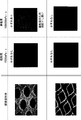
- FIG. 4 is a table for explaining the results of applying the electrode mixture paste on the current collector using the rotary screen plate 100 according to Example 1 and the rotary screen plate 400 according to Comparative Example 1.
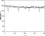
- FIG. 5 is a graph for explaining the results of applying the electrode mixture paste onto the current collector using the rotary screen plate 100 according to Example 1 and the rotary screen plate 400 according to Comparative Example 1.
- FIG. 6 is a perspective view illustrating a rotary screen plate 400 according to Comparative Example 1.
- the photographs shown in FIG. 3 were obtained by imaging the rotary screen plate 100 according to Example 1, the rotary screen plate according to Example 2, and the rotary screen plate 400 according to Comparative Example 1 with a scanning electron microscope. It is a photograph.
- the rotary screen plate 100 according to Example 1 is the rotary screen plate 100 according to the first embodiment of the present invention.
- the opening width of the injection hole 11 of the rotary screen plate 100 according to the example 1 is 90 ⁇ m, and the diameter of the wire constituting the mesh is 40 ⁇ m.
- the height at which the protruding portion 12 protrudes from the other portion of the outer peripheral surface 1 is 5 ⁇ m.
- the rotary screen plate according to Example 2 is obtained by winding a mesh (net) formed by knitting a wire into a cylindrical shape.
- the outer peripheral surface of the rotary screen plate according to the second embodiment is formed in a mesh shape.
- the intersection part of a wire and a wire protrudes toward the outer side of a cylinder rather than the other part.
- the rotary screen plate concerning Example 2 is what wound the mesh in the cylindrical shape, it has a joint.
- variety of the opening (mesh eyes) of the rotary screen plate concerning Example 2 is 87 micrometers, and the diameter of the wire which comprises the said mesh is 40 micrometers.
- the number of wires per inch of the rotary screen plate according to Example 2 is 200.
- the rotary screen plate 400 according to the comparative example 1 is a cylindrical seamless roll having a large number of through holes 401 formed by etching or laser processing.
- the arithmetic average roughness Ra of the outer peripheral surface 402 of the rotary screen plate 400 is less than 1 ⁇ m.
- the diameter of the through hole 401 of the rotary screen plate 400 is 90 ⁇ m.
- the seamless roll is made of stainless steel.
- Example 1 Example 2, and Comparative Example 1, a ternary positive electrode active material as an active material, polyvinylidene fluoride (PVDF) as a binder (binder), acetylene black (AB) as a conductive auxiliary agent, and a solvent N-methyl-2-pyrrolidone (NMP) was used.
- PVDF polyvinylidene fluoride
- AB acetylene black
- NMP solvent N-methyl-2-pyrrolidone
- a ternary positive electrode active material is a positive electrode active material containing cobalt, nickel, manganese or the like.
- the viscosity of the electrode mixture paste is 15 Pa ⁇ s (pascal per second) or 1000 Pa ⁇ s (pascal per second).
- the second row of the table shown in FIG. 3 indicates whether or not each plate has a joint.
- whether each plate contacts the current collector with a point (point contact) Indicates whether to contact with the surface (surface contact).
- the fourth row of the table shown in FIG. 3 shows whether or not fading occurs when an electrode mixture paste having a viscosity of 1000 Pa ⁇ s is applied on the current collector.
- the rotary screen plate 100 according to Example 1 and the rotary screen plate according to Example 2 did not cause fading, whereas the rotary screen plate 400 according to Comparative Example 1 caused fading.
- Example 1 and Example 2 the film thickness of the electrode mixture paste coated on the current collector was relatively uniform, whereas in Comparative Example 1, the film thickness was on the current collector.
- the film thickness of the applied electrode mixture paste is not uniform.
- the rotary screen plate concerning Example 2 has a joint, it cannot coat an electrode mixture paste continuously with respect to a collector.
- a photograph of the rotary screen plate 400 according to Comparative Example 1 is shown in the upper row, and a photograph of the rotary screen plate 100 according to Example 1 is shown in the lower row.
- the photograph shown in the first row of FIG. 4 is a photograph obtained by imaging the rotary screen plate 400 according to Comparative Example 1 and the rotary screen plate 100 according to Example 1 with a scanning electron microscope.
- the second column of the table shown in FIG. 4 when an electrode mixture paste having a viscosity of 15 Pa ⁇ s is applied on the current collector, the electrode mixture layer formed on the current collector The photograph obtained by imaging the surface with an optical microscope is shown.
- the third column of the table shown in FIG. 4 when an electrode mixture paste having a viscosity of 1000 Pa ⁇ s is applied on the current collector, the electrode mixture layer formed on the current collector The photograph obtained by imaging the surface with an optical microscope is shown.
- the rotary screen plate 100 according to Example 1 was used to apply either an electrode mixture paste having a viscosity of 15 Pa ⁇ s or an electrode mixture paste having a viscosity of 1000 Pa ⁇ s onto the current collector. Even if processed, the film thickness of the electrode mixture layer is relatively uniform. On the other hand, when the electrode mixture paste having a viscosity of 15 Pa ⁇ s is applied on the current collector by the rotary screen plate 400 according to Comparative Example 1, the film thickness of the electrode mixture layer is relatively uniform. When the electrode mixture paste having a viscosity of 1000 Pa ⁇ s is applied on the current collector, the film thickness of the electrode mixture layer is not uniform. That is, as the viscosity of the electrode mixture paste increases, the rotary screen plate 400 according to Comparative Example 1 becomes blurred.
- the vertical axis of the graph shown in FIG. 5 indicates the change (%) in the film thickness of the electrode mixture paste applied on the current collector, and the horizontal axis indicates the electrode mixture applied on the current collector.
- the length ( ⁇ m) in a predetermined cross section of the paste is shown.
- the change (%) in the film thickness of the electrode mixture paste applied on the current collector is that the film thickness of the electrode mixture paste at the position where the horizontal axis is 0 ⁇ m is 100%.
- the thick solid line indicates Example 1
- the thin solid line indicates Comparative Example 1.
- FIG. 5 shows a change in the film thickness of the electrode mixture paste when the electrode mixture paste having a viscosity of 1000 Pa ⁇ s is applied onto the current collector. As shown in FIG.
- an electrode mixture paste having a viscosity of 1000 Pa ⁇ s is collected using the rotary screen plate 100 according to Example 1 and the rotary screen plate according to Example 2.
- the film thickness of the electrode mixture paste applied on the current collector becomes relatively uniform.
- the electrode mixture paste having a viscosity of 1000 Pa ⁇ s is coated on the current collector using the rotary screen plate 400 according to Comparative Example 1, the electrode mixture coated on the current collector is used.
- the film thickness of the agent paste is not uniform.
- the outer peripheral surface 1 is in point contact with the current collector, whereas in the rotary screen plate 400 according to Comparative Example 1, It is considered that the outer peripheral surface 402 is in contact with the current collector on the surface. Specifically, when the outer peripheral surface 1 is in contact with the current collector at a point, the electrode mixture paste spreads sufficiently on the outer peripheral surface 1, whereas when the outer peripheral surface 402 is in contact with the current collector at the surface, This is probably because the electrode mixture paste does not spread sufficiently on the surface 402.
- a surface (hereinafter referred to as a contact surface) where the plate 500 shown in FIG. 7 is in contact with the metal foil (current collector) 700 is a flat surface.
- the surface (hereinafter referred to as the contact surface) where the plate 600 shown in FIG. 8 contacts the metal foil 700 is a surface having fine irregularities.
- the contact surface is in contact with the metal foil (current collector) 700 on the surface. Therefore, there is no gap between the contact surface and the surface of the metal foil 700, and the electrode mixture paste X having a high viscosity does not spread sufficiently on the contact surface. Thereby, the film thickness of the electrode mixture applied on the metal foil 700 becomes non-uniform.
- the contact surface is in contact with the metal foil 700 at a point. Therefore, an appropriate gap is formed between the contact surface and the surface of the metal foil 700, and the electrode mixture paste X having a high viscosity spreads sufficiently on the contact surface. Thereby, the electrode mixture paste can be applied to the metal foil 700 with a more uniform film thickness.
Landscapes
- Chemical & Material Sciences (AREA)
- Chemical Kinetics & Catalysis (AREA)
- Electrochemistry (AREA)
- General Chemical & Material Sciences (AREA)
- Engineering & Computer Science (AREA)
- Manufacturing & Machinery (AREA)
- Materials Engineering (AREA)
- Inorganic Chemistry (AREA)
- Mechanical Engineering (AREA)
- Battery Electrode And Active Subsutance (AREA)
- Printing Plates And Materials Therefor (AREA)
- Screen Printers (AREA)
- Application Of Or Painting With Fluid Materials (AREA)
Abstract
円筒体の外周面1に円筒体内部から集電体に対して電極合剤ペーストを射出する複数の射出孔11が設けられたロータリースクリーン版100であって、円筒体の外周面1に、当該外周面1の他の部分よりも当該円筒体の外側方向に突出する突出部12を備える。突出部12により、集電体とロータリースクリーン版100の外周面1との間に適度な隙間ができ、粉体の含有比率が高く、粘度の高い電極合剤ペーストであっても、ロータリースクリーン版100の外周面1の射出孔11以外の部分にも電極合剤ペーストが十分に広がる。そのため、より均一な膜厚で電極合剤ペーストを集電体に塗工することができる。
Description
本発明は、ロータリースクリーン版及び二次電池の製造方法に関する。
二次電極の電極体は、集電体(電極基材)上に電極合剤ペーストを塗工したものを巻回してなる。また、集電体上に塗工される電極合剤ペーストは、活物質、結合剤及び導電助剤等の粉体と、溶媒と、を混練して製造される。また、電極合剤ペーストは、例えば、ロータリースクリーン印刷等によって、集電体上に塗工される。
例えば、特許文献1には、電極合剤ペーストを集電体上に塗工するロータリースクリーン版が記載されている。特許文献1のロータリースクリーン版は、円筒形状のスクリーン版であり、その外周面に電極合剤ペーストを円筒の内側から外側へ押し出す多数の小孔を備えている。そして、当該小孔から電極合剤ペーストを押し出しながら、当該ロータリースクリーン版が集電体上を回動することにより、集電体上に電極合剤ペーストが塗工される。
例えば、特許文献1には、電極合剤ペーストを集電体上に塗工するロータリースクリーン版が記載されている。特許文献1のロータリースクリーン版は、円筒形状のスクリーン版であり、その外周面に電極合剤ペーストを円筒の内側から外側へ押し出す多数の小孔を備えている。そして、当該小孔から電極合剤ペーストを押し出しながら、当該ロータリースクリーン版が集電体上を回動することにより、集電体上に電極合剤ペーストが塗工される。
また、集電体上に電極合剤ペーストを塗工した後、電極合剤ペーストは乾燥される。そして、電極合剤ペーストの乾燥加工費及び材料費を低減させるため、電極合剤ペーストの作成に使用する溶媒量を減らし、電極合剤ペーストの粉体の含有比率を多くすることが検討されている。
しかしながら、電極合剤ペーストの粉体の含有比率を多くすると、電極合剤ペーストの粘度が高くなるため、集電体上に形成された電極合剤層にかすれが生じたり、電極合剤層の膜厚が不均一となったりしてしまうという問題がある。
具体的には、引用文献1に記載のロータリースクリーン版の外周面の小孔以外の部分は平滑な面を有しているため、ロータリースクリーン版の外周面の小孔以外の部分と集電体の表面とは、密着する。そのため、引用文献1に記載のロータリースクリーン版を用いて、粘度の高い電極合剤ペーストを集電体に塗工すると、当該ロータリースクリーン版の外周面の小孔以外の部分に電極合剤ペーストが広がらず、集電体上に形成された電極合剤層にかすれが生じたり、電極合剤層の膜厚が不均一となったりしてしまう可能性がある。これにより、集電体上に塗工される電極合剤ペーストの量が不足して電池容量が不足したり、Liが析出してしまったりするという問題が生じる。
具体的には、引用文献1に記載のロータリースクリーン版の外周面の小孔以外の部分は平滑な面を有しているため、ロータリースクリーン版の外周面の小孔以外の部分と集電体の表面とは、密着する。そのため、引用文献1に記載のロータリースクリーン版を用いて、粘度の高い電極合剤ペーストを集電体に塗工すると、当該ロータリースクリーン版の外周面の小孔以外の部分に電極合剤ペーストが広がらず、集電体上に形成された電極合剤層にかすれが生じたり、電極合剤層の膜厚が不均一となったりしてしまう可能性がある。これにより、集電体上に塗工される電極合剤ペーストの量が不足して電池容量が不足したり、Liが析出してしまったりするという問題が生じる。
本発明は、このような問題を解決するためになされたものであり、より均一な膜厚で電極合剤ペーストを集電体に塗工することができるロータリースクリーン版及び二次電池の製造方法を提供することを目的とするものである。
本発明の第1の態様にかかるロータリースクリーン版は、円筒体の外周面に前記円筒体内部から被印刷基材に対して印刷ペーストを射出する複数の射出孔が設けられたものである。また、前記円筒体の前記外周面に、当該外周面の他の部分よりも当該円筒体の外側方向に突出する突出部を備える。
本発明の第1の態様にかかるロータリースクリーン版によれば、円筒体の外周面の他の部分よりも当該円筒の外側方向に突出する突出部により、被印刷基材とロータリースクリーン版の外周面との間に適度な隙間ができ、粘度の高い印刷用ペーストであっても、ロータリースクリーン版の外周面の射出孔以外の部分にも印刷用ペーストが十分に広がる。そのため、より均一な膜厚で印刷用ペーストを被印刷基材に塗工することができる。換言すれば、より均一な膜厚で印刷用ペーストとしての電極合剤ペーストを被印刷基材としての集電体に塗工することができる。
本発明の第2の態様にかかるロータリースクリーン版は、円筒体の外周面に前記円筒体内部から集電体に対して電極合剤ペーストを射出する複数の射出孔が設けられたものである。また、前記円筒体の前記外周面に、当該外周面の他の部分よりも当該円筒体の外側方向に突出する突出部を備える。
本発明の第2の態様にかかるロータリースクリーン版によれば、円筒体の外周面の他の部分よりも当該円筒の外側方向に突出する突出部により、集電体とロータリースクリーン版の外周面との間に適度な隙間ができ、粉体の含有比率が高く、粘度の高い電極合剤ペーストであっても、ロータリースクリーン版の外周面の射出孔以外の部分にも電極合剤ペーストが十分に広がる。そのため、より均一な膜厚で電極合剤ペーストを集電体に塗工することができる。
本発明の第3の態様にかかる二次電池の製造方法は、前記円筒体の前記外周面の他の部分よりも当該円筒体の外側方向に突出する突出部を備えるロータリースクリーン版を用いて集電体に電極合剤ペーストを塗工する、塗工工程を備える。
本発明の第3の態様にかかる二次電池の製造方法によれば、より均一な膜厚で電極合剤ペーストを集電体に塗工することができる。
より均一な膜厚で電極合剤ペーストを集電体に塗工することができるロータリースクリーン版及び二次電池の製造方法を提供することができる。
実施の形態1
以下、図面を参照して本発明の実施の形態1について説明する。本発明の実施の形態1にかかるロータリースクリーン版100は、集電体(被印刷基材)に電極合剤ペースト(印刷用ペースト)を塗工するものである。
図1は、本発明の実施の形態1にかかるロータリースクリーン版100を説明する斜視図である。また、図1の右側には、ロータリースクリーン版100の一部を拡大して示す写真である。当該写真は、ロータリースクリーン版100を走査型電子顕微鏡によって撮像することにより得られた。図1に示すように、ロータリースクリーン版100は、円筒体の外周面1に複数の射出孔11を有する。また、電極合剤ペーストは、射出孔11を通って、当該円筒体の内部から集電体に対して射出される。
以下、図面を参照して本発明の実施の形態1について説明する。本発明の実施の形態1にかかるロータリースクリーン版100は、集電体(被印刷基材)に電極合剤ペースト(印刷用ペースト)を塗工するものである。
図1は、本発明の実施の形態1にかかるロータリースクリーン版100を説明する斜視図である。また、図1の右側には、ロータリースクリーン版100の一部を拡大して示す写真である。当該写真は、ロータリースクリーン版100を走査型電子顕微鏡によって撮像することにより得られた。図1に示すように、ロータリースクリーン版100は、円筒体の外周面1に複数の射出孔11を有する。また、電極合剤ペーストは、射出孔11を通って、当該円筒体の内部から集電体に対して射出される。
また、ロータリースクリーン版100は、当該円筒体の外周面1に、当該外周面1の他の部分よりも当該円筒体の外側方向に突出する突出部12を有する。具体的には、ロータリースクリーン版100は、円筒体の形状を有するメッシュ(網)である。そして、突出部12は、当該メッシュを構成する線材と線材との交点部に形成されている。換言すれば、突出部12は、ロータリースクリーン版100の外周面1において規則的に存在している。また、射出孔11は、当該メッシュの目により構成されている。
また、ロータリースクリーン版100は、当該円筒体の内部に圧送された電極合剤ペーストを射出孔11から押し出すスキージ(図示省略)等を備える。
そして、ロータリースクリーン版100の射出孔11から電極合剤ペーストを流出させながら、ロータリースクリーン版100が集電体上を回動する。これにより、電極合剤ペーストが集電体上に塗工される。
また、ロータリースクリーン版100は、電気鋳造により形成されている。
そして、ロータリースクリーン版100の射出孔11から電極合剤ペーストを流出させながら、ロータリースクリーン版100が集電体上を回動する。これにより、電極合剤ペーストが集電体上に塗工される。
また、ロータリースクリーン版100は、電気鋳造により形成されている。
次に、図2を参照しながら、本発明の実施の形態1にかかるロータリースクリーン版100の製造方法を説明する。図2では、電鋳鋳型200、メッシュ300、ロータリースクリーン版100の一部を拡大して示す。また、図2の右側の写真は、ロータリースクリーン版100の線材の交点部を走査型電子顕微鏡によって撮像することにより得られた断面写真である。
まず、図2に示すように、円柱形状の電鋳鋳型200を用いて電気鋳造を行って、当該電鋳鋳型200上にステンレス鋼(SUS)を電着させる。これにより、電鋳鋳型200上に、ステンレス鋼(SUS)からなる円筒形状のメッシュ(網)300を作製する。なお、電鋳鋳型200の表面には、所望する円筒形状のメッシュ300に相当する溝201が形成されている。
次に、電鋳鋳型200から円筒形状のメッシュ300を外し、メッシュ300に対してNi鍍金(ニッケルめっき)を施す。当該Ni鍍金により、メッシュ300を構成する線材と線材との交点部に突出部12が形成され、ロータリースクリーン版100が製造される。なお、ロータリースクリーン版100の射出孔11の開口幅は110μm以下であることが好ましい。
まず、図2に示すように、円柱形状の電鋳鋳型200を用いて電気鋳造を行って、当該電鋳鋳型200上にステンレス鋼(SUS)を電着させる。これにより、電鋳鋳型200上に、ステンレス鋼(SUS)からなる円筒形状のメッシュ(網)300を作製する。なお、電鋳鋳型200の表面には、所望する円筒形状のメッシュ300に相当する溝201が形成されている。
次に、電鋳鋳型200から円筒形状のメッシュ300を外し、メッシュ300に対してNi鍍金(ニッケルめっき)を施す。当該Ni鍍金により、メッシュ300を構成する線材と線材との交点部に突出部12が形成され、ロータリースクリーン版100が製造される。なお、ロータリースクリーン版100の射出孔11の開口幅は110μm以下であることが好ましい。
次に、本発明の実施の形態1にかかるロータリースクリーン版100を用いた二次電池の製造方法について説明する。
まず、混練機を用いて、活物質、結合剤、導電助剤、溶媒等を混練し、電極合剤ペーストを作成する(混練工程)。
次に、ロータリースクリーン版100を用いて、集電体上に電極合剤ペーストを塗工する(塗工工程)。
なお、本発明の実施の形態1にかかる塗工工程を経た後、乾燥工程、巻回工程等の複数の製造工程を経て、二次電池が製造される。
まず、混練機を用いて、活物質、結合剤、導電助剤、溶媒等を混練し、電極合剤ペーストを作成する(混練工程)。
次に、ロータリースクリーン版100を用いて、集電体上に電極合剤ペーストを塗工する(塗工工程)。
なお、本発明の実施の形態1にかかる塗工工程を経た後、乾燥工程、巻回工程等の複数の製造工程を経て、二次電池が製造される。
以上に説明した、本発明の実施の形態1にかかるロータリースクリーン版100及び二次電池の製造方法によれば、円筒体の外周面1の他の部分よりも当該円筒体の外側方向に突出する突出部12により、集電体とロータリースクリーン版100の外周面1との間に適度な隙間ができ、粉体の含有比率が高く、粘度の高い電極合剤ペーストであっても、ロータリースクリーン版100の外周面1の射出孔11以外の部分にも電極合剤ペーストが十分に広がる。そのため、より均一な膜厚で電極合剤ペーストを集電体に塗工することができる。
特に、突出部12は、ロータリースクリーン版100の外周面1において規則的に存在している。そのため、ロータリースクリーン版100の版表面全体において、集電体に塗工する電極合剤ペーストがかすれることを防止することができる。
また、ロータリースクリーン版100では、ロータリースクリーン版100の回動により強制的にロータリースクリーン版100が集電体から離れることができる。
また、ロータリースクリーン版100は電気鋳造により形成されるため繋ぎ目がなく、ロータリースクリーン版100が回動することにより、集電体に対して連続的に電極合剤ペーストを塗工することができる。
また、エッチング加工やレーザ加工を用いずにロータリースクリーン版100を製造することができるため、シームレスロールにエッチング加工やレーザ加工により貫通穴を形成したロータリースクリーン版に比べて、版に対するダメージが少なくて済む。
特に、突出部12は、ロータリースクリーン版100の外周面1において規則的に存在している。そのため、ロータリースクリーン版100の版表面全体において、集電体に塗工する電極合剤ペーストがかすれることを防止することができる。
また、ロータリースクリーン版100では、ロータリースクリーン版100の回動により強制的にロータリースクリーン版100が集電体から離れることができる。
また、ロータリースクリーン版100は電気鋳造により形成されるため繋ぎ目がなく、ロータリースクリーン版100が回動することにより、集電体に対して連続的に電極合剤ペーストを塗工することができる。
また、エッチング加工やレーザ加工を用いずにロータリースクリーン版100を製造することができるため、シームレスロールにエッチング加工やレーザ加工により貫通穴を形成したロータリースクリーン版に比べて、版に対するダメージが少なくて済む。
なお、電極合剤層の均一性は、電極合剤層の性能に不都合を生じない程度に均一であればよく、完全に均一でなくてもよい。すなわち、本発明にかかるロータリースクリーン版100によって集電体上に塗工された電極合剤層の膜厚は完全に均一であるものに限定されるものではない。また、塗工直後は溶媒があるため、目視により電極合剤層の膜厚の均一性を確認している。例えば、塗工範囲において、被印刷基材面(集電体の面)が確認される場合、電極合剤層の膜厚が不均一であると判断する。
次に、図3~図6を用いて、本発明の実施例1、実施例2及び比較例1について説明する。図3は、実施例1、実施例2及び比較例1を説明する表を示す。また、図4は、実施例1にかかるロータリースクリーン版100及び比較例1にかかるロータリースクリーン版400を用いて集電体上に電極合剤ペーストを塗工した結果を説明する表である。また、図5は、実施例1にかかるロータリースクリーン版100及び比較例1にかかるロータリースクリーン版400を用いて電極合剤ペーストを集電体上に塗工した結果を説明するグラフである。また、図6は、比較例1にかかるロータリースクリーン版400を説明する斜視図である。
図3に示す写真は、それぞれ、実施例1にかかるロータリースクリーン版100、実施例2にかかるロータリースクリーン版、比較例1にかかるロータリースクリーン版400を走査型電子顕微鏡によって撮像することにより得られた写真である。実施例1にかかるロータリースクリーン版100は、本発明の実施の形態1にかかるロータリースクリーン版100である。
また、実施例1にかかるロータリースクリーン版100の射出孔11の開口幅は90μmであり、当該メッシュを構成する線材の径は40μmである。また、突出部12が外周面1の他の部分から突出する高さは5μmである。
また、実施例2にかかるロータリースクリーン版は、線材を編んで形成されたメッシュ(網)を円筒形状に巻いたものである。換言すれば、実施例2にかかるロータリースクリーン版の外周面はメッシュ状に形成されている。なお、実施例2にかかるロータリースクリーン版は、線材を編んで形成されているため、線材と線材との交点部は他の部分よりも円筒の外側に向かって突出している。また、実施例2にかかるロータリースクリーン版は、メッシュを円筒形状に巻いたものであるため、繋ぎ目を有する。
また、実施例2にかかるロータリースクリーン版の開口(メッシュの目)の幅は87μmであり、当該メッシュを構成する線材の径は40μmである。また、実施例2にかかるロータリースクリーン版の1インチ当たりの線材の本数は200本である。
また、実施例2にかかるロータリースクリーン版の開口(メッシュの目)の幅は87μmであり、当該メッシュを構成する線材の径は40μmである。また、実施例2にかかるロータリースクリーン版の1インチ当たりの線材の本数は200本である。
また、比較例1にかかるロータリースクリーン版400は、図6に示すように、円筒形状のシームレスロールにエッチング加工やレーザ加工により多数の貫通穴401が形成されたものである。また、ロータリースクリーン版400の外周面402の算術平均粗さRaは1μm未満である。また、ロータリースクリーン版400の貫通穴401の直径は90μmである。なお、シームレスロールは、ステンレス鋼より形成されている。
また、実施例1、実施例2及び比較例1において、活物質として3元系正極活物質、結合剤(バインダ)としてポリフッ化ビニリデン(PVDF)、導電助剤としてアセチレンブラック(AB)、溶媒としてN-メチル-2-ピロリドン(NMP)を用いた。3元系正極活物質とは、コバルト、ニッケル、マンガン等を含む正極活物質である。
また、電極合剤ペーストの粘度は、15Pa・s(パスカル毎秒)又は1000Pa・s(パスカル毎秒)である。
また、電極合剤ペーストの粘度は、15Pa・s(パスカル毎秒)又は1000Pa・s(パスカル毎秒)である。
図3に示す表の2行目には、それぞれの版が繋ぎ目を有するか否かを示し、3行目には、それぞれの版が集電体と点で接触するか(点接触)、面で接触するか(面接触)を示した。また、図3に示す表の4行目には、粘度が1000Pa・sの電極合剤ペーストを集電体上に塗工した場合にかすれが生じるか否かを示した。
図3に示すように、実施例1にかかるロータリースクリーン版100及び実施例2にかかるロータリースクリーン版ではかすれが生じないのに対し、比較例1にかかるロータリースクリーン版400ではかすれが生じた。換言すれば、実施例1、実施例2では、集電体上に塗工された電極合剤ペーストの膜厚は比較的均一であったのに対し、比較例1では、集電体上に塗工された電極合剤ペーストの膜厚は不均一となっている。
なお、実施例2にかかるロータリースクリーン版は繋ぎ目を有するため、集電体に対して連続的に電極合剤ペーストを塗工することができない。
図3に示すように、実施例1にかかるロータリースクリーン版100及び実施例2にかかるロータリースクリーン版ではかすれが生じないのに対し、比較例1にかかるロータリースクリーン版400ではかすれが生じた。換言すれば、実施例1、実施例2では、集電体上に塗工された電極合剤ペーストの膜厚は比較的均一であったのに対し、比較例1では、集電体上に塗工された電極合剤ペーストの膜厚は不均一となっている。
なお、実施例2にかかるロータリースクリーン版は繋ぎ目を有するため、集電体に対して連続的に電極合剤ペーストを塗工することができない。
また、図4に示す表の1列目には、上段に比較例1にかかるロータリースクリーン版400の写真を示し、下段に実施例1にかかるロータリースクリーン版100の写真を示す。図4の1列目に示す写真は、比較例1にかかるロータリースクリーン版400及び実施例1にかかるロータリースクリーン版100を走査型電子顕微鏡によって撮像することにより得られた写真である。
また、図4に示す表の2列目には、粘度が15Pa・sである電極合剤ペーストを集電体上に塗工した場合に、集電体上に形成された電極合剤層の表面を光学顕微鏡で撮像して得られた写真を示す。また、図4に示す表の3列目には、粘度が1000Pa・sである電極合剤ペーストを集電体上に塗工した場合に、集電体上に形成された電極合剤層の表面を光学顕微鏡で撮像して得られた写真を示す。
また、図4に示す表の2列目には、粘度が15Pa・sである電極合剤ペーストを集電体上に塗工した場合に、集電体上に形成された電極合剤層の表面を光学顕微鏡で撮像して得られた写真を示す。また、図4に示す表の3列目には、粘度が1000Pa・sである電極合剤ペーストを集電体上に塗工した場合に、集電体上に形成された電極合剤層の表面を光学顕微鏡で撮像して得られた写真を示す。
図4に示すように、実施例1にかかるロータリースクリーン版100によって、粘度が15Pa・sである電極合剤ペースト及び粘度が1000Pa・sである電極合剤ペーストの何れを集電体上に塗工しても、電極合剤層の膜厚は比較的均一となっている。
一方、比較例1にかかるロータリースクリーン版400によって、粘度が15Pa・sである電極合剤ペーストを集電体上に塗工した場合、電極合剤層の膜厚は比較的均一であるが、粘度が1000Pa・sである電極合剤ペーストを集電体上に塗工した場合、電極合剤層の膜厚が不均一となっている。すなわち、電極合剤ペーストの粘度が高くなるほど、比較例1にかかるロータリースクリーン版400では、かすれが生じてしまう。
一方、比較例1にかかるロータリースクリーン版400によって、粘度が15Pa・sである電極合剤ペーストを集電体上に塗工した場合、電極合剤層の膜厚は比較的均一であるが、粘度が1000Pa・sである電極合剤ペーストを集電体上に塗工した場合、電極合剤層の膜厚が不均一となっている。すなわち、電極合剤ペーストの粘度が高くなるほど、比較例1にかかるロータリースクリーン版400では、かすれが生じてしまう。
図5に示すグラフの縦軸は、集電体上に塗工された電極合剤ペーストの膜厚の変化(%)を示し、横軸は、集電体上に塗工された電極合剤ペーストの所定の断面における長さ(μm)を示す。なお、集電体上に塗工された電極合剤ペーストの膜厚の変化(%)は、横軸が0μmの位置における電極合剤ペーストの膜厚を100%としている。図5において、太い実線が実施例1を示し、細い実線が比較例1を示す。また、図5は、粘度が1000Pa・sである電極合剤ペーストを集電体上に塗工した場合の電極合剤ペーストの膜厚の変化を示している。
図5に示すように、実施例1にかかるロータリースクリーン版100により電極合剤ペーストを集電体上に塗工した場合、集電体上に塗工された電極合剤ペーストの膜厚は、大きく変化していない。換言すれば、実施例1にかかるロータリースクリーン版100により粘度が1000Pa・sである電極合剤ペーストを集電体上に塗工した場合、集電体上に塗工された電極合剤ペーストの膜厚は比較的均一となっている。
一方、比較例1にかかるロータリースクリーン版400により電極合剤ペーストを集電体上に塗工した場合、集電体上に塗工された電極合剤ペーストの膜厚は、10%~15%変化する部分(図5の矢印で示す箇所)が発生した。換言すれば、比較例1にかかるロータリースクリーン版400により粘度が1000Pa・sである電極合剤ペーストを集電体上に塗工した場合、集電体上に塗工された電極合剤ペーストの膜厚は不均一となっている。
図5に示すように、実施例1にかかるロータリースクリーン版100により電極合剤ペーストを集電体上に塗工した場合、集電体上に塗工された電極合剤ペーストの膜厚は、大きく変化していない。換言すれば、実施例1にかかるロータリースクリーン版100により粘度が1000Pa・sである電極合剤ペーストを集電体上に塗工した場合、集電体上に塗工された電極合剤ペーストの膜厚は比較的均一となっている。
一方、比較例1にかかるロータリースクリーン版400により電極合剤ペーストを集電体上に塗工した場合、集電体上に塗工された電極合剤ペーストの膜厚は、10%~15%変化する部分(図5の矢印で示す箇所)が発生した。換言すれば、比較例1にかかるロータリースクリーン版400により粘度が1000Pa・sである電極合剤ペーストを集電体上に塗工した場合、集電体上に塗工された電極合剤ペーストの膜厚は不均一となっている。
図3、図4、図5に示すように、実施例1にかかるロータリースクリーン版100及び実施例2にかかるロータリースクリーン版を用いて、粘度が1000Pa・sである電極合剤ペーストを集電体上に塗工した場合、集電体上に塗工された電極合剤ペーストの膜厚は比較的均一となる。これに対し、比較例1にかかるロータリースクリーン版400を用いて、粘度が1000Pa・sである電極合剤ペーストを集電体上に塗工した場合、集電体上に塗工された電極合剤ペーストの膜厚は不均一となる。
これは、実施例1にかかるロータリースクリーン版100及び実施例2にかかるロータリースクリーン版では、外周面1が集電体と点で接触するのに対し、比較例1にかかるロータリースクリーン版400では、外周面402が集電体と面で接触するためと考えられる。具体的には、外周面1が集電体と点で接触する場合、外周面1において電極合剤ペーストが十分に広がるのに対し、外周面402が集電体と面で接触する場合、外周面402において電極合剤ペーストが十分に広がらないためと考えられる。
これは、実施例1にかかるロータリースクリーン版100及び実施例2にかかるロータリースクリーン版では、外周面1が集電体と点で接触するのに対し、比較例1にかかるロータリースクリーン版400では、外周面402が集電体と面で接触するためと考えられる。具体的には、外周面1が集電体と点で接触する場合、外周面1において電極合剤ペーストが十分に広がるのに対し、外周面402が集電体と面で接触する場合、外周面402において電極合剤ペーストが十分に広がらないためと考えられる。
より具体的に、図7、図8を参照して、集電体と版との接触と、集電体上に形成される電極合剤層の膜厚との関係を説明する。図7に示す版500が金属箔(集電体)700と接触する面(以下、接触面と称する)は、平坦な面となっている。一方、図8に示す版600が金属箔700と接触する面(以下、接触面と称する)は細かな凹凸を有する面となっている。
図7に示す版500の場合、接触面は金属箔(集電体)700と面で接触する。そのため、接触面と金属箔700の表面との間に隙間ができず、粘度の高い電極合剤ペーストXが接触面において十分に広がらない。これにより、金属箔700上に塗工された電極合剤の膜厚が不均一となってしまう。
一方、図8に示す版600の場合、接触面は金属箔700と点で接触する。そのため、接触面と金属箔700の表面との間に適度な隙間ができ、粘度の高い電極合剤ペーストXが接触面において十分に広がる。これにより、より均一な膜厚で電極合剤ペーストを金属箔700に塗工することができる。
なお、本発明は上記実施の形態に限られたものではなく、趣旨を逸脱しない範囲で適宜変更することが可能である。
この出願は、2013年11月22日に出願された日本出願特願2013-242173を基礎とする優先権を主張し、その開示の全てをここに取り込む。
より均一な膜厚で電極合剤ペーストを集電体に塗工することができるロータリースクリーン版及び二次電池の製造方法を提供することができる。
1 外周面
11 射出孔
12 突出部
100 ロータリースクリーン版
200 電鋳鋳型
201 溝
300 メッシュ
11 射出孔
12 突出部
100 ロータリースクリーン版
200 電鋳鋳型
201 溝
300 メッシュ
Claims (5)
- 円筒体の外周面に前記円筒体内部から被印刷基材に対して印刷ペーストを射出する複数の射出孔が設けられたロータリースクリーン版であって、
前記円筒体の前記外周面に、当該外周面の他の部分よりも当該円筒体の外側方向に突出する突出部を備える、ロータリースクリーン版。 - 円筒体の外周面に前記円筒体内部から集電体に対して電極合剤ペーストを射出する複数の射出孔が設けられたロータリースクリーン版であって、
前記円筒体の前記外周面に、当該外周面の他の部分よりも当該円筒体の外側方向に突出する突出部を備える、ロータリースクリーン版。 - 前記ロータリースクリーン版は、前記円筒体の形状を有するメッシュであり、
前記突出部は、前記メッシュを構成する線材と線材との交点部に形成されている、請求項1又は2に記載のロータリースクリーン版。 - 前記ロータリースクリーン版は、電気鋳造により形成されている、請求項3に記載のロータリースクリーン版。
- 請求項1乃至4の何れか一項に記載のロータリースクリーン版を用いて集電体に電極合剤ペーストを塗工する塗工工程を備える、二次電池の製造方法。
Priority Applications (2)
| Application Number | Priority Date | Filing Date | Title |
|---|---|---|---|
| US15/028,544 US20160254524A1 (en) | 2013-11-22 | 2014-10-22 | Rotary screen plate and method of manufacturing secondary battery |
| CN201480054477.6A CN105593024A (zh) | 2013-11-22 | 2014-10-22 | 轮转丝网印版和二次电池的制造方法 |
Applications Claiming Priority (2)
| Application Number | Priority Date | Filing Date | Title |
|---|---|---|---|
| JP2013-242173 | 2013-11-22 | ||
| JP2013242173A JP6003872B2 (ja) | 2013-11-22 | 2013-11-22 | ロータリースクリーン版及び二次電池の製造方法 |
Publications (1)
| Publication Number | Publication Date |
|---|---|
| WO2015075866A1 true WO2015075866A1 (ja) | 2015-05-28 |
Family
ID=53179161
Family Applications (1)
| Application Number | Title | Priority Date | Filing Date |
|---|---|---|---|
| PCT/JP2014/005352 Ceased WO2015075866A1 (ja) | 2013-11-22 | 2014-10-22 | ロータリースクリーン版及び二次電池の製造方法 |
Country Status (4)
| Country | Link |
|---|---|
| US (1) | US20160254524A1 (ja) |
| JP (1) | JP6003872B2 (ja) |
| CN (1) | CN105593024A (ja) |
| WO (1) | WO2015075866A1 (ja) |
Citations (6)
| Publication number | Priority date | Publication date | Assignee | Title |
|---|---|---|---|---|
| JPH03162995A (ja) * | 1989-11-22 | 1991-07-12 | Kyushu Hitachi Maxell Ltd | スクリーン印刷用メッシュ、並びにその製造方法 |
| JP2002164043A (ja) * | 2000-11-27 | 2002-06-07 | Sony Corp | 電極製造方法 |
| JP2005047216A (ja) * | 2003-07-31 | 2005-02-24 | Minami Kk | スクリーン印刷装置 |
| JP2006335045A (ja) * | 2005-06-06 | 2006-12-14 | Murata Mfg Co Ltd | スクリーン印刷版およびその製造方法、積層セラミック電子部品の製造方法 |
| JP2010017887A (ja) * | 2008-07-08 | 2010-01-28 | Fuchigami Micro:Kk | メッシュシート及びメッシュシートの製造方法 |
| JP2010094687A (ja) * | 2008-10-14 | 2010-04-30 | Kobe Steel Ltd | 圧延ロール及びスクリーン印刷用メッシュ |
Family Cites Families (12)
| Publication number | Priority date | Publication date | Assignee | Title |
|---|---|---|---|---|
| US3482300A (en) * | 1966-10-31 | 1969-12-09 | Screen Printing Systems Inc | Printing screen and method of making same |
| JPS6482944A (en) * | 1987-09-25 | 1989-03-28 | Toshiba Corp | Printing screen plate and its processing |
| JPH06328873A (ja) * | 1993-05-18 | 1994-11-29 | Murata Mfg Co Ltd | スクリーン印刷用刷版 |
| US7134389B2 (en) * | 2002-02-22 | 2006-11-14 | Minami Co., Ltd. | Screen printing apparatus |
| JP5018062B2 (ja) * | 2006-12-15 | 2012-09-05 | 株式会社日立プラントテクノロジー | ハンダボール印刷装置 |
| CN201020906Y (zh) * | 2007-04-23 | 2008-02-13 | 无锡美微科技有限公司 | 一种电铸金属膜丝网版 |
| NL2003627C2 (en) * | 2009-10-12 | 2011-04-13 | Stork Prints Bv | Screen printing. |
| MX341955B (es) * | 2010-04-15 | 2016-09-08 | 3M Innovative Properties Co | Articulos retrorreflectantes que incluyen areas opticamente activas y areas opticamente inactivas. |
| DE102010021062A1 (de) * | 2010-05-19 | 2011-11-24 | Gallus Ferd. Rüesch AG | Flächiges Siebmaterial und Sieb |
| JP5325839B2 (ja) * | 2010-06-16 | 2013-10-23 | 株式会社コベルコ科研 | スクリーン印刷用メッシュ部材 |
| CN103361680B (zh) * | 2012-04-10 | 2017-06-06 | 昆山允升吉光电科技有限公司 | 电铸平面丝网 |
| CN202911269U (zh) * | 2012-05-23 | 2013-05-01 | 昆山允升吉光电科技有限公司 | 一种具有组合结构的掩膜板 |
-
2013
- 2013-11-22 JP JP2013242173A patent/JP6003872B2/ja active Active
-
2014
- 2014-10-22 WO PCT/JP2014/005352 patent/WO2015075866A1/ja not_active Ceased
- 2014-10-22 CN CN201480054477.6A patent/CN105593024A/zh active Pending
- 2014-10-22 US US15/028,544 patent/US20160254524A1/en not_active Abandoned
Patent Citations (6)
| Publication number | Priority date | Publication date | Assignee | Title |
|---|---|---|---|---|
| JPH03162995A (ja) * | 1989-11-22 | 1991-07-12 | Kyushu Hitachi Maxell Ltd | スクリーン印刷用メッシュ、並びにその製造方法 |
| JP2002164043A (ja) * | 2000-11-27 | 2002-06-07 | Sony Corp | 電極製造方法 |
| JP2005047216A (ja) * | 2003-07-31 | 2005-02-24 | Minami Kk | スクリーン印刷装置 |
| JP2006335045A (ja) * | 2005-06-06 | 2006-12-14 | Murata Mfg Co Ltd | スクリーン印刷版およびその製造方法、積層セラミック電子部品の製造方法 |
| JP2010017887A (ja) * | 2008-07-08 | 2010-01-28 | Fuchigami Micro:Kk | メッシュシート及びメッシュシートの製造方法 |
| JP2010094687A (ja) * | 2008-10-14 | 2010-04-30 | Kobe Steel Ltd | 圧延ロール及びスクリーン印刷用メッシュ |
Also Published As
| Publication number | Publication date |
|---|---|
| US20160254524A1 (en) | 2016-09-01 |
| JP2015103353A (ja) | 2015-06-04 |
| CN105593024A (zh) | 2016-05-18 |
| JP6003872B2 (ja) | 2016-10-05 |
Similar Documents
| Publication | Publication Date | Title |
|---|---|---|
| US8920522B2 (en) | Battery manufacturing method and battery | |
| US9583755B2 (en) | Method for manufacturing lithium ion secondary battery | |
| JP6525944B2 (ja) | リチウムイオン電池電極フィルムの多孔率の変化を生み出す方法 | |
| JP2010080128A (ja) | 電極 | |
| JP5288223B2 (ja) | 電池用電極の製造方法 | |
| WO2015049835A1 (ja) | リチウムイオン二次電池 | |
| JP2015138619A (ja) | 非水電解質二次電池の負極の製造方法、および非水電解質二次電池の負極の製造装置 | |
| CN104953090A (zh) | 电池用电极的制造方法以及制造装置、电极结构体 | |
| US20150194680A1 (en) | Lithium-ion secondary battery | |
| US20150303002A1 (en) | Capacitor and manufacturing method thereof | |
| WO2007083606A1 (ja) | 印刷用マスクおよびこれを用いた太陽電池の製造方法 | |
| JP2010080127A (ja) | 電極製造方法及び電極製造装置 | |
| JP2005211871A (ja) | ダイノズルおよび電極板の作製方法 | |
| DE102012005229B4 (de) | Verfahren zum Herstellen einer Batteriezelle und Batteriezelle | |
| JP2015176842A (ja) | リチウムイオン二次電池電極用シート製造装置,リチウムイオン二次電池電極用シートの製造方法およびリチウムイオン二次電池の製造方法 | |
| JP6003872B2 (ja) | ロータリースクリーン版及び二次電池の製造方法 | |
| JP2018032604A (ja) | 電極製造装置 | |
| JP2018018680A (ja) | 電極の製造方法 | |
| JP6372334B2 (ja) | 電極の製造装置及び電極の製造方法 | |
| JP4530651B2 (ja) | 太陽電池の製造方法 | |
| JP2015053203A (ja) | ロータリースクリーン及び二次電池の製造方法 | |
| JP4967411B2 (ja) | 多孔質耐熱層の形成方法および多孔質耐熱層の形成装置 | |
| JP2012146480A (ja) | 電極の製造方法、電池用電極および電池 | |
| JP2022128287A (ja) | グラビア版、グラビア印刷機及び積層型電子部品の製造方法 | |
| JP5560836B2 (ja) | 電子部品のパターン印刷方法および電子部品の製造方法 |
Legal Events
| Date | Code | Title | Description |
|---|---|---|---|
| 121 | Ep: the epo has been informed by wipo that ep was designated in this application |
Ref document number: 14864342 Country of ref document: EP Kind code of ref document: A1 |
|
| WWE | Wipo information: entry into national phase |
Ref document number: 15028544 Country of ref document: US |
|
| NENP | Non-entry into the national phase |
Ref country code: DE |
|
| 122 | Ep: pct application non-entry in european phase |
Ref document number: 14864342 Country of ref document: EP Kind code of ref document: A1 |