WO2015072455A1 - 音響透過性部材 - Google Patents
音響透過性部材 Download PDFInfo
- Publication number
- WO2015072455A1 WO2015072455A1 PCT/JP2014/079853 JP2014079853W WO2015072455A1 WO 2015072455 A1 WO2015072455 A1 WO 2015072455A1 JP 2014079853 W JP2014079853 W JP 2014079853W WO 2015072455 A1 WO2015072455 A1 WO 2015072455A1
- Authority
- WO
- WIPO (PCT)
- Prior art keywords
- sound
- layer
- thickness
- layers
- transmitting member
- Prior art date
Links
Images


Classifications
-
- G—PHYSICS
- G01—MEASURING; TESTING
- G01S—RADIO DIRECTION-FINDING; RADIO NAVIGATION; DETERMINING DISTANCE OR VELOCITY BY USE OF RADIO WAVES; LOCATING OR PRESENCE-DETECTING BY USE OF THE REFLECTION OR RERADIATION OF RADIO WAVES; ANALOGOUS ARRANGEMENTS USING OTHER WAVES
- G01S7/00—Details of systems according to groups G01S13/00, G01S15/00, G01S17/00
- G01S7/52—Details of systems according to groups G01S13/00, G01S15/00, G01S17/00 of systems according to group G01S15/00
- G01S7/521—Constructional features
-
- B—PERFORMING OPERATIONS; TRANSPORTING
- B32—LAYERED PRODUCTS
- B32B—LAYERED PRODUCTS, i.e. PRODUCTS BUILT-UP OF STRATA OF FLAT OR NON-FLAT, e.g. CELLULAR OR HONEYCOMB, FORM
- B32B25/00—Layered products comprising a layer of natural or synthetic rubber
- B32B25/04—Layered products comprising a layer of natural or synthetic rubber comprising rubber as the main or only constituent of a layer, which is next to another layer of the same or of a different material
- B32B25/08—Layered products comprising a layer of natural or synthetic rubber comprising rubber as the main or only constituent of a layer, which is next to another layer of the same or of a different material of synthetic resin
-
- B—PERFORMING OPERATIONS; TRANSPORTING
- B32—LAYERED PRODUCTS
- B32B—LAYERED PRODUCTS, i.e. PRODUCTS BUILT-UP OF STRATA OF FLAT OR NON-FLAT, e.g. CELLULAR OR HONEYCOMB, FORM
- B32B27/00—Layered products comprising a layer of synthetic resin
- B32B27/18—Layered products comprising a layer of synthetic resin characterised by the use of special additives
- B32B27/20—Layered products comprising a layer of synthetic resin characterised by the use of special additives using fillers, pigments, thixotroping agents
-
- B—PERFORMING OPERATIONS; TRANSPORTING
- B32—LAYERED PRODUCTS
- B32B—LAYERED PRODUCTS, i.e. PRODUCTS BUILT-UP OF STRATA OF FLAT OR NON-FLAT, e.g. CELLULAR OR HONEYCOMB, FORM
- B32B7/00—Layered products characterised by the relation between layers; Layered products characterised by the relative orientation of features between layers, or by the relative values of a measurable parameter between layers, i.e. products comprising layers having different physical, chemical or physicochemical properties; Layered products characterised by the interconnection of layers
- B32B7/02—Physical, chemical or physicochemical properties
- B32B7/022—Mechanical properties
-
- B—PERFORMING OPERATIONS; TRANSPORTING
- B63—SHIPS OR OTHER WATERBORNE VESSELS; RELATED EQUIPMENT
- B63B—SHIPS OR OTHER WATERBORNE VESSELS; EQUIPMENT FOR SHIPPING
- B63B49/00—Arrangements of nautical instruments or navigational aids
-
- H—ELECTRICITY
- H04—ELECTRIC COMMUNICATION TECHNIQUE
- H04R—LOUDSPEAKERS, MICROPHONES, GRAMOPHONE PICK-UPS OR LIKE ACOUSTIC ELECTROMECHANICAL TRANSDUCERS; DEAF-AID SETS; PUBLIC ADDRESS SYSTEMS
- H04R1/00—Details of transducers, loudspeakers or microphones
- H04R1/44—Special adaptations for subaqueous use, e.g. for hydrophone
-
- B—PERFORMING OPERATIONS; TRANSPORTING
- B32—LAYERED PRODUCTS
- B32B—LAYERED PRODUCTS, i.e. PRODUCTS BUILT-UP OF STRATA OF FLAT OR NON-FLAT, e.g. CELLULAR OR HONEYCOMB, FORM
- B32B2250/00—Layers arrangement
- B32B2250/05—5 or more layers
-
- B—PERFORMING OPERATIONS; TRANSPORTING
- B32—LAYERED PRODUCTS
- B32B—LAYERED PRODUCTS, i.e. PRODUCTS BUILT-UP OF STRATA OF FLAT OR NON-FLAT, e.g. CELLULAR OR HONEYCOMB, FORM
- B32B2262/00—Composition or structural features of fibres which form a fibrous or filamentary layer or are present as additives
- B32B2262/10—Inorganic fibres
- B32B2262/106—Carbon fibres, e.g. graphite fibres
-
- B—PERFORMING OPERATIONS; TRANSPORTING
- B32—LAYERED PRODUCTS
- B32B—LAYERED PRODUCTS, i.e. PRODUCTS BUILT-UP OF STRATA OF FLAT OR NON-FLAT, e.g. CELLULAR OR HONEYCOMB, FORM
- B32B2307/00—Properties of the layers or laminate
- B32B2307/10—Properties of the layers or laminate having particular acoustical properties
-
- B—PERFORMING OPERATIONS; TRANSPORTING
- B32—LAYERED PRODUCTS
- B32B—LAYERED PRODUCTS, i.e. PRODUCTS BUILT-UP OF STRATA OF FLAT OR NON-FLAT, e.g. CELLULAR OR HONEYCOMB, FORM
- B32B2307/00—Properties of the layers or laminate
- B32B2307/50—Properties of the layers or laminate having particular mechanical properties
- B32B2307/51—Elastic
-
- B—PERFORMING OPERATIONS; TRANSPORTING
- B32—LAYERED PRODUCTS
- B32B—LAYERED PRODUCTS, i.e. PRODUCTS BUILT-UP OF STRATA OF FLAT OR NON-FLAT, e.g. CELLULAR OR HONEYCOMB, FORM
- B32B2605/00—Vehicles
- B32B2605/12—Ships
-
- B—PERFORMING OPERATIONS; TRANSPORTING
- B63—SHIPS OR OTHER WATERBORNE VESSELS; RELATED EQUIPMENT
- B63B—SHIPS OR OTHER WATERBORNE VESSELS; EQUIPMENT FOR SHIPPING
- B63B2201/00—Signalling devices
- B63B2201/18—Sonar
-
- H—ELECTRICITY
- H04—ELECTRIC COMMUNICATION TECHNIQUE
- H04R—LOUDSPEAKERS, MICROPHONES, GRAMOPHONE PICK-UPS OR LIKE ACOUSTIC ELECTROMECHANICAL TRANSDUCERS; DEAF-AID SETS; PUBLIC ADDRESS SYSTEMS
- H04R1/00—Details of transducers, loudspeakers or microphones
- H04R1/02—Casings; Cabinets ; Supports therefor; Mountings therein
- H04R1/026—Supports for loudspeaker casings
-
- H—ELECTRICITY
- H04—ELECTRIC COMMUNICATION TECHNIQUE
- H04R—LOUDSPEAKERS, MICROPHONES, GRAMOPHONE PICK-UPS OR LIKE ACOUSTIC ELECTROMECHANICAL TRANSDUCERS; DEAF-AID SETS; PUBLIC ADDRESS SYSTEMS
- H04R1/00—Details of transducers, loudspeakers or microphones
- H04R1/02—Casings; Cabinets ; Supports therefor; Mountings therein
- H04R1/028—Casings; Cabinets ; Supports therefor; Mountings therein associated with devices performing functions other than acoustics, e.g. electric candles
Definitions
- the present invention relates to a sound transmission member having sound transmission characteristics.
- a sound transmission member having sound transmission has been used as a sound transmission region of a marine sonar device or the like.
- steel is representative, but as an improved structure, a rubber sound-transmitting member called a so-called rubber dome or rubber window is known.
- These conventional sound-transmitting members basically have a single-layer structure, and can obtain good sound-transmitting characteristics in a low-frequency region of several kHz or less, but are difficult to apply to a high-frequency band of 20 kHz or more.
- Patent Document 1 proposes a sound transmissive member using a sandwich structure in which both surfaces of a core layer are covered with a skin layer.
- FIG. 13 is an explanatory view showing the structure of a sound transmissive member according to the prior art.
- the sound transmitting member 130 shown in FIG. 13 uses 5 mm thick natural rubber for the core layer 1302 and 2 mm thick CFRP (Carbon fiber Reinforced Plastics) for the skin layer 1304.
- CFRP Carbon fiber Reinforced Plastics
- the sound transmission member that transmits the frequency f satisfying the following formulas (5) and (6) is formed. be able to.
- dc is the thickness of the core layer 1302
- C is the speed of sound in the core layer 1302
- C0 is the speed of sound in the surrounding fluid.
- a viscoelastic body such as rubber or urethane is used for the core layer having the conventional structure shown in FIG.
- Such a viscoelastic body has temperature characteristics, and the speed of sound in the viscoelastic body (C in the above formula (5)) also changes with changes in temperature.
- the sound velocity of the surrounding fluid (C0 in the above equation (5)) also changes depending on the temperature. For this reason, a deviation occurs in the frequency f shown in the above equation (6) depending on the temperature, which greatly affects the system performance.
- FIG. 14 is a graph showing the transmission characteristics of the sound transmission member shown in FIG.
- the vertical axis represents the transmission loss IL
- the horizontal axis represents the frequency.
- reference numeral 1402 is an actual measurement value obtained by actually measuring the sound transmission characteristics of the sound transmission member shown in FIG.
- Reference numeral 1404 denotes a calculated value obtained by modeling acoustic transmission characteristics in water at a water temperature of 20 ° C. from the actual measurement value indicated by reference numeral 1402, and reference numeral 1406 denotes acoustic transmission characteristics in water at a water temperature of 16 ° C. based on the calculated values indicated by reference numeral 1404. This is the calculated value.
- the transmission loss at a frequency of 150 kHz indicated by an arrow in FIG. 14 was 0.6 dB (1 dB or less) at a water temperature of 20 ° C., but increased to 3.5 dB at a water temperature of 16 ° C.
- the present invention has been made in view of the above-described problems of the prior art, and an object thereof is to provide an acoustically transmissive member capable of obtaining a wide acoustic transmission band in a high frequency region.
- the sound transmission member according to the invention of claim 1 is a planar sound transmission member having sound transmission properties, and is provided between two skin layers. N + 1 core layers and N intermediate layers are alternately laminated, and the skin layer and the intermediate layer are formed of a material having a higher elastic modulus than the core layer.
- the sound transmission member according to the invention of claim 2 is characterized in that the sound transmission member has a predetermined acoustic frequency band as a transmission frequency band, and the thickness dc of the core layer has a maximum frequency fm of the transmission frequency band and the The following formulas (1) and (2) are satisfied with respect to the wavelength ⁇ m of the sound wave at the maximum frequency fm.
- the thickness of the intermediate layer is 0.2 to 3 times the thickness of the skin layer, and the thickness of the intermediate layer and the skin layer is It is 0.1 mm or more.
- the acoustically transparent member according to the invention of claim 4 is characterized in that the skin layer and the intermediate layer are made of a material having an elastic modulus of 100 MPa or more and 350 GPa or less.
- the sound-transmitting member according to the invention of claim 5 is characterized in that the skin layer and the intermediate layer are formed of one of fiber reinforced plastic, plastic, and metal.
- the sound transmission member according to the invention of claim 6 is characterized in that the core layer is formed of a viscoelastic body or plastic.
- the acoustically transparent member according to the invention of claim 7 is characterized in that the core layer is formed by injecting glass microballoons into the viscoelastic body or the plastic, and the density and elastic modulus are formed to predetermined values.
- the acoustically permeable member according to the invention of claim 8 is a material in which the difference between the acoustic impedance of the material forming the core layer and the acoustic impedance of the fluid surrounding the acoustically permeable member is the material forming the core layer. It is 50% or less of the acoustic impedance.
- the sound-transmitting member according to the invention of claim 9 is characterized in that a protective layer is provided on the surface of the two skin layers opposite to the side laminated on the core layer.
- the first aspect of the present invention since a plurality of core layers that are damping layers are provided, vibrations are less likely to be excited, noise due to vibrations of devices using the sound transmitting member is reduced, and external Noise due to the surrounding fluid can be suppressed, and the performance of equipment and the like in which the sound transmitting member is used can be improved.
- a sound transmission region (window region) continuous up to the high frequency region can be formed, it is affected by a change in characteristics due to the influence of manufacturing variation, temperature, etc. in each sound transmission member. Therefore, good sound transmission characteristics can be obtained.
- variation in each sound permeable member 10 can be accept
- strength of a sound-transmitting member is securable by making thickness of an intermediate
- the skin layer and the intermediate layer can be formed of various materials. According to the invention of claim 5, excellent sound transmission characteristics can be obtained while securing the strength of the sound transmission member. According to invention of Claim 6, the outstanding sound transmission characteristic can be acquired, ensuring the intensity
- the core layer can be formed with an arbitrary density and elastic modulus.
- reflection at the boundary surface can be reduced and sound transmission characteristics can be improved.
- the pressure from the surrounding fluid and the influence of marine organisms can be reduced by the protective layer, and the strength of the sound transmitting member can be improved.
- FIG. 3 is an explanatory diagram showing a configuration of a sound transmissive member 10 according to the first embodiment.
- FIG. It is a graph which shows the sound transmission characteristic of the sound transmission member 10 of FIG. It is a graph which shows the relationship between the ratio of the wavelength lambdam of the sound wave in the core layer thickness dc and the limit frequency fm, and the limit frequency fm. It is a graph which shows the sound transmission characteristic when the thickness of a skin layer and an intermediate
- FIG. 4 is an explanatory diagram showing a configuration of sound transmissive members 30 and 40 according to the second embodiment.
- 3 is a graph showing sound transmission characteristics of sound transmission members 30 and 40;
- 3 is a graph showing sound transmission characteristics of sound transmission members 30 and 40;
- 3 is a graph showing sound transmission characteristics of sound transmission members 30 and 40;
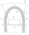
- FIG. 1 is an explanatory view showing a configuration of a sonar device 20 for a ship equipped with a sound transmitting member.
- the sound transmission member according to the present invention is used, for example, to form the sound transmission region ⁇ of the sonar device 20.
- the sonar device 20 is disposed at the front end of a sonar device support (not shown) provided in the hull of the ship, and is always in the water.
- the sonar device 20 includes a transducer 24 and an acoustic window 26.
- the transmitter / receiver 24 is mounted on a frame 28 made of FRP (Fiber Reinforced Plastics) supported inside the acoustic window 26, and is disposed toward the front of the ship.
- FRP Fiber Reinforced Plastics
- the acoustic window 26 protects the transducer 24 and is provided so as to cover the transducer 24, and the interior of the acoustic window 26 is filled with water.
- the acoustic window 26 includes a cylindrical portion 26A and a curved surface portion 26B formed with a convex curved surface at the front portion of the cylindrical portion 26A.
- the frame 28 on which the transducer 24 is mounted is supported inside the cylindrical portion 26A.
- the acoustic window 26 has a sound transmission region ⁇ that allows sound transmission and a sound insulation region ⁇ that blocks sound.
- the curved surface portion 26B of the acoustic window 26 constituting the acoustic transmission region ⁇ is configured by the acoustic transmission member according to the present invention.
- the cylindrical portion 26A of the acoustic window 26 constituting the sound insulation region ⁇ is made of a sound insulation material for sound insulation (including reduction of vibration noise).
- the sound transmission region ⁇ is the entire curved surface portion 26B excluding the end portion near the cylindrical portion 26A, and the range ⁇ shown in FIG. 1 is a front obstacle such as a whale or driftwood. This is a range in which the object is searched by the transducer 24.
- FIG. 2 is an explanatory diagram illustrating a configuration of the sound transmissive member 10 according to the first embodiment.
- the sound transmitting member 10 is illustrated in a planar shape for convenience of description, but the sound transmitting member 10 can be formed according to the application.
- the sound transmission member 10 according to the first embodiment is a planar sound transmission member having sound transmission.
- the sound transmission member 10 has a transmission frequency band from a low frequency region of 100 kHz or less to a limit frequency fm.
- the limit frequency fm is the upper limit frequency of the transmission frequency band of the sound transmission member 10.
- a protective layer may be further provided on the surface of the skin layers 102A and 102B, that is, on the surface opposite to the side of the two skin layers 102A and 102B laminated on the core layers 106A and 106B. This protective layer is provided, for example, to protect the sonar device 20 from an external load or to avoid marine organisms.
- Skin layers 102A and 102B and intermediate layer 104 are formed of a material having a higher elastic modulus than core layers 106A and 106B.
- Skin layers 102A and 102B and intermediate layer 104 are made of a material having an elastic modulus of 100 MPa to 350 GPa, for example. This is because a material having an elastic modulus of less than 100 MPa is difficult to maintain as a structure, and a material having an elastic modulus of more than 350 GPa is too high in acoustic impedance.
- the skin layers 102A and 102B and the intermediate layer 104 are made of, for example, fiber reinforced plastic (FRP (Fiber Reinforced Plastics), specifically GFRP (Glass Fiber Reinforced Plastics), CFRP (Carbon fiber Reinforced Plastics, etc.). It can be formed of either plastic or metal (copper, titanium, etc.).
- FRP Fiber Reinforced Plastics
- GFRP Glass Fiber Reinforced Plastics
- CFRP Carbon fiber Reinforced Plastics, etc.
- the core layers 106A and 106B are formed of a viscoelastic material such as rubber or polyurethane or plastic, for example.
- the core layers 106A and 106B may be formed to have a predetermined density and elastic modulus by injecting glass microballoons into the viscoelastic body or plastic.
- the difference between the acoustic impedance of the material forming the core layers 106A and 106B and the acoustic impedance of the fluid (water or seawater in the present embodiment) surrounding the acoustically transmissive member 10 is the difference between the core layers 106A and 106B. It is desirable that the acoustic impedance of the material to be formed be 50% or less.
- the acoustic impedance is given by the product ⁇ c of the material density ⁇ and the longitudinal wave speed of sound c. That is, the acoustic impedance of the material forming the core layers 106A and 106B is the product ⁇ 1c1 of the density ⁇ 1 of the material forming the core layers 106A and 106B and the longitudinal wave sound velocity c1 in the material forming the core layers 106A and 106B. Given in. Further, the acoustic impedance of the fluid surrounding the acoustically permeable member 10 is given by the density ⁇ 2 of the fluid surrounding the acoustically permeable member 10 and the product ⁇ 2c2 of the longitudinal wave sound velocity c2 in the fluid.
- the core layer is formed so that the difference between the acoustic impedance ⁇ 1c1 of the material forming the core layers 106A and 106B and the acoustic impedance ⁇ 2c2 of the fluid surrounding the acoustically transparent member 10 is 50% or less of the acoustic impedance ⁇ 1c1. It is desirable to adjust the density and elastic modulus of 106A and 106B.
- the thickness of the intermediate layer 104 is 0.2 to 3 times the thickness of the skin layers 102A and 102B, and the thickness of the intermediate layer 104 and the skin layers 102A and 102B is preferably 0.1 mm or more. . This is because the performance of the sound transmitting member 10 can be improved by reducing (for example, making equal) the thickness difference between the intermediate layer 104 and the skin layers 102A and 102B, as will be described later. Further, the thickness dc of the core layer is expressed by the following equations (3) and (4) with respect to the limit frequency fm which is the maximum frequency in the transmission frequency band of the sound transmitting member 10 and the wavelength ⁇ m of the sound wave at the limit frequency fm. Try to meet.
- FIG. 3 is a graph showing the sound transmission characteristics of the sound transmission member 10 of FIG.
- the thickness of the skin layers 102A and 102B is 1.0 mm
- the thickness of the intermediate layer 104 is 2.0 mm
- the thicknesses of the core layers 106A and 106B are 10.5 mm, 9.0 mm, and 7.0 mm. , 5.0 mm, 3.0 mm, and 1.0 mm are plotted for sound transmission characteristics.
- the vertical axis represents transmission loss (dB)
- the horizontal axis represents frequency (kHz). That is, each sound transmitting member 10 has a property of transmitting sound in a frequency band with a small transmission loss and blocking sound in a frequency band with a large transmission loss.
- each sound transmission member 10 has a small transmission loss in the low frequency region, and the value of the transmission loss periodically changes in the high frequency region.
- the upper limit frequency of a band in which the transmission loss is 3 dB or less continuously from the low frequency region where the transmission loss is almost 0 is “limit frequency fm”
- the limit frequency fm is decreased as the core layers 106A and 106B are thinner.
- the region where the transmission loss is small is expanding.
- FIG. 4 is a graph showing the relationship between the ratio of the wavelength ⁇ m of the sound wave at the core layer thickness dc and the limit frequency fm and the limit frequency fm.
- the following formulas (3) and (4) are derived from the graph of FIG.
- FIGS. 5 and 6 show the sound transmission characteristics when the thicknesses of the skin layers 102A, 102B and the intermediate layer 104 are equal (for example, 1.0 mm) and the relationship between the core layer thickness dc and the limit frequency fm. Show.
- the way of viewing the graphs of FIGS. 5 and 6 is the same as that of FIGS. 3 and 4.
- the coefficients in the above formulas (3) and (4) change, and the following formulas (1) and (2) are obtained.
- FIG. 7 is a graph comparing the sound transmission characteristics of the sound transmission member 10 and members having other configurations.
- the graph of FIG. 7A shows the sound transmission characteristics of each member shown in FIG. 7B.
- both sides of the core layer made of rubber are sandwiched by the skin layer made of CFRP, and the thickness of the skin layer is 1.5 mm. Is 11 mm.
- the double sandwich structure shown in (2) of FIG. 7B is the same structure as the sound transmitting member 10 according to the present embodiment shown in FIG. 2, and is a skin layer formed of CFRP and a core formed of rubber.
- a layer, an intermediate layer made of CFRP, a core layer made of rubber, and a skin layer made of CFRP are laminated in this order.
- the thickness of the skin layer is 1.0 mm, the thickness of the core layer is 10.5 mm, and the thickness of the intermediate layer is 2.0 mm.
- (3) in FIG. 7B is a modification of the thickness of each layer of the double sandwich structure shown in (2).
- the thickness of the skin layer is 1.0 mm, the thickness of the core layer is 2 mm, The thickness is 1.0 mm.
- (4) in FIG. 7B is a CFRP single plate, the same thickness (3 mm) as the sum of the thicknesses of the skin layer and intermediate layer (part formed of CFRP) of the double sandwich structure shown in (3). ).
- the maximum value of the transmission loss in the high-frequency region is larger in (2), but near the minimum value of the transmission loss.
- the bandwidth in (2) is larger than that in (1). More specifically, for example, when a range from a value at which transmission loss is minimized to +0.5 dB is evaluated as a band where good sound transmission characteristics can be obtained, (1) has a wider bandwidth in the band near 100 kHz. However, in the frequency bands higher than that (160 kHz, 230 kHz, 300 kHz), the bandwidth of (2) is wider, and it can be seen that good sound transmission characteristics can be obtained even in the high frequency region.
- (3) has a limit frequency fm exceeding 200 kHz, and has better sound transmission than other structures.
- the band where the characteristics can be obtained is widened.
- the two core layers 106A and 106B that are the damping layers are provided, so that vibration is hardly excited. For this reason, while reducing the noise by the vibration of the own ship, etc., the noise by the surrounding fluid can be suppressed, and the accuracy of the search by the sonar device 20 can be improved.
- the sound transmission member 10 can form a sound transmission region (window region) continuous up to the high frequency region, the influence of the characteristic change due to the manufacturing variation, temperature, etc. in the individual sound transmission members 10 is affected. Good sound transmission characteristics can be obtained without receiving. Moreover, since the manufacturing dispersion
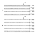
- FIG. 8 is an explanatory diagram illustrating a configuration of the sound transmissive members 30 and 40 according to the second embodiment.
- a skin layer 302A, a core layer 306A, an intermediate layer 304A, a core layer 306B, an intermediate layer 304B, a core layer 306C, and a skin layer 302B are stacked in this order from the upper side in FIG. 8A.
- the skin layer 402A, the core layer 406A, the intermediate layer 404A, the core layer 406B, the intermediate layer 404B, the core layer 406C, the intermediate layer 404C, the core layer 406D, and the skin layer 402B are stacked in this order from the upper side in FIG. 8B. Has been.
- each layer is the same as in the first embodiment, and the skin layers 302A, 302B, 402A, 402B and the intermediate layers 304A, 304B, 404A-404C are more elastic than the core layers 306A-306C, 406A-406D.
- Made of high rate material it is assumed that the skin layers 302A, 302B, 402A, 402B and the intermediate layers 304A, 304B, 404A-404C are made of CFRP, and the core layers 306A-306C, 406A-406D are made of rubber.
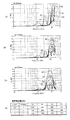
- FIGS. 9 to 11 are graphs showing the sound transmission characteristics of the sound transmission members 30 and 40.
- FIG. 9 to 11 show the sound transmission characteristics of other members shown in FIG. 12 in addition to the sound transmission members 30 and 40 for comparison.
- (5) of FIG. 12 is the sound transmission member 30, and (6) of FIG.
- the sound transmission characteristics shown in FIGS. 9 to 11 are calculated by changing the thicknesses of the skin layer, the intermediate layer, and the core layer of the sound transmission members 30 and 40.
- the skin layer and the intermediate layer have the same thickness ts, and the thickness of the core layer is tc.
- the sandwich structure shown in FIG. 12 (1) has a core layer made of rubber sandwiched on both sides of a skin layer made of CFRP, and the thickness of the skin layer is 1.5 mm.
- the thickness is 5 mm.
- the double sandwich structure shown in (2) of FIG. 12 is formed of a skin layer formed of CFRP, a core layer formed of rubber, an intermediate layer formed of CFRP, a core layer formed of rubber, and CFRP.
- the skin layers are stacked in this order.
- the thickness of the skin layer is 1.0 mm
- the thickness of the core layer is 5.0 mm
- the thickness of the intermediate layer is 2.0 mm.
- (3) in FIG. 12 is obtained by changing the thickness of the sandwich structure shown in FIG. 12 (1), where the thickness of the skin layer is ts and the thickness of the core layer is tc.
- (4) in FIG. 12 is obtained by changing the thickness of the double sandwich structure shown in FIG. 12 (2).
- the thickness of the skin layer and the intermediate layer is ts
- the thickness of the core layer is tc. To do.
- FIG. 9A to 9C shows the changed results.
- FIG. 9D shows the limit frequency fm (the upper limit frequency of the band where the transmission loss is 3 dB or less continuously from the low frequency region) in each of the members (3) to (6).
- the limit frequency fm increases as the core layer thickness tc decreases. Further, as the number of intermediate layers and core layers increases, the maximum value of the transmission loss in the high frequency region becomes larger than the limit frequency fm. On the other hand, the limit frequency fm does not change greatly even if the number of intermediate layers and core layers changes.
- FIGS. 10A to 10C show the results of changing the thickness ts of the core layer to 1 mm and changing the thickness ts of the skin layer and the intermediate layer to 0.5 mm, 1.0 mm, and 2.0 mm, respectively.
- FIG. 10D shows the limit frequency fm in each of the members (3) to (6).
- the limit frequency fm increases as the thickness ts of the skin layer and the intermediate layer decreases. Further, as the number of intermediate layers and core layers increases, the maximum value of the transmission loss in the high frequency region becomes larger than the limit frequency fm. On the other hand, the limit frequency fm does not change greatly even if the number of intermediate layers and core layers changes.
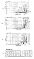
- FIGS. 11A to 11C show the results of changing the thickness ts of the skin layer and the intermediate layer and the thickness tc of the core layer equally to 0.5 mm, 0.75 mm, and 1.0 mm, respectively.
- FIG. 11D shows the limit frequency fm in each of the members (3) to (6). In FIGS. 11A to 11C, the limit frequency fm is higher as the thickness ts of the skin layer and the intermediate layer and the thickness tc of the core layer are thinner.
- the thickness ts of the skin layer and the intermediate layer and the thickness tc of the core layer are reduced. Can be seen to be effective. Further, it can be seen from FIGS. 9 to 11 that the limit frequency fm changes little due to the difference in the number of intermediate layers and core layers. Therefore, it can be said that the number of laminated layers of the intermediate layer and the core layer can be arbitrarily set according to the strength requirement for the sound transmitting member 10.
- the thickness of the skin layer, the intermediate layer, and the core layer is thin enough to satisfy the limit frequency required for the sound transmissive member. Then, by adjusting the number of laminated layers of the intermediate layer and the core layer so as to satisfy the strength required for the sound transmissive member, a sound transmissive member having an arbitrary characteristic can be obtained.
- 10, 30, 40 ... sound transmissive member 102A, 102B, 302A, 302B, 402A, 402B ... skin layer, 104, 304A, 304B, 404A, 404B, 404C ... intermediate layer, 106A, 106B, 306A, 306B, 306C, 406A, 406B, 406C, 406D: Core layer.
Landscapes
- Engineering & Computer Science (AREA)
- Physics & Mathematics (AREA)
- Radar, Positioning & Navigation (AREA)
- Remote Sensing (AREA)
- Mechanical Engineering (AREA)
- Computer Networks & Wireless Communication (AREA)
- General Physics & Mathematics (AREA)
- Acoustics & Sound (AREA)
- Chemical & Material Sciences (AREA)
- Combustion & Propulsion (AREA)
- Signal Processing (AREA)
- Ocean & Marine Engineering (AREA)
- Laminated Bodies (AREA)
- Soundproofing, Sound Blocking, And Sound Damping (AREA)
- Measurement Of Velocity Or Position Using Acoustic Or Ultrasonic Waves (AREA)
Abstract
Description
図13は、従来技術にかかる音響透過性部材の構造を示す説明図である。図13に示す音響透過性部材130は、コア層1302に厚さ5mmの天然ゴム、スキン層1304に厚さ2mmのCFRP(Carbon fiber Reinforced Plastics)を用いている。
この構造によれば、従来の音響透過性部材において音響透過性を得られる低周波領域に加えて、下記式(5)および(6)を満足する周波数fを透過する音響透過性部材を形成することができる。下記式(5)および(6)において、dcはコア層1302の厚さ、Cはコア層1302における音速、C0は外囲流体における音速である。

図14において、縦軸は透過損失ILであり、横軸は周波数を示す。グラフ中、符号1402は図13に示す音響透過性部材の水温20℃の水中における音響透過特性を実測した実測値である。また、符号1404は符号1402に示す実測値から水温20℃の水中における音響透過特性をモデル化した計算値、符号1406は符号1404に示す計算値に基づいて水温16℃の水中における音響透過特性を計算した計算値である。
請求項2の発明にかかる音響透過性部材は、前記音響透過性部材が、所定の音響周波数帯を透過周波数帯とし、前記コア層の厚さdcは、前記透過周波数帯の最大周波数fmおよび前記最大周波数fmにおける音波の波長λmに対して、下記式(1)および(2)を満たす、ことを特徴とする。

請求項4の発明にかかる音響透過性部材は、前記スキン層および前記中間層が、弾性率が100MPa以上350GPa以下の素材で形成されている、ことを特徴とする。
請求項5の発明にかかる音響透過性部材は、前記スキン層および前記中間層が、繊維強化プラスチック、プラスチック、金属のいずか1つで形成されている、ことを特徴とする。
請求項6の発明にかかる音響透過性部材は、前記コア層が、粘弾性体またはプラスチックで形成されている、ことを特徴とする。
請求項7の発明にかかる音響透過性部材は、前記コア層が、前記粘弾性体または前記プラスチック内にガラスマイクロバルーンが注入され、密度および弾性率が所定の値に形成されている、ことを特徴とする。
請求項8の発明にかかる音響透過性部材は、前記コア層を形成する素材の音響インピーダンスと、前記音響透過性部材を外囲する流体の音響インピーダンスとの差が前記コア層を形成する素材の音響インピーダンスの50%以下である、ことを特徴とする。
請求項9の発明にかかる音響透過性部材は、2層の前記スキン層の前記コア層に積層される側と反対側の表面に、保護層が設けられている、ことを特徴とする。
請求項2の発明によれば、高周波領域まで連続した音響透過領域(窓領域)を形成することができるので、個々の音響透過性部材における製造バラツキや温度等の影響による特性変化の影響を受けることなく、良好な音響透過特性を得ることができる。また、上記のように個々の音響透過性部材10における製造バラツキを許容することができるため、製造時における歩留まりを向上させることができる。
請求項3の発明によれば、中間層およびスキン層の厚さを0.1mm以上とすることによって、音響透過性部材の強度を確保することができる。また、中間層およびスキン層の厚さの差を小さくする(たとえば等しくする)ことによって、音響透過性部材の性能を向上させることができる。
請求項4の発明によれば、スキン層および中間層を様々な素材で形成することができる。
請求項5の発明によれば、音響透過性部材の強度を確保しつつ、優れた音響透過特性を得ることができる。
請求項6の発明によれば、音響透過性部材の強度を確保しつつ、優れた音響透過特性を得ることができる。
請求項7の発明によれば、コア層を任意の密度および弾性率で形成することができる。
請求項8の発明によれば、境界面での反射を低減し、音響透過特性を向上させることができる。
請求項9の発明によれば、保護層により外囲流体からの圧力や海洋生物の影響を低減させ、音響透過性部材の強度を向上させることができる。
図1は、音響透過性部材を搭載した船舶用のソーナー装置20の構成を示す説明図である。本発明にかかる音響透過性部材は、たとえばソーナー装置20の音響透過領域αを形成するために用いられる。
ソーナー装置20は、船舶の船体に設けられたソーナー装置支持台(図示なし)の前端に配置され、常時水中に位置している。
ソーナー装置20は、送受波器24と音響窓26とを含んで構成されている。
送受波器24は、音響窓26の内部に支持されたFRP(Fiber Reinforced Plastics)製のフレーム28に搭載され、船舶の前方に向けて配置されている。
音響窓26は、円筒部26Aと、円筒部26Aの先部に前方に凸状の曲面で形成された曲面部26Bとを有している。
送受波器24が搭載されたフレーム28は、円筒部26Aの内部で支持されている。
音響透過領域αを構成する音響窓26の曲面部26Bは、本発明にかかる音響透過性部材で構成されている。
また、遮音領域βを構成する音響窓26の円筒部26Aは、音響を遮音する(振動雑音の低減を含む)遮音材で構成されている。このような遮音材として、気泡(ガラスマイクロバルーン)を混在させたゴムやポリウレタンなどの粘弾性体(気泡分散型遮音材)や、あるいは、小孔が多数貫設された薄肉のゴム板の両面を薄肉のゴム板で挟んだもの(気孔型遮音材)など、従来公知の様々な材料が使用可能である。
本実施の形態では、音響透過領域αは、円筒部26A寄りの端部を除いた曲面部26Bの全域となっており、図1に示す範囲θが、クジラや流木などのような前方の障害物を送受波器24により探索する範囲となっている。
図2は、実施の形態1にかかる音響透過性部材10の構成を示す説明図である。
以下の説明では、説明の便宜上、音響透過性部材10を平面状に図示しているが、音響透過性部材10は、用途に応じて成形可能である。
実施の形態1にかかる音響透過性部材10は、音響透過性を有する面状の音響透過性部材である。音響透過性部材10は、100kHz以下の低周波領域から限界周波数fmまでの透過周波数帯を有する。限界周波数fmとは、音響透過性部材10の透過周波数帯の上限周波数である。
音響透過性部材10は、2層のスキン層102A,102Bの間に、1層の中間層104と、2層のコア層106A,106Bとが交互に積層されている(N=1)。より詳細には、図2の上部側から順に、スキン層102A、コア層106A、中間層104、コア層106B、スキン層102Bが積層されている。
なお、スキン層102A,102Bの表面、すなわち2層のスキン層102A,102Bのコア層106A,106Bに積層される側と反対側の表面に、さらに保護層が設けられていてもよい。この保護層は、たとえば外部からの荷重からソーナー装置20を保護したり、海洋生物忌避のために設けられる。
スキン層102A,102Bと中間層104とは、コア層106A,106Bよりも弾性率が高い素材で形成されている。
スキン層102A,102Bおよび中間層104は、たとえば弾性率が100MPa以上350GPa以下の素材で形成されている。これは、弾性率が100MPa未満の素材では構造体として維持するのが困難となり、弾性率350GPaを超える素材では音響インピーダンスが高くなりすぎるためである。
スキン層102A,102Bおよび中間層104は、具体的には、たとえば繊維強化プラスチック(FRP(Fiber Reinforced Plastics)、具体的にはGFRP(Glass fiber Reinforced Plastics)、CFRP(Carbon fiber Reinforced Plastics)など)、プラスチック、金属(銅、チタンなど)のいずかで形成することができる。
なお、コア層106A,106Bは、上記粘弾性体またはプラスチック内にガラスマイクロバルーンが注入され、密度および弾性率が所定の値に形成されていてもよい。
また、コア層106A,106Bを形成する素材の音響インピーダンスと、音響透過性部材10を外囲する流体(本実施の形態では水または海水)の音響インピーダンスとの差は、コア層106A,106Bを形成する素材の音響インピーダンスの50%以下とすることが望ましい。
ここで、音響インピーダンスは、物質の密度ρと縦波音速cの積ρcで与えられる。すなわち、コア層106A,106Bを形成する素材の音響インピーダンスは、コア層106A,106Bを形成する素材の密度ρ1と、コア層106A,106Bを形成する素材中の縦波音速c1との積ρ1c1とで与えられる。また、音響透過性部材10を外囲する流体の音響インピーダンスは、音響透過性部材10を外囲する流体の密度ρ2と、同流体中の縦波音速c2の積ρ2c2とで与えられる。
そして、コア層106A,106Bを形成する素材の音響インピーダンスρ1c1と、音響透過性部材10を外囲する流体の音響インピーダンスρ2c2との差が、音響インピーダンスρ1c1の50%以下となるように、コア層106A,106Bの密度および弾性率を調整することが望ましい。
これは、コア層106A,106Bを形成する素材の音響インピーダンスρ1c1と、音響透過性部材10を外囲する流体の音響インピーダンスρ2c2との差が大きいと、境界面での反射が大きくなり、音響透過性が低下するためである。
中間層104の厚さは、スキン層102A,102Bの厚さの0.2倍以上3倍以下であり、中間層104およびスキン層102A,102Bの厚さは0.1mm以上とすることが望ましい。これは、後述するように中間層104およびスキン層102A,102Bの厚さの差を小さくする(たとえば等しくする)ことによって、音響透過性部材10の性能を向上させることができるためである。
また、コア層の厚さdcは、音響透過性部材10の透過周波数帯の最大周波数である限界周波数fmおよび限界周波数fmにおける音波の波長λmに対して、下記式(3)および(4)を満たすようにする。

図3には、スキン層102A,102Bの厚さを1.0mm、中間層104の厚さを2.0mmとして、コア層106A,106Bの厚さを10.5mm、9.0mm、7.0mm、5.0mm、3.0mm、1.0mmにそれぞれ変更した場合の音響透過特性がプロットされている。
図3のグラフにおいて、縦軸は透過損失(dB)であり、横軸は周波数(kHz)である。すなわち、それぞれの音響透過性部材10は、透過損失が小さい周波数帯の音響を透過させ、透過損失が大きい周波数帯の音響を遮断する性質を有する。
図3に示すように、それぞれの音響透過性部材10は、低周波領域で透過損失が小さく、高周波領域では透過損失の値が周期的に変化している。ここで、透過損失がほぼ0の低周波領域から連続して透過損失が3dB以下である帯域の上限周波数を「限界周波数fm」とすると、コア層106A,106Bの厚さが薄いほど限界周波数fmが上昇し、透過損失が小さい領域が拡大している。
図4のグラフから、下記式(3)および(4)が導かれる。

スキン層102A,102Bと中間層104との厚さを等しくした場合には、上記式(3)および(4)における係数が変わり、下記式(1)および(2)のようになる。

図7Aのグラフは、図7Bに示す各部材の音響透過特性を示している。図7Bの(1)に示すサンドイッチ構造は、ゴムで形成されたコア層の両面を、CFRPで形成されたスキン層ではさんでおり、スキン層の厚さは1.5mm、コア層の厚さは11mmである。
図7Bの(2)に示す二重サンドイッチ構造は、図2に示す本実施の形態にかかる音響透過性部材10と同様の構造であり、CFRPで形成されたスキン層、ゴムで形成されたコア層、CFRPで形成された中間層、ゴムで形成されたコア層、CFRPで形成されたスキン層の順に積層されている。スキン層の厚さは1.0mm、コア層の厚さは10.5mm、中間層の厚さは2.0mmである。
図7Bの(3)は、(2)に示す二重サンドイッチ構造の各層の厚さを変更したものであり、スキン層の厚さは1.0mm、コア層の厚さは2mm、中間層の厚さは1.0mmである。
図7Bの(4)は、CFRP単体の板であり、(3)に示す二重サンドイッチ構造のスキン層および中間層(CFRPで形成された部分)の厚さの総和と同一の厚さ(3mm)を有する。
また、上記のように個々の音響透過性部材10における製造バラツキを許容することができるため、製造時における歩留まりを向上させることができる。
また、コア層106A,106Bを薄く形成することにより、音響透過性部材10の軽量化を図ることができるとともに、製造コストを低減することができる。
実施の形態1では、2層のスキン層の間に、1層の中間層と、2層のコア層とが交互に積層するようにした(N=1)。
実施の形態2では、中間層とコア層の積層層数を増加させ、2層のスキン層の間に、N層の中間層と、N+1層のコア層とを交互に積層することとする(N≧2)。
図8は、実施の形態2にかかる音響透過性部材30,40の構成を示す説明図である。
図8Aに示す音響透過性部材30は、2層のスキン層302A,302Bの間に、2層の中間層304A,304Bと、3層のコア層306A,306B,306Cとが交互に積層されている(N=2)。より詳細には、図8Aの上部側から順に、スキン層302A、コア層306A、中間層304A、コア層306B、中間層304B、コア層306C、スキン層302Bが積層されている。
また、図8Bに示す音響透過性部材40は、2層のスキン層402A,402Bの間に、3層の中間層404A,404B,404Cと、4層のコア層406A,406B,406C,406Dとが交互に積層されている(N=3)。より詳細には、図8Bの上部側から順に、スキン層402A、コア層406A、中間層404A、コア層406B、中間層404B、コア層406C、中間層404C、コア層406D、スキン層402Bが積層されている。
以下では、スキン層302A,302B,402A,402Bおよび中間層304A,304B,404A~404CはCFRPで、コア層306A~306C,406A~406Dはゴムで形成されているものとする。
図9~図11は、音響透過性部材30,40の他に、図12に示す他の部材の音響透過特性も比較のために示している。
図12の(5)は音響透過性部材30であり、図12の(6)は音響透過性部材40である。図9~図11に示す音響透過特性は、音響透過性部材30,40のスキン層、中間層、およびコア層の厚さを変更して計算をおこなったものである。図9~図11では、スキン層および中間層を同一の厚さtsとし、コア層の厚さをtcとしている。
また、図12の(1)に示すサンドイッチ構造は、ゴムで形成されたコア層の両面を、CFRPで形成されたスキン層ではさんでおり、スキン層の厚さは1.5mm、コア層の厚さは5mmである。
図12の(2)に示す二重サンドイッチ構造は、CFRPで形成されたスキン層、ゴムで形成されたコア層、CFRPで形成された中間層、ゴムで形成されたコア層、CFRPで形成されたスキン層の順に積層されている。スキン層の厚さは1.0mm、コア層の厚さは5.0mm、中間層の厚さは2.0mmである。
また、図12の(3)は、図12(1)に示すサンドイッチ構造の厚さを変更したものであり、スキン層の厚さをts、コア層の厚さをtcとする。
また、図12の(4)は、図12(2)に示す二重サンドイッチ構造の厚さを変更したものであり、スキン層および中間層の厚さをts、コア層の厚さをtcとする。
図9A~図9Cでは、コア層の厚さtcが薄いほど限界周波数fmが高くなる。また、中間層およびコア層の層数が増加するほど、限界周波数fmより高周波領域における透過損失の極大値は大きくなる。一方、限界周波数fmについては、中間層およびコア層の層数が変化しても大きな変化はない。
図10A~図10Cにおいても、スキン層および中間層の厚さtsが薄いほど限界周波数fmが高くなる。また、中間層およびコア層の層数が増加するほど、限界周波数fmより高周波領域における透過損失の極大値は大きくなる。一方、限界周波数fmについては、中間層およびコア層の層数が変化しても大きな変化はない。
図11A~図11Cにおいて、スキン層および中間層の厚さtsとコア層の厚さtcとが薄いほど限界周波数fmが高くなっている。
また、図9~図11から、限界周波数fmの値は、中間層およびコア層の層数の違いによる変化は小さいことがわかる。よって、中間層およびコア層の積層層数は、音響透過性部材10への強度要求に応じて任意に設定することが可能であるといえる。
Claims (9)
- 音響透過性を有する面状の音響透過性部材であって、
2層のスキン層の間に、N+1層のコア層と、N層の中間層とが交互に積層されており、
前記スキン層と前記中間層とが、前記コア層よりも弾性率が高い素材で形成されている、
ことを特徴とする音響透過性部材。 - 前記音響透過性部材は、所定の音響周波数帯を透過周波数帯とし、
前記コア層の厚さdcは、前記透過周波数帯の最大周波数fmおよび前記最大周波数fmにおける音波の波長λmに対して、下記式(1)および(2)を満たす、
ことを特徴とする請求項1記載の音響透過性部材。

- 前記中間層の厚さは、前記スキン層の厚さの0.2倍以上3倍以下であり、
前記中間層および前記スキン層の厚さは0.1mm以上である、
ことを特徴とする請求項1または2記載の音響透過性部材。 - 前記スキン層および前記中間層は、弾性率が100MPa以上350GPa以下の素材で形成されている、
ことを特徴とする請求項1から3のいずれか1項記載の音響透過性部材。 - 前記スキン層および前記中間層は、繊維強化プラスチック、プラスチック、金属のいずれか1つで形成されている、
ことを特徴とする請求項1から4のいずれか1項記載の音響透過性部材。 - 前記コア層は、粘弾性体またはプラスチックで形成されている、
ことを特徴とする請求項1から5のいずれか1項記載の音響透過性部材。 - 前記コア層は、前記粘弾性体または前記プラスチック内にガラスマイクロバルーンが注入され、密度および弾性率が所定の値に形成されている、
ことを特徴とする請求項6記載の音響透過性部材。 - 前記コア層を形成する素材の音響インピーダンスと、前記音響透過性部材を外囲する流体の音響インピーダンスとの差が前記コア層を形成する素材の音響インピーダンスの50%以下である、
ことを特徴とする請求項1から7のいずれか1項記載の音響透過性部材。 - 2層の前記スキン層の前記コア層に積層される側と反対側の表面に、保護層が設けられている、
ことを特徴とする請求項1から8のいずれか1項記載の音響透過性部材。
Priority Applications (3)
| Application Number | Priority Date | Filing Date | Title |
|---|---|---|---|
| AU2014347864A AU2014347864B2 (en) | 2013-11-18 | 2014-11-11 | Sound-transmitting member |
| EP14861647.7A EP3073762A4 (en) | 2013-11-18 | 2014-11-11 | Sound-transmitting member |
| US15/037,593 US20160299220A1 (en) | 2013-11-18 | 2014-11-11 | Sound-Transmitting Member |
Applications Claiming Priority (2)
| Application Number | Priority Date | Filing Date | Title |
|---|---|---|---|
| JP2013237556A JP6179365B2 (ja) | 2013-11-18 | 2013-11-18 | 音響透過性部材 |
| JP2013-237556 | 2013-11-18 |
Publications (1)
| Publication Number | Publication Date |
|---|---|
| WO2015072455A1 true WO2015072455A1 (ja) | 2015-05-21 |
Family
ID=53057389
Family Applications (1)
| Application Number | Title | Priority Date | Filing Date |
|---|---|---|---|
| PCT/JP2014/079853 WO2015072455A1 (ja) | 2013-11-18 | 2014-11-11 | 音響透過性部材 |
Country Status (5)
| Country | Link |
|---|---|
| US (1) | US20160299220A1 (ja) |
| EP (1) | EP3073762A4 (ja) |
| JP (1) | JP6179365B2 (ja) |
| AU (1) | AU2014347864B2 (ja) |
| WO (1) | WO2015072455A1 (ja) |
Cited By (2)
| Publication number | Priority date | Publication date | Assignee | Title |
|---|---|---|---|---|
| EP3434466A4 (en) * | 2016-03-23 | 2019-11-20 | The Yokohama Rubber Co., Ltd. | ACOUSTIC TRANSPARENT ELEMENT AND METHOD FOR CONSTRUCTING THEREOF |
| CN114536896A (zh) * | 2022-02-25 | 2022-05-27 | 江苏科技大学 | 一种船用导流透声罩基材制备工艺 |
Families Citing this family (2)
| Publication number | Priority date | Publication date | Assignee | Title |
|---|---|---|---|---|
| CN106739190B (zh) * | 2016-11-24 | 2019-10-29 | 株洲时代新材料科技股份有限公司 | 一种轻质多层复合隔音隔热材料及其制备方法 |
| CN107234839B (zh) * | 2017-07-23 | 2024-01-09 | 咸宁海威复合材料制品有限公司 | 船用声呐导流罩的复合料板及制备方法 |
Citations (6)
| Publication number | Priority date | Publication date | Assignee | Title |
|---|---|---|---|---|
| JPS6114391U (ja) * | 1984-06-28 | 1986-01-28 | 古野電気株式会社 | 超音波送受波器用ド−ム |
| JPH01126578A (ja) * | 1987-11-10 | 1989-05-18 | Nec Corp | ソーナードーム |
| JPH02254387A (ja) * | 1989-03-29 | 1990-10-15 | Tech Res & Dev Inst Of Japan Def Agency | 木集成型ソーナードーム |
| US4997705A (en) | 1986-05-21 | 1991-03-05 | The B. F. Goodrich Company | Window for acoustic wave form and method for making |
| JPH0450683A (ja) * | 1990-06-20 | 1992-02-19 | B F Goodrich Co:The | 音波形のための窓及びその製造方法 |
| JP2012154791A (ja) * | 2011-01-26 | 2012-08-16 | Yokohama Rubber Co Ltd:The | 船舶用ソナードームおよび船舶用ソナー装置 |
Family Cites Families (4)
| Publication number | Priority date | Publication date | Assignee | Title |
|---|---|---|---|---|
| US3330376A (en) * | 1965-06-11 | 1967-07-11 | Lord Corp | Structure acoustically transparent for compressional waves and acoustically damped for bending or flexural waves |
| DE3642747A1 (de) * | 1986-12-15 | 1988-06-16 | Krupp Atlas Elektronik Gmbh | Huellkoerper fuer eine hydrophonanordnung |
| US4923757A (en) * | 1987-12-16 | 1990-05-08 | Ppg Industries, Inc. | Bilayer windshield with an abrasion and solvent resistant polyurethane protective coating |
| US6831876B1 (en) * | 2003-07-09 | 2004-12-14 | Goodrich Corporation | Acoustic window |
-
2013
- 2013-11-18 JP JP2013237556A patent/JP6179365B2/ja active Active
-
2014
- 2014-11-11 AU AU2014347864A patent/AU2014347864B2/en active Active
- 2014-11-11 WO PCT/JP2014/079853 patent/WO2015072455A1/ja active Application Filing
- 2014-11-11 EP EP14861647.7A patent/EP3073762A4/en active Pending
- 2014-11-11 US US15/037,593 patent/US20160299220A1/en not_active Abandoned
Patent Citations (6)
| Publication number | Priority date | Publication date | Assignee | Title |
|---|---|---|---|---|
| JPS6114391U (ja) * | 1984-06-28 | 1986-01-28 | 古野電気株式会社 | 超音波送受波器用ド−ム |
| US4997705A (en) | 1986-05-21 | 1991-03-05 | The B. F. Goodrich Company | Window for acoustic wave form and method for making |
| JPH01126578A (ja) * | 1987-11-10 | 1989-05-18 | Nec Corp | ソーナードーム |
| JPH02254387A (ja) * | 1989-03-29 | 1990-10-15 | Tech Res & Dev Inst Of Japan Def Agency | 木集成型ソーナードーム |
| JPH0450683A (ja) * | 1990-06-20 | 1992-02-19 | B F Goodrich Co:The | 音波形のための窓及びその製造方法 |
| JP2012154791A (ja) * | 2011-01-26 | 2012-08-16 | Yokohama Rubber Co Ltd:The | 船舶用ソナードームおよび船舶用ソナー装置 |
Non-Patent Citations (2)
| Title |
|---|
| See also references of EP3073762A4 |
| TOSHIYUKI NAKANISHI: "An acoustic window with low transmission loss made of three polymer plastic layers", JOURNAL OF THE ACOUSTICAL SOCIETY OF JAPAN, vol. 46, no. 3, 1 March 1990 (1990-03-01), pages 205 - 211, XP008183212 * |
Cited By (4)
| Publication number | Priority date | Publication date | Assignee | Title |
|---|---|---|---|---|
| EP3434466A4 (en) * | 2016-03-23 | 2019-11-20 | The Yokohama Rubber Co., Ltd. | ACOUSTIC TRANSPARENT ELEMENT AND METHOD FOR CONSTRUCTING THEREOF |
| AU2017237772B2 (en) * | 2016-03-23 | 2020-04-23 | The Yokohama Rubber Co., Ltd. | Acoustically transparent member and method for designing same |
| US11064292B2 (en) | 2016-03-23 | 2021-07-13 | The Yokohama Rubber Co., Ltd. | Acoustic transmission member and method of designing same |
| CN114536896A (zh) * | 2022-02-25 | 2022-05-27 | 江苏科技大学 | 一种船用导流透声罩基材制备工艺 |
Also Published As
| Publication number | Publication date |
|---|---|
| JP2015098086A (ja) | 2015-05-28 |
| US20160299220A1 (en) | 2016-10-13 |
| AU2014347864B2 (en) | 2017-04-13 |
| JP6179365B2 (ja) | 2017-08-16 |
| EP3073762A1 (en) | 2016-09-28 |
| AU2014347864A1 (en) | 2016-06-02 |
| EP3073762A4 (en) | 2017-07-26 |
Similar Documents
| Publication | Publication Date | Title |
|---|---|---|
| WO2017163804A1 (ja) | 音響透過性部材およびその設計方法 | |
| Sharma et al. | Acoustic performance of gratings of cylindrical voids in a soft elastic medium with a steel backing | |
| CN106042468B (zh) | 一种宽频隔音蜂窝板 | |
| Liu | Sound transmission through triple-panel structures lined with poroelastic materials | |
| Wen et al. | Effects of locally resonant modes on underwater sound absorption in viscoelastic materials | |
| WO2015072455A1 (ja) | 音響透過性部材 | |
| Zhou et al. | Extending and lowering band gaps by multilayered locally resonant phononic crystals | |
| CN103996396A (zh) | 一种轻质二组元软性薄层局域共振声学材料结构 | |
| Jiang et al. | Multiple low-frequency broad band gaps generated by a phononic crystal of periodic circular cavity sandwich plates | |
| Nguyen et al. | A broadband acoustic panel based on double-layer membrane-type metamaterials | |
| CN106570203B (zh) | 基于声子晶体理论的超声刀的刀杆结构确定方法 | |
| Zhao et al. | Acoustic absorption of a metamaterial panel: Mechanism, boundary effect and experimental demonstration | |
| CN216388742U (zh) | 声学隔离面板和包括声学隔离面板的组件 | |
| US8717848B2 (en) | Ultrasound probe | |
| CN110880312A (zh) | 一种水下亚波长局域共振型声学超材料 | |
| Chen et al. | Bandwidth broadening for transmission loss of acoustic waves using coupled membrane-ring structure | |
| Yilmaz et al. | Dynamics of locally resonant and inertially amplified lattice materials | |
| EP2960900B1 (en) | Systems and methods for acoustic windows | |
| Chen et al. | Large band gaps of petal-shaped acoustic metamaterials based on local resonance | |
| CN115910016B (zh) | 一种基于空腔谐振的水下吸声覆盖层 | |
| Hsu | Low-frequency forbidden bands in phononic crystal plates with Helmholtz resonators | |
| Krynkin et al. | Sonic crystal noise barriers made of resonant elements | |
| Aberkane-Gauthier et al. | Soft solid subwavelength plates with periodic inclusions: Effects on acoustic Transmission Loss | |
| Wang et al. | Metasurface by multiple perforated panels in a coiled arrangement | |
| Wang et al. | Acoustically soft and mechanically robust hierarchical metamaterials in water |
Legal Events
| Date | Code | Title | Description |
|---|---|---|---|
| 121 | Ep: the epo has been informed by wipo that ep was designated in this application |
Ref document number: 14861647 Country of ref document: EP Kind code of ref document: A1 |
|
| NENP | Non-entry into the national phase |
Ref country code: DE |
|
| WWE | Wipo information: entry into national phase |
Ref document number: 15037593 Country of ref document: US |
|
| ENP | Entry into the national phase |
Ref document number: 2014347864 Country of ref document: AU Date of ref document: 20141111 Kind code of ref document: A |
|
| REEP | Request for entry into the european phase |
Ref document number: 2014861647 Country of ref document: EP |
|
| WWE | Wipo information: entry into national phase |
Ref document number: 2014861647 Country of ref document: EP |