EP3073762A1 - Sound-transmitting member - Google Patents
Sound-transmitting member Download PDFInfo
- Publication number
- EP3073762A1 EP3073762A1 EP14861647.7A EP14861647A EP3073762A1 EP 3073762 A1 EP3073762 A1 EP 3073762A1 EP 14861647 A EP14861647 A EP 14861647A EP 3073762 A1 EP3073762 A1 EP 3073762A1
- Authority
- EP
- European Patent Office
- Prior art keywords
- sound
- layers
- transmitting member
- transmitting
- core
- Prior art date
- Legal status (The legal status is an assumption and is not a legal conclusion. Google has not performed a legal analysis and makes no representation as to the accuracy of the status listed.)
- Pending
Links
- 239000010410 layer Substances 0.000 claims abstract description 163
- 239000012792 core layer Substances 0.000 claims abstract description 104
- 239000000463 material Substances 0.000 claims abstract description 27
- 230000005540 biological transmission Effects 0.000 claims description 27
- 239000012530 fluid Substances 0.000 claims description 13
- 229920003023 plastic Polymers 0.000 claims description 9
- 239000004033 plastic Substances 0.000 claims description 9
- 229920002430 Fibre-reinforced plastic Polymers 0.000 claims description 6
- 239000011151 fibre-reinforced plastic Substances 0.000 claims description 6
- 239000011241 protective layer Substances 0.000 claims description 5
- 239000011521 glass Substances 0.000 claims description 4
- 229910052751 metal Inorganic materials 0.000 claims description 3
- 239000002184 metal Substances 0.000 claims description 3
- 239000004918 carbon fiber reinforced polymer Substances 0.000 abstract description 18
- 229920001971 elastomer Polymers 0.000 abstract description 17
- 239000005060 rubber Substances 0.000 abstract description 17
- 238000004519 manufacturing process Methods 0.000 description 7
- XLYOFNOQVPJJNP-UHFFFAOYSA-N water Substances O XLYOFNOQVPJJNP-UHFFFAOYSA-N 0.000 description 6
- 230000010355 oscillation Effects 0.000 description 5
- 238000005516 engineering process Methods 0.000 description 4
- 230000000694 effects Effects 0.000 description 3
- 238000013016 damping Methods 0.000 description 2
- 239000011152 fibreglass Substances 0.000 description 2
- 239000011810 insulating material Substances 0.000 description 2
- 238000009413 insulation Methods 0.000 description 2
- 239000004814 polyurethane Substances 0.000 description 2
- 229920002635 polyurethane Polymers 0.000 description 2
- -1 specifically Substances 0.000 description 2
- 241000283153 Cetacea Species 0.000 description 1
- RYGMFSIKBFXOCR-UHFFFAOYSA-N Copper Chemical compound [Cu] RYGMFSIKBFXOCR-UHFFFAOYSA-N 0.000 description 1
- JOYRKODLDBILNP-UHFFFAOYSA-N Ethyl urethane Chemical compound CCOC(N)=O JOYRKODLDBILNP-UHFFFAOYSA-N 0.000 description 1
- 244000043261 Hevea brasiliensis Species 0.000 description 1
- 229910000831 Steel Inorganic materials 0.000 description 1
- RTAQQCXQSZGOHL-UHFFFAOYSA-N Titanium Chemical compound [Ti] RTAQQCXQSZGOHL-UHFFFAOYSA-N 0.000 description 1
- 229910052802 copper Inorganic materials 0.000 description 1
- 239000010949 copper Substances 0.000 description 1
- 239000013505 freshwater Substances 0.000 description 1
- 230000000116 mitigating effect Effects 0.000 description 1
- 229920003052 natural elastomer Polymers 0.000 description 1
- 229920001194 natural rubber Polymers 0.000 description 1
- 239000013535 sea water Substances 0.000 description 1
- 239000002356 single layer Substances 0.000 description 1
- 239000010959 steel Substances 0.000 description 1
- 230000001629 suppression Effects 0.000 description 1
- 239000010936 titanium Substances 0.000 description 1
- 229910052719 titanium Inorganic materials 0.000 description 1
Images


Classifications
-
- G—PHYSICS
- G01—MEASURING; TESTING
- G01S—RADIO DIRECTION-FINDING; RADIO NAVIGATION; DETERMINING DISTANCE OR VELOCITY BY USE OF RADIO WAVES; LOCATING OR PRESENCE-DETECTING BY USE OF THE REFLECTION OR RERADIATION OF RADIO WAVES; ANALOGOUS ARRANGEMENTS USING OTHER WAVES
- G01S7/00—Details of systems according to groups G01S13/00, G01S15/00, G01S17/00
- G01S7/52—Details of systems according to groups G01S13/00, G01S15/00, G01S17/00 of systems according to group G01S15/00
- G01S7/521—Constructional features
-
- B—PERFORMING OPERATIONS; TRANSPORTING
- B32—LAYERED PRODUCTS
- B32B—LAYERED PRODUCTS, i.e. PRODUCTS BUILT-UP OF STRATA OF FLAT OR NON-FLAT, e.g. CELLULAR OR HONEYCOMB, FORM
- B32B25/00—Layered products comprising a layer of natural or synthetic rubber
- B32B25/04—Layered products comprising a layer of natural or synthetic rubber comprising rubber as the main or only constituent of a layer, which is next to another layer of the same or of a different material
- B32B25/08—Layered products comprising a layer of natural or synthetic rubber comprising rubber as the main or only constituent of a layer, which is next to another layer of the same or of a different material of synthetic resin
-
- B—PERFORMING OPERATIONS; TRANSPORTING
- B32—LAYERED PRODUCTS
- B32B—LAYERED PRODUCTS, i.e. PRODUCTS BUILT-UP OF STRATA OF FLAT OR NON-FLAT, e.g. CELLULAR OR HONEYCOMB, FORM
- B32B27/00—Layered products comprising a layer of synthetic resin
- B32B27/18—Layered products comprising a layer of synthetic resin characterised by the use of special additives
- B32B27/20—Layered products comprising a layer of synthetic resin characterised by the use of special additives using fillers, pigments, thixotroping agents
-
- B—PERFORMING OPERATIONS; TRANSPORTING
- B32—LAYERED PRODUCTS
- B32B—LAYERED PRODUCTS, i.e. PRODUCTS BUILT-UP OF STRATA OF FLAT OR NON-FLAT, e.g. CELLULAR OR HONEYCOMB, FORM
- B32B7/00—Layered products characterised by the relation between layers; Layered products characterised by the relative orientation of features between layers, or by the relative values of a measurable parameter between layers, i.e. products comprising layers having different physical, chemical or physicochemical properties; Layered products characterised by the interconnection of layers
- B32B7/02—Physical, chemical or physicochemical properties
- B32B7/022—Mechanical properties
-
- B—PERFORMING OPERATIONS; TRANSPORTING
- B63—SHIPS OR OTHER WATERBORNE VESSELS; RELATED EQUIPMENT
- B63B—SHIPS OR OTHER WATERBORNE VESSELS; EQUIPMENT FOR SHIPPING
- B63B49/00—Arrangements of nautical instruments or navigational aids
-
- H—ELECTRICITY
- H04—ELECTRIC COMMUNICATION TECHNIQUE
- H04R—LOUDSPEAKERS, MICROPHONES, GRAMOPHONE PICK-UPS OR LIKE ACOUSTIC ELECTROMECHANICAL TRANSDUCERS; DEAF-AID SETS; PUBLIC ADDRESS SYSTEMS
- H04R1/00—Details of transducers, loudspeakers or microphones
- H04R1/44—Special adaptations for subaqueous use, e.g. for hydrophone
-
- B—PERFORMING OPERATIONS; TRANSPORTING
- B32—LAYERED PRODUCTS
- B32B—LAYERED PRODUCTS, i.e. PRODUCTS BUILT-UP OF STRATA OF FLAT OR NON-FLAT, e.g. CELLULAR OR HONEYCOMB, FORM
- B32B2250/00—Layers arrangement
- B32B2250/05—5 or more layers
-
- B—PERFORMING OPERATIONS; TRANSPORTING
- B32—LAYERED PRODUCTS
- B32B—LAYERED PRODUCTS, i.e. PRODUCTS BUILT-UP OF STRATA OF FLAT OR NON-FLAT, e.g. CELLULAR OR HONEYCOMB, FORM
- B32B2262/00—Composition or structural features of fibres which form a fibrous or filamentary layer or are present as additives
- B32B2262/10—Inorganic fibres
- B32B2262/106—Carbon fibres, e.g. graphite fibres
-
- B—PERFORMING OPERATIONS; TRANSPORTING
- B32—LAYERED PRODUCTS
- B32B—LAYERED PRODUCTS, i.e. PRODUCTS BUILT-UP OF STRATA OF FLAT OR NON-FLAT, e.g. CELLULAR OR HONEYCOMB, FORM
- B32B2307/00—Properties of the layers or laminate
- B32B2307/10—Properties of the layers or laminate having particular acoustical properties
-
- B—PERFORMING OPERATIONS; TRANSPORTING
- B32—LAYERED PRODUCTS
- B32B—LAYERED PRODUCTS, i.e. PRODUCTS BUILT-UP OF STRATA OF FLAT OR NON-FLAT, e.g. CELLULAR OR HONEYCOMB, FORM
- B32B2307/00—Properties of the layers or laminate
- B32B2307/50—Properties of the layers or laminate having particular mechanical properties
- B32B2307/51—Elastic
-
- B—PERFORMING OPERATIONS; TRANSPORTING
- B32—LAYERED PRODUCTS
- B32B—LAYERED PRODUCTS, i.e. PRODUCTS BUILT-UP OF STRATA OF FLAT OR NON-FLAT, e.g. CELLULAR OR HONEYCOMB, FORM
- B32B2605/00—Vehicles
- B32B2605/12—Ships
-
- B—PERFORMING OPERATIONS; TRANSPORTING
- B63—SHIPS OR OTHER WATERBORNE VESSELS; RELATED EQUIPMENT
- B63B—SHIPS OR OTHER WATERBORNE VESSELS; EQUIPMENT FOR SHIPPING
- B63B2201/00—Signalling devices
- B63B2201/18—Sonar
-
- H—ELECTRICITY
- H04—ELECTRIC COMMUNICATION TECHNIQUE
- H04R—LOUDSPEAKERS, MICROPHONES, GRAMOPHONE PICK-UPS OR LIKE ACOUSTIC ELECTROMECHANICAL TRANSDUCERS; DEAF-AID SETS; PUBLIC ADDRESS SYSTEMS
- H04R1/00—Details of transducers, loudspeakers or microphones
- H04R1/02—Casings; Cabinets ; Supports therefor; Mountings therein
- H04R1/026—Supports for loudspeaker casings
-
- H—ELECTRICITY
- H04—ELECTRIC COMMUNICATION TECHNIQUE
- H04R—LOUDSPEAKERS, MICROPHONES, GRAMOPHONE PICK-UPS OR LIKE ACOUSTIC ELECTROMECHANICAL TRANSDUCERS; DEAF-AID SETS; PUBLIC ADDRESS SYSTEMS
- H04R1/00—Details of transducers, loudspeakers or microphones
- H04R1/02—Casings; Cabinets ; Supports therefor; Mountings therein
- H04R1/028—Casings; Cabinets ; Supports therefor; Mountings therein associated with devices performing functions other than acoustics, e.g. electric candles
Definitions
- an object of the present invention is to provide a sound-transmitting member in which a wide sound-transmitting band can be attained in a high frequency region.
- a plurality of core layers which are damping layers are provided, which suppresses oscillation, thereby enabling a reduction in noise due to, for example, oscillation in a device or the like in which the sound-transmitting member is used, and a suppression of noise in the surrounding fluid. Therefore, it is possible to improve the performance of a device or the like that uses the sound-transmitting member.
- FIG. 4 is a graph showing the relationship between the ratio of the thickness dc of the core layer to a wavelength ⁇ m of a sound wave at the threshold frequency fm, and the threshold frequency fm.
- the following formulae (3) and (4) are derived from the graph of FIG. 4 .
- FIGS. 5 and 6 show the relationships between the sound-transmitting characteristics and thickness dc of the core layer, and between the sound-transmitting properties and the threshold frequency fm, respectively, for when the skin layers 102A and 102B are equal in thickness to the intermediate layer 104 (1.0 mm, for example).
- the graphs of FIGS. 5 and 6 are to be interpreted similarly to FIGS. 3 and 4 . If the skin layers 102A and 102B are equal in thickness to the intermediate layer 104, the coefficients of formulae (3) and (4) are changed to those of formulae (1) and (2).
- the sound-transmitting member 10 of the first embodiment there are two core layers 106A and 106B, which are damping layers, which inhibits oscillation. This enables reduction in noise generated by, for example, oscillation of the ship, and mitigation of noise from the surrounding fluid, which allows for improvements in search accuracy by the sonar device 20.
- the sound-transmitting member 10 can form a sound-transmitting region (window region) that is continuous with the high frequency region, which allows for excellent sound-transmitting characteristics to be attained without being affected by changes in characteristics due to manufacturing variations of individual sound-transmitting members 10, temperature, or the like. Because manufacturing variations of individual sound-transmitting members 10 can be taken into account as described above, manufacturing yield can be improved. Forming the core layers 106A and 106B to be thin makes it possible to reduce the weight of the sound-transmitting member 10 and to reduce the manufacturing cost.
- the materials forming the respective layers are similar to those of the first embodiment, and the skin layers 302A, 302B, 402A, and 402B and the intermediate layers 304A, 304B, and 404A to 404C are formed of a material having a higher elastic modulus than the core layers 306A to 306C and 406A to 406D.
- the skin layers 302A, 302B, 402A, and 402B and the intermediate layers 304A, 304B, and 404A to 404C are formed of CFRP
- the core layers 306A to 306C and 406A to 406D are formed of rubber.
- FIGS. 9A to 11D are graphs showing sound-transmitting characteristics of the sound-transmitting members 30 and 40.
- FIGS. 9A to 11D show sound-transmitting characteristics of other members illustrated in FIG. 12 besides the sound-transmitting members 30 and 40 for comparison.
- (5) is the sound-transmitting member 30, and (6) is the sound-transmitting member 40.
- the sound-transmitting characteristics shown in FIGS. 9A to 11D were calculated while changing the thicknesses of the skin layers, intermediate layers, and core layers of the sound-transmitting members 30 and 40.
- the skin layers and the intermediate layers have the same thickness ts
- the core layers have a thickness tc.
- the core layer formed of rubber is sandwiched between skin layers formed of CFRP from both surfaces of the core layer, and the thickness of the skin layers is 1.5 mm and the thickness of the core layer is 5 mm.
- the skin layer formed of CFRP, the core layer formed of rubber, the intermediate layer formed of CFRP, the core layer formed of rubber, and the skin layer formed of CFRP are stacked in the stated order.
- the skin layers are 1.0 mm in thickness
- the core layers are 5.0 mm in thickness
- the intermediate layer is 2.0 mm in thickness.
- the thickness of the sandwich structure is changed from that illustrated in (1) of FIG.
- the thickness of the sandwich structure is changed from that illustrated in (2) of FIG. 12 , with the skin layers and the intermediate layers having a thickness ts, and the core layers having a thickness tc.
- FIGS. 9A to 9C show results of changing the thickness tc of the core layers to 0.5 mm ( FIG. 9A ), 1.0 mm ( FIG. 9B ), and 2.0 mm ( FIG. 9C ), with the thickness ts of the skin layers and intermediate layers being fixed to 1 mm.
- FIG. 9D shows the threshold frequencies fm in the respective members (3) to (6) (upper limit frequencies of a band where the transmission loss is continuously 3 dB or less from a low frequency region).
- the threshold frequencies fm in the respective members (3) to (6) (upper limit frequencies of a band where the transmission loss is continuously 3 dB or less from a low frequency region).
- FIGS. 10A to 10C illustrate results of changing the thickness ts of the skin layers and intermediate layers to 0.5 mm, 1.0 mm, and 2.0 mm, with the thickness tc of the core layers being fixed to 1 mm.
- FIG. 10D shows the threshold frequencies fm of the respective members (3) to (6).
- the threshold frequencies fm the less the thickness ts of the skin layers and intermediate layers is, the higher the threshold frequency fm is.
- the threshold frequency fm does not undergo major change even if the number of intermediate layers and core layers changes.
- FIGS. 11A to 11C show results of changing the thickness ts of the skin layers and intermediate layers and the thickness tc of the core layers equally to 0.5 mm, 0.75 mm, and 1.0 mm.
- FIG. 11D shows the threshold frequencies fm of the respective members (3) to (6). In FIGS. 11A to 11C , the less the thickness ts of the skin layers and intermediate layers and the thickness tc of the core layers are, the higher the threshold frequency fm is.
- FIGS. 9A to 11D it can be seen that reducing the thickness ts of the skin layers and the intermediate layers and the thickness tc of the core layers is effective in expanding the region where the transmission loss is low in the low frequency region and increasing the threshold frequency fm. Also, based on FIGS. 9A to 11D , it can be seen that there is little change in the value of the threshold frequency fm resulting from a change in the number of intermediate layers and core layers. Therefore, the number of intermediate layers and core layers can be set to any number according to strength requirements of the sound-transmitting member 10.
- the sound-transmitting members 30 and 40 of the second embodiment it is possible to attain a sound-transmitting member with desired characteristics by adjusting the number of intermediate layers and core layers according to the strength required of the sound-transmitting member, upon reducing the thicknesses of the skin layers, intermediate layers, and core layers to a degree that the threshold frequency required of the sound-transmitting member is satisfied.
Landscapes
- Engineering & Computer Science (AREA)
- Physics & Mathematics (AREA)
- Radar, Positioning & Navigation (AREA)
- Remote Sensing (AREA)
- Mechanical Engineering (AREA)
- Computer Networks & Wireless Communication (AREA)
- General Physics & Mathematics (AREA)
- Acoustics & Sound (AREA)
- Chemical & Material Sciences (AREA)
- Combustion & Propulsion (AREA)
- Signal Processing (AREA)
- Ocean & Marine Engineering (AREA)
- Laminated Bodies (AREA)
- Soundproofing, Sound Blocking, And Sound Damping (AREA)
- Measurement Of Velocity Or Position Using Acoustic Or Ultrasonic Waves (AREA)
Abstract
Description
- The present invention relates to a sound-transmitting member having sound-transmitting properties.
- Conventionally, sound-transmitting members having sound-transmitting properties have been used for a sound-transmitting region of a device such as a marine sonar. A member formed of steel is a typical example of a conventional sound-transmitting member, but rubber sound-transmitting members such as rubber domes or rubber windows are known as an improved structure for the conventional sound-transmitting members. Such conventional sound-transmitting members are essentially single-layer structures with excellent sound-transmitting characteristics in the low frequency region of a few kHz or less, but are difficult to use in a high frequency band of 20 kHz or greater.
- In
Patent Document 1 below, a sound-transmitting member that employs a sandwich structure in which both surfaces of a core layer are covered by skin layers is disclosed.
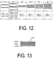
FIG. 13 is an explanatory drawing illustrating a structure of a sound-transmitting member according to a conventional technology. In a sound-transmittingmember 130 illustrated inFIG. 13 , natural rubber having a thickness of 5 mm is used for the core layer 1302, and carbon fiber reinforced plastics (CFRP) having a thickness of 2 mm is used for theskin layers 1304.
According to this structure, it is possible to form a sound-transmitting member that transmits, in addition to frequencies of the low frequency region where conventional sound-transmitting members can attain sound-transmitting properties, a frequency f that satisfies formulae (5) and (6) below. In formulae (5) and (6) below, dc denotes the thickness of the core layer 1302, C denotes the sound velocity in the core layer 1302, and C0 denotes the sound velocity in a surrounding fluid.
[Formula 1]

- Patent Document 1:
US Patent No. 4997705B - A viscoelastic member such as rubber or urethane is used for the core layer of the conventional structure illustrated in
FIG. 13 . Such a viscoelastic member has temperature characteristics, and depending on the change in temperature, the sound velocity in the viscoelastic member (C in the above-described formula (5)) also changes. The sound velocity in the surrounding fluid (C0 in the above-described formula (5)) also changes depending on the temperature. As a result, the frequency f indicated in the above-described formula (6) shifts due to the temperature, resulting in a large impact on system performance. -
FIG. 14 is a graph showing transmission characteristics of the sound-transmitting member illustrated inFIG. 13 . InFIG. 14 , the vertical axis indicates transmission loss IL, and the horizontal axis indicates frequency. In the graph, thereference sign 1402 indicates values attained by actually measuring sound-transmitting characteristics of the sound-transmitting member illustrated inFIG. 13 in 20°C water. Thereference sign 1404 indicates calculated values attained by modeling sound-transmitting characteristics in 20°C water according to the actually measured values indicated by thereference sign 1402, and thereference sign 1406 indicates values attained by calculating the sound-transmitting characteristics in 16°C water on the basis of the calculated values indicated by thereference sign 1404. - It is estimated that a temperature change by 4°C from 20°C to 16°C causes the sound velocity to change by 15%, and as a result, it is estimated that a window region of a high frequency region shifts by 15% as indicated by the
reference signs FIG. 14 is 0.6 dB (1 dB or less) at a water temperature of 20°C, but increases to 3.5 dB at a water temperature of 16°C. - Accordingly, the conventional technology is capable of expanding the transmission bandwidth in the sound-transmitting member, but cannot attain a practically sufficient bandwidth in the high frequency region.
- In light of the above-described problem of the conventional technology, an object of the present invention is to provide a sound-transmitting member in which a wide sound-transmitting band can be attained in a high frequency region.
- In order to solve the above-mentioned problem and achieve the object of the present invention, a sound-transmitting member according to the invention described in
claim 1 of the present invention having a planar shape and having sound-transmitting properties includes two skin layers, N + 1 core layers, and N intermediate layers. In such a sound-transmitting member, the core layer and the intermediate layer are alternately stacked between the skin layers, and the skin layer and the intermediate layer are formed of a material having a higher elastic modulus than the core layers. In the sound-transmitting member according to the invention described inclaim 2, a prescribed sound frequency band is set as a transmission frequency band, and a thickness dc of the core layers satisfies the following formulae (1) and (2) with respect to a maximum frequency fm of the transmission frequency band and a wavelength λm of a sound wave at the maximum frequency fm.
[Formula 2]

- In the sound-transmitting member according to the invention described in
claim 3, a thickness of the intermediate layer is a multiple of from 0.2 to 3, both inclusive, of a thickness of the skin layers, and the thicknesses of the intermediate layer and the skin layers are 0.1 mm or greater.
In the sound-transmitting member according to the invention described inclaim 4, the skin layers and the intermediate layer are formed of a material having an elastic modulus of from 100 MPa to 350 GPa, both inclusive.
In the sound-transmitting member according to the invention described inclaim 5, the skin layers and the intermediate layer are formed of any one of fiber reinforced plastic, plastic, and metal.
In the sound-transmitting member according to the invention described inclaim 6, the core layers are formed of a viscoelastic member or plastic.
In the sound-transmitting member according to the invention described inclaim 7, the core layers are formed of the viscoelastic member or the plastic into which the glass microballoons are mixed such that a density and elastic modulus thereof are at prescribed values.
In the sound-transmitting member according to the invention described in claim 8, a difference between a sound impedance of a material forming the core layers and a sound impedance of a fluid surrounding the sound-transmitting member is 50% or less of the sound impedance of the material forming the core layers.
In the sound-transmitting member according to the invention described inclaim 9, protective layers are formed on surfaces of the two skin layers, the surfaces being opposite to surfaces of the skin layers facing the core layers. - According to the invention described in
claim 1, a plurality of core layers which are damping layers are provided, which suppresses oscillation, thereby enabling a reduction in noise due to, for example, oscillation in a device or the like in which the sound-transmitting member is used, and a suppression of noise in the surrounding fluid. Therefore, it is possible to improve the performance of a device or the like that uses the sound-transmitting member. - According to the invention described in
claim 2, it is possible to form a sound-transmitting region (window region) that is continuous with the high frequency region, which allows for excellent sound-transmitting characteristics to be attained without being affected by changes in characteristics due to manufacturing variations of individual sound-transmitting members, temperature, and the like. Because manufacturing variation of individual sound-transmittingmembers 10 can be taken into account, manufacturing yield can be improved. - According to the invention described in
claim 3, setting the thicknesses of the intermediate layer and the skin layer to 0.1 mm or greater makes it possible to ensure the strength of the sound-transmitting member. Also, making the difference in thickness between the intermediate layer and the skin layers small (or equal, for example) allows the performance of the sound-transmitting member to be improved. - According to the invention described in
claim 4, it is possible to form the skin layer and the intermediate layer of various materials. - According to the invention described in
claim 5, it is possible to attain excellent sound-transmitting characteristics while ensuring strength of the sound-transmitting member. - According to the invention described in
claim 6, it is possible to attain excellent sound-transmitting characteristics while ensuring strength of the sound-transmitting member. - According to the invention described in
claim 7, it is possible to form the core layer having any density and elastic modulus. - According to the invention described in claim 8, it is possible to reduce reflection at the boundary and improve sound-transmitting characteristics. According to the invention described in
claim 9, it is possible to use the protective layer to reduce the effect of pressure from the surrounding fluid and the effect of marine organisms, and improve the strength of the sound-transmitting member. -
- FIG. 1
- is an explanatory drawing illustrating a configuration of a
marine sonar device 20 equipped with a sound-transmitting member. - FIG. 2
- is an explanatory drawing illustrating a configuration of a sound-transmitting
member 10 according to the first embodiment. - FIG. 3
- is a graph showing sound-transmitting characteristics of the sound-transmitting
member 10 illustrated inFIG. 2 . - FIG. 4
- is a graph showing the relationship between the ratio of the thickness dc of a core layer to a wavelength λm of a sound wave at a threshold frequency fm, and the threshold frequency fm.
- FIG. 5
- is a graph showing the sound-transmitting characteristics for when the thicknesses of the skin layer and the intermediate layer are equal.
- FIG. 6
- is a graph showing the relationship between the thickness dc of the core layer and the threshold frequency fm for when the thicknesses of the skin layer and the intermediate layer are equal.
- FIGS. 7A and 7B
- show a graph of a comparison of sound-transmitting characteristics between the sound-transmitting
member 10 and members having other configurations. - FIGS. 8A
- and 8B are explanatory drawings illustrating configurations of sound-transmitting
members - FIGS. 9A to 9D
- are graphs showing sound-transmitting characteristics of the sound-transmitting
members - FIGS. 10A to 10D
- are graphs showing sound-transmitting characteristics of the sound-transmitting
members - FIGS. 11A to 11D
- are graphs showing sound-transmitting characteristics of the sound-transmitting
members - FIG. 12
- is an explanatory drawing illustrating structures of other sound-transmitting members.
- FIG. 13
- is an explanatory drawing illustrating a structure of a sound-transmitting member according to a conventional technology.
- FIG. 14
- is a graph showing transmission characteristics of the sound-transmitting member illustrated in
FIG. 13 . - Preferred embodiments of a sound-transmitting member according to the present invention are described below in detail with reference to the attached drawings.
-
FIG. 1 is an explanatory drawing illustrating a configuration of amarine sonar device 20 equipped with a sound-transmitting member. The sound-transmitting member according to the present invention is used in order to form a sound-transmitting region α in thesonar device 20, for example. Thesonar device 20 is disposed at a leading end of a sonar device support platform (not illustrated) provided in the body of a ship.
Thesonar device 20 includes atransducer 24 and anacoustic window 26.
Thetransducer 24 is mounted on aframe 28 made of fiber reinforced plastics (FRP) supported on the inside of theacoustic window 26, and is disposed towards the front of the ship. - The
acoustic window 26 is intended for protecting thetransducer 24 and is provided so as to cover thetransducer 24, with water filling the inside of theacoustic window 26.
Theacoustic window 26 has acylindrical portion 26A, and acurved surface portion 26B that is formed in a curved shape that protrudes toward the front from the tip of thecylindrical portion 26A.
Theframe 28 on which thetransducer 24 is mounted is supported on the inside of thecylindrical portion 26A. - The
acoustic window 26 has the sound-transmitting region α that enables sound-transmitting, and a sound insulation region β that blocks sound.
Thecurved surface portion 26B of theacoustic window 26 that constitutes the sound-transmitting region α is made of the sound-transmitting member according to the present invention.
Thecylindrical portion 26A of theacoustic window 26 constituting the sound insulation region β is constituted of a sound insulating member that blocks sound (including a reduction in oscillation noise). As such a sound insulating member, various conventionally known materials can be used such as a viscoelastic member (sound insulating material with scattered air bubbles) such as rubber or polyurethane with air bubbles (glass microballoons) mixed in, or a material in which a thin rubber plate with many small holes provided therethrough is sandwiched between thin rubber plates (air hole-type sound insulating material) from both surfaces of the thin rubber plate with many small holes provided therethrough.
In the present embodiment, the sound-transmitting region α is the entirety of thecurved surface portion 26B excluding edge portions of thecurved surface portion 26B that are located near thecylindrical portion 26A, and a range θ illustrated inFIG. 1 is the range in which thetransducer 24 searches for obstacles in the front such as whales and driftwood. - Next, the sound-transmitting member constituting the sound-transmitting region α will be described.
FIG. 2 is an explanatory drawing illustrating a configuration of a sound-transmittingmember 10 according to the first embodiment.
In the description below, for ease of explanation, the sound-transmittingmember 10 is illustrated as having a planar shape, but the sound-transmittingmember 10 can be molded in any shape depending on the application.
The sound-transmittingmember 10 according to the first embodiment has a planar shape with sound-transmitting properties. The sound-transmittingmember 10 has a transmission frequency band from a low frequency region of 100 kHz or less to a threshold frequency fm. The threshold frequency fm is the upper limit frequency in the transmission frequency band of the sound-transmittingmember 10.
The sound-transmittingmember 10 includes twoskin layers intermediate layer 104, and twocore layers FIG. 2 : theskin layer 102A, thecore layer 106A, theintermediate layer 104, thecore layer 106B, and theskin layer 102B.
Protective layers may further be provided on the surfaces of the skin layers 102A and 102B, that is, the surfaces of the twoskin layers sonar device 20 from external loads or from marine organisms, for example. - Next, the materials of the respective layers will be described.
The skin layers 102A and 102B and theintermediate layer 104 are formed of a material with a higher elastic modulus than the core layers 106A and 106B.
The skin layers 102A and 102B and theintermediate layer 104 are formed of a material with an elastic modulus of from 100 MPa to 350 GPa, both inclusive, for example. This is because the material having an elastic modulus of less than 100 MPa makes it difficult to maintain the layers as structural members, and the material having an elastic modulus of greater than 350 GPa has too high of a sound impedance.
The skin layers 102A and 102B and theintermediate layer 104 can specifically be formed of fiber reinforced plastics (FRP, specifically, glass fiber reinforced plastics (GFRP), carbon fiber reinforced plastics (CFRP), or the like), plastic, or metal (copper, titanium, or the like). - Also, the core layers 106A and 106B are formed of a viscoelastic member such as rubber or polyurethane, or plastic, for example.
The core layers 106A and 106B may be formed of the above-described viscoelastic member or plastic into which glass microballoons are mixed such that the density and elastic modulus thereof are at a prescribed value. It is preferable that the difference in sound impedance between the material forming the core layers 106A and 106B, and the fluid (fresh water or seawater in the present embodiment) surrounding the sound-transmittingmember 10 be 50% or less of the sound impedance of the material forming the core layers 106A and 106B.
The sound impedance is calculated as the product pc of a material density ρ and a longitudinal wave sound velocity c. In other words, the sound impedance of the material forming the core layers 106A and 106B is calculated as a product p1c1 of a density ρ1 of the material forming the core layers 106A and 106B, and the longitudinal wave sound velocity c1 in the material forming the core layers 106A and 106B. The sound impedance of the fluid surrounding the sound-transmittingmember 10 is calculated as a product ρ2c2 of a density ρ2 of the fluid surrounding the sound-transmittingmember 10 and the longitudinal wave sound velocity c2 in the same fluid.
It is preferable that the density and elastic modulus of the core layers 106A and 106B be adjusted such that the difference between the sound impedance ρ1c1 of the material forming the core layers 106A and 106B, and the sound impedance p2c2 of the fluid surrounding the sound-transmittingmember 10 is 50% or less of the sound impedance ρ1c1.
This is because if the difference between the sound impedance p1c1 of the material forming the core layers 106A and 106B and the sound impedance p2c2 of the fluid surrounding the sound-transmittingmember 10 is too great, the boundary becomes highly reflective, reducing the sound-transmitting properties. - Next, the thicknesses of the respective layers will be described.
It is preferable that the thickness of theintermediate layer 104 be a multiple of from 0.2 to 3, both inclusive, of the thickness of the skin layers 102A and 102B, and that the thickness ofintermediate layer 104 and the skin layers 102A and 10B be 0.1 mm or greater. This is because, as described below, forming theintermediate layer 104 and the skin layers 102A and 102B such that the difference in thickness thereof is small (equal thickness, for example) enables improvement in performance of the sound-transmittingmember 10.
The thickness dc of the core layer satisfies the following formulae (3) and (4) in relation to the threshold frequency fm, which is the maximum frequency of the transmission frequency band of the sound-transmittingmember 10, and the wavelength λm of a sound wave at the threshold frequency fm.
[Formula 3]

-
FIG. 3 is a graph showing sound-transmitting characteristics of the sound-transmittingmember 10 illustrated inFIG. 2 .
InFIG. 3 , sound-transmitting characteristics are plotted for cases in which the thickness of the core layers 106A and 106B is 10.5 mm, 9.0 mm, 7.0 mm, 5.0 mm, 3.0 mm, and 1.0 mm, where the thickness of the skin layers 102A and 102B is 1.0 mm and the thickness of theintermediate layer 104 is 2.0 mm.
In the graph ofFIG. 3 , the vertical axis indicates transmission loss (dB), and the horizontal axis indicates frequency (kHz). In other words, each of the sound-transmittingmembers 10 has properties by which sounds in a frequency band with a small transmission loss are transmitted, and sounds in a frequency band with a large transmission loss are blocked.
As illustrated inFIG. 3 , in the respective sound-transmittingmembers 10, the transmission loss in the low frequency region is small, and the transmission loss in the high frequency region periodically changes. If the "threshold frequency fm" is defined as the upper limit frequency of a band where the transmission loss changes continuously from substantially 0 dB in a low frequency region to 3 dB or less, then the thinner the core layers 106A and 106B are, the greater the threshold frequency fm is, which expands the range with a low transmission loss. -
FIG. 4 is a graph showing the relationship between the ratio of the thickness dc of the core layer to a wavelength λm of a sound wave at the threshold frequency fm, and the threshold frequency fm.
The following formulae (3) and (4) are derived from the graph ofFIG. 4 .
[Formula 4]

-
FIGS. 5 and6 show the relationships between the sound-transmitting characteristics and thickness dc of the core layer, and between the sound-transmitting properties and the threshold frequency fm, respectively, for when the skin layers 102A and 102B are equal in thickness to the intermediate layer 104 (1.0 mm, for example). The graphs ofFIGS. 5 and6 are to be interpreted similarly toFIGS. 3 and4 .
If the skin layers 102A and 102B are equal in thickness to theintermediate layer 104, the coefficients of formulae (3) and (4) are changed to those of formulae (1) and (2).
[Formula 5]

-
FIGS. 7A and 7B show a graph of a comparison of sound-transmitting characteristics between the sound-transmittingmember 10 and members having other configurations.
The graph ofFIG. 7A indicates the respective sound-transmitting characteristics of the members shown inFIG. 7B . In the sandwich structure illustrated in (1) inFIG. 7B , the core layer formed of rubber is sandwiched between skin layers formed of CFRP from both surfaces of the core layer, and the thickness of the skin layers is 1.5 mm and the thickness of the core layer is 11 mm.
The double-sandwich structure illustrated in (2) ofFIG. 7B is similar to that of the sound-transmittingmember 10 according to the present embodiment illustrated inFIG. 2 , and in this structure, the skin layer formed of CFRP, the core layer formed of rubber, the intermediate layer formed of CFRP, the core layer formed of rubber, and the skin layer formed of CFRP are stacked in the stated order. The skin layers are 1.0 mm in thickness, the core layers are 10.5 mm in thickness, and the intermediate layer is 2.0 mm in thickness.
In (3) ofFIG. 7B , a structure is illustrated in which the respective thicknesses of the layers are changed from those of the double-sandwich structure illustrated in (2), with the skin layers being 1.0 mm in thickness, the core layers being 2 mm in thickness, and the intermediate layer being 1.0 mm in thickness.
A single CFRP plate is illustrated in (4) ofFIG. 7B , and this CFRP plate has the same thickness (3 mm) as the sum of the thicknesses of the skin layers and the intermediate layer (formed of CFRP) of the double-sandwich structure illustrated in (3). - When comparing the sandwich structure illustrated in (1) and the double-sandwich structure illustrated in (2), the maximum transmission loss in the high frequency region is greater in (2), but the bandwidth in the vicinity of the minimum transmission loss is greater in (2) than in (1). More specifically, when evaluating the range from the minimum transmission loss to +0.5 dB as a band where excellent sound-transmitting characteristics can be attained, the bandwidth becomes greater in (1) in the band in the vicinity of 100 kHz, and in greater frequency bands (160 kHz, 230 kHz, 300 kHz), the bandwidth becomes greater in (2), which means excellent sound-transmitting characteristics can be attained even in a high frequency region.
- Also, when comparing the double-sandwich structure illustrated in (3), in which the core layer is made thin, with the structures, the threshold frequency fm in (3) exceeds 200 kHz, which means that the band in which excellent sound-transmitting characteristics can be attained is wider in (3) than in the other structures.
- As described above, according to the sound-transmitting
member 10 of the first embodiment, there are twocore layers sonar device 20. - Also, the sound-transmitting
member 10 can form a sound-transmitting region (window region) that is continuous with the high frequency region, which allows for excellent sound-transmitting characteristics to be attained without being affected by changes in characteristics due to manufacturing variations of individual sound-transmittingmembers 10, temperature, or the like.
Because manufacturing variations of individual sound-transmittingmembers 10 can be taken into account as described above, manufacturing yield can be improved.
Forming the core layers 106A and 106B to be thin makes it possible to reduce the weight of the sound-transmittingmember 10 and to reduce the manufacturing cost. - In the first embodiment, one intermediate layer and two core layers are disposed between the two skin layers, the intermediate layer and the core layer being alternately stacked (N = 1).
In the second embodiment, the number of intermediate layers and core layers is increased, and N intermediate layers and N + 1 core layers are disposed between the two skin layers, the intermediate layer and the core layer being alternately stacked (N ≥ 2).
FIGS. 8A and 8B are explanatory drawings illustrating configurations of sound-transmittingmembers
The sound-transmittingmember 30 illustrated inFIG. 8A includes twoskin layers 302A and 302B, twointermediate layers core layers FIG. 8A : theskin layer 302A, thecore layer 306A, theintermediate layer 304A, thecore layer 306B, theintermediate layer 304B, thecore layer 306C, and the skin layer 302B.
Also, the sound-transmittingmember 40 illustrated inFIG. 8B includes twoskin layers intermediate layers core layers FIG. 8B : theskin layer 402A, thecore layer 406A, theintermediate layer 404A, thecore layer 406B, theintermediate layer 404B, thecore layer 406C, theintermediate layer 404C, thecore layer 406D, and theskin layer 402B. - The materials forming the respective layers are similar to those of the first embodiment, and the skin layers 302A, 302B, 402A, and 402B and the
intermediate layers
In the description below, the skin layers 302A, 302B, 402A, and 402B and theintermediate layers -
FIGS. 9A to 11D are graphs showing sound-transmitting characteristics of the sound-transmittingmembers
FIGS. 9A to 11D show sound-transmitting characteristics of other members illustrated inFIG. 12 besides the sound-transmittingmembers
InFIG. 12 , (5) is the sound-transmittingmember 30, and (6) is the sound-transmittingmember 40. The sound-transmitting characteristics shown inFIGS. 9A to 11D were calculated while changing the thicknesses of the skin layers, intermediate layers, and core layers of the sound-transmittingmembers FIGS. 9A to 11D , the skin layers and the intermediate layers have the same thickness ts, and the core layers have a thickness tc.
In the sandwich structure illustrated in (1) ofFIG. 12 , the core layer formed of rubber is sandwiched between skin layers formed of CFRP from both surfaces of the core layer, and the thickness of the skin layers is 1.5 mm and the thickness of the core layer is 5 mm.
In the double-sandwich structure illustrated in (2) ofFIG. 12 , the skin layer formed of CFRP, the core layer formed of rubber, the intermediate layer formed of CFRP, the core layer formed of rubber, and the skin layer formed of CFRP are stacked in the stated order. The skin layers are 1.0 mm in thickness, the core layers are 5.0 mm in thickness, and the intermediate layer is 2.0 mm in thickness.
In (3) ofFIG. 12 , the thickness of the sandwich structure is changed from that illustrated in (1) ofFIG. 12 , with the skin layers having a thickness of ts, and the core layer having a thickness of tc.
In (4) ofFIG. 12 , the thickness of the sandwich structure is changed from that illustrated in (2) ofFIG. 12 , with the skin layers and the intermediate layers having a thickness ts, and the core layers having a thickness tc. -
FIGS. 9A to 9C show results of changing the thickness tc of the core layers to 0.5 mm (FIG. 9A ), 1.0 mm (FIG. 9B ), and 2.0 mm (FIG. 9C ), with the thickness ts of the skin layers and intermediate layers being fixed to 1 mm.FIG. 9D shows the threshold frequencies fm in the respective members (3) to (6) (upper limit frequencies of a band where the transmission loss is continuously 3 dB or less from a low frequency region). InFIGS. 9A to 9C , the less the thickness tc of the core layer is, the higher the threshold frequency fm is. As the number of intermediate layers and core layers increases, the maximum transmission loss in the high frequency region becomes greater than the threshold frequency fm. On the other hand, the threshold frequency fm does not undergo major change even if the number of intermediate layers and core layers changes. -
FIGS. 10A to 10C illustrate results of changing the thickness ts of the skin layers and intermediate layers to 0.5 mm, 1.0 mm, and 2.0 mm, with the thickness tc of the core layers being fixed to 1 mm.FIG. 10D shows the threshold frequencies fm of the respective members (3) to (6). InFIGS. 10A to 10C as well, the less the thickness ts of the skin layers and intermediate layers is, the higher the threshold frequency fm is. As the number of intermediate layers and core layers increases, the maximum transmission loss in the high frequency region becomes greater than the threshold frequency fm. On the other hand, the threshold frequency fm does not undergo major change even if the number of intermediate layers and core layers changes. -
FIGS. 11A to 11C show results of changing the thickness ts of the skin layers and intermediate layers and the thickness tc of the core layers equally to 0.5 mm, 0.75 mm, and 1.0 mm.FIG. 11D shows the threshold frequencies fm of the respective members (3) to (6).
InFIGS. 11A to 11C , the less the thickness ts of the skin layers and intermediate layers and the thickness tc of the core layers are, the higher the threshold frequency fm is. - Based on
FIGS. 9A to 11D , it can be seen that reducing the thickness ts of the skin layers and the intermediate layers and the thickness tc of the core layers is effective in expanding the region where the transmission loss is low in the low frequency region and increasing the threshold frequency fm.
Also, based onFIGS. 9A to 11D , it can be seen that there is little change in the value of the threshold frequency fm resulting from a change in the number of intermediate layers and core layers. Therefore, the number of intermediate layers and core layers can be set to any number according to strength requirements of the sound-transmittingmember 10. - As described above, according to the sound-transmitting
members -
- 10, 30, 40 Acoustic transmission member
- 102A, 102B, 302A, 302B, 402A, 402B Skin layer
- 104, 304A, 304B, 404A, 404B, 404C Intermediate layer
- 106A, 106B, 306A, 306B, 306C, 406A, 406B, 406C, 406D Core layer
Claims (9)
- A sound-transmitting member having a planar shape and having sound-transmitting properties, the member comprising:two skin layers;N + 1 core layers; andN intermediate layers,the core layer and the intermediate layer being alternately stacked between the skin layers; and
the skin layers and the intermediate layer being formed of a material having a higher elastic modulus than the core layers. - The sound-transmitting member according to claim 1, wherein
a prescribed sound frequency band is set as a transmission frequency band,and
a thickness dc of the core layers satisfies the following formulae (1) and (2) with respect to a maximum frequency fm of the transmission frequency band and a wavelength λm of a sound wave at the maximum frequency fm; [Formula 1]

- The sound-transmitting member according to claim 1 or 2, wherein
a thickness of the intermediate layer is a multiple of from 0.2 to 3, both inclusive, of a thickness of the skin layers, and
the thicknesses of the intermediate layer and the skin layers are 0.1 mm or greater. - The sound-transmitting member according to any one of claims 1 to 3, wherein
the skin layers and the intermediate layer are formed of a material having an elastic modulus of from 100 MPa to 350 GPa, both inclusive. - The sound-transmitting member according to any one of claims 1 to 4, wherein
the skin layers and the intermediate layer are formed of any one of fiber reinforced plastic, plastic, and metal. - The sound-transmitting member according to any one of claims 1 to 5, wherein
the core layers are formed of a viscoelastic member or plastic. - The sound-transmitting member according to claim 6, wherein
the core layers are formed of the viscoelastic member or the plastic into which the glass microballoons are mixed such that a density and elastic modulus thereof are at prescribed values. - The sound-transmitting member according to any one of claims 1 to 7, wherein
a difference between a sound impedance of a material forming the core layers and a sound impedance of a fluid surrounding the sound-transmitting member is 50% or less of the sound impedance of the material forming the core layers. - The sound-transmitting member according to any one of claims 1 to 8, wherein
protective layers are formed on surfaces of the two skin layers, the surfaces being opposite to surfaces of the skin layers facing the core layers.
Applications Claiming Priority (2)
| Application Number | Priority Date | Filing Date | Title |
|---|---|---|---|
| JP2013237556A JP6179365B2 (en) | 2013-11-18 | 2013-11-18 | Sound transmission member |
| PCT/JP2014/079853 WO2015072455A1 (en) | 2013-11-18 | 2014-11-11 | Sound-transmitting member |
Publications (2)
| Publication Number | Publication Date |
|---|---|
| EP3073762A1 true EP3073762A1 (en) | 2016-09-28 |
| EP3073762A4 EP3073762A4 (en) | 2017-07-26 |
Family
ID=53057389
Family Applications (1)
| Application Number | Title | Priority Date | Filing Date |
|---|---|---|---|
| EP14861647.7A Pending EP3073762A4 (en) | 2013-11-18 | 2014-11-11 | Sound-transmitting member |
Country Status (5)
| Country | Link |
|---|---|
| US (1) | US20160299220A1 (en) |
| EP (1) | EP3073762A4 (en) |
| JP (1) | JP6179365B2 (en) |
| AU (1) | AU2014347864B2 (en) |
| WO (1) | WO2015072455A1 (en) |
Cited By (1)
| Publication number | Priority date | Publication date | Assignee | Title |
|---|---|---|---|---|
| CN106739190A (en) * | 2016-11-24 | 2017-05-31 | 株洲时代新材料科技股份有限公司 | A kind of light-weight multi-layer complex sound insulation heat-barrier material and preparation method thereof |
Families Citing this family (3)
| Publication number | Priority date | Publication date | Assignee | Title |
|---|---|---|---|---|
| JP6572812B2 (en) * | 2016-03-23 | 2019-09-11 | 横浜ゴム株式会社 | Sound transmission member |
| CN107234839B (en) * | 2017-07-23 | 2024-01-09 | 咸宁海威复合材料制品有限公司 | Composite material plate of sonar guide cover for ship and preparation method |
| CN114536896B (en) * | 2022-02-25 | 2022-11-08 | 江苏科技大学 | Preparation process of base material of marine diversion sound-transmitting cover |
Family Cites Families (10)
| Publication number | Priority date | Publication date | Assignee | Title |
|---|---|---|---|---|
| US3330376A (en) * | 1965-06-11 | 1967-07-11 | Lord Corp | Structure acoustically transparent for compressional waves and acoustically damped for bending or flexural waves |
| JPS6114391U (en) * | 1984-06-28 | 1986-01-28 | 古野電気株式会社 | Dome for ultrasonic transducer |
| US4997705A (en) | 1986-05-21 | 1991-03-05 | The B. F. Goodrich Company | Window for acoustic wave form and method for making |
| DE3642747A1 (en) * | 1986-12-15 | 1988-06-16 | Krupp Atlas Elektronik Gmbh | HULL BODY FOR A HYDROPHONE ARRANGEMENT |
| JPH01126578A (en) * | 1987-11-10 | 1989-05-18 | Nec Corp | Sonar dome |
| US4923757A (en) * | 1987-12-16 | 1990-05-08 | Ppg Industries, Inc. | Bilayer windshield with an abrasion and solvent resistant polyurethane protective coating |
| JPH02254387A (en) * | 1989-03-29 | 1990-10-15 | Tech Res & Dev Inst Of Japan Def Agency | Wood laminate type sonar dome |
| JP2807550B2 (en) * | 1990-06-20 | 1998-10-08 | ザ ビー.エフ.グッドリッチ カンパニー | Window for sound waveform and method of manufacturing the same |
| US6831876B1 (en) * | 2003-07-09 | 2004-12-14 | Goodrich Corporation | Acoustic window |
| JP5652231B2 (en) * | 2011-01-26 | 2015-01-14 | 横浜ゴム株式会社 | Marine sonar equipment |
-
2013
- 2013-11-18 JP JP2013237556A patent/JP6179365B2/en active Active
-
2014
- 2014-11-11 AU AU2014347864A patent/AU2014347864B2/en active Active
- 2014-11-11 US US15/037,593 patent/US20160299220A1/en not_active Abandoned
- 2014-11-11 EP EP14861647.7A patent/EP3073762A4/en active Pending
- 2014-11-11 WO PCT/JP2014/079853 patent/WO2015072455A1/en active Application Filing
Cited By (2)
| Publication number | Priority date | Publication date | Assignee | Title |
|---|---|---|---|---|
| CN106739190A (en) * | 2016-11-24 | 2017-05-31 | 株洲时代新材料科技股份有限公司 | A kind of light-weight multi-layer complex sound insulation heat-barrier material and preparation method thereof |
| CN106739190B (en) * | 2016-11-24 | 2019-10-29 | 株洲时代新材料科技股份有限公司 | A kind of light-weight multi-layer complex sound insulation heat-barrier material and preparation method thereof |
Also Published As
| Publication number | Publication date |
|---|---|
| AU2014347864B2 (en) | 2017-04-13 |
| JP2015098086A (en) | 2015-05-28 |
| EP3073762A4 (en) | 2017-07-26 |
| JP6179365B2 (en) | 2017-08-16 |
| US20160299220A1 (en) | 2016-10-13 |
| AU2014347864A1 (en) | 2016-06-02 |
| WO2015072455A1 (en) | 2015-05-21 |
Similar Documents
| Publication | Publication Date | Title |
|---|---|---|
| EP3434466B1 (en) | Acoustically transparent member and method for designing same | |
| Sharma et al. | Acoustic performance of gratings of cylindrical voids in a soft elastic medium with a steel backing | |
| EP3073762A1 (en) | Sound-transmitting member | |
| Sharma et al. | Acoustic performance of periodic steel cylinders embedded in a viscoelastic medium | |
| Kim et al. | A model for the sound absorption coefficient of multi-layered elastic micro-perforated plates | |
| CN106570203B (en) | Cutter bar structure determination method of ultrasonic knife based on phononic crystal theory | |
| Zhou et al. | Optimization for sound transmission through a double-wall panel | |
| US20180357994A1 (en) | Absorbent acoustic metamaterial | |
| GB2482714A (en) | Constructional element for use in a noise barrier | |
| CN110880312B (en) | Underwater sub-wavelength local resonance type acoustic metamaterial | |
| EP2960900B1 (en) | Systems and methods for acoustic windows | |
| CN115910016B (en) | Underwater sound absorption covering layer based on cavity resonance | |
| Khaled et al. | Effects of defect layers insertion on the transmission of a submerged one-dimensional phononic structure | |
| Krynkin et al. | Sonic crystal noise barriers made of resonant elements | |
| Aberkane-Gauthier et al. | Soft solid subwavelength plates with periodic inclusions: Effects on acoustic Transmission Loss | |
| Gao et al. | A single and double slotting radial acoustic metamaterial plate | |
| US3330376A (en) | Structure acoustically transparent for compressional waves and acoustically damped for bending or flexural waves | |
| CN110880311B (en) | Underwater sub-wavelength space coiling type acoustic metamaterial | |
| CN105301112A (en) | Method for measuring and calculating visco-elastic dynamic mechanical parameters of rubber-like damping material | |
| Li et al. | Reduction of sound transmission through finite clamped metamaterial-based double-wall sandwich plates with poroelastic cores | |
| Gu et al. | Superior underwater sound-absorbing metasurface based on wave mode conversion and cavity-plate coupling resonance | |
| Partridge | Acoustic scattering from viscoelastically coated bodies | |
| Poggetto et al. | Bioinspired periodic panels optimized for acoustic insulation | |
| Roux et al. | Effective medium representation of periodic designs based on a semi-analytical approach | |
| JPH0450683A (en) | Window for acoustic type and manufacture thereof |
Legal Events
| Date | Code | Title | Description |
|---|---|---|---|
| PUAI | Public reference made under article 153(3) epc to a published international application that has entered the european phase |
Free format text: ORIGINAL CODE: 0009012 |
|
| 17P | Request for examination filed |
Effective date: 20160617 |
|
| AK | Designated contracting states |
Kind code of ref document: A1 Designated state(s): AL AT BE BG CH CY CZ DE DK EE ES FI FR GB GR HR HU IE IS IT LI LT LU LV MC MK MT NL NO PL PT RO RS SE SI SK SM TR |
|
| AX | Request for extension of the european patent |
Extension state: BA ME |
|
| DAX | Request for extension of the european patent (deleted) | ||
| A4 | Supplementary search report drawn up and despatched |
Effective date: 20170627 |
|
| RIC1 | Information provided on ipc code assigned before grant |
Ipc: G01S 7/521 20060101ALI20170621BHEP Ipc: B63B 49/00 20060101ALI20170621BHEP Ipc: B32B 7/02 20060101ALI20170621BHEP Ipc: H04R 1/44 20060101AFI20170621BHEP |
|
| STAA | Information on the status of an ep patent application or granted ep patent |
Free format text: STATUS: EXAMINATION IS IN PROGRESS |
|
| 17Q | First examination report despatched |
Effective date: 20191125 |
|
| STAA | Information on the status of an ep patent application or granted ep patent |
Free format text: STATUS: EXAMINATION IS IN PROGRESS |
|
| STAA | Information on the status of an ep patent application or granted ep patent |
Free format text: STATUS: EXAMINATION IS IN PROGRESS |
|
| RAP3 | Party data changed (applicant data changed or rights of an application transferred) |
Owner name: THE YOKOHAMA RUBBER CO., LTD. |
|
| RAP3 | Party data changed (applicant data changed or rights of an application transferred) |
Owner name: THE YOKOHAMA RUBBER CO., LTD. |