WO2015072396A1 - 椅子 - Google Patents
椅子 Download PDFInfo
- Publication number
- WO2015072396A1 WO2015072396A1 PCT/JP2014/079505 JP2014079505W WO2015072396A1 WO 2015072396 A1 WO2015072396 A1 WO 2015072396A1 JP 2014079505 W JP2014079505 W JP 2014079505W WO 2015072396 A1 WO2015072396 A1 WO 2015072396A1
- Authority
- WO
- WIPO (PCT)
- Prior art keywords
- frame
- seat
- tension
- backrest
- chair
- Prior art date
Links
Images


Classifications
-
- A—HUMAN NECESSITIES
- A47—FURNITURE; DOMESTIC ARTICLES OR APPLIANCES; COFFEE MILLS; SPICE MILLS; SUCTION CLEANERS IN GENERAL
- A47C—CHAIRS; SOFAS; BEDS
- A47C7/00—Parts, details, or accessories of chairs or stools
- A47C7/36—Support for the head or the back
- A47C7/40—Support for the head or the back for the back
Definitions
- the present invention relates to a chair suitably used in an office or the like.
- an exterior material having a seating surface or a backrest surface, and a linear body that is arranged on the opposite side of the seating surface or backrest surface of the exterior material and supports a seated person's load (For example, refer patent document 1).
- the following problems may occur.
- the striate body since the striate body is in direct contact with the exterior material, the striate body slides on the exterior material and moves relative to each other as the seat occupant moves in weight.
- the wire used for such a chair is often a wire formed by combining metal wires. When the wire moves while sliding on the exterior material, the exterior material is damaged or broken. Sometimes.
- the present invention pays attention to the above points, and an object thereof is to suppress the occurrence of a problem that the exterior material is damaged when the relative movement of the linear body and the linear material is in sliding contact with each other.
- the chair according to the present invention has a configuration as described below. That is, the chair according to the present invention includes an exterior member that receives a load of a seated person, and a linear strip that is positioned in the vicinity of the exterior member and is stretched between frames and is relatively movable with respect to the exterior member. A body, and a covering member that forms a separate body from the striate body and individually covers the outer periphery of the striate body.
- the covering member includes: The main tube which covers the outer periphery in the cross sectional view of a linear body over the whole area, and the sub tube for exposure prevention which covers the frame proximity
- the striatum there is one that is stretched between the left and right side frames constituting at least one of the backrest and the seat.
- An example of a configuration that can suitably obtain the effects of the present invention is one that can change the tension of the striatum.
- a plurality of rows of striations are bridged between the frames, and the tension of the striations of other rows is individually changed by an external force applied to the striations of a specific row If it is, the effect of the present invention can be obtained more suitably.
- the present invention it is possible to suppress the occurrence of a problem that the exterior material is damaged when the linear body moves relative to the exterior material.
- FIG. 5 is a sectional view taken along line AA in FIG. 4.
- FIG. 5 is a sectional view taken along line BB in FIG. 4.
- FIG. 5 is an operation explanatory diagram shown in a cross section along line BB in FIG. 4.
- FIG. 16 is a sectional view taken along the line CC of FIG.
- FIG. 16 is a sectional view taken along line DD in FIG. 15.
- FIG. 4 is a sectional view taken along line GG in FIG. 3.
- FIG. 4 is a cross-sectional view taken along line HH in FIG. 3.
- FIG. 4 is an explanatory diagram of an action shown in a cross section taken along line HH in FIG. 3.
- omits and shows the principal part of the lumbar support apparatus which concerns on the same embodiment.
- omits and shows the principal part of the lumbar support apparatus which concerns on the same embodiment.
- the right view which shows the principal part of the armrest which concerns on the same embodiment.
- the rear view which shows the principal part of the armrest which concerns on the same embodiment. Schematic of the filament and the covering member concerning other embodiments of the present invention.
- this chair C is a chair body C1 with an armrest 7 attached thereto.
- the chair body C1 includes a leg 1, a support base 2 supported on an upper portion of the leg 1 and capable of horizontal turning, a seat 4 supported on the support base 2 via a seat frame 3, and the support base. 2 is provided with a backrest 6 supported through a back frame 5 so as to be able to tilt backward.
- the leg body 1 includes a leg blade type leg base 11 having casters 13 and a leg column 12 erected at the center of the leg base 11.
- the leg strut 12 is a normal one mainly composed of a gas spring, and the support base 2 is attached to the upper end of the leg strut 12.
- the support base 2 is supported by the legs 1 so as to be able to turn horizontally and move up and down.
- a housing 21 mounted on the leg column 12, a backrest supporting main shaft 22 penetrating through both side walls 211 of the housing 21, and a first rotating end 231 provided to be rotatable around the main shaft 22.
- the bracket 23 having the reaction force receiving shaft 232 and the mounting portion 235 for attaching the back frame to the second rotating end 233, and the reaction force receiving shaft 232 of the bracket 23 to urge the backrest. 6 and a tilt reaction force generation mechanism 24 that generates an elastic reaction force with respect to the backward tilt operation.
- a long hole 212 is formed at the front end of each side wall 211 of the housing 21 for supporting a front connecting member 47 described later so as to be slidable in the front-rear direction.
- the bracket 23 includes a pair of plate-like bracket bodies 234 provided on both sides of the housing 21 and the reaction force receiving shaft 232 connecting the first rotating ends 231 of the left and right bracket bodies 234. And the mounting portion 235 provided to extend outward from the second rotation end 233 of each bracket main body 234. A screw hole 236 is formed in the mounting portion 235, and a back support rod 51 of the back frame 5 described later is fixed to the bracket 23 by a bolt (not shown) screwed into the screw hole 236.
- the tilt reaction force generation mechanism 24 is configured to apply an elastic repulsion force to the reaction force receiving shaft 232 using a coil spring 241, but is not described in detail because it is a normal one. To do.
- the seat frame 3 includes a seat frame main body 31 that holds a rear connection member 46, which will be described later, at the rear end portion 33 and supports the entire seat 4, and the seat frame.
- a seat front tilt guide 32 is provided at the front end portion 34 of the main body 31 and holds a front connecting member 47 described later so as to be movable up and down.
- the seat frame main body 31 is integrally formed of a synthetic resin and has a frame shape having left and right side frame portions 35.
- the rear end portion 33 of the side frame portion 35 of the seat frame main body 31 includes a bearing portion 351 that holds the rear connecting member 46.
- the front end portion 34 of the side frame portion 35 of the seat frame main body 31 includes an attachment portion 352 for attaching the seat front tilt guide 32.
- a gas spring mounting portion 353 is provided inside the intermediate portion of the both side frame portions 35.
- the seat forward tilting guide 32 includes a guide main body 36 disposed between the side frame portions 35 of the seat frame main body 31, and an attachment piece 37 for fixing the guide main body 36 to the attachment portion 352 of the side frame portion 35. And is integrally formed of a sheet metal material.
- the guide main body 36 is inserted between the side frame portions 35 of the seat frame main body 31, and has a ceiling wall 361 positioned above the side frame portion 35 of the seat frame main body 31, and the ceiling wall 361. And side walls 363 that hang downward from both side edges.
- An arm receiving portion 362 is formed at the front edge of the top wall 361 so as to bend downward.
- the side walls 363 are formed with guide holes 364 that hold the front connecting member 47 so as to be movable in the vertical direction.
- the attachment piece 37 is a plate-like one extending outward from the both side walls 363, and the attachment piece 37 is attached to the lower surface of the seat frame body 31 with a screw (not shown).
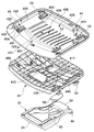
- the seat 4 is provided with an outer shell 41 mounted on the seat frame 3 and the outer shell 41 as shown in FIGS. 1, 2, 4, 5, and 7 to 12.
- a seat main body 42 having an inner shell 421 is provided.
- a slide guide mechanism 43 for sliding the inner shell 421 back and forth with respect to the outer shell 41, and the inner shell 421 moved to a desired sliding position.
- a slide positioning mechanism 44 is provided for locking.
- the outer shell 41 has a load receiving surface 411 for receiving a load from a seated person on the upper surface side.
- the load receiving surface 411 is formed around a sitting reference point T set in the second half region, and includes an inclined portion 412 that gradually rises forward from the sitting reference point T to the front side. .
- the inclined portion 412 By providing the inclined portion 412, the forward displacement of the seated person can be suppressed, and the fit at the time of sitting can be improved.
- the operation grip S1 provided below the outer shell 41 is for reaction force adjustment, and adjusts the spring preload of the tilt reaction force generation mechanism 24 provided in the support base 2. ing.
- a height adjusting lever S2 for adjusting the height position of the seat 4 On the lower surface of the outer shell 41, a height adjusting lever S2 for adjusting the height position of the seat 4, a tilt locking lever S3 for locking the backrest 6 at a desired locking position, A push button S4 for locking the slide position for operating the slide guide mechanism 43 is provided.
- a forward tilting lever S5 for operating a seat forward tilting means 45 which will be described later, is provided at the front edge corner of the outer shell 41.
- the seat body 42 includes an inner shell 421 disposed on the outer shell 41 through a slide guide mechanism 43 so as to be slidable in the front-rear direction, a cushion 422 disposed on the inner shell 421, and the cushion. 422 and a seat skin material 423 that surrounds the lower surface of the peripheral edge 425 of the inner shell 421.
- the inner shell 421 is provided with a load transmission portion 424 for supporting a load from a seated person on the load receiving surface 411 at a portion corresponding to the load receiving surface 411.
- the inner shell 421 has a shell shape including a step portion 426 whose peripheral edge portion 425 becomes higher in the vicinity of the peripheral edge, and is integrally formed of a synthetic resin that can be elastically deformed.
- the region surrounded by the step portion 426 includes a front half shell portion 427 that can be slidably in contact with the front half region of the outer shell 41 and a rear end shell that can be slidably in close contact with the rear half region of the outer shell 41.
- the main part is composed of a part 428 and an intermediate shell part 429 that smoothly leads the front edge of the rear end shell part 428 to the rear edge of the front half shell part 427.
- the intermediate shell portion 429 is provided with the load transmission portion 424.
- This load transmission portion 424 is formed by forming a plurality of slits 420 extending in the front-rear direction in the intermediate shell portion 429 with a space in the left-right direction. In a no-load state, a space P ⁇ b> 1 is formed between the lower surface of the load transmission portion 424 and the load receiving surface 411.
- the load transmitting portion 424 can be elastically deformed relatively easily in the thickness direction due to the presence of the slit 420. That is, the load transmitting portion 424 is configured to elastically deform downward and contact the load receiving surface 411 of the outer shell 41 when receiving a load from a seated person. In other words, the load from the seated person is finally received by the load receiving surface 411 of the outer shell 41 via the load transmitting portion 424.
- the inner shell 421 is arranged on the outer shell 41 via the slide guide mechanism 43 so as to be slidable in the front-rear direction within a predetermined range.
- the seating depth dimension of the seat 4 can be changed without accompanying the interlocking shift of the load receiving surface 411. That is, as schematically shown in FIGS. 11 and 12, the seating depth dimension of the seat 4 can be changed by sliding the inner shell 421 with respect to the outer shell 41. Since 411 is provided in the outer shell 41, it does not move in conjunction with the sliding movement of the inner shell 421.
- the slide guide mechanism 43 is formed at a plurality of locations on the inner shell 421 and extends in the front-rear direction.
- the slide guide mechanism 43 is slidably inserted in the guide slits 431 and slidably contacts the upper surface of the inner shell 421 at the upper end.
- a plurality of sliders 432 having retaining heads 433 and a plurality of slider mounting portions 435 provided on the outer shell 41 to fix the lower ends 434 of the sliders 432 are provided.
- Each of the sliders 432 has a prismatic shape that can slide along the corresponding guide slit 431, and a lower end thereof is attached to the outer shell 41 with a screw (not shown).
- the inner shell 421 that is guided by the slide guide mechanism 43 configured as described above and slides in the front-rear direction can be positioned and locked at a desired slide position by the slide positioning mechanism 44.
- the slide positioning mechanism 44 includes an operation member 441 that can be moved up and down from a lower lock position to an upper lock release position, and a plurality of positioning units that selectively correspond to the operation member 441 as the inner shell 421 slides. And an engaging portion 443 for use.
- the inner shell 421 is prohibited from sliding while the operation member 441 is lowered to the lower lock position and engaged with the corresponding engagement portion 443, and the operation member 441 is moved to the upper position.
- the engagement with the engagement portion 443 is released in the state where the lock is raised to the unlocked position, and the sliding movement of the inner shell 421 is allowed.
- the operation end of the operation member 441 protrudes from the lower surface side of the outer shell 41.
- the cushion 422 is, for example, a non-woven fabric stuck on the lower surface of molded urethane. More specifically, the cushion 422 is mounted on the upper surface of the inner shell 421 and is wrapped by the seat skin 423 made of cloth or the like together with the peripheral edge 425 of the inner shell 421. .
- the seat 4 described above is supported by the support base 2 via the seat forward tilting means 45.
- the seat forward tilting means 45 is indicated by a solid line in FIG. 9 with the entire seat 4 disposed on the support base 2 as the center. In addition, it is for tilting from a standard posture (A) indicated by a thick two-dot chain line in FIG. 10 to a forward tilt posture (B) indicated by a solid line in FIG.
- the seat forward tilting means 45 is provided on the seat frame 3 supporting the whole seat 4 and the rear end portion 33 of the seat frame 3, and indirectly pivoted to the support base 2 via the back frame 5.
- the rear connecting member 46 is a shaft-like member held by a bearing portion 351 provided at the rear end portion 33 of the seat frame 3, and both end portions thereof are pivotally attached to the bearing portion 513 of the back frame 5. .
- the front connecting member 47 is a shaft-like member that is held in a long hole 364 provided in the seat front tilt guide 32 of the seat frame 3 so as to be vertically movable, and can be slid back and forth in the long hole 212 of the support base 2. Is inserted.
- the lock mechanism 48 has one end 491 supported by the seat frame 3, a gas spring 451 capable of changing the position of the other end 454 with respect to the one end 453, and a position change of the other end 454 of the gas spring 451. And a motion conversion unit 452 for converting the position of the front end portion 3 of the third front to the front connection member 47 into a vertical position change.
- the gas spring 451 can be switched between a locked state and a non-lockable state that can be expanded and contracted.
- the motion converting portion 452 has a seat front tilt base 49 attached at one end 491 to the support base 2 via the front connecting member 47 so as to be movable back and forth, and an intermediate fulcrum 401 at the other end 492 of the seat front tilt base 49. And a seat front tilt adjustment arm 40 having one rotation end 402 connected to the seat frame 3 and the other rotation end 404 connected to the gas spring 451.
- the seat forward tilt base 49 is provided with a hanging plate 495 on both left and right edges of a flat plate 493 arranged substantially horizontally, and a bearing portion 496 for holding the front connecting member 47 is formed at the front end of the hanging plate 495.
- a bearing portion 496 for holding the front connecting member 47 is formed at the front end of the hanging plate 495.
- standing walls 494 that make a pair are erected on the rear edge of the flat plate 493, and the intermediate fulcrum 401 of the seat front tilt adjustment arm 40 is pivotally attached to the standing walls 494.
- the lower surface of the flat plate 493 of the seat forward tilt base 49 is supported on the support base 2 so as to be slidable back and forth, and the downward swing of the seat forward tilt base 49 is prohibited.
- the seat forward tilting base 49 and the front connecting member 47 are moved in the front-rear direction. Configured to move to.
- the seat forward tilt adjustment arm 40 has a width dimension that can be disposed between the upright walls 494, and has an L-shape in side view that bends at the position of the intermediate fulcrum 401 pivotally attached to the upright wall 494. ing.
- a shaft-like protrusion 403 is provided on one rotation end 402 of the seat front tilt adjustment arm 40.
- the shaft-like protrusion 403 is pivotally supported by the arm receiving portion 362 of the seat front tilt guide 32 of the seat frame 3 so as to be rotatable.
- a shaft hole 405 is formed in the other rotation end 404 of the seat front tilt adjustment arm 40.
- the rotating end 404 is pivotally attached to the other end 492 of the gas spring 451 through a connecting shaft 406 inserted into the shaft hole 405.
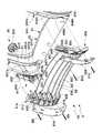
- the back frame 5 has an L-shape in a side view having a rising portion.
- the left and right dorsal support rods 51 extending horizontally in the front-rear direction, the left and right connecting members 52 attached to the rear ends of the dorsal support rods 51 to form the rising portion, and the left and right dorsal support rods 51 are coupled.
- a horizontal member 53 a horizontal member 53.
- the back frame 5 that supports the backrest 6 is supported by the support base 2 provided on the leg body 1, and the left and right back support rods 51 extending rearward, and the rear ends of these back support rods 51.
- the left and right connecting members 52 extending upward are mainly configured, and the connecting members 52 are respectively attached to the upper sides of the left and right back support rods 51, and the lower end portion of the backrest 6 is supported via the connecting members 52. ing.
- Each back support rod 51 is opened to the inside and is integrally formed by aluminum die casting.
- the base end portion of each back support rod 51 has a boss portion 511 fitted to the end portion of the main shaft 22 and is fixed to the attachment portion 235 of the bracket 23 using a bolt (not shown) in the vicinity of the base end portion.
- An intermediate rib 512 is provided.
- An intermediate portion of each back support rod 51 includes a bearing portion 513 for pivotally attaching the rear connecting member 46.
- the tip of each back support rod 51 has a mounting base 514 for screwing the horizontal member 53 and a plate-like connecting member mounting protrusion 515 extending integrally upward.
- the left and right back support rods 51 can be pivoted to the support base 2 by screwing the intermediate rib 512 to the mounting portion 235 of the bracket 23 with the boss portion 511 fitted to the main shaft 22. It is attached.
- the connecting member 52 has a shape that fits between the left and right side edges of the backrest 6 in a front view. Each of the connecting members 52 is interposed between the backrest 6 and the backrest 51, and is separate from the backrest 51 and the backrest 6, respectively. Each connecting member 52 is integrally provided with facing walls 54 and 55 that form a pair each provided with opposing pressing surfaces 541 and 551.
- each connecting member 52 includes an upper facing wall 54 that supports the lower edge of the backrest 6, a lower facing wall 55 disposed below the upper facing wall 54, both the facing walls 54, A base end side connecting wall 56 that integrally connects the base end sides of 55, and a back side connecting wall 57 that connects the front edge portions excluding the front end portions of the two facing walls 54, 55; It is molded integrally by die casting.
- a back mounting projection 542 having a nut portion 545 for mounting the back 6 is provided on the upper surface of the upper facing wall 54.
- the upper facing wall 54 has an escape hole 544 for preventing interference with a first mounting bolt B4 for mounting an armrest 7 described later provided on the base end side, and an armrest described later provided on the distal end side. And a nut portion 545 for attaching 7.
- the lower facing wall 55 has a bolt insertion hole 552 corresponding to the first mounting bolt B4 and a bolt insertion hole 553 for inserting the second mounting bolt B5 for screwing into the nut portion 545. Is provided.
- the lower facing wall 55 is formed with an opening 554 into which the connecting member mounting protrusion 515 can be inserted.
- the proximal-side coupling wall 56 is for rigidly coupling the proximal ends of the upper and lower facing walls 54 and 55, and the left and right back support rods are disposed between the inner side surfaces of the left and right proximal-side coupling walls 56.
- a space P ⁇ b> 2 that is continuous with the space P ⁇ b> 3 formed between 51 is formed.
- the back side connecting wall 57 is connected to the connecting member mounting protrusion 515 by a bolt (not shown) inserted from the rear in a state where the connecting member mounting protrusion 515 inserted into the opening 554 of the lower facing wall 55 is overlapped. It is fixed to the connecting member 52. That is, the back side coupling wall 57 is provided with a nut portion 571, and a bolt insertion hole 516 is formed in the connecting member mounting projection 515 so as to coincide with the nut portion 571. .
- the connecting member 52 is fixed to the back support rod 51 by the bolt screwed to the nut portion 571 through the bolt insertion hole 516.
- each connecting member 52 has a free end structure on the front end side, and are configured so that the pressing surfaces 541, 551 can be brought close to each other by utilizing elastic deformation of the members.
- a mounting region 58 that is opened rearward is formed by the facing walls 54 and 55 having at least the clamping surfaces 541 and 551 and the back side coupling wall 57.
- the attachment region 58 extends in the left-right direction along the lower edge of the backrest 6 on the back surface of the chair body C1 provided with the backrest 6, and the armrest 7 as an optional member is attached to the attachment region 58. I try to install it. That is, the attachment region 58 is formed by recessing a specific portion of the chair body C1, and specifically, is provided on the connecting member 52 that is a rising portion of the back frame 5.
- the horizontal member 53 is for connecting the front ends of the back support rods 51, and both ends thereof are fixed to the mounting bases 514 of the back support rods 51 by bolts B ⁇ b> 6.
- a gas spring 50 for backward tilt locking is disposed in the space P3.
- the gas spring 50 has a function of fixing the rearward tilting operation of the back frame 5 at a desired position in the locked state, and in the unlocked state, the gas spring 50 generates the biasing force of the tilting reaction force generating mechanism 24 by its elastic repulsive force. It has a function to assist.
- the backrest 6 includes a frame-like back support member 61 called a so-called back frame, and a back support member 61. It is provided with a mesh-like tension member 62 that is an exterior material that is tensioned and receives the load of a seated person, and a lumbar support device 8 that is provided on the back support member 61. Is attached.
- the back support member 61 has a gate shape including at least left and right side frames 64 and an upper frame 66 disposed between the upper ends of the side frames 64.
- the back support member 61 is integrally formed of synthetic resin, and includes a left and right side frame 64, a lower frame 65 that joins the lower ends of the side frames 64, and an upper end of the side frame 64. And an upper frame 66 for joining the two.
- Each of the side frames 64 includes side frame bodies 641a and 642a that form the side edges of the backrest 6, and a lumbar support member that is assembled in the side frame bodies 641a and 642a and forms a part of the lumbar support device 8. 81a and 82a.
- the side frame bodies 641a and 642a are arranged integrally with a first frame forming a front frame portion having a first back surface 643 and a rear side of the first frame, and are attached to the first back surface 643. And a second frame forming a rear frame portion having an adjacent second back surface 644.
- the first back surface 643 and the second back surface 644 are flush with each other in the upper portion 646, but are formed so as to be gradually separated in the front-rear direction from the middle toward the bottom. That is, the second back surface 644 is set so as to be gradually located rearward with respect to the first back surface 643, and the entire side frame bodies 641a and 642a gradually increase in thickness in the front-rear direction from the middle. It has a form that increases.
- the front frame portion and the rear frame portion are largely separated in the front-rear direction in the protruding portion corresponding to the vicinity of the waist of the seated person with the center portion protruding most forward, and in the front-rear direction arranged in this portion
- the front frame part and the rear frame part are connected by the extending wall. Therefore, the side frame main bodies 641a and 642a are configured so that the strength of the portion corresponding to the waist of the seated person can be increased and the lumbar support device 8 can be attached to this portion.
- the side frame main bodies 641a and 642a have a waist part 645 that protrudes most forward slightly below the center part and the two back faces 643 and 644 are most separated from each other, and is inclined upward from the waist part 645 while being inclined rearward.
- the waist portions 645 of the side frame bodies 641a and 642a include bottom walls 647b and 648b, left and right side walls 647d and 648d, top walls 647e and 648e, and rear walls 647f and 648f, and are opened forward. Further, lumbar mounting spaces 647a and 648a, which are the lumbar device mounting portions, are formed.
- the left lumbar mounting space 647a of the left side frame body 641a in the front view has a deeper shape than the right lumbar mounting space 648a of the right side frame body 642a in the front view.
- a rear surface 647g of the rear wall 647f forming the left lumbar mounting space 647a partially protrudes rearward from the first and second rear surfaces 643 and 644.
- Bolt insertion holes 647c and 648c corresponding to the nut portion 545 of the connecting member 52 are formed in the bottom walls 647b and 648b of the left and right side frame bodies 641a and 642a, and these bolt insertion holes 647c and 648c are viewed from above through the bolt insertion holes 647c and 648c.
- the back support member 61 is fastened to the connecting member 52 by bolts B ⁇ b> 7 and B ⁇ b> 8 screwed to the upper half of the nut portion 545.
- An attachment groove 649 for accommodating the end edge of the tension member 62 is formed in the vicinity of the front edge of the side frame 64.
- the lower frame 65 is integrated with a central portion 651 located in the center in the left-right direction, and extends obliquely upward while gradually protruding forward from both ends of the central portion 651 and is continuously integrated with the lower inner surface of the side frame 64.
- the left and right end portions 652 are integrally provided, and the left and right end portions 652 are attached to the left and right connecting members 52.
- the lower frame 65 has a hollow body shape opened downward, and includes a front structural wall 653, a rear structural wall 656 provided on the rear side of the front structural wall 653, and the rear structural wall. And a decorative wall 658 provided on the rear side of 656.
- the front structural wall 653 includes a plurality of bolt insertion holes 654 having counterbore holes through which the head of the bolt B1 can pass on the front end side. Then, the back support member 61 is fixed to the connecting member 52 by screwing the bolt B1 inserted from the front side into the bolt insertion holes 654 into the nut portion 543 of the backrest mounting projection 542 of the connecting member 52. ing. That is, the back mounting protrusion 542 of the connecting member 52 is inserted between the front structural wall 653 and the rear structural wall 656 of the lower frame 65, and the lower end of the front structural wall 653 on the upper surface of the connecting member 52.
- the back support member 61 is attached to the connecting member 52 in a state where the lower end of the rear structural wall 656 is in contact.
- the back surface 59 of the connecting member 52 and the back surface 657 of the rear structure wall 656 of the lower frame 65 are set to be flush with each other.
- the back surface 657 of the rear structure wall 656 of the lower frame 65 is continuous with the first back surface 643 of the side frame 64
- the back surface 659 of the decorative wall 658 is the second back surface of the side frame 64. It is continuous with 644.
- An attachment groove 655 for accommodating the end edge of the tension member 62 is formed at the lower end of the front structural wall 653.
- the upper frame 66 connects the upper ends of the left and right side frames 64, and is an edge fixing portion for fixing the edge of the tension member 62 to the edge 667 of the upper edge of the back support member 61.
- a groove 661 is provided.
- the upper frame 66 is provided on the front side of the mounting groove 661, a backing curved surface 662 capable of backing up the tension member 62 and smoothly leading to the mounting groove 661, and an optional member provided on the rear side of the mounting groove 661.
- a groove 663 for detachably attaching a mounting portion of a certain hanger.
- the groove 663 is formed along the end edge 667, and the width dimension is gradually changed from the center toward the outer side.
- the groove 663 has a width dimension, which is a separation distance L1 between the inner surface 664 on the front side and the inner surface 665 on the rear side, set to be gradually smaller from the center toward the left and right outer sides.
- the rear inner side surface 665 is formed to have a V-shape that is flat in a rear view and has a ridge line corresponding portion 666 corresponding to the ridge line formed in the attachment portion of the option member at the center.
- the backrest 6 includes a visual recognition edge 621 on the seating surface side of the tension member 62 and the edge fixing as viewed from the direction in which the end edge 667 of the back support member 61 extends.
- the separation distance L2 from the viewing edge 622 on the fixed side fixed to the portion is partially different.
- the separation distance L2 of the tension member 62 fixed to the upper frame 66 is gradually decreased from the center toward the outer side. That is, in this embodiment, an attachment groove 661 that opens in the direction in which the end edge 667 extends is formed in the end edge 667 of the upper frame 66, and the edge of the tension member 62 is inserted into the attachment groove 661. It is fixed.
- the visible edge on the side fixed to the mounting groove 661 is referred to as the fixed-side visual edge 622.
- the “direction in which the end edge 667 extends” means a direction in which the center line in the thickness direction of the upper frame 66 extends as shown in FIGS. 2 and 20, and the mounting groove 661 also extends along this direction. Is formed.
- the visible edge on the side forming the seating surface guided by the backing curved surface 662 is referred to as the viewing edge 621 on the seating surface side.
- the tension member 62 has a mesh shape that receives the load of the seated person. More specifically, the tension member 62 has its left and right edges inserted and fixed in the mounting groove 642 of the side frame 64, its lower edge inserted and fixed in the mounting groove 655 of the lower frame 65, and its upper edge fixed. By being inserted into the mounting groove 661 of the upper frame 66 and being fixed, it is stretched on the back support member 61 having a frame shape.
- the lumbar support device 8 includes the left and right side frames 64, a plurality of lines 83 extending between the side frames 64, and a line in another line by an external force applied to the lines 83 in a specific line. And a tension state adjusting mechanism 84 that reciprocally changes the tension of the strip 83.
- the plurality of linear bodies 83 are arranged in parallel to each other, and the “row” is used for convenience to count the linear bodies 83 that are extended in the left-right direction. It is.
- the left side frame 64 in the front view includes the side frame main body 641a, a lumbar support member 81a that is disposed in the left lumbar mounting space 647a of the side frame main body 641a and supports the linear body 83, and the lumbar support member. And a cover 81d covering the front side of 81a.
- the lumbar support member 81a and the cover 81d are fastened together with a bolt B9 inserted from the front side to the front end of a mounting boss 647h protruding from the rear wall 647f of the side frame body 641a.
- the main part of the tension state adjusting mechanism 84 is disposed between the lumbar support member 81a and the rear wall 647f.
- the lumbar support member 81a is provided with a plurality of bending guide portions 81b that guide the rear end while slidably supporting the left end portions 831 of the plurality of lines 83, and these bending guide portions.
- the front side of 81b is closed by the cover 81d.
- the right side frame 64 in the front view includes the side frame main body 642a, a lumbar support member 82a disposed in the right lumbar mounting space 648a of the side frame main body 642a, and a cover that covers the front side of the lumbar support member 82a. 82d.
- the lumbar support member 82a and the cover 82d are fastened together with a bolt B10 inserted from the front side to the front end of a mounting boss 648h provided on the rear wall 648f of the side frame body 642a.
- the lumbar support member 82a includes a plurality of linear guide portions 82b that slidably support the right end portion 834 of the plurality of lines 83, and outer ends of the linear guide portions 82b that are vertically adjacent to each other. And a curved guide portion 82c having a semicircular arc shape (U-shape) that smoothly continues, and the front sides of the linear guide portion 82b and the curved guide portion 82c are closed by the cover 82d. More specifically, the lumbar support member 82a is provided with curved guide portions 82c that form a U-shaped groove in a lateral direction when viewed from the front, at three locations in the vertical direction. The right end 834 is fixed so that it cannot slide.
- the striated body 83 is made of a wire that can be flexibly deformed, and the plurality of rows of striated bodies 83 are made of a single wire material. That is, as shown in FIGS. 21 to 24, except for the left end portion 832 of the uppermost line 83 and the left end 833 of the lowermost line 83.
- the linear members 83 in each row are integrally continuous in the lumbar mounting spaces 647a and 648a.
- the wire 83 in each row and the connecting wire 835 that connects the ends 831 and 834 of the adjacent wire 83 in the side frame 64 are constituted by one wire material. .
- the linear bodies 83 in each row are arranged in parallel in the left-right direction between the vertically oriented portions of the left and right side frames 64 extending in the up-down direction.
- the line 83 in each row is located in the vicinity of the tension member 62 that receives the load of the seated person, and is movable relative to the tension member 62.
- the linear bodies 83 in each row are arranged in a state of being stretched between the side frames 64, and come into contact with the tension members 62 deformed rearward when seated. Therefore, the outer periphery is individually covered with the covering member 836 for the purpose of preventing the tension member 62 from being damaged.
- the covering member 836 is separate from the striate body 83 and has a tube shape covering the entire circumference of the striate body 83. Specifically, the covering member 836 covers the entire circumference of the filament 83, that is, a main tube 837 that covers the entire circumference of the filament 83 in a cross-sectional view, and both ends of the main tube 837. And a sub-tube 838 for preventing exposure that covers the frame proximity portion of the linear body 83 including the portion.
- the sub tubes 838 are provided on both the left and right sides, and are fitted to the left and right side frames 64, respectively.
- each filament 83 passes through the main tube 837.
- the tension state adjusting mechanism 84 is supported by the side frame main body 641a and disposed in the lumbar mounting space 647a, and a center portion in the vertical direction is rotatably supported by the fulcrum member 841.
- an adjusting arm 842 capable of performing a balance operation in the front-rear direction in the lumbar mounting space 647a.
- the fulcrum member 841 and the adjustment arm 842 are disposed between the lumbar support member 81a and the rear wall 647f.
- the adjustment arm 842 includes an end portion attaching portion 843 for attaching the end portions of the wire 83 provided at both upper and lower end portions, and a plurality of curved guide portions 844 provided in the middle for smoothly guiding the wire material. ing.
- Each curved guide portion 844 is mainly composed of a semi-arc-shaped (U-shaped) guide protrusion 845 formed on the side surface of the adjustment arm 842, and a wire end is provided on the protruding end of the guide protrusion 845.
- a flange 846 for preventing the material from coming off is integrally provided.
- a plurality of rows of line bodies 83 are arranged in parallel with a space between the left lumbar support member 81a and the right lumbar support member 82a, and the left end of the line bodies 83 of each adjacent row is arranged.
- the left connecting wire portion 835 that connects the portions 831 is guided rearward by the bending guide portion 81b and is slidably supported by the curved guide portion 844 of the adjusting arm 842, and the adjacent line members
- a right connecting line portion 835 that connects the right end portions 834 of 83 is slidably supported by the curved guide portion 82c of the right lumbar support member 82a.
- the left end portion 832 of the uppermost line 83 is guided to the rear by the bending guide portion 81b and is rotatably attached to the upper end mounting portion 843 of the adjustment arm 842.
- the left end portion 833 of the lowermost line 83 is guided rearward by the bending guide portion 81b and rotatably attached to the lower end attachment portion 843 of the adjustment arm 842. Yes.
- the lumbar support device 8 is also provided with a tension adjusting unit 85 for changing the average tension of the line 83 in each row.
- the tension adjusting unit 85 is for changing the holding position of the fulcrum member 841 in the front-rear direction.
- the tension adjustment unit 85 is provided with a screw hole 851 in the fulcrum member 841 and a screw rod 852 screwed into the screw hole 851 on the side.
- An operation grip 853 for rotating the screw rod 852 is provided at the outer penetrating end of the screw rod 852 so as to be rotatably inserted in the rear wall 647f of the frame main body 641a.
- the front end of the screw rod 852 is rotatably supported by the lumbar support member 81a.
- the adjusting arm 842 is appropriately rotated in the front-rear direction by an external force applied to the linear body 83 in a specific row, and the tension of the linear body 83 in other rows is relatively changed. It is like that. Specifically, for example, when the upper linear member 83 is pushed rearward, the upper end side of the adjustment arm 842 is pulled forward and rotated, that is, the fulcrum member 84 that is the rotation axis of the adjustment arm 842 is a boundary. Thus, the tension of the linear body 83 is changed relative to the upper and lower sides, and the tension of the linear body 83 in another row attached or held to the lower end side of the adjustment arm 842 becomes stronger.
- the lumbar support device 8 configured as described above includes the left and right lumbar support members 81a and 82a, the adjustment arm 842 disposed on the rear side of the lumbar support members 81a and 82a, the lumbar support members 81a and 82a, and the adjustment.
- the threaded rod 852 of the tension adjusting unit 85 includes a threaded rod main body 854 screwed to the fulcrum member 841 and a retaining rod 855 screwed to the rear end of the threaded rod main body 854.
- the screw rod main body 854 is passed through the rear wall 647f of the side frame main body 641a with the retaining rod 846 removed, and the screw rod main body 854
- An operation grip 853 is attached to the outer periphery of the penetrating end, and a retaining rod 855 is screwed to the penetrating end.
- the lumbar support members 81a and 82a are screwed and fixed to the side frame bodies 641a and 642a together with the covers 81d and 82d while being accommodated in the lumbar mounting spaces 647a and 648a.
- the synchro-rocking mechanism R supports the front connection member 47 held by the seat frame 3 to the support base 2 so as to be movable back and forth, and is held by the seat frame 3. Further, the rear connecting member 46 is pivotally supported on the back frame 5 so that the backward tilting operation of the backrest 6 and the sinking operation of the seat 4 are interlocked.
- the synchro-rocking mechanism R is provided such that the front end side of the seat frame 3 that supports the seat 4 is connected to the front end portion of the support base 2 via the front connection member 47 so as to be movable back and forth, and the rear frame 3 The end side is pivotally supported on the back frame 5 via the rear connecting member 46.
- the front connecting member 47 is slidably supported by a long hole 212 provided in the front end portion 34 of the support base 2 and extending in the front-rear direction.
- the rear connecting member 46 also serves as a pivot point of the seat forward tilting means 45 described above, and is rotatable on a bearing portion 513 provided on the back support rod 51 of the back frame 5.
- the armrest 7 is an optional member that is detachably attached to the chair body C1, as shown in FIGS. 1 to 5, 13 to 18, 22, 23, 26, and 27. And an elbow frame 71 having a base end portion 73 attached to the attachment region 58 of the connecting member 52 of the chair main body C1 and an armrest main body 72 provided at a distal end portion 75 of the elbow frame 71.
- the elbow frame 71 includes a base end portion 73 that extends along the lower edge of the backrest 6, an intermediate bend portion 74 that is provided continuously with the base end portion 73 and bends forward and upward, and this intermediate bend. It is provided with the front-end
- the armrest main body 72 is provided at the upper end of the distal end portion 75.
- the armrest main body 72 includes an elbow rest 721 formed integrally with the elbow frame 71 and an elbow rest 722 attached on the elbow rest 721.
- the elbow receiver 721 is integrally formed with the elbow frame 71 and a synthetic resin.
- the base end portion 73 of the elbow frame 71 corresponding to the base end portion of the armrest 7 has a shape that fits into the recessed mounting region 58 of the connecting member 52, and mainly from the rear side to the mounting region 58. It is designed to be fitted.
- the base end portion 73 of the elbow frame 71 includes an upper surface 731 that is in close contact with or very close to the facing wall 54 on the connecting member 52, a lower surface 732 that is in close contact with or very close to the lower facing wall 55, and the base A base end surface 733 that is in close proximity to or very close to the end-side coupling wall 56, a back surface 734 that is flush with the back surface 59 of the connecting member 52, and a front surface 735 that corresponds to the back-side connecting wall 57 of the connecting member 52. It is a thing.
- the front surface 735 includes an inner region 76 that faces the head of the bolt, an intermediate region 77 that abuts on the inner coupling wall 57, and an outer region that is located outside the outer edge 572 of the inner coupling wall 57. 78.
- an inner stepped portion 79 that engages with the edge of the connecting member mounting protrusion 515 of the back support rod 51 is formed.
- an outer stepped portion 70 is formed at the boundary between the intermediate region 77 and the outer region 78 so as to engage with the outer edge 572 of the back side coupling wall 57.
- the base end portion 73 of the elbow frame 71 is fixed to the connecting member 52 using the first mounting bolt B4 and the second mounting bolt B5. More specifically, the base end portion 73 of the elbow frame 71 has a first bolt insertion hole 736 whose axis is aligned with the bolt insertion hole 552 and the escape hole 544 of the connection member 52, and the connection member 52.
- the bolt insertion hole 553 and the nut part 545 are provided with a second bolt insertion hole 738 whose axis is aligned.
- An embedded nut 737 is disposed in the middle of the first bolt insertion hole 736.
- the base mounting end B5 is inserted into the bolt insertion hole 552 of the connecting member 52 and the first bolt insertion hole 736 of the elbow frame 71 from below, and is screwed into the embedded nut 737 and tightened to tighten the base end.
- the portion 73 is brought into close contact with and fixed to the facing wall 55 below the connecting member 52.
- the tip of the first mounting bolt B4 that has passed through the embedded nut 737 is inserted into a relief hole 544 provided in the upper facing wall 54.
- a nut portion provided on the facing wall 54 above the connecting member 52 includes a second mounting bolt B5 inserted from below into the bolt inserting hole 553 of the connecting member 52 and the second bolt inserting hole 738 of the elbow frame 71.
- the base end portion 73 is brought into close contact with and fixed to the upper and lower facing walls 54 and 55 of the connecting member 52 by screwing and tightening to the lower half portion of 545.
- the base end portion 73 is clamped from above and below by the clamping surface 541 of the upper facing wall 54 and the clamping surface 551 of the lower facing wall 55 by the tightening force of the second mounting bolt B5 as a fastening member. It is fixed. That is, the tip portions of the upper and lower facing walls 54 and 55 that are not supported by the inner side coupling walls 57 form a cantilever support structure. Therefore, the base end portion 73 is firmly fixed to the connecting member 52 by elastically deforming the tip portions of the upper and lower facing walls 54 and 55 with the second mounting bolt B5 and bringing the pressing surfaces 541 and 551 closer to each other. Has been.
- a cover 7a which is one of optional members, is attached instead of the armrest 7.
- the cover 7 a is attached to the attachment region 58 in the connecting member 52 of the chair body C ⁇ b> 1 and extends along the lower edge of the backrest 6. That is, the cover 7a has the same shape as the base end portion 73 of the armrest 7 described above, and has a shape that fits into the recessed mounting region 58 of the connecting member 52.
- the cover 7a is attached to the chair body C1. In the mounted state, the top edge of the upper and lower facing walls 54 and 55 of the connecting member 52 and the outer edge of the cover 7a are configured to coincide with each other.
- the linear member 83 is linear even when the linear member 83 moves relative to the exterior material.
- the body 83 and the tension member 62 do not interfere with each other. Accordingly, it is possible to suitably avoid damage to the tension member 62 caused by the tension member 62 and the linear body 83 sliding on each other.
- the tension member 62 that is a mesh that receives the load of the seated person is an exterior material that receives the load of the seated person, and the tension member 62 is stretched on the back support member 61 having a frame shape. Can be secured.
- the wire 83 is a wire that can be flexibly deformed, it has excellent strength and a wide range of options.
- the wire is generally a stranded wire, and when the wire and the tension member 62 slide on each other, the tension member 62 is easily damaged.
- the outer periphery is covered with the covering member 836. Therefore, damage to the tension member 62 can be suitably avoided.
- the covering member 836 is a tube-like member that covers the entire outer periphery of the linear member 83 in a cross-sectional view, the damage to the tension member 62 can be more reliably alleviated.
- the covering member 836 includes a main tube 837 that covers the entire circumference of the linear body 83, and an exposure prevention sub-tube 838 that covers the frame adjacent portion of the linear body 83 including both ends of the main tube 837. Therefore, the sub-tube 838 can prevent the end of the linear body 83 not covered by the main tube 836 from being exposed when the linear body 83 moves in the left-right direction. Therefore, damage to the tension member 62 when the linear body 83 moves relative to the tension member 62 can be securely relieved. Moreover, since the sub tube 838 prohibits the end of the linear body 83 from being exposed when the linear body 83 moves in the left-right direction, the appearance of the end of the linear body 83 is exposed.
- a lumbar support device 8 including a side frame 64 and a plurality of rows of linear bodies 83 spanned between the side frames 64 is provided at a portion of the backrest 6 that projects to the forefront. Therefore, the seated person's waist can be stably held.
- the lumbar support device 8 spans the left and right lumbar support members 81a and 82a, the adjustment arm 842 arranged on the rear side of the lumbar support members 81a and 82a, and the lumbar support members 81a and 82a and the adjustment arm 842. Since it has a unit 86 provided with a passed linear body 83 and a tension adjusting portion 85 excluding the operation grip 853, this unit 86 is incorporated into the side frame main bodies 641a and 642a from the front side. Assembling work can be made more efficient by laying the relatively hard wire 83 on the lumbar support members 81a and 82a first.
- a piano wire or the like may be used in addition to the (stranded) wire used in the above-described embodiment.
- the covering member in addition to the tube-shaped member employed in the above-described embodiment, the following member may be used. In the description of this aspect, the same names and symbols are assigned to the portions corresponding to those in the above-described embodiment. That is, as shown in FIG. 28, a covering member 839 that has a sheet shape and has a plurality of linear body accommodation holes 839a that can accommodate the linear bodies 83, that is, individually covers the outer circumferences of the linear bodies in each row. May be adopted. Moreover, you may employ
- a normal cloth or the like can be used in addition to the mesh-like material as in the embodiment described above.
- the tension of the striatum can be changed individually, but the tension of the striatum may not be changeable.
- all the striated bodies are made of a single wire material, and both ends of the wire material are held by the end mounting portions, but other configurations, for example, all Each line is composed of one wire material and all the lines in each row are connected in a loop, or multiple lines are divided into groups, and each group of lines is looped. In other words, the outer periphery of each row of striates may be individually covered with a covering member.
- the present invention is mainly applied to the lumbar support portion of the backrest.
- the present invention may be applied to other portions of the backrest, and the present invention is applied to the entire backrest. You may apply.
- the present invention may be applied to a part or the whole of the seat. Of course, the present invention may be applied to both the backrest and the seat.
- the chair of the present invention is arranged with an exterior material that receives the load of the seated person in the vicinity of the striated body, but even if the striated body is a chair in a mode that receives the load of the seated person directly,
- an effect similar to that of the present invention that is, an effect that damage to clothes of the seated person can be suppressed can be obtained. That is, in a chair provided with a pair of frames constituting a seat or a backrest and a linear body stretched between the frames, it is separated from the linear body and the outer periphery of the linear body is individually covered.
- a covering member will interpose between a filament and a seated person's clothes. Therefore, the linear body does not interfere with the seated person's clothes, and damage to the seated person's clothes can be suppressed.
Abstract
背凭れ又は座を構成する枠間に張設された状態で配された線条体(83)が外装材に摺接しつつこれらが相対移動した際に外装材が傷むという不具合の発生を抑制すべく、着座者の荷重を受ける外装材である張り部材(62)と、この張り部材(62)の近傍に位置させて左右の側枠(64)間に張設された状態で配され前記張り部材(62)に対して相対移動可能な線条体(83)と、この線条体(83)と別体をなし当該線条体(83)の外周を個別に被覆する被覆部材(836)とを具備する構成を採用する。
Description
本発明は、オフィス等において好適に用いられる椅子に関する。
従来より、椅子の座又は背凭れにおいて、座面又は背凭れ面を有する外装材と、この外装材の座面又は背凭れ面と反対側に配され着座者の荷重を支持する線条体とを備える構成が考えられている(例えば、特許文献1を参照)。
ところで、このような構成を採用した椅子において、以下に述べるような不具合が発生し得る。すなわち、従来のものは、線条体が外装材に直接接しているので、着座者の体重移動等に伴い、線条体が外装材に摺接しつつこれらが相対移動する。特に、このような椅子に用いられる線条体には、金属線をよりあわせて形成したワイヤが採用されることが多く、ワイヤが外装材に摺接しつつ移動すると、外装材が損傷ないし破損することがある。
本発明は以上の点に着目し、線条体が外装材に摺接しつつこれらが相対移動した際に外装材が傷むという不具合の発生を抑制することを目的とする。
以上の課題を解決すべく、本発明に係る椅子は、以下に述べるような構成を有する。すなわち本発明に係る椅子は、着座者の荷重を受ける外装材と、この外装材の近傍に位置させて枠間に張設された状態で配され前記外装材に対して相対移動可能な線条体と、この線条体と別体をなし当該線条体の外周を個別に被覆する被覆部材とを具備する。
このような構成であれば、被覆部材により線条体の外周を被覆しているので、線状体が外装材との間で相対移動した際にも線状体と外装材とが干渉しない。従って、外装材の傷みを和らげることができる。
線条体がその延伸方向に移動可能なものにおいて、線条体が外装材に対して相対移動する際の外装材の傷みを確実に和らげることができる構成の一例として、前記被覆部材が、前記線条体の断面視における外周を全域に亘って覆うメインチューブと、このメインチューブの両端部を含め前記線条体の枠近接部分を覆う露出防止用のサブチューブとを備えたものが挙げられる。
前記線条体の配置態様の一例として、背凭れ及び座の少なくとも一方を構成する左右の側枠間に張設されたものが挙げられる。
本発明の効果を好適に得られる構成の一例として、前記線条体の張力を変更可能であるものが挙げられる。
前記枠間に複数行の線条体が架け渡されており、特定行の線条体に加わる外力により他の行の線条体の張り具合を個別に変更されるように構成されているものであれば、本発明の効果をさらに好適に得ることができる。
そして、このような線条体及び被覆部材を好適に適用する態様として、背凭れの最も前方に張り出した部位に、側枠と、これら側枠間に架け渡された複数行の線条体とを具備してなるランバーサポート装置を備えているものが挙げられる。
本発明によれば、線条体が外装材との間で相対移動した際に外装材が傷むという不具合の発生を抑制することができる。
以下、本発明をシンクロチルト式の事務用回転椅子Cに適用した場合の一実施形態につき、図面を参照して説明する。
この椅子Cは、図1~図4に示すように、椅子本体C1に肘掛け7を装着したものである。
前記椅子本体C1は、脚体1と、この脚体1の上部に支持され水平旋回可能な支持基部2と、この支持基部2に座フレーム3を介して支持された座4と、前記支持基部2に背フレーム5を介して後傾動作可能に支持された背凭れ6とを具備してなる。
<脚体>
前記脚体1は、図1~図5に示すように、キャスタ13を有した脚羽根タイプの脚ベース11と、この脚ベース11の中心部に立設した脚支柱12とを具備してなる。前記脚支柱12は、ガススプリングを主体に構成された通常のもので、この脚支柱12の上端部に前記支持基部2が取り付けられている。
前記脚体1は、図1~図5に示すように、キャスタ13を有した脚羽根タイプの脚ベース11と、この脚ベース11の中心部に立設した脚支柱12とを具備してなる。前記脚支柱12は、ガススプリングを主体に構成された通常のもので、この脚支柱12の上端部に前記支持基部2が取り付けられている。
<支持基部>
前記支持基部2は、図2、図5、図6、図8~図10及び図13に示すように、前記脚体1によって水平旋回可能かつ上下方向に昇降可能に支持されたもので、前記脚支柱12に装着されたハウジング21と、このハウジング21の両側壁211に貫装される背凭れ支持用の主軸22と、この主軸22まわりに回動可能に設けられ第1の回動端231に反力受け軸232を備えるとともに第2の回動端233に前記背フレーム取付用の取付部235を備えたブラケット23と、このブラケット23の反力受け軸232を付勢して前記背凭れ6の後傾動作に対して弾性反発力を発生させる傾動反力発生機構24とを具備してなる。
前記支持基部2は、図2、図5、図6、図8~図10及び図13に示すように、前記脚体1によって水平旋回可能かつ上下方向に昇降可能に支持されたもので、前記脚支柱12に装着されたハウジング21と、このハウジング21の両側壁211に貫装される背凭れ支持用の主軸22と、この主軸22まわりに回動可能に設けられ第1の回動端231に反力受け軸232を備えるとともに第2の回動端233に前記背フレーム取付用の取付部235を備えたブラケット23と、このブラケット23の反力受け軸232を付勢して前記背凭れ6の後傾動作に対して弾性反発力を発生させる傾動反力発生機構24とを具備してなる。
前記ハウジング21の両側壁211の前端部には、後述する前連結部材47を前後方向にスライド移動可能に支持するための長孔212が形成されている。
前記ブラケット23は、前記ハウジング21の両側にそれぞれ設けられた対をなす板状のブラケット本体234と、これら左右のブラケット本体234の第1の回動端231同士を連結する前記反力受け軸232と、前記各ブラケット本体234の第2の回動端233に外側方に延出させて設けられた前記取付部235とを備えたものである。前記取付部235には、ねじ孔236が形成されており、このねじ孔236に螺着された図示しないボルトにより当該ブラケット23に後述する背フレーム5の背支桿51が固定されている。
前記傾動反力発生機構24は、コイルスプリング241を用いて前記反力受け軸232に弾性反発力を付与し得るように構成されたものであるが、通常のものであるため詳細な説明を省略する。
<座フレーム>
前記座フレーム3は、図2及び図5~図14に示すように、後端部33に後述する後連結部材46を保持し前記座4の全体を支持する座フレーム本体31と、この座フレーム本体31の前端部34に設けられ後述する前連結部材47を上下動可能に保持する座前傾ガイド32とを備えたものである。
前記座フレーム3は、図2及び図5~図14に示すように、後端部33に後述する後連結部材46を保持し前記座4の全体を支持する座フレーム本体31と、この座フレーム本体31の前端部34に設けられ後述する前連結部材47を上下動可能に保持する座前傾ガイド32とを備えたものである。
前記座フレーム本体31は、合成樹脂により一体に成形されたもので、左右の側枠部35を有する枠状をなしている。座フレーム本体31の側枠部35の後端部33は、前記後連結部材46を保持する軸受部351を備えている。座フレーム本体31の前記側枠部35の前端部34は、前記座前傾ガイド32を取り付けるための取付部352を備えている。また、前記両側枠部35の中間部内側には、ガススプリング取付部353が設けられている。
前記座前傾ガイド32は、前記座フレーム本体31の側枠部35間に配されるガイド本体36と、このガイド本体36を前記側枠部35の取付部352に固定するための取付片37とを備えたもので、板金素材により一体に構成されている。前記ガイド本体36は、前記座フレーム本体31の側枠部35間に嵌挿されるもので、前記座フレーム本体31の側枠部35よりも上方に位置する天壁361と、この天壁361の両側縁から下方に垂下する側壁363とを備えている。前記天壁361の前縁には、下方に湾曲しながら延びるアーム受け部362が形成されている。前記両側壁363には、前記前連結部材47を上下方向に移動可能に保持するガイド用の長孔364が形成されている。前記取付片37は、前記両側壁363から外側方に延出させた板状のもので、この取付片37を図示しないビスにより前記座フレーム本体31の下面に取り付けている。
<座>
前記座4は、図1、図2、図4、図5及び図7~図12に示すように、前記座フレーム3上に取り付けられたアウターシェル41と、このアウターシェル41上に設けられたインナーシェル421を有する座本体42とを備えたものである。前記アウターシェル41と前記インナーシェル421との間には、アウターシェル41に対してインナーシェル421を前後方向にスライド移動させるためのスライド案内機構43と、前記インナーシェル421を所望のスライド位置に移動させてロックするためのスライド位置決め機構44とが設けられている。
前記座4は、図1、図2、図4、図5及び図7~図12に示すように、前記座フレーム3上に取り付けられたアウターシェル41と、このアウターシェル41上に設けられたインナーシェル421を有する座本体42とを備えたものである。前記アウターシェル41と前記インナーシェル421との間には、アウターシェル41に対してインナーシェル421を前後方向にスライド移動させるためのスライド案内機構43と、前記インナーシェル421を所望のスライド位置に移動させてロックするためのスライド位置決め機構44とが設けられている。
前記アウターシェル41は、上面側に着座者からの荷重を受け止める荷重受け面411を有したものである。この荷重受け面411は、後半領域に設定された座位基準点Tを中心にして形成されたもので、その座位基準点Tよりも前側に前方に向かって漸次上昇する傾斜部分412を備えている。この傾斜部分412を設けることによって、着座者の前方へのずれを抑制することができるとともに、着座時のフィット感を向上させることができるようにしてある。
なお、このアウターシェル41の下方に設けられた操作グリップS1は、反力調整用のもので、前記支持基部2内に設けられた前記傾動反力発生機構24のスプリング予圧を調整するようになっている。アウターシェル41の下面には、座4の高さ位置を調整するため高さ調整用のレバーS2と、前記背凭れ6を所望のロック位置でロックするための傾動ロック用のレバーS3と、前記スライド案内機構43を操作するためのスライド位置ロック用の押しボタンS4とが設けられている。また、アウターシェル41の前縁角部には、後述する座前傾手段45を操作するための前傾用のレバーS5が設けられている。
前記座本体42は、前記アウターシェル41上にスライド案内機構43を介して前後方向にスライド移動可能に配設されたインナーシェル421と、前記インナーシェル421上に配されたクッション422と、このクッション422及び前記インナーシェル421の周縁部425下面をくるむ座表皮材423とを備えたものである。
前記インナーシェル421は、前記荷重受け面411に対応する部位に着座者からの荷重を前記荷重受け面411に担持させるための荷重伝達部分424を備えたものである。このインナーシェル421は、周縁近傍部に周縁部425側が高くなる段部426を備えたシェル状をなしており、弾性変形可能な合成樹脂により一体に成形されている。前記段部426に囲まれた領域は、前記アウターシェル41の前半領域に摺動可能に密接し得る前半シェル部分427と、前記アウターシェル41の後半領域に摺動可能に密接し得る後端シェル部分428と、この後端シェル部分428の前縁を前記前半シェル部分427の後縁に滑らかに連続させる中間シェル部分429とを主体にして構成されている。そして、前記中間シェル部分429に前記荷重伝達部分424が設けられている。
この荷重伝達部分424は、前記中間シェル部分429に前後方向に伸びる複数本のスリット420を、左右方向に間隔をあけて形成したものである。そして、無負荷状態においては、前記荷重伝達部分424の下面と前記荷重受け面411との間に空間P1が形成されている。この荷重伝達部分424は、前記スリット420の存在により、厚み方向に比較的容易に弾性変形し得るようになっている。すなわち、荷重伝達部分424は、着座者からの荷重を受けた場合に、下方に弾性変形して、前記アウターシェル41の荷重受け面411に当接するように構成されている。換言すれば、着座者からの荷重は、前記荷重伝達部分424を介して最終的に前記アウターシェル41の荷重受け面411によって受け止められるようにしてある。
そして、このインナーシェル421は、スライド案内機構43を介して前記アウターシェル41上に所定の範囲内で前後方向にスライド移動可能に配されている。その際、前記荷重受け面411の連動移行を伴うことなしに、当該座4の着座奥行寸法を変更することができるようになっている。すなわち、図11及び図12に模式的に示すように、このインナーシェル421をアウターシェル41に対してスライド移動させることによって、座4の着座奥行寸法を変更することができるが、前記荷重受け面411はアウターシェル41に設けられているため、前記インナーシェル421のスライド移動に連動して移動することはない。
前記スライド案内機構43は、前記インナーシェル421の複数個所に形成され前後方向に延びる案内スリット431と、これら各案内スリット431にそれぞれスライド自在に貫装され上端に前記インナーシェル421の上面に摺接する抜止頭部433を有した複数のスライダ432と、これら各スライダ432の下端部434を固定すべく前記アウターシェル41に設けられた複数のスライダ取付部435とを備えたものである。前記各スライダ432は、対応する前記案内スリット431に沿ってスライドし得る角柱状をなすものであり、下端が図示しないビスにより前記アウターシェル41に取り付けられている。
以上の構成をなすスライド案内機構43により案内されて前後方向にスライドするインナーシェル421は、前記スライド位置決め機構44により所望のスライド位置で位置決めしロックすることができるようになっている。
前記スライド位置決め機構44は、下ロック位置から上ロック解除位置までの間で昇降動作可能な操作部材441と、インナーシェル421のスライド移動に伴ってこの操作部材441に選択的に対応する複数の位置決め用の係合部443とを具備してなる。このスライド位置決め機構44は、前記操作部材441が前記下ロック位置に降下して対応する係合部443に係合した状態で前記インナーシェル421のスライド移動が禁止され、前記操作部材441が前記上ロック解除位置まで上昇した状態で前記係合部443との係合が解除されて前記インナーシェル421のスライド移動が許容されるようにしたものである。前記操作部材441の操作端は、前記アウターシェル41の下面側に突出させてある。操作部材441の押しボタンS4を上方に操作することで、当該操作部材441を含む座4の主要部を前記アウターシェル41に対して移動させ、座4の着座奥行寸法を変更することができるようになっている。
前記クッション422は、例えばモールドウレタンの下面に不織布を貼設したものである。詳述すれば、このクッション422は、前記インナーシェル421の上面に載設されており、前記インナーシェル421の周縁部425とともに布等により作られた前記座表皮材423によりくるまれたものである。
以上説明した座4は、座前傾手段45を介して前記支持基部2に支持されている。
<座前傾手段>
前記座前傾手段45は、図5、図6、図9及び図10に示すように、支持基部2上に配された座4の全体をその後部を中心にして、図9において実線で示すとともに図10において太い二点鎖線で示す標準姿勢(A)から、図10において実線で示す前傾姿勢(B)までの間で傾動させるためのものである。この座前傾手段45は、前記座4の全体を支持する前記座フレーム3と、この座フレーム3の後端部33に設けられ前記支持基部2に前記背フレーム5を介して間接的に枢支された後連結部材46と、前記座フレーム3の前端部34に設けられ前記支持基部2の前端部に支持された前連結部材47と、この前連結部材47に対する前記座フレーム3の前端部34の位置を上下方向に変更して所望の位置でロックするロック機構48とを備えてなる。
前記座前傾手段45は、図5、図6、図9及び図10に示すように、支持基部2上に配された座4の全体をその後部を中心にして、図9において実線で示すとともに図10において太い二点鎖線で示す標準姿勢(A)から、図10において実線で示す前傾姿勢(B)までの間で傾動させるためのものである。この座前傾手段45は、前記座4の全体を支持する前記座フレーム3と、この座フレーム3の後端部33に設けられ前記支持基部2に前記背フレーム5を介して間接的に枢支された後連結部材46と、前記座フレーム3の前端部34に設けられ前記支持基部2の前端部に支持された前連結部材47と、この前連結部材47に対する前記座フレーム3の前端部34の位置を上下方向に変更して所望の位置でロックするロック機構48とを備えてなる。
前記後連結部材46は、前記座フレーム3の後端部33に設けられた軸受部351に保持された軸状のもので、その両端部が背フレーム5の軸受部513に枢着されている。
前記前連結部材47は、前記座フレーム3の座前傾ガイド32に設けられた長孔364に上下移動可能に保持された軸状のもので、前記支持基部2の長孔212に前後スライド可能に嵌挿されている。
前記ロック機構48は、一端491を前記座フレーム3に支持させ、その一端453に対する他端454の位置を変更可能なガススプリング451と、このガススプリング451の他端454の位置変化を前記座フレーム3の前端部34の前記前連結部材47に対する上下方向の位置変化に変換する動作変換部452とを備えたものである。
前記ガススプリング451は、ロック状態と伸縮可能な非ロック状態との間で切り替え可能なものである。
前記動作変換部452は、一端491を前記前連結部材47を介して支持基部2に前後移動可能に取り付けられた座前傾ベース49と、この座前傾ベース49の他端492に中間支点401を枢着し、一方の回動端402を前記座フレーム3に接続するとともに他方の回動端404を前記ガススプリング451に接続した座前傾調整アーム40とを備えたものである。
前記座前傾ベース49は、略水平に配された平板493の左右両側縁に垂下板495を設けたもので、前記垂下板495の前端に前記前連結部材47を保持する軸受部496が形成されている。また、前記平板493の後縁部に対をなす起立壁494が立設されており、これら起立壁494に座前傾調整アーム40の中間支点401が枢着されている。この座前傾ベース49の平板493の下面は、前記支持基部2上に前後摺動可能に支持されており、座前傾ベース49の下方への回動が禁止されている。なお、後述するシンクロロッキング機構Rの作用により、背凭れ6の後傾動作に連動して座4が沈み込み動作を行う際には、前記座前傾ベース49が前記前連結部材47とともに前後方向に移動するように構成されている。
前記座前傾調整アーム40は、前記起立壁494間に配設され得る幅寸法を備えたもので、前記起立壁494に枢着された中間支点401の位置で屈曲する側面視L字形をなしている。座前傾調整アーム40の一方の回動端402には、軸状突部403が設けられている。そして、この軸状突部403を前記座フレーム3の座前傾ガイド32のアーム受け部362に回動可能に枢支させている。座前傾調整アーム40の他方の回動端404には、軸孔405が形成されている。この回動端404は、前記軸孔405に挿通した連結軸406を介して前記ガススプリング451の他端492に枢着されている。
この実施形態においては、以上説明したように、前記座フレーム3に、前記ロック機構48の全ての構成部品を組み付けてユニット化している。
<背フレーム>
前記背フレーム5は、図2、図3、図5、図9、図10、図13~図18、図22及び図23に示すように、立ち上がり部を有する側面視L字状をなすもので、ほぼ前後方向に水平に延びる左右の背支桿51と、これら背支桿51の後端に取り付けられ前記立ち上がり部を形成する左右の連結部材52と、前記左右の背支桿51を連結する横架材53とを備えている。換言すれば、背凭れ6を支持する背フレーム5は、脚体1上に設けられた支持基部2に支持されて後方に延びる左右の背支桿51と、これら背支桿51の後端から上方に延びる左右の前記連結部材52とを主体に構成されており、左右の背支桿51の上側に連結部材52をそれぞれ取り付け、それら連結部材52を介して背凭れ6の下端部を支持させている。
前記背フレーム5は、図2、図3、図5、図9、図10、図13~図18、図22及び図23に示すように、立ち上がり部を有する側面視L字状をなすもので、ほぼ前後方向に水平に延びる左右の背支桿51と、これら背支桿51の後端に取り付けられ前記立ち上がり部を形成する左右の連結部材52と、前記左右の背支桿51を連結する横架材53とを備えている。換言すれば、背凭れ6を支持する背フレーム5は、脚体1上に設けられた支持基部2に支持されて後方に延びる左右の背支桿51と、これら背支桿51の後端から上方に延びる左右の前記連結部材52とを主体に構成されており、左右の背支桿51の上側に連結部材52をそれぞれ取り付け、それら連結部材52を介して背凭れ6の下端部を支持させている。
前記各背支桿51は、内側に開放されたもので、アルミダイキャストにより一体に形成されている。各背支桿51の基端部は、前記主軸22の端部に嵌合するボス部511を有するとともに、基端部近傍に前記ブラケット23の取付部235に図示しないボルトを用いて固定される中間リブ512を備えている。各背支桿51の中間部は、後連結部材46を枢着するための軸受部513を備えている。各背支桿51の先端部は、前記横架材53をビス止めするための取付台座514を有するとともに、上方に一体に延びる板状の連結部材取付突部515を備えている。左右の背支桿51は、そのボス部511を前記主軸22に嵌合させた状態で前記中間リブ512を前記ブラケット23の取付部235にビス止めすることにより、支持基部2に回動可能に取り付けられている。
前記連結部材52は、正面視において前記背凭れ6の左右両側縁間に収まる寸法形状のものである。各連結部材52は、背凭れ6と背支桿51との間に介在させたもので、前記背支桿51及び背凭れ6とはそれぞれ別体をなしている。各連結部材52は、対向する挟圧面541、551をそれぞれ備えた対をなす対面壁54、55を一体に備えたものである。すなわち、各連結部材52は、背凭れ6の下縁を支持する上の対面壁54と、この上の対面壁54の下方に配設された下の対面壁55と、これら両対面壁54、55の基端側を一体に結合する基端側結合壁56と、前記両対面壁54、55の先端部を除く前縁部同士を結合する奥側結合壁57とを備えたもので、アルミダイキャストにより一体に成形されている。
前記上の対面壁54の上面には、背凭れ6を取り付けるためのナット部545を有した背凭れ取付突部542を備えている。上の対面壁54には、基端側に設けられた後述する肘掛け7を取り付けるための第1取付ボルトB4との干渉を防止するための逃げ孔544と、先端側に設けられた後述する肘掛け7を取り付けるためのナット部545とが設けられている。
前記下の対面壁55には、前記第1取付ボルトB4に対応するボルト挿通孔552と、前記ナット部545に螺着するための第2取付ボルトB5を挿通させるためのボルト挿通孔553とが設けられている。下の対面壁55には、連結部材取付突部515を挿入可能な開口部554が形成されている。
前記基端側結合壁56は、上下の対面壁54、55の基端を剛結するためのもので、左右の基端側結合壁56同士の内側面間には、前記左右の背支桿51の間に形成されている空間P3に連続する空間P2が形成されている。
前記奥側結合壁57は、前記下の対面壁55の開口部554に挿入した連結部材取付突部515を重ね合わせた状態で後方から挿入した図示しないボルトにより、当該連結部材取付突部515が連結部材52に止着されている。すなわち、前記奥側結合壁57には、ナット部571が設けられているとともに、前記連結部材取付突部515にはボルト挿通孔516が前記ナット部571に軸心を一致させて形成されている。そして、このボルト挿通孔516を通して前記ナット部571に螺着した前記ボルトにより前記連結部材52が背支桿51に固定されている。
前記各連結部材52の上下の対面壁54、55は、その先端側が自由端構造をなしており、部材の弾性変形を利用して前記挟圧面541、551同士を接近させ得るように構成されている。なお、少なくとも挟圧面541、551を有した対面壁54、55と奥側結合壁57とによって、後方に開放された取付領域58が形成されている。換言すれば、前記取付領域58は、背凭れ6を備えた椅子本体C1の背面に背凭れ6の下縁に沿って左右方向に延びるもので、オプション部材である肘掛け7を当該取付領域58に取り付けるようにしている。すなわち、この取付領域58は、椅子本体C1の特定部分を凹陥させて形成されたものであり、具体的には、背フレーム5の立ち上がり部である前記連結部材52に設けられたものである。
前記横架材53は、背支桿51の先端部同士を結合するためのもので、その両端が各背支桿51の取付台座514にボルトB6により止着されている。この横架材53と前記支持基部2との間には、前記空間P3に位置させて後傾ロック用のガススプリング50が配設されている。このガススプリング50は、ロック状態においては背フレーム5の後傾動作を所望の位置で固定する機能を有し、ロック解除状態においてはその弾性反発力により前記傾動反力発生機構24の付勢力を補助する機能を有している。
<背凭れ>
前記背凭れ6は、図1~図5、図9、図10及び図13~図25に示すように、いわゆる背枠と称される枠状の背支持部材61と、この背支持部材61に張り設けられ着座者の荷重を受ける外装材であるメッシュ状の張り部材62と、前記背支持部材61に設けられたランバーサポート装置8とを備えたもので、前記背フレーム5の連結部材52上に取り付けられている。
前記背凭れ6は、図1~図5、図9、図10及び図13~図25に示すように、いわゆる背枠と称される枠状の背支持部材61と、この背支持部材61に張り設けられ着座者の荷重を受ける外装材であるメッシュ状の張り部材62と、前記背支持部材61に設けられたランバーサポート装置8とを備えたもので、前記背フレーム5の連結部材52上に取り付けられている。
前記背支持部材61は、少なくとも左右の側枠64と、この側枠64の上端部間に配される上枠66とを備えた門型をなすものである。具体的には、背支持部材61は、合成樹脂により一体に成型されたもので、左右の側枠64と、この側枠64の下端同士を結合する下枠65と、前記側枠64の上端同士を結合する上枠66とを備えている。
前記各側枠64は、前記背凭れ6の側縁を構成する側枠本体641a、642aと、これら側枠本体641a、642a内に組み付けられ前記ランバーサポート装置8の一部を構成するランバー支持部材81a、82aとを備えたものである。
前記側枠本体641a、642aは、第1の背面643を備えた前枠部を形成する第1のフレームと、この第1のフレームの後側に一体的に配され前記第1の背面643に隣接する第2の背面644を備えた後枠部を形成する第2のフレームとを備えている。第1の背面643と第2の背面644とは、上部646において互いに面一をなしているが、途中から下方に向かって漸次前後方向に離間するように形成されている。すなわち、第1の背面643に対して第2の背面644は下方に向かって漸次後方に位置するように設定されており、側枠本体641a、642a全体が、途中から前後方向の厚み寸法を漸次増大させるような形態をなしている。換言すれば、前枠部と後枠部とは、中央部が最も前方に張り出した着座者の腰付近に対応する突出部において前後方向に大きく離れており、この部分に配された前後方向に延びる壁によって前枠部と後枠部とがつながっている。そのため、側枠本体641a、642aは、着座者の腰に対応する部分の強度を高めることができるとともに、この部分にランバーサポート装置8を取り付けることができるように構成されている。詳述すれば、側枠本体641a、642aは、中央部より少し下が最も前方に張り出すとともに前記2つの背面643、644が最も離間した腰部645と、この腰部645から後方に傾斜しつつ上方に延びる上部646とを備えたもので、前後寸法が最も大きい腰部645にランバーサポート装置8を取り付けるためのランバー装置取付部が形成されており、前記腰部645のランバー装置取付部に前記ランバーサポート装置8が設けられている。
前記側枠本体641a、642aの腰部645は、底壁647b、648bと、左右の側壁647d、648dと、天壁647e、648eと、後壁647f、648fとを備えたもので、前方に開放された前記ランバー装置取付部たるランバー取付空間647a、648aを形成してなる。なお、正面視左側の側枠本体641aの左ランバー取付空間647aは、正面視右側の側枠本体642aの右ランバー取付空間648aよりも深い形状をなしている。また、前記左ランバー取付空間647aを形成する後壁647fの背面647gは、前記第1、第2の背面643、644よりも部分的に後方に突出している。左右の側枠本体641a、642aの底壁647b、648bには、前記連結部材52のナット部545に対応するボルト挿通孔647c、648cが形成されており、これらボルト挿通孔647c、648cを通して上側から前記ナット部545の上半部に螺着したボルトB7、B8により、背支持部材61を連結部材52に止着している。また、側枠64の前縁近傍部には、前記張り部材62の端縁を収容するための取付溝649が形成されている。
前記下枠65は、左右方向中央に位置する中央部651と、この中央部651の両端から前方に漸次迫り出しつつ斜め上方に延びて前記側枠64の下端内側面に連続して一体化する左右の両端部652とを一体に備えたもので、前記左右の両端部652が前記左右の連結部材52に取り付けられている。詳述すれば、下枠65は、下方に開放された中空体状のもので、前構造壁653と、この前構造壁653の後側に設けられた後構造壁656と、この後構造壁656の後側に設けられた化粧壁658とを備えている。
前記前構造壁653は、前端側にボルトB1の頭部を通過可能な座ぐり孔を有した複数のボルト挿通孔654を備えている。そして、これらボルト挿通孔654に前側から挿入したボルトB1を前記連結部材52の背凭れ取付突部542のナット部543に螺着することにより、前記背支持部材61を前記連結部材52に固定している。すなわち、前記連結部材52の背凭れ取付突部542は、前記下枠65の前構造壁653と後構造壁656との間に挿入され、この連結部材52の上面で前記前構造壁653の下端及び後構造壁656の下端を当接した状態で、前記背支持部材61が前記連結部材52に取り付けられている。この取付状態において、前記連結部材52の背面59と前記下枠65の後構造壁656の背面657とは、面一になるように設定されている。また、下枠65の後構造壁656の背面657は、前記側枠64の第1の背面643と面一に連続させてあり、化粧壁658の背面659は前記側枠64の第2の背面644と面一に連続させてある。なお、前記前構造壁653の下端部には、前記張り部材62の端縁を収容するための取付溝655が形成されている。
前記上枠66は、左右の側枠64の上端間を連結するもので、背支持部材61の上縁部の端縁667に前記張り部材62の縁を固定するための縁固定部である取付溝661が設けられている。上枠66は、前記取付溝661よりも前側に設けられ前記張り部材62をバックアップ可能で滑らかに取付溝661に導く裏当て曲面662と、前記取付溝661よりも後側に設けられオプション部材であるハンガーの取付部を着脱可能に取り付けるための溝663とを備えている。この溝663は、前記端縁667に沿って形成されたもので、中央から外側方に向かって漸次幅寸法を異ならせてある。具体的には、この溝663は、前側の内側面664と後側の内側面665との離間距離L1である幅寸法を、中央から左右両外側方に向かって漸次小さく設定したものである。後側の内側面665は、中央にオプション部材の取付部に形成された稜線に対応する稜線対応部分666を有した背面視扁平なV字状をなすように形成されている。
また、この背凭れ6は、図19及び図20に示すように、当該背支持部材61の端縁667が延びる方向から見た前記張り部材62の着座面側の視認縁部621と前記縁固定部に固定された固定側の視認縁部622との離間距離L2を部分的に異ならせたものである。具体的には、前記上枠66に固定された張り部材62の前記離間距離L2が、中央から外側方に向かって漸次小さくなるようにしたものである。すなわち、この実施形態においては、上枠66の端縁667に、当該端縁667が延びる方向に開口する取付溝661が形成されており、この取付溝661に張り部材62の縁を挿入して固定している。そして、この取付溝661に固定されている側の視認可能な縁を前記固定側の視認縁部622と称している。なお、「端縁667が延びる方向」とは、図2及び図20で示すように、上枠66の厚み方向中心線が延びる方向を意味しており、前記取付溝661もこの方向に沿って形成されている。そして、前記裏当て曲面662に案内されて着座面を形成している側の視認可能な縁を前記着座面側の視認縁部621と称している。
前記張り部材62は、着座者の荷重を受けるメッシュ状のものである。詳述すれば、張り部材62は、左右の縁を側枠64の取付溝642に挿入して固定し、下の縁を下枠65の取付溝655に挿入して固定し、上の縁を上枠66の取付溝661に挿入して固定することによって、枠状をなす背支持部材61に張設されている。
前記ランバーサポート装置8は、前記左右の側枠64と、これら側枠64間に架け渡された複数行の線条体83と、特定行の線条体83に加わる外力により他の行の線条体83の張り具合を相反的に変化させる張設状態調整機構84とを具備してなる。本実施形態では、複数の線条体83は互いに平行に配されており、「行」とは、左右方向に伸びている状態の各線条体83をカウントするために便宜的に用いているものである。
正面視左の側枠64は、前記側枠本体641aと、この側枠本体641aの左ランバー取付空間647a内に配設され前記線条体83を支持するランバー支持部材81aと、このランバー支持部材81aの前面側を覆うカバー81dとを備えたものである。そして、前記ランバー支持部材81aと前記カバー81dとは、前側から挿入したボルトB9により、側枠本体641aの後壁647fから突設した取付ボス647hの先端に共締め状態で止着されている。このランバー支持部材81aと前記後壁647fとの間には、前記張設状態調整機構84の主要部が配設されている。前記ランバー支持部材81aは、前記複数行の線条体83の左側の端部831を摺動可能に支持しつつ後方に案内する複数本の屈曲案内部81bが設けられており、これら屈曲案内部81bの前面側は前記カバー81dにより塞がれている。
正面視右の側枠64は、前記側枠本体642aと、この側枠本体642aの右ランバー取付空間648a内に配設されるランバー支持部材82aと、このランバー支持部材82aの前面側を覆うカバー82dとを備えたものである。そして、前記ランバー支持部材82aと前記カバー82dとは、前側から挿入したボルトB10により、側枠本体642aの後壁648fに設けられた取付ボス648hの先端に共締め状態で止着されている。前記ランバー支持部材82aは、前記複数行の線条体83の右側の端部834を摺動可能に支持する複数本の直線案内部82bと、上下に隣接する直線案内部82bの外方端同士を滑らかに連続させる半円弧状(U字状)をなす湾曲案内部82cとが設けられており、これら直線案内部82b及び湾曲案内部82cの前面側は前記カバー82dにより塞がれている。詳述すれば、このランバー支持部材82aは、正面視横向きU字状の溝状をなす湾曲案内部82cを上下方向3箇所に備えており、その中央の湾曲案内部82cでは、線条体83の右側の端部834が摺動不能となるように固定されている。
前記線条体83は、可撓変形可能なワイヤ製のもので、複数行の線条体83は、1本のワイヤ素材により構成されている。すなわち、図21~図24に示すように、一番上の行の線条体83の左側の端部832と、一番下の行の線条体83の左側の端部833とを除いて、各行の線条体83は、ランバー取付空間647a、648a内において一体に連続している。換言すれば、1本のワイヤ素材により各行の線条体83と、隣接する線条体83の端部831、834同士を側枠64内において連結する連結線条部835とを構成している。各行の線条体83は、上下方向に延びる左右の側枠64の縦向き部間に、左右方向に平行に配されている。なお、この実施形態における各行の線条体83は、着座者の荷重を受ける張り部材62の近傍に位置されており、前記張り部材62に対して相対移動可能なものである。そして、各行の線条体83は、前記側枠64間に張設された状態で配されており、着座時に後方に変形した張り部材62と接触する。そのため、張り部材62の損傷を防ぐことを目的として、その外周が被覆部材836により個別に覆われている。
前記被覆部材836は、線条体83と別体をなし、前記線条体83の全周を覆うチューブ状のものである。具体的には、前記被覆部材836は、前記線条体83の全周を覆う、つまり前記線条体83の断面視における外周を全域に亘って覆うメインチューブ837と、このメインチューブ837の両端部を含め前記線条体83の枠近接部分を覆う露出防止用のサブチューブ838とを備えたものである。このサブチューブ838は、左右両側にそれぞれ設けられており、左右の側枠64にそれぞれ嵌合している。また、各線条体83は、それぞれメインチューブ837の中を通っている。
前記張設状態調整機構84は、前記側枠本体641aに保持されて前記ランバー取付空間647a内に配設された支点部材841と、上下方向中央部をこの支点部材841に回動可能に支持されて前記ランバー取付空間647a内において前後方向に天秤動作し得る調整アーム842とを具備してなる。前記支点部材841及び調整アーム842は、前記ランバー支持部材81aと後壁647fとの間に配設されている。調整アーム842は、上下両端部に設けられた線条体83の端部を取り付けるための端部取付部843と、中間に設けられワイヤ素材を滑らかに案内する複数の湾曲案内部844とを備えている。各湾曲案内部844は、調整アーム842の側面に形成された半円弧状(U字状)の案内突部845を主体に構成されたもので、この案内突部845の突出端には、ワイヤ素材が外れるのを防止するための鍔846が一体に設けられている。
そして、前記左のランバー支持部材81aと右のランバー支持部材82aとの間に複数行の線条体83を上下に間隔をあけて並設し、隣接する各行の線条体83の左側の端部831同士を連結する左側の連結線条部835を前記屈曲案内部81bにより後方に案内して、調整アーム842の湾曲案内部844に摺動可能に支持させるとともに、隣接する各行の線条体83の右側の端部834同士を連結する右側の連結線条部835を前記右のランバー支持部材82aの湾曲案内部82cに摺動可能に支持させている。また、最も上の行の線条体83の左側の端部832は、前記屈曲案内部81bにより後方に案内して調整アーム842の上側の端部取付部843に回動可能に取り付けられている。そして、最も下の行の線条体83の左側の端部833は、前記屈曲案内部81bにより後方に案内して調整アーム842の下側の端部取付部843に回動可能に取り付けられている。
なお、このランバーサポート装置8は、前記各行の線条体83の平均張力を変更するための張力調整部85をも備えている。張力調整部85は、前記支点部材841の保持位置を前後方向に変更するためのもので、前記支点部材841にねじ孔851を設けるとともに、このねじ孔851に螺合させたねじ棒852を側枠本体641aの後壁647fに回転可能に貫設し、このねじ棒852の外方への貫通端にこのねじ棒852を回転操作するための操作グリップ853を設けたものである。なお、ねじ棒852の前端は、前記ランバー支持部材81aに回転可能に支持されている。
このようなランバーサポート装置8は、特定行の線条体83に加わる外力により、調整アーム842が適宜前後方向に回動し、他の行の線条体83の張り具合を相対的に変化させるようになっている。具体的には、例えば、上側の線条体83が後方に押されると、調整アーム842の上端側が前方に牽引されて回動し、すなわち、調整アーム842の回転軸である支点部材84を境にして上下で相対的に線条体83の張り具合が変更されて、調整アーム842の下端側に取付または保持されている他の行の線条体83の張り具合が強くなる。
また、操作グリップ853を回転操作して支点部材841の保持位置を前後方向に変更すると、全ての行の線条体83の張力が変化することになる。なお、前述したように各行の線条体83の張り具合が相反的に変化する場合には、前記各連結線条部835が対応する湾曲案内部82c、844に対して適宜摺動することとなる。
以上のように構成をなすランバーサポート装置8は、左右のランバー支持部材81a、82aと、ランバー支持部材81a、82aの後側に配される調整アーム842と、前記ランバー支持部材81a、82a及び調整アーム842に架け渡される線条体83と、操作グリップ853を除く張力調整部85とを備えたユニット86を具備しており、このユニット86を前記側枠本体641a、642aに前側から組み込むようにしている。張力調整部85のねじ棒852は、支点部材841に螺合させたねじ棒本体854と、このねじ棒本体854の後端に螺着される抜け止め鍔855とを備えてなる。そして、前記ユニット86を側枠本体641aに取り付ける際には、前記抜け止め鍔846を外した状態で前記ねじ棒本体854を側枠本体641aの後壁647fに貫通させ、そのねじ棒本体854の貫通端部外周に操作グリップ853を装着した上で、その貫通端に抜け止め鍔855を螺着するようにしている。前記ランバー支持部材81a、82aは、ランバー取付空間647a、648aに収容された状態でカバー81d、82dとともに側枠本体641a、642aにビス止めされて固定される。
以上のような構成をなす背凭れ6と前述した座4とは、シンクロロッキング機構Rにより、一定の比率で傾動動作を行うようになっている。
<シンクロロッキング機構>
前記シンクロロッキング機構Rは、図9及び図10に示すように、前記座フレーム3に保持された前連結部材47を前記支持基部2に前後動可能に支持させるとともに、前記座フレーム3に保持された後連結部材46を前記背フレーム5に枢支させて、背凭れ6の後傾動作と座4の沈み込み動作とを連動させるようにしたものである。すなわち、シンクロロッキング機構Rは、座4を支持する座フレーム3の前端側を前記前連結部材47を介して支持基部2の前端部に前後移動可能に連設するとともに、前記座フレーム3の後端側を前記後連結部材46を介して背フレーム5に枢支させたものである。具体的には、前記前連結部材47は、前記支持基部2の前端部34に設けられた前後方向に延びる長孔212に前後摺動可能に保持されている。前記後連結部材46は、前述した座前傾手段45の回動支点を兼ねるもので、前記背フレーム5の背支桿51に設けられた軸受部513に回動可能にされている。
前記シンクロロッキング機構Rは、図9及び図10に示すように、前記座フレーム3に保持された前連結部材47を前記支持基部2に前後動可能に支持させるとともに、前記座フレーム3に保持された後連結部材46を前記背フレーム5に枢支させて、背凭れ6の後傾動作と座4の沈み込み動作とを連動させるようにしたものである。すなわち、シンクロロッキング機構Rは、座4を支持する座フレーム3の前端側を前記前連結部材47を介して支持基部2の前端部に前後移動可能に連設するとともに、前記座フレーム3の後端側を前記後連結部材46を介して背フレーム5に枢支させたものである。具体的には、前記前連結部材47は、前記支持基部2の前端部34に設けられた前後方向に延びる長孔212に前後摺動可能に保持されている。前記後連結部材46は、前述した座前傾手段45の回動支点を兼ねるもので、前記背フレーム5の背支桿51に設けられた軸受部513に回動可能にされている。
<肘掛け>
前記肘掛け7は、図1~図5、図13~図18、図22、図23、図26及び図27に示すように、前記椅子本体C1に着脱可能に取り付けられたオプション部材の1つであり、基端部73を前記椅子本体C1の連結部材52における取付領域58に取り付けた肘フレーム71と、この肘フレーム71の先端部75に設けられた肘掛け本体72とを備えたものである。
前記肘掛け7は、図1~図5、図13~図18、図22、図23、図26及び図27に示すように、前記椅子本体C1に着脱可能に取り付けられたオプション部材の1つであり、基端部73を前記椅子本体C1の連結部材52における取付領域58に取り付けた肘フレーム71と、この肘フレーム71の先端部75に設けられた肘掛け本体72とを備えたものである。
前記肘フレーム71は、前記背凭れ6の下縁に沿って延びる基端部73と、この基端部73に連続して設けられ前上方に向けて屈曲する中間屈曲部74と、この中間屈曲部74に連続して設けられ前上方に延びる先端部75とを備えたものである。前記先端部75の上端には、前記肘掛け本体72が設けられている。
前記肘掛け本体72は、前記肘フレーム71と一体に成形された肘受け721と、この肘受け721上に取り付けられた肘当て722とを備えたものである。前記肘受け721は、前記肘フレーム71と合成樹脂により一体に成形されている。
この肘掛け7の基端部に相当する前記肘フレーム71の基端部73は、前記連結部材52の凹陥した取付領域58に嵌合する形状をなしており、主として後側から前記取付領域58に嵌め込まれるようになっている。すなわち、肘フレーム71の基端部73は、前記連結部材52の上の対面壁54に密接またはごく近接する上面731と、前記下の対面壁55に密接またはごく近接する下面732と、前記基端側結合壁56に密接またはごく近接する基端面733と、前記連結部材52の背面59と面一となる背面734と、前記連結部材52の奥側結合壁57に対応する前面735とを備えたものである。この前面735は、前記ボルトの頭部に対面する内側領域76と、前記奥側結合壁57に当接する中間領域77と、前記奥側結合壁57の外側縁572よりも外側に位置する外側領域78とを備えてなる。前記内側領域76と中間領域77との境界には、背支桿51の連結部材取付突部515の縁に係わり合う内側段部79が形成されている。また、前記中間領域77と外側領域78との境界には、前記奥側結合壁57の外側縁572に係わり合う外側段部70が形成されている。
この肘フレーム71の基端部73は、第1取付ボルトB4及び第2取付ボルトB5を用いて連結部材52に固定されている。詳述すれば、前記肘フレーム71の基端部73には、前記連結部材52のボルト挿通孔552及び逃げ孔544に軸心を合致させた第1のボルト挿通孔736と、前記連結部材52のボルト挿通孔553及びナット部545に軸心を合致させた第2のボルト挿通孔738とが設けられている。前記第1のボルト挿通孔736の途中には、埋設ナット737が配設されている。そして、連結部材52のボルト挿通孔552及び肘フレーム71の第1のボルト挿通孔736に下側から挿入した第1取付ボルトB4を前記埋設ナット737に螺合させて締め付けることにより、前記基端部73を前記連結部材52の下の対面壁55に密着させ固定している。なお、第1取付ボルトB4の前記埋設ナット737を通過した先端は、前記上の対面壁54に設けた逃げ孔544内に挿入されている。また、連結部材52のボルト挿通孔553及び肘フレーム71の第2のボルト挿通孔738に下側から挿入した第2取付ボルトB5を前記連結部材52の上の対面壁54に設けられたナット部545の下半部に螺合させて締め付けることにより、前記基端部73を前記連結部材52の上下の対面壁54、55に密着させ固定している。換言すれば、前記基端部73は、締め付け部材である第2取付ボルトB5の緊締力により上の対面壁54の挟圧面541と下の対面壁55の挟圧面551とにより上下から挟圧され固定されている。すなわち、上下の対面壁54、55の奥側結合壁57に支持されていない先端部分は、片持ち支持構造をなしている。そのため、この上下の対面壁54、55の先端部分同士を第2取付ボルトB5により弾性変形させ、挟圧面541、551同士を接近させることによって前記基端部73が前記連結部材52に強固に固定されている。
なお、椅子本体C1に肘掛け7が取り付けられない場合には、肘掛け7に代えてオプション部材の1つであるカバー7aが取り付けられる。このカバー7aは、図26及び図27に示すように、前記椅子本体C1の連結部材52における取付領域58に取り付けられるもので、前記背凭れ6の下縁に沿って延びている。すなわち、カバー7aは、前述した肘掛け7の基端部73と同じ形状をなすものであり、前記連結部材52の凹陥した取付領域58に嵌合する形状をなし、このカバー7aを椅子本体C1に取り付けた状態で、連結部材52の上下の対面壁54、55の先端縁とカバー7aの外側縁とが一致するように構成されている。
以上に述べたように、本実施形態によれば、被覆部材836により線条体83の外周を被覆しているので、線状体83が外装材との間で相対移動した際にも線状体83と張り部材62とが干渉しない。従って、張り部材62と線条体83とが相互に摺れることに伴う張り部材62の傷みを好適に回避するものとなる。
着座者の荷重を受け止めるメッシュである張り部材62が着座者の荷重を受ける外装材であり、この張り部材62を枠状をなす背支持部材61に張設しているので、通気性及びクッション性を確保することができる。
線条体83が可撓変形可能なワイヤであるので、強度に優れたものとなり、選択の幅が広がるものとなる。その一方で、ワイヤは一般にはより線であり、このようなワイヤと張り部材62とが相互に摺れると張り部材62が損傷しやすくなるところ、本実施形態では被覆部材836により外周を被覆しているので、張り部材62の傷みを好適に回避することができる。
被覆部材836が前記線条体83の断面視における外周を全域に亘って覆うチューブ状のものであるので、張り部材62の傷みをより確実に和らげることができる。
被覆部材836が、前記線条体83の全周を覆うメインチューブ837と、このメインチューブ837の両端部を含め前記線条体83の枠近接部分を覆う露出防止用のサブチューブ838とを備えているので、線条体83が左右方向に移動した際にメインチューブ836に覆われていない線状体83の端部が露出することをサブチューブ838により禁止できる。従って、線条体83が張り部材62に対して相対移動する際の張り部材62の傷みを確実に和らげることができる。しかも、線条体83が左右方向に移動した際に線状体83の端部が露出することをサブチューブ838により禁止していることから、線状体83の端部が露出することにより外観が損なわれる不具合の発生を防ぐことができる。また、サブチューブ838が側枠64に嵌合しているため、メインチューブ836及び線条体83が側枠64から出た部分で極端に折れ曲がる変形を抑制することができる。
線条体83の張力が変更可能であると、より具体的には、前記左右の側枠64間に複数行の線条体83が架け渡されており、特定行の線条体83に加わる外力により他の行の線条体83の張り具合を個別に変更されるように構成していると、線条体83と張り部材62とが干渉することにより張り部材62が傷みやすくなるが、被覆部材836により線条体83を被覆することで、張り部材の傷みを和らげる効果をより効果的に得ることができる。
そして、背凭れ6の最も前方に張り出した部位に、側枠64と、これら側枠64間に架け渡された複数行の線条体83とを具備してなるランバーサポート装置8を備えているので、着座者の腰部を安定して保持させることができる。
加えて、ランバーサポート装置8が、左右のランバー支持部材81a、82aと、ランバー支持部材81a、82aの後側に配される調整アーム842と、前記ランバー支持部材81a、82a及び調整アーム842に架け渡される線条体83と、操作グリップ853を除く張力調整部85とを備えたユニット86を具備しており、このユニット86を前記側枠本体641a、642aに前側から組み込むようにしているので、比較的とりまわしの大変な線条体83を先にランバー支持部材81a、82aに架け渡しておくことにより、組み立て作業の効率化を図ることができる。
なお、本発明は以上に述べた実施形態に限らない。
例えば、線状体としては、上述した実施形態で用いた(より線)ワイヤの他に、ピアノ線等を用いてもよい。
被覆部材としては、上述した実施形態で採用されているチューブ状のもの以外に、以下に示すような態様のものを用いてもよい。この態様の説明において、上述した実施形態におけるものに対応する各部位には、同一の名称及び符号を付している。すなわち、図28に示すように、シート状をなし、それぞれ線状体83を収納可能な複数の線状体収納孔839aを有する、すなわち各行の線条体の外周をそれぞれ個別に覆う被覆部材839を採用してもよい。また、線条体の外装材に向かう側の面のみを被覆する被覆部材を採用してもよい。
外装材としては、上述した実施形態のようなメッシュ状のものの他に、通常の布地等を用いることもできる。
上述した実施形態では、線条体の張り具合をそれぞれ個別に変更可能であるが、線条体の張り具合が変更可能でないものであってもよい。また、上述した実施形態では、全ての線条体を1本のワイヤ素材により構成しており、このワイヤ素材の両端を端部取付部に保持させているが、これ以外の構成、例えば、全ての線条体を1本のワイヤ素材により構成した上で各行の全ての線条体をループ状に連結したものや、複数行ずつをグループに分けて、各グループの線条体をそれぞれループ状に連結したもの等であって、各行の線条体の外周を被覆部材により個別に覆っているものを採用してもよい。
そして、上述した実施形態では、主に背凭れのランバーサポート部に本発明を適用しているが、背凭れのその他の部位に本発明を適用してもよく、背凭れの全体に本発明を適用してもよい。さらに、座の一部又は全体に本発明を適用してもよい。もちろん、背凭れ及び座の双方に本発明を適用してもよい。
加えて、本発明の椅子は、線条体の近傍に着座者の荷重を受ける外装材を配したものであるが、線条体が直接着座者の荷重を受ける態様の椅子であっても、以下のように構成すれば本発明と類似の効果、すなわち着座者の衣服の損傷を抑制することができるという効果を得ることができる。すなわち、座又は背凭れを構成する対をなす枠と、枠間に張設された線条体とを備える椅子において、この線条体と別体をなし当該線条体の外周を個別に被覆する被覆部材とを具備する構成を採用すれば、線条体と着座者の衣服との間に被覆部材が介在することとなる。従って、線状体と着座者の衣服とが干渉せず、着座者の衣服の損傷を抑制することができる。
その他、本発明の趣旨を損ねない範囲で種々に変更してよい。
C…椅子
62…外装材(張り部材)
64…枠(側枠)
83…線条体
836…被覆部材
62…外装材(張り部材)
64…枠(側枠)
83…線条体
836…被覆部材
Claims (6)
- 着座者の荷重を受ける外装材と、この外装材の近傍に位置させて枠間に張設された状態で配され前記外装材に対して相対移動可能な線条体と、この線条体と別体をなし当該線条体の外周を個別に被覆する被覆部材とを具備することを特徴とする椅子。
- 前記被覆部材が、前記線条体の断面視における外周を全域に亘って覆うメインチューブと、このメインチューブの両端部を含め前記線条体の枠近接部分を覆う露出防止用のサブチューブとを備えたものである請求項1記載の椅子。
- 前記線条体が、背凭れ及び座の少なくとも一方を構成する左右の側枠間に張設されたものである請求項1または2記載の椅子。
- 前記線条体の張力を変更可能である請求項1、2または3記載の椅子。
- 前記枠間に複数行の線条体が架け渡されており、特定行の線条体に加わる外力により他の行の線条体の張り具合を個別に変更されるように構成されている請求項4記載の椅子。
- 背凭れの最も前方に張り出した部位に、側枠と、これら側枠間に架け渡された複数行の線条体とを具備してなるランバーサポート装置を備えている請求項1、2、3、4または5記載の椅子。
Priority Applications (1)
| Application Number | Priority Date | Filing Date | Title |
|---|---|---|---|
| CN201480061783.2A CN105722434B (zh) | 2013-11-12 | 2014-11-06 | 椅子 |
Applications Claiming Priority (2)
| Application Number | Priority Date | Filing Date | Title |
|---|---|---|---|
| JP2013-234467 | 2013-11-12 | ||
| JP2013234467A JP6244837B2 (ja) | 2013-11-12 | 2013-11-12 | 椅子 |
Publications (1)
| Publication Number | Publication Date |
|---|---|
| WO2015072396A1 true WO2015072396A1 (ja) | 2015-05-21 |
Family
ID=53057331
Family Applications (1)
| Application Number | Title | Priority Date | Filing Date |
|---|---|---|---|
| PCT/JP2014/079505 WO2015072396A1 (ja) | 2013-11-12 | 2014-11-06 | 椅子 |
Country Status (3)
| Country | Link |
|---|---|
| JP (1) | JP6244837B2 (ja) |
| CN (1) | CN105722434B (ja) |
| WO (1) | WO2015072396A1 (ja) |
Cited By (1)
| Publication number | Priority date | Publication date | Assignee | Title |
|---|---|---|---|---|
| JP2020083105A (ja) * | 2018-11-27 | 2020-06-04 | トヨタ自動車株式会社 | 車両シート構造 |
Families Citing this family (1)
| Publication number | Priority date | Publication date | Assignee | Title |
|---|---|---|---|---|
| CA3113842C (en) * | 2018-10-19 | 2023-09-05 | Kokuyo Co., Ltd. | Chair |
Citations (4)
| Publication number | Priority date | Publication date | Assignee | Title |
|---|---|---|---|---|
| JPS468434Y1 (ja) * | 1967-08-11 | 1971-03-25 | ||
| JPS61128911A (ja) * | 1984-11-26 | 1986-06-17 | 下村 摂代 | 首部の衝撃を保護する背もたれ |
| JP2009045365A (ja) * | 2007-08-22 | 2009-03-05 | Saga Univ | 姿勢補助椅子 |
| JP2010017345A (ja) * | 2008-07-10 | 2010-01-28 | Aisin Seiki Co Ltd | シート装置 |
Family Cites Families (4)
| Publication number | Priority date | Publication date | Assignee | Title |
|---|---|---|---|---|
| DE4395046T1 (de) * | 1992-10-12 | 1995-11-23 | Hendersons Ind Pty Ltd | Verstellbare Lendenstütze |
| US5975634A (en) * | 1997-10-24 | 1999-11-02 | Steelcase Development Inc. | Chair including novel back construction |
| CN1775142A (zh) * | 2005-12-09 | 2006-05-24 | 黄星浩 | 电按摩器震动弹力条拉紧弹性震动传送多功能座椅 |
| CN2868015Y (zh) * | 2005-12-09 | 2007-02-14 | 黄星浩 | 一种新型弹性座椅 |
-
2013
- 2013-11-12 JP JP2013234467A patent/JP6244837B2/ja active Active
-
2014
- 2014-11-06 CN CN201480061783.2A patent/CN105722434B/zh active Active
- 2014-11-06 WO PCT/JP2014/079505 patent/WO2015072396A1/ja active Application Filing
Patent Citations (4)
| Publication number | Priority date | Publication date | Assignee | Title |
|---|---|---|---|---|
| JPS468434Y1 (ja) * | 1967-08-11 | 1971-03-25 | ||
| JPS61128911A (ja) * | 1984-11-26 | 1986-06-17 | 下村 摂代 | 首部の衝撃を保護する背もたれ |
| JP2009045365A (ja) * | 2007-08-22 | 2009-03-05 | Saga Univ | 姿勢補助椅子 |
| JP2010017345A (ja) * | 2008-07-10 | 2010-01-28 | Aisin Seiki Co Ltd | シート装置 |
Cited By (2)
| Publication number | Priority date | Publication date | Assignee | Title |
|---|---|---|---|---|
| JP2020083105A (ja) * | 2018-11-27 | 2020-06-04 | トヨタ自動車株式会社 | 車両シート構造 |
| JP7052693B2 (ja) | 2018-11-27 | 2022-04-12 | トヨタ自動車株式会社 | 車両シート構造 |
Also Published As
| Publication number | Publication date |
|---|---|
| CN105722434B (zh) | 2019-01-22 |
| CN105722434A (zh) | 2016-06-29 |
| JP2015093089A (ja) | 2015-05-18 |
| JP6244837B2 (ja) | 2017-12-13 |
Similar Documents
| Publication | Publication Date | Title |
|---|---|---|
| JP6326769B2 (ja) | 椅子 | |
| WO2013062036A1 (ja) | 張材の張設構造 | |
| WO2015072398A1 (ja) | 椅子 | |
| WO2015072396A1 (ja) | 椅子 | |
| JP6225650B2 (ja) | 椅子 | |
| JP6287948B2 (ja) | 椅子 | |
| JP6220237B2 (ja) | 椅子 | |
| JP6627444B2 (ja) | 椅子 | |
| JP6326770B2 (ja) | 椅子 | |
| JP5605898B2 (ja) | 椅子 | |
| JP2015093092A (ja) | 椅子 | |
| JP6220238B2 (ja) | 椅子 | |
| JP6465525B2 (ja) | 椅子 | |
| JP5453631B2 (ja) | 椅子 | |
| JP5823819B2 (ja) | 椅子 | |
| JP6358166B2 (ja) | 椅子 | |
| JP6307042B2 (ja) | 椅子 | |
| JP7414394B2 (ja) | 椅子 | |
| JP6643870B2 (ja) | 椅子 | |
| JP6533394B2 (ja) | 椅子 | |
| JP5453592B2 (ja) | 椅子 | |
| JP2015084866A (ja) | 椅子 | |
| JP6972232B2 (ja) | 椅子 | |
| JP6705879B2 (ja) | 椅子 | |
| JP5561757B2 (ja) | 椅子 |
Legal Events
| Date | Code | Title | Description |
|---|---|---|---|
| 121 | Ep: the epo has been informed by wipo that ep was designated in this application |
Ref document number: 14862223 Country of ref document: EP Kind code of ref document: A1 |
|
| NENP | Non-entry into the national phase |
Ref country code: DE |
|
| 122 | Ep: pct application non-entry in european phase |
Ref document number: 14862223 Country of ref document: EP Kind code of ref document: A1 |