WO2015072161A1 - 浄水器および浄水器用カートリッジ - Google Patents
浄水器および浄水器用カートリッジ Download PDFInfo
- Publication number
- WO2015072161A1 WO2015072161A1 PCT/JP2014/060385 JP2014060385W WO2015072161A1 WO 2015072161 A1 WO2015072161 A1 WO 2015072161A1 JP 2014060385 W JP2014060385 W JP 2014060385W WO 2015072161 A1 WO2015072161 A1 WO 2015072161A1
- Authority
- WO
- WIPO (PCT)
- Prior art keywords
- water purifier
- water
- raw water
- cartridge
- pair
- Prior art date
- Legal status (The legal status is an assumption and is not a legal conclusion. Google has not performed a legal analysis and makes no representation as to the accuracy of the status listed.)
- Ceased
Links
Images

Classifications
-
- C—CHEMISTRY; METALLURGY
- C02—TREATMENT OF WATER, WASTE WATER, SEWAGE, OR SLUDGE
- C02F—TREATMENT OF WATER, WASTE WATER, SEWAGE, OR SLUDGE
- C02F1/00—Treatment of water, waste water, or sewage
- C02F1/001—Processes for the treatment of water whereby the filtration technique is of importance
- C02F1/003—Processes for the treatment of water whereby the filtration technique is of importance using household-type filters for producing potable water, e.g. pitchers, bottles, faucet mounted devices
-
- C—CHEMISTRY; METALLURGY
- C02—TREATMENT OF WATER, WASTE WATER, SEWAGE, OR SLUDGE
- C02F—TREATMENT OF WATER, WASTE WATER, SEWAGE, OR SLUDGE
- C02F1/00—Treatment of water, waste water, or sewage
- C02F1/28—Treatment of water, waste water, or sewage by sorption
-
- C—CHEMISTRY; METALLURGY
- C02—TREATMENT OF WATER, WASTE WATER, SEWAGE, OR SLUDGE
- C02F—TREATMENT OF WATER, WASTE WATER, SEWAGE, OR SLUDGE
- C02F1/00—Treatment of water, waste water, or sewage
- C02F1/42—Treatment of water, waste water, or sewage by ion-exchange
-
- C—CHEMISTRY; METALLURGY
- C02—TREATMENT OF WATER, WASTE WATER, SEWAGE, OR SLUDGE
- C02F—TREATMENT OF WATER, WASTE WATER, SEWAGE, OR SLUDGE
- C02F1/00—Treatment of water, waste water, or sewage
- C02F1/44—Treatment of water, waste water, or sewage by dialysis, osmosis or reverse osmosis
- C02F1/444—Treatment of water, waste water, or sewage by dialysis, osmosis or reverse osmosis by ultrafiltration or microfiltration
-
- C—CHEMISTRY; METALLURGY
- C02—TREATMENT OF WATER, WASTE WATER, SEWAGE, OR SLUDGE
- C02F—TREATMENT OF WATER, WASTE WATER, SEWAGE, OR SLUDGE
- C02F2201/00—Apparatus for treatment of water, waste water or sewage
- C02F2201/002—Construction details of the apparatus
- C02F2201/006—Cartridges
-
- C—CHEMISTRY; METALLURGY
- C02—TREATMENT OF WATER, WASTE WATER, SEWAGE, OR SLUDGE
- C02F—TREATMENT OF WATER, WASTE WATER, SEWAGE, OR SLUDGE
- C02F2307/00—Location of water treatment or water treatment device
- C02F2307/06—Mounted on or being part of a faucet, shower handle or showerhead
Definitions
- the present invention relates to a water purifier and a water purifier cartridge for purifying tap water, and more particularly to a water purifier and a water purifier cartridge for attaching and detaching a water purifier cartridge to a water purifier main body.
- a faucet directly connected water purifier directly connected to a tap faucet outlet, or a stationary water purifier used on a sink is known. Both are provided with a switching valve for switching between a flow path for filtering tap water and a flow path for discharging tap water without filtering, and a removable water purifier cartridge is attached to the flow path for filtering tap water. Since the total amount of filtered water that can be processed by the filter medium filled in the water purifier cartridge is limited, select a flow path with the water purifier cartridge attached only when you want to obtain purified water, such as for drinking, and when pumping water into the bucket. By selecting a channel for discharging tap water, the water purifier cartridge can be used for a long time.
- the raw water inlet of the water purifier cartridge (the raw water inlet 22a in Patent Document 1) is used as the raw water supply port of the water purifier main body (in Patent Document 1, the raw water outlet).
- a cap which is a separate member, is put on the water purifier cartridge and fitted into the casing (in the patent document 1, the upper case 3 and the lower case 2).
- a cap which is a separate member
- the manufacturing cost increases.
- the water purifier cartridge is not visible from the outside, there is a problem that the type cannot be confirmed even if it is attempted to purchase a spare part.
- Patent Document 2 if a spiral male screw is provided in the water purifier main body and a spiral female screw is provided in the water purifier cartridge, and the screw is engaged and fixed, one member is used for fixing. There is no need to increase. The type of cartridge in use can be confirmed when purchasing spare parts. However, the problem that it takes time and effort to rotate it many times has not been solved.
- Patent Document 3 proposes a method of connecting a water purifier main body (a body in Patent Document 3) and a water purifier cartridge by a bayonet mechanism.
- the water purifier cartridge is leveled, its raw water inlet is inserted into the raw water supply port of the water purifier body, and as the second step, it is rotated 90 degrees clockwise. Only in these two steps, the water purifier cartridge can be attached to the water purifier main body, and there is no need to rotate the cap or the water purifier cartridge many times. There is no need to add one member to fix the water purifier cartridge.
- the type of cartridge in use can be confirmed when purchasing spare parts.
- Patent Document 3 describes that the convex portions may be two pairs or more instead of a pair. However, there is a problem that the possibility of attaching the projections with a wrong angle increases.
- the present invention does not increase the manufacturing cost by adding one member to the water purifier main body and attaches or removes the water purifier cartridge, and it takes time to turn the water purifier cartridge many times. Therefore, when purchasing spare parts, you can check the type of cartridge in use, install the water purifier cartridge easily and securely without attaching the wrong angle and purifying the water upward. It is to provide.
- a water purifier of the present invention comprises a water purifier body provided with a raw water supply section, and a water purifier cartridge connected to the water purifier body and provided with a raw water receiving section.
- Either one of the receiving portions is a substantially circular hole-shaped portion, the other is a substantially cylindrical-shaped portion, and has a pair of first convex portions on the inner periphery of the substantially circular hole-shaped portion, and on the outer periphery of the substantially cylindrical portion.
- the first convex portion and the second convex portion are engaged to maintain a connected state
- One of the second protrusions has a notch, one third protrusion between the pair of first protrusions, and the third protrusion passes through the notch during insertion It is.
- a stopper is provided on the outer periphery of the substantially cylindrical portion, and when the substantially cylindrical portion is inserted into the substantially circular hole-shaped portion and rotated, the first convex portion comes into contact with the stopper.
- the cartridge for water purifiers of this invention is a cartridge for water purifiers provided with the raw
- the water purifier main body provided with the raw water supply section, and the water purifier cartridge connected to the water purifier main body and provided with the raw water receiving section is substantially circular. It is a hole-shaped portion, the other is a substantially cylindrical portion, has a pair of first convex portions on the inner periphery of the substantially circular hole-shaped portion, and has a pair of second convex portions on the outer periphery of the substantially cylindrical portion.
- the water purifier In order to attach and detach the water purifier cartridge to the water purifier body, the water purifier has one third convex portion between the pair of first convex portions, and the third convex portion passes through the notch when inserted. There will be no increase of 1 member, and the manufacturing cost will not increase. When attaching or removing the water purifier cartridge, there is no need to turn the water purifier cartridge many times. When purchasing spare parts for water purifier cartridges, the type of cartridge in use can be confirmed. Since the 3rd convex part passes through a notch at the time of insertion, it attaches at a wrong angle and purified water does not come out upwards.
- the water purifier cartridge If there is a stopper on the outer periphery of the substantially cylindrical part, and the first cylindrical part comes into contact with the stopper when the substantially cylindrical part is inserted into the substantially circular hole part and rotated, the water purifier cartridge is It can be stopped at a predetermined angle and fixed at the most convenient angle.
- a cartridge for a water purifier having a raw water receiving portion the raw water receiving portion is substantially cylindrical, has a pair of second convex portions on the outer periphery of the raw water receiving portion, and has a notch in one of the second convex portions. If it is the cartridge for water purifiers characterized by this, it does not need the trouble of turning many times when attaching or detaching to the main body for water purifiers, and it does not attach the wrong angle and the purified water does not come out upward. The type can be confirmed during use, and correct spare parts can be purchased.
- FIG. 1 is a longitudinal sectional view showing an example of a water purifier in the present invention
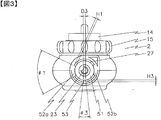
- FIG. 2 is a longitudinal sectional view showing only a main body for a water purifier.
- the water purifier 1 includes a water purifier main body 2 having a switching valve built therein and a water purifier cartridge 3 in which a filter medium is accommodated.
- the water purifier main body 2 is provided with a lever-11, and by operating the lever-11, tap water (raw water) flowing from the tap tap 4 is discharged as shower water as it is (raw water shower).
- tap water raw water flowing from the tap tap 4
- shower water as it is (raw water shower).
- -It can be switched by selecting whether it is discharged as raw water (raw water straight) or supplied to the water purifier cartridge 3.
- the raw water supplied to the water purifier cartridge 3 is filtered by an adsorbent such as activated carbon and a hollow fiber membrane, and is discharged as purified water from a water purification port.
- a ring-shaped packing 13 is attached to the switching valve body 12 provided in the water purifier body 2, and a mounting nut 15 is screwed into the switching valve body 12 via an adapter 14 screwed into the male thread portion of the water tap 4.
- the water purifier main body 2 is attached to the water tap 4.
- the interior of the switching valve main body 12 is divided into an upper chamber 18 and a lower chamber 19 by a partition plate 17 having three water passages 16a, 16b, and 16c.
- a partition plate 17 having three water passages 16a, 16b, and 16c.
- three balls (valves) 20a, 20b, and 20c are arranged so as to correspond to the three water passages 16a, 16b, and 16c.
- the lower end of the ball 20a protrudes into the lower chamber 19 in a state where the ball 20a is fitted in the water passage 16a and the water passage 16a is closed.
- a valve shaft 21 is rotatably inserted, and O-rings 22 a, 22 b, 22 c disposed at predetermined positions of the valve shaft 21 are watertight with the inner wall surface of the lower chamber 19. Is engaged.
- the lower chamber 19 is divided into three sections, a flow path 24a leading from the water flow path 16a to the raw water supply port 23 for supplying tap water to the water purifier cartridge 3, and a flow leading from the water flow path 16b to the raw water straight port 28.
- a channel 24b and a channel 24c that leads from the water channel 16c to the raw water shower port 25 are formed.
- the valve shaft 21 is provided with cam portions 26a, 26b, and 26c at positions facing the water passages 16a, 16b, and 16c. These cam portions 26a, 26b, and 26c can selectively face upward by rotating the valve shaft 21 by 90 °, for example, and push up the lower end of the ball protruding into the lower chamber 19 to open the water passage. It can be done. That is, by rotating the valve shaft 21 by a predetermined angle, one of the water passages 16a, 16b, and 16c is opened, and the raw water flowing in from the water tap 4 is discharged as shower water as it is, or straight water as it is. Can be discharged or supplied to the water purifier cartridge 3.
- a substantially circular hole-shaped raw water supply unit 27 that supplies raw water to the water purifier cartridge 3 is provided.
- the raw water supply unit 27 and the raw water receiving unit 32 of the water purifier cartridge 3 are configured to be detachable by a bayonet mechanism. Details of the raw water supply unit 27 will be described later.
- the water purifier cartridge 3 is provided with a substantially cylindrical raw water receiving portion 32 at the side of the container 31. Details of the raw water receiving unit 32 will be described later.
- a plurality of shower holes (water purification ports) 33 for filtering the raw water and discharging it as purified water are provided at the lower part of the container 31.
- the raw water supply unit 27 is described as having a substantially circular hole shape, and the raw water receiving unit 32 is described as having a substantially cylindrical shape.
- the raw water supply unit 27 has a substantially cylindrical shape, and the raw water receiving unit 32 has a substantially circular hole shape. It may be a form.
- a cylindrical projection 31a formed on the inner bottom surface of the container 31 has a lower end of a cylindrical case 34 fitted and erected via an O-ring 35.
- the upper and lower outer peripheral surfaces of the cylindrical case 34 are ring-shaped filters 36 and 37.
- 31 is fixed to the inner wall surface.
- a hollow fiber membrane bundle 38 in which a plurality of hollow fiber membranes are bundled and folded and stored in an inverted U shape is disposed. Both ends of the hollow fiber membrane are sealed and fixed by mixing and filling a gap between the hollow fibers at the lower part of the cylindrical case 34 and a two-component curable resin 39 as a sealing agent between the hollow fiber and the cylindrical case 34. (Potting).
- each hollow fiber is opened toward the water purification port 33.
- An adsorbent 40 made of activated carbon, zeolite, ion exchange resin, chelate resin or the like is disposed between the cylindrical case 34 and the inner wall surface of the container 31.
- the upper part of the container 31 is opened so that the hollow fiber membrane bundle 38 and the adsorbent 40 can be easily filled, and a transparent cap 41 is fitted so that the hollow fiber can be clearly seen from the outside.
- a lid 42 is provided on the upper portion of the transparent cap 41 so as to be detachable from the container 31.
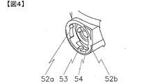
- FIG. 3 is a left side view showing an example of the water purifier main body in the present invention
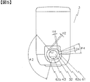
- FIG. 4 is an enlarged perspective view of the vicinity of the raw water supply portion of the water purifier main body.
- the raw water supply unit 27 has a substantially circular hole shape, and a raw water supply port 23 is arranged in the inside thereof, and a ring-shaped connection portion packing 51 is attached so as to surround the raw water supply port 23.
- first convex parts 52a and 52b protrudes inward.
- the first convex portions 52a and 52b are centrally symmetric.
- the center-symmetric shape has a good balance in strength, but it does not have to be the center target shape.
- the angle ⁇ 1 of the first convex portions 52a and 52b is preferably 30 to 150 degrees.
- the height H1 from the viewpoint of keeping the strength of the first convex portion high and the outer diameter of the raw water receiving portion 32 described later, the height H1 from the viewpoint of keeping the cross-sectional area of the raw water receiving port 43 large and ensuring the flow rate. Is preferably 5 to 20% of the inner diameter of the circular hole shape. In addition, the thickness of the 1st convex parts 52a and 52b is constant.
- a third convex portion 53 is disposed at an intermediate position between the first convex portions 52a and 52b in the inner circumference of the substantially circular hole-shaped raw water supply portion 27. From the viewpoints of keeping the strength of the third convex portion high, keeping the notch 61 described later small and keeping the strength of the second convex portion 62a high, and keeping the cross-sectional area of the raw water inlet 43 large and ensuring the flow rate.
- the angle ⁇ 3 of the third convex portion 53 is preferably 5 to 30 degrees, the width D3 is preferably 1 to 5 mm, and the height H3 is preferably 1 to 4 mm.
- FIG. 4 shows an example in which the back side of the first protrusions 52a and 52b is released by the inner slide method, and the back side of the third protrusion is provided with an opening 54 to release the mold.
- it is not limited to this combination.
- connection portion packing 51 silicone rubber, ethylene propylene rubber, nitrile rubber, or the like is used.
- a rubber having a JIS A hardness of 30 to 80 degrees is used, but it is preferably 45 to 60 degrees in consideration of pressure resistance and a load on the resin member. It is more preferable that the first convex portions 52a and 52b have hooks so that they do not fall off even when subjected to vibration or impact.
- FIG. 5 is a right side view showing an example of the water purifier cartridge in the present invention
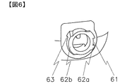
- FIG. 6 is an enlarged perspective view of the vicinity of the raw water receiving port of the water purifier cartridge.
- the raw water receiving part 32 has a substantially cylindrical shape, and a raw water receiving port 43 is arranged inside thereof.
- the second convex portions 62a and 62b protrude outward.
- the second convex portions 62a and 62b have a centrally symmetric shape.
- the center-symmetric shape has a good balance in strength, but it does not have to be the center target shape. From the viewpoints of keeping the strength of the second convex portion high, keeping the strength of the first convex portion high, keeping the outer diameter of the raw water receiving portion 32 small, and keeping the water purifier main body 2 small.
- the angles ⁇ 2 of the convex portions 62a and 62b are preferably 30 to 150 degrees, and the height H2 is preferably 5 to 20% of the outer diameter of the cylindrical shape.
- a stopper 63 is provided on the back side of the second convex portion 62b, that is, on the side away from the cylindrical end surface.
- the second protrusions 62a and 62b are thin at one end and gradually thickened, and the other end is constant in thickness.
- a notch 61 is provided at an intermediate position of the second convex portion 62a. From the standpoint of keeping the strength of the third convex portion high and keeping the strength of the second convex portion 62a high, the angle ⁇ 4 of the notch 61 is 5 to 30 degrees, the width D4 is 1 to 5 mm, the depth The length H4 is preferably 1 to 4 mm.
- the water purifier cartridge 3 is leveled and the raw water receiving portion 32 is inserted into the raw water supply portion 27 of the water purifier main body 2.
- the pair of first convex portions 52a and 52b provided in the raw water supply portion 27 and the pair of second convex portions 62a and 62b provided in the raw water receiving portion can be inserted without interference.
- natural water supply part 27 passes the notch 61 provided in the 2nd convex part 62a. If the insertion angle is wrong by 180 degrees, the third convex portion 53 cannot be inserted because it hits the second convex portion 62b not provided with a notch. That is, the user can be made aware that the insertion angle is wrong.
- each ⁇ 1 and The total of each ⁇ 2 may not exceed 360 degrees.
- the play angle in the rotational direction when the first convex portions 52a and 52b and the second convex portions 62a and 62b are inserted without interference is made smaller than the angle between the first convex portion and the third convex portion.
- the first convex portion 52b provided in the raw water supply portion 27 comes into contact with the stopper 63 provided in the raw water receiving portion 32.
- the first convex portions 52a and 52b are brought into contact with the second convex portion provided in the current water receiving portion and receive the repulsive force due to the packing 51 being crushed.
- the water purifier cartridge 3 stands upright, and the shower hole (water purification port) 33 faces downward.
- the water purifier cartridge 3 can be attached to the water purifier main body 2 only by these two steps, and there is no need to rotate the cap or the water purifier cartridge many times. There is no need to increase one member in order to fix the water purifier cartridge 3. The type of cartridge in use can be confirmed when purchasing spare parts. There is no possibility that the water will be upwardly attached with a wrong angle of 180 degrees.
- the tap water flows into the water purifier cartridge 3 and first comes into contact with the adsorbent 40 to decompose free residual chlorine in the tap water, and at the same time volatilizes in the tap water. Organic matter is adsorbed and removed. Next, the water reaches the hollow fiber membrane bundle 38 inside the adsorbent 40. Water flows from the outer diameter side to the inner diameter side of the hollow fiber membrane, and turbidity and bacteria in the water are captured by the hollow fiber membrane. The purified water that has passed through the hollow fiber membrane is discharged from a shower hole (water purification port) 33. The user can obtain delicious and safe purified water.
- a pair of first protrusions are protruded inward in the vicinity of the opening end face of the circular hole-shaped raw water supply part to form a centrally symmetric shape.
- the angle ⁇ 1 of the first convex portions was 55 degrees each, and the height H1 was constant at 7.5 mm of the inner diameter of the circular hole shape at 3 mm.
- a third convex portion is disposed at an intermediate position between the pair of first convex portions.
- the angle ⁇ 3 of the third convex portion 53 is about 11 degrees, the width D3 is 2 mm, and the height H3 is 1.5 mm.
- a pair of second protrusions are projected outward in the vicinity of the opening end face of the cylindrical raw water supply unit to form a centrally symmetric shape.
- the angle ⁇ 2 of the second protrusions is 125 degrees each, and the height H2 is 8.8% of the outer diameter of the cylinder.
- a stopper is provided on the back side of the pair of second protrusions, that is, on the side away from the cylindrical end face. Was provided.
- the end of the second convex portion was thin and gradually thickened, and the thickness close to the stopper was made constant at 3 mm.
- a notch is provided at an intermediate position of one second convex portion, the angle ⁇ 4 of the notch 61 is about 11 degrees, the width D4 is 2.5 mm, and the depth H4 is 1.5 mm.
- the water purifier cartridge was leveled and the raw water receiving portion was inserted into the raw water supply portion of the water purifier main body.
- the pair of first protrusions and the pair of second protrusions could be inserted without interference, and the third protrusion passed through the notch provided in the second protrusion.
- the water purifier cartridge is rotated 90 degrees clockwise as the second step, the first convex portion provided in the raw water supply portion comes into contact with the stopper provided in the raw water receiving portion, and the second convex provided in the raw water receiving portion. It also contacted the part.
- the cartridge for the water purifier stood upright and the shower hole (water purification port) turned straight down.
- the water purifier cartridge was successfully connected to the water purifier body.
- ⁇ Comparative Example 1> A pair of first protrusions are projected inward in the vicinity of the opening end face of the circular hole-shaped raw water supply unit 27 to form a centrally symmetric shape.
- the angle ⁇ 1 of the first convex portions was 55 degrees each, and the height H1 was constant at 7.5 mm of the inner diameter of the circular hole shape at 3 mm.
- the 3rd convex part was not arranged in the middle position of a pair of 1st convex parts.
- a pair of second protrusions are projected outward in the vicinity of the opening end face of the cylindrical raw water supply unit 43 to form a centrally symmetric shape.
- the angle ⁇ 2 of the second convex portions is 125 degrees, and the height H2 is 8.8% of the cylindrical outer diameter.
- a stopper was provided. The end of the second convex portion was thin and gradually thickened, and the thickness close to the stopper was made constant at 3 mm. The second convex part was not provided with a notch.
- the water purifier cartridge was connected to the water purifier body.
- the water purifier cartridge was leveled, and the raw water receiving portion was inserted into the raw water supply port of the water purifier main body.
- the pair of first protrusions and the pair of second protrusions could be inserted without interference.
- the water purifier cartridge is rotated 90 degrees clockwise as the second step, the first convex portion provided in the raw water supply portion comes into contact with the stopper provided in the raw water receiving portion, and the second convex provided in the raw water receiving portion. It also contacted the part.
- the water purifier cartridge was upright, but the shower hole (water purification port) faced directly above. I didn't realize that I could't connect successfully until the end.
- the present invention can be applied to water purifiers in general such as a faucet-directly connected water purifier, a stationary water purifier, and an undersink water purifier, but is not limited thereto.
Landscapes
- Life Sciences & Earth Sciences (AREA)
- Hydrology & Water Resources (AREA)
- Engineering & Computer Science (AREA)
- Environmental & Geological Engineering (AREA)
- Water Supply & Treatment (AREA)
- Chemical & Material Sciences (AREA)
- Organic Chemistry (AREA)
- Water Treatment By Sorption (AREA)
Abstract
本発明は、容易かつ確実に浄水器用カートリッジが着脱できる浄水器である。原水供給部を備えた浄水器本体と、浄水器本体に接続し、原水受入部を備えた浄水器用カートリッジから成り、原水供給部と原水受入部のいずれか一方が略円穴形部であり、他方が略円筒形部であり、略円穴形部の内周に一対の第1凸部を有し、略円筒形部の外周に一対の第2凸部を有し、略円筒形部を略円穴形部に挿入して回転させることで、第1凸部と第2凸部が係合して接続状態を保ち、一対の第2凸部の一方に切り欠きを有し、一対の第1凸部の間にひとつの第3凸部を有し、挿入時に第3凸部が切り欠きを通過することを特徴とする。
Description
本発明は、水道水を浄化する浄水器および浄水器用カートリッジに関し、さらに詳しくは、浄水器用本体に浄水器用カートリッジを着脱する浄水器および浄水器用カートリッジに関するものである。
従来、水道水を浄化する浄水器としては、水道水栓の吐出口に直結する蛇口直結型浄水器や、シンクの上に置いて使用する据置型浄水器などが知られている。いずれも水道水を濾過する流路と、濾過せずそのまま水道水を吐出させる流路に切り換える切換弁を備え、水道水を濾過する流路に着脱可能な浄水器用カートリッジを取り付けて使用する。浄水器用カートリッジに充填した濾材は処理できる総ろ過水量が限られているため、飲用など浄水を得たいときにだけ浄水器用カートリッジを取り付けた流路を選択し、バケツに水を汲むときなどには水道水を吐出させる流路を選択することで、浄水器用カートリッジを長期間使えるようにしている。
浄水器用カートリッジの着脱方法としては、例えば特許文献1のように、浄水器用カートリッジの原水受入口(特許文献1では原水流入口22a)を浄水器用本体の原水供給口(特許文献1では原水流出口7a)に接続してから、別部材であるキャップを浄水器用カートリッジに被せて、ケーシング(特許文献1では上ケース3と下ケース2)に嵌合させる方法がある。しかしながら、キャップのねじを何回も回転させるのには手間がかかるという問題点があった。また、浄水器用カートリッジを着脱するために1部材増えるため、製造原価が上がるという問題点があった。さらに、浄水器用カートリッジが外から見えなくなるため、予備品を購入しようとしても種類が確認できないという問題点があった。
これに対して、例えば特許文献2のような、浄水器用本体に螺旋おねじを、浄水器用カートリッジに螺旋めねじを設けて、螺合させて嵌め止める方法であれば、固定するために1部材増やす必要が無い。予備品を購入する際にも使用中のカートリッジの種類を確認できる。しかしながら、何回も回転させるという手間がかかるという問題点は解決できていない。
これに対して、特許文献3には、浄水器用本体(特許文献3ではボディ)と浄水器用カートリッジとをバヨネット機構により接続する方法が提案されている。第1ステップとして浄水器用カートリッジを水平にして、その原水受入口を浄水器本体の原水供給口に挿入し、第2ステップとして時計方向に90度回動させる。この2ステップのみで浄水器用本体に浄水器用カートリッジを取り付けることができ、キャップや浄水器用カートリッジを何回も回転させる必要は無い。浄水器用カートリッジを固定するために1部材増やす必要も無い。予備品を購入する際にも使用中のカートリッジの種類を確認できる。しかしながら、浄水器用カートリッジの原水受入口に設けた一対の凸部が対称形状であるため、180度間違えて取り付けて、浄水が上向きに出てしまうという問題点があった。特許文献3には、凸部が一対ではなく二対以上であっても良いと記載されているが、角度を間違えて取り付けてしまう可能性が増えてしまうという問題点があった。
本発明は、従来の技術における上記の問題点に鑑み、浄水器本体に浄水器用カートリッジを着脱するために1部材増えて製造原価が上がることが無く、浄水器用カートリッジを何回も回す手間がかからず、予備品を購入する際に使用中のカートリッジの種類を確認でき、角度を間違えて取り付けて浄水が上向きに出てしまうことが無い、容易かつ確実に浄水器用カートリッジが着脱できる浄水器を提供することにある。
上記の目的を達成するため、本発明の浄水器は、原水供給部を備えた浄水器本体と、浄水器本体に接続し、原水受入部を備えた浄水器用カートリッジから成り、原水供給部と原水受入部のいずれか一方が略円穴形部であり、他方が略円筒形部であり、略円穴形部の内周に一対の第1凸部を有し、略円筒形部の外周に一対の第2凸部を有し、略円筒形部を略円穴形部に挿入して回転させることで、第1凸部と第2凸部が係合して接続状態を保ち、一対の第2凸部の一方に切り欠きを有し、一対の第1凸部の間にひとつの第3凸部を有し、挿入時に第3凸部が切り欠きを通過することを特徴とするものである。
ここで、略円筒形部の外周にストッパを有し、略円筒形部を略円穴形部に挿入して回転させると、第1凸部がストッパに当接することが好ましい。
また、本発明の浄水器用カートリッジは、原水受入部を備えた浄水器用カートリッジであり、原水受入部が略円筒形であり、原水受入部の外周に一対の第2凸部を有し、第2凸部の一方に切り欠きを有することを特徴とするものである。
本発明によれば、原水供給部を備えた浄水器本体と、浄水器本体に接続し、原水受入部を備えた浄水器用カートリッジから成り、原水供給部と原水受入部のいずれか一方が略円穴形部であり、他方が略円筒形部であり、略円穴形部の内周に一対の第1凸部を有し、略円筒形部の外周に一対の第2凸部を有し、略円筒形部を略円穴形部に挿入して回転させることで、第1凸部と第2凸部が係合して接続状態を保ち、一対の第2凸部の一方に切り欠きを有し、一対の第1凸部の間にひとつの第3凸部を有し、挿入時に第3凸部が切り欠きを通過する浄水器なので、浄水器本体に浄水器用カートリッジを着脱するために1部材増えることは無く、製造原価は上がらない。浄水器用カートリッジを着脱する際に、浄水器用カートリッジを何回も回すような手間は要らない。浄水器用カートリッジの予備品を購入する際にも使用中のカートリッジの種類を確認できる。挿入時に第3凸部が切り欠きを通過するようになっているので、角度を間違えて取り付けて浄水が上向きに出てしまうことは無い。
略円筒形部の外周にストッパを有し、略円筒形部を略円穴形部に挿入して回転させると、第1凸部がストッパに当接するようになっていれば、浄水器用カートリッジが所定の角度で停止して、最も使い易い角度に固定できる。
原水受入部を備えた浄水器用カートリッジであり、原水受入部が略円筒形であり、原水受入部の外周に一対の第2凸部を有し、第2凸部の一方に切り欠きを有することを特徴とする浄水器用カートリッジであれば、浄水器用本体に着脱する際に何回も回す手間がかからず、角度を間違えて取り付けて浄水が上向きに出てしまうことも無い。使用中にも種類が確認でき、正しい予備品を購入することができる。
本発明における浄水器の一実施形態を図面に基いて説明する。
図1は、本発明における浄水器の一例を示した縦断面図であり、図2は、浄水器用本体のみ示した縦断面図である。図1に示すように、この浄水器1はその内部に切換弁を内蔵した浄水器用本体2と、濾材が収納された浄水器用カートリッジ3とから構成されている。浄水器用本体2にはレバ-11が設けられ、レバ-11を操作することにより、水道蛇口4から流入した水道水(原水)をそのままシャワ-水として吐出するか(原水シャワ-)、そのままストレ-ト水として吐出するか(原水ストレ-ト)、浄水器用カートリッジ3に供給するか、を選択して切り換えられる。浄水器用カートリッジ3に供給された原水は、活性炭などの吸着材と中空糸膜によって濾過され、浄水口から浄水として吐出される。
浄水器本体2に設けた切換弁本体12には、リング状のパッキン13が装着され、水道蛇口4のおねじ部分にねじ込んだアダプタ14を介して、取付ナット15を切換弁本体12にねじ込むことにより、浄水器用本体2が水道蛇口4に取り付けられるようになっている。
図2に示すように、切換弁本体12の内部は、3個の通水路16a、16b、16cを開設した区画板17によって、上部室18と下部室19とに区画されている。上部室18には、3個のボ-ル(弁体)20a、20b、20cが、3個の通水路16a、16b、16cに対応するように配置されている。ボ-ル20aが通水路16aにはまり通水路16aが閉じた状態で、ボ-ル20aの下端部が下部室19に突出するようになっている。ボ-ル16b、16cについても同様である。 円筒状の下部室19には、弁軸21が回転可能に挿着され、かつ弁軸21の所定位置に配設したOリング22a、22b、22cが、下部室19の内壁面と水密的に係合している。これによって下部室19は3つに区画され、通水路16aから浄水器用カートリッジ3に水道水を供給する原水供給口23へ通じる流路24aと、通水路16bから原水ストレ-ト口28へ通じる流路24bと、通水路16cから原水シャワ-口25へ通じる流路24cとを形成している。弁軸21には、通水路16a、16b、16cに対向する位置に、カム部26a、26b、26cが設けられている。これらカム部26a、26b、26cは、弁軸21を例えば90゜ずつ回転させることにより選択的に上方を向き、下部室19に突出したボ-ルの下端部を押し上げて通水路を開くことができるようになっている。すなわち、弁軸21を所定角度回動することで、通水路16a、16b、16cのいずれかを開放し、水道蛇口4から流入した原水をそのままシャワ-水として吐出するか、そのままストレ-ト水として吐出するか、浄水器用カートリッジ3に供給するか、を選択できる。
浄水器用本体2の側部には、浄水器用カートリッジ3に原水を供給する、略円穴形の原水供給部27が設けられている。原水供給部27と、浄水器用カートリッジ3の原水受入部32は、バヨネット機構により着脱が可能に構成されている。原水供給部27の詳細については後述する。
次に、浄水器用カートリッジ3について説明する。浄水器用カートリッジ3は、その容器31の側部に、略円筒形の原水受入部32が設けられている。原水受入部32の詳細については後述する。容器31の下部には、原水を濾過して浄化水として吐出する複数のシャワ-孔(浄水口)33が設けられている。
なお、ここでは、原水供給部27が略円穴形、原水受入部32が略円筒形の形態を説明しているが、原水供給部27が略円筒形、原水受入部32が略円穴形の形態であっても良い。
容器31の内部底面に形成された円筒状突起31aには円筒ケース34の下端がOリング35を介して嵌入立設され、この円筒ケース34上下端外周面がリング状のフィルタ36、37で容器31の内壁面に固定されている。円筒ケース34の内部には、複数本の中空糸膜を束ねて逆U字状に折り曲げて収納した中空糸膜束38が配備されている。中空糸膜の両端末は、円筒ケース34の下部にて各中空糸間の隙間および中空糸と円筒ケース34の間に封止剤としての二液硬化型樹脂39を混合充填して封止固定(ポッティング)されている。容器31へ嵌入する前にポッティング部を一部切断除去しているので、各中空糸の末端は浄水口33に向かって開口している。円筒ケース34と容器31の内壁面との間には活性炭、ゼオライト、イオン交換樹脂、キレ-ト樹脂などからなる吸着材40が配備されている。また、容器31の上部は、中空糸膜束38と吸着材40が容易に充填できるよう開口しており、中空糸の汚れ具合が外部からよく見えるように透明キャップ41が嵌入されている。さらに透明キャップ41の上部には蓋42が容器31と着脱自在に設けられている。
次に浄水器用本体2の原水供給部27について説明する。図3は、本発明における浄水器用本体の一例を示した左側面図であり、図4は、浄水器用本体の原水供給部の近傍を拡大した斜視図である。
原水供給部27は略円穴形であり、その内部には原水供給口23が配され、原水供給口23を囲むようにリング状の接続部パッキン51が装着されている。
円穴形の原水供給部27の開口端面近傍には、一対の第1凸部52a、52bが内側に向かって突出している。第1凸部52aと52bは中心対称形状である。ただし、中心対称形状であると強度的にバランスが良いが、必ずしも中心対象形状でなくても良い。また、第1凸部の強度を高く保つこと、後述の第2凸部の強度を高く保つことなどの観点から、第1凸部52a、52bの角度θ1は各々30~150度が好ましい。また、第1凸部の強度を高く保つこと、後述の原水受入部32の外径との兼ね合いにおいて、原水受入口43の断面積を大きく保ち流量を確保することなどの観点から、高さH1は、円穴形の内径の5~20%が好ましい。なお、第1凸部52aと52bの厚さは一定である。
略円穴形の原水供給部27の内周における、第1凸部52a、52bの中間位置には第3凸部53を配設している。第3凸部の強度を高く保つこと、後述の切り欠き61を小さく保ち第2凸部62aの強度を高く保つこと、原水受入口43の断面積を大きく保ち流量を確保することなどの観点から、第3凸部53の角度θ3は5~30度、幅D3としては1~5mm、高さH3は1~4mmが好ましい。
原水供給部27を射出成形により大量生産する場合、第1凸部52a、52bと第3凸部53は、そのアンダーカット部を内スライド方式で離型するか、あるいはアンダーカット部の外周を開口させて離型する。図4には、第1凸部52a、52bの奥側を内スライド方式で離型させ、第3凸部の奥側は開口54を設けて離型させる一例を示した。ただし、この組み合わせに限定されない。
接続部パッキン51には、シリコーンゴム、エチレンプロピレンゴム、ニトリルゴムなどが用いられる。JIS A硬度30~80度のゴムが用いられるが、耐圧性と樹脂部材への負荷などを勘案すると45~60度が好ましい。振動や衝撃が与えられても脱落しないように、第1凸部52a、52bに引っ掛かる鍔が付いていれば、さらに好ましい。
次に浄水器用カートリッジ3の原水受入部32について説明する。
図5は、本発明における浄水器用カートリッジの一例を示した右側面図であり、図6は、浄水器用カートリッジの原水受入口の近傍を拡大した斜視図である。
原水受入部32は略円筒形であり、その内部には原水受入口43が配されている。
円筒形の原水受入部32の開口端面近傍には、一対の第2凸部62a、62bが外側に向かって突出している。第2凸部62aと62bは中心対称形状である。ただし、中心対称形状であると強度的にバランスが良いが、必ずしも中心対象形状でなくても良い。第2凸部の強度を高く保つこと、前述の第1凸部の強度を高く保つこと、原水受入部32の外径を小さく保ち浄水器本体2を小型に保つことなどの観点から、第2凸部62a、62bの角度θ2は各々30~150度、高さH2が円筒形の外径の5~20%が好ましい。
第2凸部62bの奥側、すなわち円筒形の端面から離れる側にストッパ63が設けられている。略円筒形の原水受入部32を略円穴形の原水供給部27に挿入して回転させると、原水供給部27に設けた第1凸部52bがストッパ63に当接する。このときに浄水器用カートリッジ3が直立し、シャワ-孔(浄水口)33が真下を向くようになっている。
第2凸部62a、62bは一端が薄く、徐々に厚くし、他端は厚みを一定にしている。略円筒形の原水受入部32を略円穴形の原水供給部27に挿入して回転させると、第2凸部62a、62bの厚みの変化により浄水器用カートリッジ3が浄水器用本体に近付くようになっている。同時に接続用パッキン51のつぶししろが大きくなり、原水供給口23と原水受入口43を液密に保つことができる。
第2凸部62aの中間位置には切り欠き61が設けられている。前述の第3凸部の強度を高く保つこと、第2凸部62aの強度を高く保つことなどの観点から、切り欠き61の角度θ4は5~30度、幅D4としては1~5mm、深さH4は1~4mmが好ましい。
上記のような構成を有する浄水器1において、浄水器用本体2に浄水器用カートリッジ3を接続する方法について説明する。第1ステップとして浄水器用カートリッジ3を水平にして、その原水受入部32を浄水器用本体2の原水供給部27に挿入する。このとき原水供給部27に設けた一対の第1凸部52a、52bと、原水受入部に設けた一対の第2凸部62a、62bが干渉せずに挿入できるようになっている。同時に原水供給部27に設けた第3凸部53が、第2凸部62aに設けた切り欠き61を通過する。ここで挿入する角度を180度間違えたとすると、第3凸部53が、切り欠きが設けられていない第2凸部62bに当たって挿入できない。すなわち、使用者に挿入する角度を間違えたことを気付かせることができる。
第1凸部52a、52bの角度θ1が各々異なる場合や、第2凸部62a、62bの角度θ2が各々異なる場合であっても、前述のθ1とθ2の好ましい範囲を保ちながら、各θ1と、各θ2の合計が360度を超えないようにすれば良い。第1凸部52a、52bと、第2凸部62a、62bが干渉せずに挿入するときの回転方向の遊び角を、第1凸部と第3凸部との間の角よりも小さくすることにより、同様の効果を得ることができる。
第2ステップとして浄水器用カートリッジ3を時計方向に90度回動させると、原水供給部27に設けた第1凸部52bが、原水受入部32に設けたストッパ63に当接する。同時に、第1凸部52a、52bが、現水受入部に設けた第2凸部に当設し、パッキン51がつぶされたことによる反発力を受け止める。このときに浄水器用カートリッジ3が直立し、シャワ-孔(浄水口)33が真下を向くようになっている。
この2ステップのみで浄水器用本体2に浄水器用カートリッジ3を取り付けることができ、キャップや浄水器用カートリッジを何回も回転させる必要は無い。浄水器用カートリッジ3を固定するために1部材増やす必要は無い。予備品を購入する際にも使用中のカートリッジの種類を確認できる。角度を180度間違えて取り付けて浄水が上向きに出てしまうことも無い。
流路切換弁を浄水状態にして水栓を開くと、水道水は浄水器用カートリッジ3に流入し、まず吸着材40と接触して、水道水中の遊離残留塩素が分解され、同時に水道水中の揮発性有機物が吸着除去される。次に水は吸着材40の内部の中空糸膜束38に到達する。水は中空糸膜の外径側から内径側に流れ、水中の濁質や細菌が中空糸膜に捕捉される。中空糸膜を通過した浄水はシャワ-孔(浄水口)33から吐出される。使用者は美味しくて安全な浄水を得ることができる。
<実施例1>
円穴形の原水供給部の開口端面近傍に一対の第1凸部を内側に向かって突出させ、中心対称形状とした。第1凸部の角度θ1を各々55度、高さH1を円穴形の内径の7.5%厚さは3mmで一定とした。一対の第1凸部の中間位置には第3凸部を配設し、第3凸部53の角度θ3は約11度、幅D3は2mm、高さH3は1.5mmとした。
円穴形の原水供給部の開口端面近傍に一対の第1凸部を内側に向かって突出させ、中心対称形状とした。第1凸部の角度θ1を各々55度、高さH1を円穴形の内径の7.5%厚さは3mmで一定とした。一対の第1凸部の中間位置には第3凸部を配設し、第3凸部53の角度θ3は約11度、幅D3は2mm、高さH3は1.5mmとした。
円筒形の原水供給部の開口端面近傍に一対の第2凸部を外側に向かって突出させ、中心対称形状とした。第2凸部の角度θ2は各々125度、高さH2を円筒形の外径の8.8%とした、一対の第2凸部の奥側、すなわち円筒形の端面から離れる側にはストッパを設けた。第2凸部は端部が薄く、徐々に厚くし、ストッパに近い部分は厚みを3mmで一定にした。一方の第2凸部の中間位置に切り欠きを設け、切り欠き61の角度θ4は約11度、幅D4としては2.5mm、深さH4は1.5mmとした。
浄水器用本体に浄水器用カートリッジを接続した状況を説明する。第1ステップとして浄水器用カートリッジを水平にして、その原水受入部を浄水器用本体の原水供給部に挿入した。このとき一対の第1凸部と、一対の第2凸部は干渉せずに挿入でき、第3凸部が、第2凸部に設けた切り欠きを通過した。第2ステップとして浄水器用カートリッジを時計方向に90度回動させると、原水供給部に設けた第1凸部が、原水受入部に設けたストッパに当接し、原水受入部に設けた第2凸部にも当接した。浄水器用カートリッジが直立して、シャワ-孔(浄水口)が真下を向いた。浄水器用本体に浄水器用カートリッジを正常に接続できた。
<比較例1>
円穴形の原水供給部27の開口端面近傍に一対の第1凸部を内側に向かって突出させ、中心対称形状とした。第1凸部の角度θ1を各々55度、高さH1を円穴形の内径の7.5%厚さは3mmで一定とした。一対の第1凸部の中間位置に第3凸部は配設しなかった。
<比較例1>
円穴形の原水供給部27の開口端面近傍に一対の第1凸部を内側に向かって突出させ、中心対称形状とした。第1凸部の角度θ1を各々55度、高さH1を円穴形の内径の7.5%厚さは3mmで一定とした。一対の第1凸部の中間位置に第3凸部は配設しなかった。
円筒形の原水供給部43の開口端面近傍に一対の第2凸部を外側に向かって突出させ、中心対称形状とした。第2凸部の角度θ2は各々125度、高さH2を円筒形の外径の8.8%とした、一対の第2凸部の奥側、すなわち円筒形の端面から離れる側には一対のストッパを設けた。第2凸部は端部が薄く、徐々に厚くし、ストッパに近い部分は厚みを3mmで一定にした。第2凸部には切り欠きを設けなかった。
浄水器用本体に浄水器用カートリッジを接続した状況を説明する。第1ステップとして浄水器用カートリッジを水平にして、その原水受入部を浄水器用本体の原水供給口に挿入した。このとき一対の第1凸部と、一対の第2凸部は干渉せずに挿入できた。第2ステップとして浄水器用カートリッジを時計方向に90度回動させると、原水供給部に設けた第1凸部が、原水受入部に設けたストッパに当接し、原水受入部に設けた第2凸部にも当接した。浄水器用カートリッジは直立したが、シャワ-孔(浄水口)は真上を向いた。最後まで正常に接続できなかったことに気が付かなかった。
本発明は、蛇口直結型浄水器、据置型浄水器、アンダーシンク型浄水器など浄水器全般に応用できるが、これらに限定されるものではない。
1 浄水器
2 浄水器用本体
3 浄水器用カートリッジ
4 水道蛇口
11 レバー
12 切換弁本体
13 パッキン
14 アダプタ
15 取付ナット
16a 通水路
16b 通水路
16c 通水路
17 区画板
18 上部室
19 下部室
20a ボール
20b ボール
20c ボール
21 弁軸
22a Oリング
22b Oリング
22c Oリング
23 原水供給口
24a 流路
24b 流路
24c 流路
25 原水シャワー口
26a カム部
26b カム部
26c カム部
27 原水供給部
28 原水ストレート口
31 容器
31a 円筒状突起
32 原水受入部
33 シャワー孔(浄水口)
34 円筒ケース
35 Oリング
36 フィルタ
37 フィルタ
38 中空糸膜束
39 二液硬化型樹脂
40 吸着材
41 透明キャップ
42 蓋
43 原水受入口
51 接続用パッキン
52a 第1凸部
52b 第1凸部
53 第3凸部
54 開口
61 切り欠き
62a 第2凸部
62b 第2凸部
63 ストッパ
2 浄水器用本体
3 浄水器用カートリッジ
4 水道蛇口
11 レバー
12 切換弁本体
13 パッキン
14 アダプタ
15 取付ナット
16a 通水路
16b 通水路
16c 通水路
17 区画板
18 上部室
19 下部室
20a ボール
20b ボール
20c ボール
21 弁軸
22a Oリング
22b Oリング
22c Oリング
23 原水供給口
24a 流路
24b 流路
24c 流路
25 原水シャワー口
26a カム部
26b カム部
26c カム部
27 原水供給部
28 原水ストレート口
31 容器
31a 円筒状突起
32 原水受入部
33 シャワー孔(浄水口)
34 円筒ケース
35 Oリング
36 フィルタ
37 フィルタ
38 中空糸膜束
39 二液硬化型樹脂
40 吸着材
41 透明キャップ
42 蓋
43 原水受入口
51 接続用パッキン
52a 第1凸部
52b 第1凸部
53 第3凸部
54 開口
61 切り欠き
62a 第2凸部
62b 第2凸部
63 ストッパ
Claims (3)
- 原水供給部を備えた浄水器本体と、前記浄水器本体に接続し、原水受入部を備えた浄水器用カートリッジからなる浄水器であって、前記原水供給部と前記原水受入部のいずれか一方が略円穴形部であり、他方が略円筒形部であり、前記略円穴形部の内周に一対の第1凸部を有し、前記略円筒形部の外周に一対の第2凸部を有し、前記略円筒形部を前記略円穴形部に挿入して回転させることで、前記第1凸部と前記第2凸部が係合して接続状態を保ち、前記一対の第2凸部の一方に切り欠きを有し、前記一対の第1凸部の間にひとつの第3凸部を有し、挿入時に前記第3凸部が切り欠きを通過することを特徴とする浄水器。
- 前記略円筒形部の外周にストッパを有し、前記略円筒形部を前記略円穴形部に挿入して回転させると、前記第1凸部がストッパに当接することを特徴とする請求項1に記載の浄水器。
- 原水受入部を備えた浄水器用カートリッジであって、原水受入部が略円筒形であり、原水受入部の外周に一対の第2凸部を有し、第2凸部の一方に切り欠きを有することを特徴とする浄水器用カートリッジ。
Priority Applications (1)
| Application Number | Priority Date | Filing Date | Title |
|---|---|---|---|
| CN201480057556.2A CN105916818A (zh) | 2013-11-12 | 2014-04-10 | 净水器以及净水器用滤芯 |
Applications Claiming Priority (2)
| Application Number | Priority Date | Filing Date | Title |
|---|---|---|---|
| JP2013-233664 | 2013-11-12 | ||
| JP2013233664 | 2013-11-12 |
Publications (1)
| Publication Number | Publication Date |
|---|---|
| WO2015072161A1 true WO2015072161A1 (ja) | 2015-05-21 |
Family
ID=53057109
Family Applications (1)
| Application Number | Title | Priority Date | Filing Date |
|---|---|---|---|
| PCT/JP2014/060385 Ceased WO2015072161A1 (ja) | 2013-11-12 | 2014-04-10 | 浄水器および浄水器用カートリッジ |
Country Status (2)
| Country | Link |
|---|---|
| CN (1) | CN105916818A (ja) |
| WO (1) | WO2015072161A1 (ja) |
Citations (3)
| Publication number | Priority date | Publication date | Assignee | Title |
|---|---|---|---|---|
| JPH09136023A (ja) * | 1995-03-07 | 1997-05-27 | Wilhelm A Keller | 多成分カートリッジ又は分配装置に付属品を正しく取付けるための差込式固定装置 |
| JP3303499B2 (ja) * | 1994-01-26 | 2002-07-22 | 東レ株式会社 | 蛇口直結型浄水器 |
| JP2009279559A (ja) * | 2008-05-26 | 2009-12-03 | Mitsubishi Rayon Cleansui Co Ltd | 浄水器 |
Family Cites Families (9)
| Publication number | Priority date | Publication date | Assignee | Title |
|---|---|---|---|---|
| US5989425A (en) * | 1995-11-17 | 1999-11-23 | Toray Industries, Inc. | Multi-way valve and water purifier using the same |
| JPH09253424A (ja) * | 1996-03-19 | 1997-09-30 | Toray Ind Inc | 浄水器 |
| JPH09253636A (ja) * | 1996-03-25 | 1997-09-30 | Toray Ind Inc | 浄水器 |
| JP3941190B2 (ja) * | 1997-10-30 | 2007-07-04 | 東レ株式会社 | 浄水器 |
| CN2781133Y (zh) * | 2005-03-01 | 2006-05-17 | 厦门建霖卫浴工业有限公司 | 水龙头本体与底座的配合结构 |
| JP2013061009A (ja) * | 2011-09-13 | 2013-04-04 | Toray Ind Inc | 浄水器用継手及び据置型浄水器 |
| CN202237517U (zh) * | 2011-09-19 | 2012-05-30 | 珠海格力电器股份有限公司 | 一种滤瓶组件及一种净水装置 |
| JP2013173080A (ja) * | 2012-02-23 | 2013-09-05 | Toray Ind Inc | 浄水カートリッジ及び浄水器 |
| CN202762191U (zh) * | 2012-08-23 | 2013-03-06 | 厦门建霖工业有限公司 | 滤芯安装防呆结构 |
-
2014
- 2014-04-10 WO PCT/JP2014/060385 patent/WO2015072161A1/ja not_active Ceased
- 2014-04-10 CN CN201480057556.2A patent/CN105916818A/zh active Pending
Patent Citations (3)
| Publication number | Priority date | Publication date | Assignee | Title |
|---|---|---|---|---|
| JP3303499B2 (ja) * | 1994-01-26 | 2002-07-22 | 東レ株式会社 | 蛇口直結型浄水器 |
| JPH09136023A (ja) * | 1995-03-07 | 1997-05-27 | Wilhelm A Keller | 多成分カートリッジ又は分配装置に付属品を正しく取付けるための差込式固定装置 |
| JP2009279559A (ja) * | 2008-05-26 | 2009-12-03 | Mitsubishi Rayon Cleansui Co Ltd | 浄水器 |
Also Published As
| Publication number | Publication date |
|---|---|
| CN105916818A (zh) | 2016-08-31 |
Similar Documents
| Publication | Publication Date | Title |
|---|---|---|
| US9878273B2 (en) | Disposable filter cartridge for water dispenser | |
| KR20130000942A (ko) | 정수필터 어셈블리 및 이를 구비한 냉장고 및 정수기 | |
| US20070221561A1 (en) | Liquid filtration systems | |
| JP2010500240A5 (ja) | ||
| CN103702944B (zh) | 净水滤筒以及壶型净水器 | |
| KR101480993B1 (ko) | 정수기 필터용 헤드 조립체 | |
| CN105923800A (zh) | 净水滤筒 | |
| JP5435289B2 (ja) | 浄水装置付き吐水ヘッド及びカバー付き浄化カートリッジ | |
| US9725333B2 (en) | Fluid vessel with removable and reversible filtration unit | |
| JP5578272B2 (ja) | 浄水カートリッジおよび浄水器 | |
| WO2015072161A1 (ja) | 浄水器および浄水器用カートリッジ | |
| WO2013031378A1 (ja) | 液体処理器 | |
| KR20150002961U (ko) | 정수 필터용 커넥터 | |
| KR101165126B1 (ko) | 연수기용 재생통 | |
| KR101306776B1 (ko) | 정수기 필터 조립체 | |
| JP2015093237A (ja) | 浄水器および浄水器用カートリッジ | |
| KR100462231B1 (ko) | 정수기의 필터 장치 | |
| JP2015100770A (ja) | 浄水器 | |
| KR100837391B1 (ko) | 정수기용 파우셋 | |
| JP2015093238A (ja) | 浄水器および浄水器用カートリッジ | |
| KR20170119647A (ko) | 위쪽 방향으로 교체되는 정수장치용 정수필터 | |
| KR100950494B1 (ko) | 정수장치의 필터 장착구조 | |
| KR102557680B1 (ko) | 수전용 필터조립체 | |
| US20260035265A1 (en) | Drinking water pitcher and dispenser with interchangeable cartridges | |
| KR20180137396A (ko) | 정수장치의 필터 결합구조 |
Legal Events
| Date | Code | Title | Description |
|---|---|---|---|
| 121 | Ep: the epo has been informed by wipo that ep was designated in this application |
Ref document number: 14861217 Country of ref document: EP Kind code of ref document: A1 |
|
| NENP | Non-entry into the national phase |
Ref country code: DE |
|
| 122 | Ep: pct application non-entry in european phase |
Ref document number: 14861217 Country of ref document: EP Kind code of ref document: A1 |
|
| NENP | Non-entry into the national phase |
Ref country code: JP |