WO2015072023A1 - システム、通信ノード、および切り替え方法 - Google Patents
システム、通信ノード、および切り替え方法 Download PDFInfo
- Publication number
- WO2015072023A1 WO2015072023A1 PCT/JP2013/080943 JP2013080943W WO2015072023A1 WO 2015072023 A1 WO2015072023 A1 WO 2015072023A1 JP 2013080943 W JP2013080943 W JP 2013080943W WO 2015072023 A1 WO2015072023 A1 WO 2015072023A1
- Authority
- WO
- WIPO (PCT)
- Prior art keywords
- state
- sensor node
- period
- notification signal
- signal
- Prior art date
- Legal status (The legal status is an assumption and is not a legal conclusion. Google has not performed a legal analysis and makes no representation as to the accuracy of the status listed.)
- Ceased
Links
Images








Classifications
-
- H—ELECTRICITY
- H04—ELECTRIC COMMUNICATION TECHNIQUE
- H04L—TRANSMISSION OF DIGITAL INFORMATION, e.g. TELEGRAPHIC COMMUNICATION
- H04L41/00—Arrangements for maintenance, administration or management of data switching networks, e.g. of packet switching networks
- H04L41/06—Management of faults, events, alarms or notifications
- H04L41/0654—Management of faults, events, alarms or notifications using network fault recovery
-
- H—ELECTRICITY
- H04—ELECTRIC COMMUNICATION TECHNIQUE
- H04W—WIRELESS COMMUNICATION NETWORKS
- H04W52/00—Power management, e.g. Transmission Power Control [TPC] or power classes
- H04W52/02—Power saving arrangements
- H04W52/0203—Power saving arrangements in the radio access network or backbone network of wireless communication networks
-
- H—ELECTRICITY
- H04—ELECTRIC COMMUNICATION TECHNIQUE
- H04L—TRANSMISSION OF DIGITAL INFORMATION, e.g. TELEGRAPHIC COMMUNICATION
- H04L41/00—Arrangements for maintenance, administration or management of data switching networks, e.g. of packet switching networks
- H04L41/06—Management of faults, events, alarms or notifications
- H04L41/0604—Management of faults, events, alarms or notifications using filtering, e.g. reduction of information by using priority, element types, position or time
- H04L41/0622—Management of faults, events, alarms or notifications using filtering, e.g. reduction of information by using priority, element types, position or time based on time
-
- H—ELECTRICITY
- H04—ELECTRIC COMMUNICATION TECHNIQUE
- H04L—TRANSMISSION OF DIGITAL INFORMATION, e.g. TELEGRAPHIC COMMUNICATION
- H04L41/00—Arrangements for maintenance, administration or management of data switching networks, e.g. of packet switching networks
- H04L41/06—Management of faults, events, alarms or notifications
- H04L41/0686—Additional information in the notification, e.g. enhancement of specific meta-data
-
- H—ELECTRICITY
- H04—ELECTRIC COMMUNICATION TECHNIQUE
- H04L—TRANSMISSION OF DIGITAL INFORMATION, e.g. TELEGRAPHIC COMMUNICATION
- H04L49/00—Packet switching elements
- H04L49/25—Routing or path finding in a switch fabric
-
- H—ELECTRICITY
- H04—ELECTRIC COMMUNICATION TECHNIQUE
- H04W—WIRELESS COMMUNICATION NETWORKS
- H04W4/00—Services specially adapted for wireless communication networks; Facilities therefor
- H04W4/30—Services specially adapted for particular environments, situations or purposes
- H04W4/40—Services specially adapted for particular environments, situations or purposes for vehicles, e.g. vehicle-to-pedestrians [V2P]
-
- H—ELECTRICITY
- H04—ELECTRIC COMMUNICATION TECHNIQUE
- H04W—WIRELESS COMMUNICATION NETWORKS
- H04W4/00—Services specially adapted for wireless communication networks; Facilities therefor
- H04W4/80—Services using short range communication, e.g. near-field communication [NFC], radio-frequency identification [RFID] or low energy communication
-
- H—ELECTRICITY
- H04—ELECTRIC COMMUNICATION TECHNIQUE
- H04W—WIRELESS COMMUNICATION NETWORKS
- H04W84/00—Network topologies
- H04W84/18—Self-organising networks, e.g. ad-hoc networks or sensor networks
-
- Y—GENERAL TAGGING OF NEW TECHNOLOGICAL DEVELOPMENTS; GENERAL TAGGING OF CROSS-SECTIONAL TECHNOLOGIES SPANNING OVER SEVERAL SECTIONS OF THE IPC; TECHNICAL SUBJECTS COVERED BY FORMER USPC CROSS-REFERENCE ART COLLECTIONS [XRACs] AND DIGESTS
- Y02—TECHNOLOGIES OR APPLICATIONS FOR MITIGATION OR ADAPTATION AGAINST CLIMATE CHANGE
- Y02D—CLIMATE CHANGE MITIGATION TECHNOLOGIES IN INFORMATION AND COMMUNICATION TECHNOLOGIES [ICT], I.E. INFORMATION AND COMMUNICATION TECHNOLOGIES AIMING AT THE REDUCTION OF THEIR OWN ENERGY USE
- Y02D30/00—Reducing energy consumption in communication networks
- Y02D30/70—Reducing energy consumption in communication networks in wireless communication networks
Definitions
- the present invention relates to a system, a communication node, and a switching method.
- terminals are grouped according to the distance from the base station, and the terminals that have detected emergency information are placed in a sleep state except when communicating at regular intervals.
- a technique for shortening the period is known (for example, refer to Patent Document 3 below).
- JP 2011-49676 A Japanese Patent Laid-Open No. 2004-33679 JP 2009-86697 A
- the reception circuit of the sensor node is activated during the suspension period, and power consumption is reduced. There is a problem of increasing.
- an object of the present invention is to provide a system, a communication node, and a switching method that can reduce power consumption.
- the first state in which an abnormality notification signal for notifying that the abnormality has occurred when a predetermined abnormality has occurred in the own communication node is different from the abnormality notification signal.
- a second state in which a data signal is transmitted to the communication device, each of which is alternately included in a plurality of communication nodes, and each of the first state periods is included in the first state period. It receives the abnormality notification signal transmitted from a communication node other than its own communication node among the plurality of communication nodes during a part of the period, and enters the third state in which the received abnormality notification signal is transferred.
- a system, a communication node, and a switching method that are in a fourth state in which the abnormality notification signal is not received in a period different from the partial period included in the period are proposed.
- power consumption can be reduced.
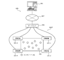
- FIG. 1 is an explanatory diagram showing an operation example of the system according to the present invention.
- FIG. 2 is an explanatory diagram showing an example of a system according to the present invention.
- FIG. 3 is a block diagram illustrating a hardware configuration example of the sensor node 102.
- FIG. 4 is an explanatory diagram showing a premise operation example of the sensor node 102.
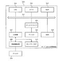
- FIG. 5 is a block diagram illustrating a hardware configuration example of the server 201 and the collection apparatus 101.
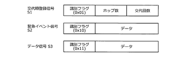
- FIG. 6 is an explanatory diagram illustrating a packet configuration example of each signal.
- FIG. 7 is an explanatory diagram showing power states of components in each operation.
- FIG. 8 is an explanatory diagram illustrating a functional configuration example of the sensor node 102.
- FIG. 1 is an explanatory diagram showing an operation example of the system according to the present invention.
- FIG. 2 is an explanatory diagram showing an example of a system according to the present invention.
- FIG. 3 is a block diagram illustrating
- FIG. 9 is an explanatory diagram illustrating a functional configuration example of the server 201.
- FIG. 10 is an explanatory diagram illustrating a functional configuration example of the collection apparatus 101.
- FIG. 11 is an explanatory diagram illustrating a replacement example.
- FIG. 12 is an explanatory diagram illustrating an example of determining the number of substitutions.
- FIG. 13 is a sequence diagram illustrating an example of transfer of the replacement order registration signal.
- FIG. 14 is an explanatory diagram illustrating an example of the number of hops and the registered order.
- FIG. 15 is an explanatory diagram showing the regular measurement and the lookout time.
- FIG. 16 is an explanatory diagram illustrating a transition example of a look-out node after regular measurement.
- FIG. 16 is an explanatory diagram illustrating a transition example of a look-out node after regular measurement.
- FIG. 17 is a flowchart illustrating an example of a processing procedure at the time of signal reception performed by the sensor node 102.
- FIG. 18 is a flowchart illustrating an example of a processing procedure at the time of timer interruption performed by the sensor node 102.
- FIG. 19 is a flowchart illustrating an example of a processing procedure performed by the sensor node 102 when an emergency event occurs.
- FIG. 20 is a flowchart illustrating an example of a processing procedure performed by the server 201.
- FIG. 21 is a flowchart illustrating an example of a processing procedure performed by the collection apparatus 101.
- FIG. 1 is an explanatory diagram showing an operation example of the system according to the present invention.
- the system 100 is a sensor network system in which a sensor node 102 having a small wireless communication circuit with a sensor forms a sensor network and collects sensor data.
- the system 100 includes a plurality of sensor nodes 102 and a collection device 101.
- the sensor node 102 is a wireless communication node having a sensor, and is provided in the arrangement area 103. For example, the sensor node 102 charges a battery with electric power obtained by self-power generation.
- the collection device 101 is a communication device for collecting sensor data from a plurality of sensor nodes 102. A detailed example of the system 100 is shown in FIG.
- the plurality of sensor nodes 102 alternately switch between the first state St1 and the second state St2 at the same time.
- the first state St1 is a state in which an abnormality notification signal for notifying that an abnormality has occurred is transmitted to the collection apparatus 101 when a predetermined abnormality has occurred in the self sensor node 102.
- the predetermined abnormality is an abnormality having a high degree of urgency, such as a sudden change in the environment of the arrangement area 103, for example.
- the abnormality notification signal is referred to as an emergency event signal, for example.
- the second state St2 is a state in which the data collection device 101 transmits a data signal different from the emergency event signal.
- the notification destination of the emergency event signal and the notification destination of the data signal are the same collection device 101, but different devices may be used.
- the second state St2 is an activated state in which power is supplied to each part of the sensor node 102.
- the second state St2 is a state in which the sensor node 102 performs measurement using a sensor included in the sensor node 102 and transmits a data signal that notifies the measurement value to the communication device.
- the sensor node 102 transfers the data signal transmitted from the other sensor node 102.
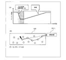
- the process in the second state St2 is referred to as periodic measurement. Since each sensor node 102 performs an intermittent operation as shown in FIG. 4, the battery power is greatly consumed by measurement and data transmission in the second state St2. Therefore, in the present embodiment, the battery of the sensor node 102 is charged during the period I in the first state St1.
- the sensor node 102 enters the third state St3 during a part of the period i included in the period I of the first state St1.
- the third state St3 is a state in which an emergency event signal transmitted from a sensor node 102 other than its own sensor node 102 among a plurality of sensor nodes 102 is received and the received emergency event signal is transferred.
- the sensor node 102 enters the fourth state St4 in which an emergency event signal is not received in a period different from a part of the period i included in the period I of the first state St1.
- the third state St3 is a lookout state described later, and the fourth state St4 is a sleep state described later.
- the third state St3 is a state where power is supplied to the receiving unit included in the sensor node 102
- the fourth state St4 is a state where power is not supplied to the receiving unit included in the sensor node 102.
- the sensor node 102 receives the emergency event signal
- the fourth state St4 the sensor node 102 does not receive the emergency event signal.
- Each sensor node 102 transmits a data signal with the first transmission power.
- Each sensor node 102 transmits an emergency event signal with a second transmission power larger than the first transmission power. Accordingly, even if the number of active sensor nodes 102 is small, an emergency event signal can be transmitted further away, so that the emergency event signal can reach the collection device 101 with a smaller number of times.
- the first ratio between the length of a part of the period i and the length of a part of the period i different from the part of the period i is the arrival distance of the emergency event signal by the second transmission power and the arrival distance of the data signal by the first transmission power. It is a value according to the second ratio.
- the second ratio is the number of substitutions n described later. In the example of FIG. 1, if the arrival distance of the emergency event signal is twice the arrival distance of the data signal, the second ratio is 2. Therefore, the first ratio is 1 / second ratio, and the length of a part of the period i is set to the length of the period I of the first state St1 / second ratio. Thereby, since each sensor node 102 will be in 3rd state St3 only for a shorter period, power consumption can be reduced.
- the sensor node 102 determines the start time of a part of the period i based on the number of hops until the signal transmitted from the collection apparatus 101 reaches the sensor node 102 and the first ratio.
- the sensor node 102-1 enters the third state St3 after the second state St2. Then, the sensor node 102-1 enters the fourth state St4 after the third state St3. Next, the sensor node 102-1 again enters the second state St2 after the fourth state St4. Thus, the sensor node 102-1 is switched in the order of the second state St2, the third state St3, and the fourth state St4.
- the sensor node 102-3, the sensor node 102-5, the sensor node 102-8, and the sensor node 102-10 are in the same state transition as the sensor node 102-1.
- the sensor node 102-2 becomes the fourth state St4 after the second state St2. Then, the sensor node 102-2 enters the third state St3 after the fourth state St4. Next, the sensor node 102-2 again enters the second state St2 after the third state St3. Thus, the sensor node 102-2 is switched in the order of the second state St2, the fourth state St4, and the third state St3.
- the sensor node 102-4, the sensor node 102-6, the sensor node 102-7, and the sensor node 102-9 are in the same state transition as the sensor node 102-2.
- FIG. 2 is an explanatory diagram showing a system example according to the present invention.
- a change in the environment of the arrangement area 103 in which the sensor node 102 is provided is detected by collecting measurement values measured by a plurality of wireless sensor nodes 102, for example.
- the system 100 includes a server 201, a gateway 202, a collection device 101, and a plurality of sensor nodes 102.
- the server 201 and the gateway 202 are connected via a network NET such as the Internet.
- NET such as the Internet.
- each device may be connected to a user terminal via a network NET.
- the server 201 collects, accumulates and analyzes measurement values and controls the entire system 100 such as the gateway 202, the collection device 101, and the sensor node 102.
- the gateway 202 relays the exchange of signals between the network NET to which the server 201 and the user terminal are connected, and the sensor network SNET by the plurality of sensor nodes 102 and the collection device 101.
- the collection apparatus 101 collects measurement values by communicating with the sensor node 102 and notifies the server 201 of the collection results. Further, the collection apparatus 101 may issue an instruction to the sensor node 102, for example.
- the plurality of sensor nodes 102 are communication nodes that measure the state of each position in the arrangement area 103. In addition, the plurality of sensor nodes 102 can communicate with surrounding sensor nodes 102 and the collection device 101 wirelessly.
- FIG. 3 is a block diagram illustrating a hardware configuration example of the sensor node 102.
- the sensor node 102 includes a sensor 301, an MCU (Micro Control Unit) 302, a timer 303, a ROM (Read Only Memory) 304, a RAM (Random Access Memory) 305, and a nonvolatile memory 306.
- the sensor node 102 includes a wireless circuit 308, an antenna 309, a power management unit 310, a battery 311, a harvester 312, and the like.
- the sensor node 102 includes an internal bus 307 that connects the sensor 301, the MCU 302, the timer 303, the ROM 304, the RAM 305, and the nonvolatile memory 306.
- a dotted arrow indicates a power supply line
- a solid arrow indicates a signal line.
- Sensor 301 detects a predetermined amount of displacement at the installation location.
- the sensor 301 for example, a piezoelectric element that detects a pressure at an installation location, an element that detects temperature, a photoelectric element that detects light, or the like can be used.
- a plurality of types of sensors 301 may be provided.
- the measurement timing may be divided like the sensor 301-1 for regular measurement and the sensor 301-2 for emergency event. In the regular measurement, each sensor node 102 performs measurement by the sensor 301-1 at every first predetermined interval, and notifies the collection device 101 of the measurement value.
- each sensor node 102 performs measurement by the sensor 301-2 at a second predetermined interval shorter than the first predetermined interval, and determines whether there is an abnormality based on the measurement value. In the measurement for an emergency event, when each sensor node 102 determines that there is an abnormality, the sensor node 102 notifies the collection device 101 that an abnormality has occurred urgently.
- the MCU 302 is a control unit that performs overall control and data processing of the sensor node 102 by, for example, loading a program stored in the ROM 304 into the RAM 305 and executing the program.
- the MCU 302 processes data detected by the sensor 301.
- the timer 303 counts the time set by the MCU 302 or the like. In the present embodiment, for example, the timer 303 counts the sensing interval for sensing by the sensor 301 spontaneously. In addition, for example, the timer 303 counts a predetermined period during which the short-range wireless circuit is stopped in the second embodiment described later.
- the ROM 304 is a storage unit that stores programs executed by the MCU 302.
- the RAM 305 is a storage unit that stores temporary data for processing in the MCU 302.
- the non-volatile memory 306 is a writable memory, and is a storage unit that holds predetermined data that is written even when power supply is interrupted.
- the writable nonvolatile memory 306 includes a flash memory.
- the storage unit such as the ROM 304 and the non-volatile memory 306 stores, for example, the turn order.
- the antenna 309 transmits and receives radio waves for wireless communication with other sensor nodes 102 and the gateway 202.
- the radio circuit 308 is RF (Radio Frequency).
- the wireless circuit 308 includes a reception circuit 322 that outputs a radio wave received via the antenna 309 as a reception signal, and a transmission circuit 321 that transmits a transmission signal via the antenna 309 as a radio wave.
- the transmission power of the transmission circuit 321 can be switched by the MCU 302.
- the transmission circuit 321 can be switched to at least two transmission powers of the first transmission power and the second transmission power.
- the first transmission power is power that allows a transmission signal to directly communicate with the sensor node 102 disposed at a short distance.
- the second transmission power is a transmission power stronger than the first transmission power, and is a power with which a transmission signal can be directly communicated to the collection apparatus 101.
- the first transmission power and the second transmission power are determined based on the arrangement area 103 of the sensor node 102, the number of arrangement of the sensor nodes 102, the arrangement position of the collection device 101, and the like.
- each transmission power of the transmission circuit 321 is set so that a signal can reach a predetermined distance.
- the reachable distance of the radio wave by the first transmission power is also called a first radio wave arrival distance
- the distance by which the radio wave by the second transmission power of the transmission circuit 321 reaches is also called a second radio wave arrival distance.
- the harvester 312 generates power based on the external environment at the location where the sensor node 102 is installed, for example, energy changes such as light, vibration, temperature, and radio waves. In the example of FIG. 3, only one harvester 312 is provided. However, the invention is not limited to this, and the same type of harvester 312 may be provided, or a plurality of different types of harvesters 312 may be provided. Good.
- the harvester 312 may generate power according to the amount of displacement detected by the sensor 301, or may generate power according to the amount of displacement of the received radio wave received by the wireless circuit 308.
- the battery 311 stores the electric power generated by the harvester 312.
- the sensor node 102 is not provided with a primary battery, an external power source, or the like, and generates electric power required for operation inside the own device.
- the power management unit 310 performs control to supply the power stored by the battery 311 to each unit of the sensor node 102 as a driving power source.
- FIG. 4 is an explanatory diagram showing an example of a premise operation of the sensor node 102.
- each sensor node 102 performs an intermittent operation. In the intermittent operation, each sensor node 102 is activated from the sleep state every predetermined time. The predetermined time is determined by the user. And each sensor node 102 measures the state of an arrangement
- the state of being activated is referred to as an activated state. Further, the activated state here is the second state St2 shown in FIG. Further, as shown in FIG.
- the remaining amount of the battery 311 is reduced in the activated state by processing by the MCU 302, wireless transmission by the transmission circuit 321, reception by the reception circuit 322, and the like.
- the remaining amount of the battery 311 increases due to charging in the sleep state.
- the plurality of sensor nodes 102 use multi-hop communication for data signals for notifying the collection device 101 of measured values of the sensors 301 included in each sensor node 102. Relay transfer. Further, as described above, each sensor node 102 sets the transmission power of the transmission circuit 321 as the first transmission power in the activated state.
- FIG. 5 is a block diagram illustrating a hardware configuration example of the server 201 and the collection apparatus 101. Since the server 201 and the collection device 101 may have the same configuration, the server 201 and the collection device 101 will be described as the same configuration. In order to indicate either the server 201 or the collection device 101, in FIG.
- the device 500 operates based on an external power source.
- the apparatus 500 includes a CPU (Central Processing Unit) 501, a timer 502, a ROM 503, a RAM 504, a disk drive 505, a disk 506, and an I / O (Input / Output) circuit 507.
- the apparatus 500 includes an internal bus 511 that connects a CPU 501, a timer 502, a ROM 503, a RAM 504, a disk drive 505, and an I / O circuit 507.
- the CPU 501 is a control unit that controls the entire apparatus 500.
- the ROM 503 is a storage unit that stores programs such as a boot program.
- the RAM 504 is a storage unit used as a work area for the CPU 501.
- the disk drive 505 controls reading / writing of data with respect to the disk 506 according to the control of the CPU 501.
- the disk 506 is a storage unit that stores data written under the control of the disk drive 505. Examples of the disk 506 include a magnetic disk and an optical disk.
- the storage unit such as the ROM 503 and the disk 506 stores the collection device list 910 including the identification information of the collection device 101 and the arrangement position of the collection device 101 shown in FIG.
- the storage unit such as the ROM 503 or the disk 506 stores the first radio wave arrival distance r of the radio wave by the first transmission power of the transmission circuit 321 and the radio wave by the second transmission power of the transmission circuit 321.
- the second radio wave arrival distance R is stored.
- a wireless communication circuit 508 and an antenna 509 are connected to the I / O circuit 507.
- wireless communication can be performed with the collection device 101 by performing wireless communication with the gateway 202 via the wireless communication circuit 508 and the antenna 509.
- wireless communication can be performed with the sensor node 102 via the wireless communication circuit 508 and the antenna 509.
- a network I / F 510 is connected to the I / O circuit 507.
- the device 500 can communicate with an external device via a network such as the Internet through a network I / F 510 by TCP (Transmission Control Protocol) / IP (Internet Protocol) protocol processing.
- TCP Transmission Control Protocol
- IP Internet Protocol
- wired communication or wireless communication can be applied to communication via the network I / F 510.
- the device 500 may be provided with an input device such as a keyboard, a mouse, or a touch panel. As a result, the user can directly operate the device 500 via the input device. Further, for example, an output device such as a display, a printer, or a buzzer may be provided in the device 500. Thereby, for example, when an abnormality occurs, the device 500 may output an abnormality to the output device according to the type of abnormality.
- an input device such as a keyboard, a mouse, or a touch panel.
- an output device such as a display, a printer, or a buzzer may be provided in the device 500.
- the device 500 may output an abnormality to the output device according to the type of abnormality.
- FIG. 6 is an explanatory diagram showing a packet configuration example of each signal.
- the alternation order registration signal S1 is a signal for registering the order in which each sensor node 102 supplies power to the receiving circuit 322 in the sleep state.
- the replacement order registration signal S1 is relay-transferred from the collection device 101 to each sensor node 102 by multi-hop communication between the sensor nodes 102.
- the replacement order registration signal S1 includes an identification flag, the number of hops, and the number of replacements.
- the identification flag is information indicating that the signal is the alternation order registration signal S1, and is a predetermined value so as not to overlap with the identification flag of other signals, for example, a fixed value such as 0x01.
- the number of hops is the number of other sensor nodes 102 that have passed between the collection apparatus 101 and the sensor node 102.
- the number of replacements is a number indicating how many times the sensor nodes 102 are switched in the measurement interval.
- the emergency event signal S2 is a signal for notifying the collecting apparatus 101 that an emergency abnormality has occurred.
- the emergency event signal S2 has an identification flag and data.
- the identification flag is information indicating that it is the emergency event signal S2, and is a predetermined value so as not to overlap with the identification flag of other signals, for example, a fixed value such as 0x10.
- the data includes, for example, identification information of the sensor node 102 in which an abnormality has occurred, the type of emergency event, a measurement value, and the like.
- the type of emergency event may be the type of sensor 301. In the example described above, there is one type of emergency event sensor 301-2, but a plurality of types may be provided, so the type of sensor 301 is included in the emergency event signal S2.
- the data signal S3 is a signal for notifying the collection device 101 of the measurement value.
- the data signal S3 has an identification flag and data.
- the identification flag is information indicating that it is the data signal S3, and is a predetermined value so as not to overlap with the identification flag of other signals, and is a fixed value such as 0x11, for example.
- Examples of the data include a measured value and identification information of the measured sensor node 102.
- FIG. 6 shows an example of the configuration of each signal, but the present invention is not limited to this, and various changes can be made.
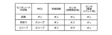
- FIG. 7 is an explanatory diagram showing power states of components in each operation.
- the sensor node 102 has an activated state, a lookout state, and a sleep state.
- the activation state is the second state St2 shown in FIG. 1
- the look-out state is the third state St3 shown in FIG. 1
- the sleep state is the fourth state St4 shown in FIG. is there.
- the power state of the MCU 302 includes an on state and a sleep state.
- the ON state is a state in which voltages that can be processed by the MCU 302 are supplied to the MCU 302.
- the sleep state is a state in which power is supplied to an interrupt circuit and the like included in the MCU 302 and the timer 303, and power is not supplied to a circuit having a main function such as computation of the MCU 302.
- the interrupt circuit included in the MCU 302 receives an interrupt signal, the MCU 302 is turned on. Further, the MCU 302 has an off state in which power is not supplied to all and all operations are not possible, but the off state is not used in this embodiment.
- the power state of the receiving circuit 322 has an on state and an off state.
- the on state is a state in which power is supplied to the receiving circuit 322.
- the off state is a state in which power is not supplied to the receiving circuit 322 and a state in which radio waves cannot be received.
- the power state of the sensor 301 includes an on state and an off state.
- the on state is a state in which power is supplied to the sensor 301.
- the off state is a state where power is not supplied to the sensor 301.
- the MCU 302 is in the on state
- the receiving circuit 322 is in the on state
- the periodic measurement sensor 301-1 is in the on state
- the emergency event sensor 301 -2 is the ON state.
- the MCU 302 when the state of the sensor node 102 is the lookout state, the MCU 302 is in the sleep state, the receiving circuit 322 is in the on state, the periodic measurement sensor 301-1 is in the off state, and the emergency event sensor 301 -2 is the ON state.
- the MCU 302 when the sensor node 102 is in the sleep state, the MCU 302 is in the sleep state, the reception circuit 322 is in the off state, the periodic measurement sensor 301-1 is in the off state, and the emergency event sensor 301. -2 is the ON state.
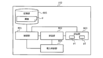
- FIG. 8 is an explanatory diagram illustrating a functional configuration example of the sensor node 102.
- the sensor node 102 includes a control unit 801, a reception unit 802, a transmission unit 803, a power control unit 804, and a storage unit 805.
- the receiving unit 802 is realized by the receiving circuit 322.
- the transmission unit 803 is realized by the transmission circuit 321.
- the power control unit 804 is realized by the power management unit 310.
- the storage unit 805 is realized by, for example, the ROM 304, the RAM 305, the nonvolatile memory 306, and the like.
- the control unit 801 is realized by, for example, the MCU 302 or the timer 303.
- Each process of the control unit 801 is coded in a program stored in the storage unit 805 accessible by the MCU 302, for example. Then, the MCU 302 reads out the program from the storage unit 805 and executes the process coded in the program. Thereby, each process of the control part 801 is implement
- FIG. 9 is an explanatory diagram illustrating a functional configuration example of the server 201.
- the server 201 includes a control unit 901, a reception unit 902, a transmission unit 903, and a storage unit 904.
- the reception unit 902 and the transmission unit 903 are realized by the wireless communication circuit 508, for example.
- the control unit 901 is realized by the CPU 501 and the like.
- Each process of the control unit 901 is coded in a program stored in the storage unit 904 accessible by the CPU 501, for example.
- the CPU 501 reads the program from the storage unit 904 and executes the process coded in the program. Thereby, each process of the control part 901 is implement
- the processing result of each unit is stored in the storage unit 904, for example.
- FIG. 10 is an explanatory diagram illustrating a functional configuration example of the collection apparatus 101.
- the collection apparatus 101 includes a control unit 1001, a reception unit 1002, a transmission unit 1003, and a storage unit 1004.
- the receiving unit 1002 and the transmitting unit 1003 are realized by the wireless communication circuit 508, for example.
- the control unit 1001 is realized by the CPU 501 or the like.
- Each process of the control unit 1001 is coded in a program stored in the storage unit 1004 accessible by the CPU 501, for example.
- the CPU 501 reads the program from the storage unit 1004 and executes the process coded in the program. Thereby, each process of the control unit 1001 is realized.
- the processing result of each unit is stored in the storage unit 1004, for example.
- FIG. 11 is an explanatory diagram showing a replacement example.
- the sensor node 102 in the watch state is also called a watch node
- the sensor node 102 in the sleep state is also called a sleep node.
- the look-out nodes are the sensor nodes 102-1 to 102-5. Since the watch node is supplied with power to the receiving circuit 322, the power consumption of the battery 311 is larger than that of the sleep node. Therefore, if the same sensor node 102 is always a lookout node, there is a possibility that the power of the battery 311 is insufficient, so that the lookout state and the sleep state are switched.
- the look-out nodes are sensor nodes 102-6 to 102-10, and the sensor nodes 102-1 to 102-5 are sleep nodes.
- the server 201 determines, for example, the number of times to switch between the watch state and the sleep state at the start of operation. Then, the server 201 determines the order of switching to each of the plurality of sensor nodes 102 based on the determined number of substitutions.
- FIG. 12 is an explanatory diagram showing an example of determining the number of times of replacement.
- the control unit 901 determines the number of alternations for switching between the watch state and the sleep state. For example, as illustrated in FIG. 12A, the control unit 901 determines the number of substitutions n based on the ratio of the first radio wave arrival distance r and the second radio wave arrival distance R. In the example of FIG. 12, the number of substitutions n is the maximum real number not exceeding R / r ([] in FIG. 12 is a Gaussian symbol).
- the control unit 901 stores the determined number of substitutions n in the storage unit 904.
- any one of the sensor nodes 102-8 to 102-11 may be a lookout node.
- the sensor node 102-4 to the sensor node 102-7 can receive the signal. Therefore, any one of the sensor nodes 102-4 to 102-7 may be a lookout node.
- the control unit 901 selects one of the collection devices 101 from the collection devices 101 based on the collection device list 910. Then, the transmission unit 903 transmits an instruction to transmit a replacement order registration signal including the number of replacements n to the plurality of sensor nodes 102 to the collection apparatus 101 selected by the control unit 901.
- the collection device list 910 includes, for example, identification information of the collection device 101, an arrangement position of the collection device 101, and the like.
- the reception unit 1002 receives an instruction from the transmission unit 903. Based on the instruction received by the receiving unit 1002, the control unit 1001 generates a replacement order registration signal S1 with the number of hops set to 0 and the number of replacements set to n. Then, the transmission unit 1003 transmits the generated replacement order registration signal S1 to the plurality of sensor nodes 102.
- the receiving unit 802 receives the replacement order registration signal S1. Then, the control unit 801 calculates a remainder when the number of hops included in the replacement order registration signal S1 is divided by the number of replacements n included in the replacement order registration signal S1. The control unit 801 stores the calculated remainder in the storage unit 805 as the order d. Then, the control unit 801 generates a replacement order registration signal S1 in which the number of hops is counted up by one. Next, the transmission unit 803 transmits the generated replacement order registration signal S1.
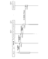
- FIG. 13 is a sequence diagram showing a transfer example of the change order registration signal.
- the server 201 transmits, to the collection apparatus 101, an instruction that causes the collection apparatus 101 to perform the change order registration on the plurality of sensor nodes 102 (step S1301).
- the collection apparatus 101 transmits the replacement order registration signal S1 to the plurality of sensor nodes 102 (step S1302).
- the sensor node 102-0 receives the replacement order registration signal S1
- the sensor node 102-0 registers the order d based on the received replacement order registration signal S1.
- the sensor node 102-0 transfers the replacement order registration signal S1 in which the hop count is incremented by 1 (step S1303).
- the sensor node 102-1 when receiving the replacement order registration signal S1, the sensor node 102-1 registers the order d based on the received replacement order registration signal S1. Then, for example, the sensor node 102-1 transfers the replacement order registration signal S1 with the hop count incremented by 1 (step S1304). In this way, the change order registration signal S1 is transmitted to the sensor node 102-N by relay transfer.
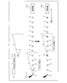
- FIG. 14 is an explanatory diagram showing an example of the number of hops and the registered order.
- the number n of substitutions is 4 will be described as an example.
- the order d is 0.
- the number of hops included in the replacement order registration signal S1 is 1, so the order d is 1.
- the order d is 2.
- the number of hops included in the replacement order registration signal S1 is 3, so the order d is 3.
- the order d is 0 because the number of hops included in the replacement order registration signal S1 is four.
- the order d is 0 for the sensor node 102-4 and the sensor node 102-8. In the example of FIG. 14, the order d is 1 for the sensor node 102-5 and the sensor node 102-9. In the example of FIG. 14, the order d is 2 for the sensor node 102-6 and the sensor node 102-10. In the example of FIG. 14, the order d is 3 for the sensor node 102-7 and the sensor node 102-11.
- the control unit 801 enters an activated state at every measurement interval counted by the timer 502 and performs periodic measurement by the sensor 301-1.
- the control unit 801 generates a data signal S3 that notifies the collection device 101 of the measurement value measured by the sensor 301-1.
- the control unit 801 sets the transmission power of the transmission unit 803 to the first transmission power p1. Then, the transmission unit 803 transmits the generated data signal S3 with the first transmission power p1.
- the reception unit 802 notifies the collection device 101 of the measurement values measured by the sensor nodes 102 other than the own sensor node 102 from the sensor nodes 102 other than the own sensor node 102 among the plurality of sensor nodes 102.
- the control unit 801 sets the transmission power of the transmission unit 803 to the second transmission power p2.
- the transmission unit 803 transfers the received data signal S3 with the second transmission power p2.
- each data signal is relay-transferred to the collection device 101 by multi-hop communication between the sensor nodes 102.
- the control unit 801 sets the measurement interval and the watch time in the timer 502. Then, the control unit 801 instructs the power control unit 804 to shift the state of the sensor node 102 from the activated state to the sleep state.
- the power control unit 804 controls the power supply voltage supplied to the MCU 302 to be lowered in order to shift the sensor node 102 to the sleep state.
- the power control unit 804 performs control so that power is not supplied to the reception circuit 322 and the periodic measurement sensor 301-1. However, the power is still supplied to the emergency event sensor 301-2.
- the control unit 801 may set the transmission power of the transmission unit 803 to the second transmission power p2.
- the transmission unit 803 can transmit the emergency event signal S2 with the second transmission power p2 that is the maximum transmission power.
- the power control unit 804 supplies power to the reception circuit 322 in order to shift the state of the sensor node 102 from the sleep state to the watch state when the watch 303 starts counting by the timer 303.
- the transmitting unit 803 transmits the received emergency event signal S2 with the second transmission power p2.
- the power control unit 804 controls not to supply power to the reception circuit 322 in order to shift the state of the sensor node 102 from the watch state to the sleep state when the watch end time is reached by counting by the timer 303.
- the watch start time when the sensor node 102 becomes the watch node is determined by the following formula (1)
- the watch end time when the sensor node 102 becomes the sleep node from the watch node is determined by the following formula (2).
- the time is determined by the following equation (3).
- Lookout start time TS i x d seconds after regular measurement (1)
- Lookout end time TE i ⁇ (d + 1) seconds after regular measurement (2)
- Measurement interval I
- the measurement interval I is the same as the period I of the first state St1 shown in FIG. 1, and the watch time i is the same as a part of the period i shown in FIG.
- FIG. 15 is an explanatory diagram showing the regular measurement and the lookout time. After each sensor node 102 performs regular measurement at the same time, the timer 303 counts the measurement interval I, and the timer 303 counts the watch start time and the watch end time.
- the sensor node 102-0 and the sensor node 102-4 whose order d is 0 change from the activated state to the lookout state at the lookout start time TS0, and enter the sleep state at the lookout end time TE0.
- the sensor nodes 102-1 to 102-3 and the sensor node 102-N whose order d is 1 to 3 are in the sleep state.
- the sensor node 102-1 in which the order d is 1 goes from the sleep state to the watch state at the watch start time TS1, and goes from the watch state to the sleep state at the watch end time TE1.
- the sensor node 102-0, the sensor node 102-2 to the sensor node 102-4, and the sensor node 102- whose order d is any one of 0, 2, and 3 N is a sleep state.
- the sensor node 102-2 in which the order d is 2 goes from the sleep state to the watch state at the watch start time TS2, and goes from the watch state to the sleep state at the watch end time TE2. Further, in the period from the watch start time TS2 to the watch end time TE2, the sensor node 102-0, the sensor node 102-1, the sensor node 102-3, and the sensor node 102- whose order d is any one of 0, 1, and 3 4 and the sensor node 102-N are in a sleep state.
- the sensor node 102-3 and the sensor node 102-N in which the order d is 3 change from the sleep state to the look-out state at the look-off start time TS3, and change from the look-out state to the start-up state at the look-out end time TE3.
- the reason why the watch enters the activated state is that the counting of the measurement interval I by the timer 303 ends.
- the sensor node 102-0 to the sensor node 102-2 and the sensor node 102-4 whose order d is either 0, 1, or 2 during the period from the watch start time TS3 to the watch end time TE3 are in the sleep state. is there.
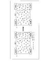
- FIG. 16 is an explanatory diagram showing a transition example of a look-out node after regular measurement.
- the example of FIG. 16 is an example in which the number n of substitutions is 4, and the substitution order registration signal S1 is transmitted from the collection apparatus 101-3.
- FIG. 16 (1) shows a lookout node in a period from 0 seconds to i seconds after the regular measurement is performed.
- (2) in FIG. 16 shows a look-out node in a period from i seconds to 2 i seconds after the regular measurement is performed.
- (3) in FIG. 16 shows a lookout node in a period from 2i seconds to 3i seconds after regular measurement is performed.
- (4) in FIG. 16 shows a lookout node in a period from 3i seconds to 4i seconds after periodic measurement is performed.
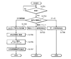
- FIG. 17 is a flowchart illustrating an example of a processing procedure at the time of signal reception performed by the sensor node 102.
- the sensor node 102 determines whether or not a signal has been received (step S1701). If it is determined that no signal has been received (step S1701: NO), the sensor node 102 returns to step S1701.
- step S1701 If it is determined that the signal has been received (step S1701: Yes), the sensor node 102 determines the type of the received signal (step S1702). When it is determined that the received signal is an emergency event signal (step S1702: emergency event), the sensor node 102 transfers the emergency event signal S2 with the second transmission power p2 (step S1703), and performs a series of processes. finish.
- step S1702 data
- the sensor node 102 transfers the data signal S3 with the first transmission power p1 (step S1708), and ends a series of processes.
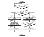
- FIG. 18 is a flowchart showing an example of a processing procedure at the time of timer interruption performed by the sensor node 102.
- the sensor node 102 determines whether a timer interrupt has been accepted (step S1801). If the timer interrupt has not been received (step S1801: NO), the sensor node 102 returns to step S1801.
- the sensor node 102 determines the type of interrupt (step S1802).
- the sensor node 102 is activated by supplying power to the MCU 302, and performs periodic measurement. This is performed (step S1803).
- the regular measurement measurement by the sensor 301, transmission of a data signal including a measurement value by the first transmission power p1, synchronization processing with other sensor nodes 102, and the like are performed.
- the synchronization processing indicates transition to a sleep state or a watch state after a predetermined time has elapsed from the start of measurement.
- each sensor node 102 Since each sensor node 102 counts the measurement interval, an error occurs in the transmission of the data signal. Therefore, a predetermined time elapses from the measurement start time when it is estimated that the transmission of the data signal by each sensor node 102 ends. Therefore, more data signals can reach the collection device 101 by performing the synchronization process.
- the sensor node 102 sets the timer 303 so that the timer interrupt occurs after the measurement interval I seconds and the watch time i ⁇ d seconds (step S1804). Then, the sensor node 102 stops supplying power to the receiving circuit 322 and lowers the voltage of the power supply to the MCU 302, thereby shifting to the sleep state (step S1805) and ending a series of processing.
- step S1802 watch time i ⁇ d seconds
- the sensor node 102 supplies power to the receiving circuit 322 to keep the watch.
- the state is shifted (step S1806).
- the sensor node 102 determines whether or not the lookout time i seconds has elapsed (step S1807). If it is determined that the lookout time i seconds has not elapsed (step S1807: NO), the sensor node 102 returns to step S1807.
- step S1807 If it is determined that the watching time i seconds has elapsed (step S1807: YES), the sensor node 102 shifts to the sleep state by not supplying power to the reception circuit 322 (step S1808), and ends the series of processing. .
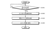
- FIG. 19 is a flowchart illustrating an example of a processing procedure performed by the sensor node 102 when an emergency event occurs.
- the sensor node 102 determines whether or not an interrupt signal from the sensor 301 has been received (step S1901). If it is determined that no interrupt signal has been received (step S1901: NO), the sensor node 102 returns to step S1901.
- step S1901 If it is determined that an interrupt signal has been received (step S1901: YES), the sensor node 102 acquires a measurement value from the sensor 301 (step S1902). The sensor node 102 transmits an emergency event signal having the acquired measurement value and the type of the sensor 301 (step S1903). Then, the sensor node 102 shifts to a sleep state (step S1904) and ends a series of processes.
- FIG. 20 is a flowchart illustrating an example of a processing procedure performed by the server 201.
- the server 201 calculates the number of substitutions n (step S2001).
- the server 201 selects one collection device 101 and instructs the selected collection device 101 to register the replacement order (step S2002).
- the server 201 performs regular measurement (step S2003). In the regular measurement, the state of the arrangement area 103 and the like are observed based on the collected measurement values of each sensor node 102.
- step S2004 determines whether there is an emergency event.
- step S2004 determines whether there is an urgent event.
- step S2005 processes the urgent event (step S2005), and proceeds to step S2006.
- step S2006 determines whether a predetermined time has elapsed (step S2006).
- the predetermined time is the measurement interval I described above.
- the server 201 may count the measurement interval I by the timer 502.
- step S2006: No the server 201 returns to step S2004.
- step S2006: Yes the server 201 returns to step S2003.
- FIG. 21 is a flowchart illustrating an example of a processing procedure performed by the collection apparatus 101.
- the collection apparatus 101 determines whether a signal has been received (step S2101). If it is determined that the information has not been received (step S2101: No), the collection apparatus 101 returns to step S2101. On the other hand, when it is determined that an emergency event signal has been received (step S2101: emergency event), the collection apparatus 101 notifies the server 201 of the emergency event (step S2102), and ends a series of processing.
- step S2101 replacement order registration
- the collection apparatus 101 transmits a replacement order registration signal with the number of hops being 0 and the number of replacements being n. (Step S2103), a series of processing ends.
- the reception circuit of the sensor node 102 is activated during the suspension period.
- the operation state and the hibernation state of the receiving circuit are switched for each sensor node 102, and an abnormality is caused by some sensor nodes 102 in the operation state.
- the notification signal is transferred. Thereby, it becomes possible to perform abnormality notification during the charging period while suppressing power consumption.
- the operating state is the above-described watch state.
- Each sensor node 102 transmits a data signal with the first transmission power.
- Each sensor node 102 transmits an abnormality notification signal with a second transmission power p2 that is greater than the first transmission power.
- the abnormality notification signal can be transmitted further, so that the abnormality notification signal can reach the collection device 101 with a smaller number of times.
- the length of the operating state of the receiving circuit and the length of the resting state of the receiving circuit are the first of the arrival distance of the emergency event signal by the second transmission power p2 and the arrival distance of the data signal by the first transmission power. 2 Value according to the ratio.
- the sensor node 102 determines the start time of a part of the period based on the number of hops until the signal transmitted from the collection device 101 reaches the sensor node 102 before operation. As a result, the accuracy with which the abnormality notification signal reaches the collection device 101 is improved.
- the switching method described in this embodiment can be realized by executing a program prepared in advance by the MCU 302.
- This program is recorded on a recording medium readable by the MCU 302 such as the ROM 304 and the nonvolatile memory 306, and is executed by being read from the recording medium by the MCU 302.
- this program may be distributed by the server via the collection device.
Landscapes
- Engineering & Computer Science (AREA)
- Computer Networks & Wireless Communication (AREA)
- Signal Processing (AREA)
- Mobile Radio Communication Systems (AREA)
- Arrangements For Transmission Of Measured Signals (AREA)
Abstract
複数のセンサノード(102)は、同時期に各々が、自センサノード(102)において所定の異常が発生した場合に異常が発生したことを通知する異常通知信号を収集装置(101)へ送信する第1状態(St1)と、異常通知信号と異なるデータ信号を通信装置へ送信する第2状態(St2)と、を交互に切り替える。センサノード(102)は、第1状態(St1)の期間(I)の各々では、第1状態(St1)の期間(I)に含まれる一部の期間(i)に複数のセンサノード(102)のうち自センサノード(102)以外のセンサノード(102)から送信される異常通知信号を受信し、受信した異常通知信号を転送する第3状態(St3)となる。センサノード(102)は、第1状態(St1)の期間(I)の各々では、第1状態(St1)の期間(I)に含まれる一部の期間(i)と異なる期間に異常通知信号を受信しない第4状態(St4)となる。
Description
本発明は、システム、通信ノード、および切り替え方法に関する。
従来、センサネットワークシステムでは、多数の無線のセンサノードによってセンサノードが設けられた領域の環境の変化などを検出することが公知である。また、従来、センサノード間のマルチホップ通信によるリレー転送によって直接接続されていないセンサノードにデータを送信する技術が公知である。
また、従来、リレー転送を行う場合に、定期的に周辺のセンサノードと中継処理を行っているか否かの情報を交換し、周辺に中継処理を行うノードがない場合に常時受信機能動作状態とし、中継端末がある場合に定期受信期間以外スリープ状態とする技術が公知である(例えば、以下特許文献1参照。)。これにより、一部のセンサノードによって集計処理が行われるようになる。
また、従来、消費電力量を低減させるために、隣接ノードのスリープ情報や残留エネルギー情報に基づいて、スリープ状態となる期間を決定する技術が公知である(例えば、以下特許文献2参照。)。
また、従来、マルチホップ通信によってデータを転送するセンサネットワークにおいて、基地局から距離に応じて端末をグループ分けし、一定周期で通信するとき以外はスリープ状態にし、緊急情報を検知した端末は情報発信の周期を短くする技術が公知である(例えば、以下特許文献3参照。)。
しかしながら、例えばセンサノードが間欠動作を行う場合に、センサノードによって検出された異常を休止期間中にも通知するためには休止期間中にセンサノードの受信回路を起動することになり、消費電力が多くなるという問題がある。
1つの側面では、本発明は、消費電力の低減を図ることができるシステム、通信ノード、および切り替え方法を提供することを目的とする。
本発明の一側面によれば、自通信ノードにおいて所定の異常が発生した場合に前記異常が発生したことを通知する異常通知信号を通信装置へ送信する第1状態と、前記異常通知信号と異なるデータ信号を前記通信装置へ送信する第2状態と、を各々が同時期に交互に切り替える複数の通信ノードに含まれ、前記第1状態の期間の各々では、前記第1状態の期間に含まれる一部の期間に前記複数の通信ノードのうち自通信ノード以外の通信ノードから送信される前記異常通知信号を受信し、受信した前記異常通知信号を転送する第3状態となり、前記第1状態の期間に含まれる前記一部の期間と異なる期間に前記異常通知信号を受信しない第4状態となるシステム、通信ノード、および切り替え方法が提案される。
本発明の一態様によれば、消費電力の低減を図ることができる。
以下に添付図面を参照して、本発明にかかるシステム、通信ノード、および切り替え方法の実施の形態を詳細に説明する。
図1は、本発明にかかるシステムの動作例を示す説明図である。システム100は、センサと小型の無線通信回路を有するセンサノード102がセンサネットワークを形成し、センサのデータを収集できるセンサネットワークシステムである。システム100は、複数のセンサノード102と、収集装置101と、を有する。センサノード102は、センサを有する無線の通信ノードであり、配置領域103に設けられる。例えば、センサノード102は、自発電によって得られた電力をバッテリに充電する。収集装置101は、複数のセンサノード102からセンサのデータを収集するための通信装置である。システム100の詳細例については、図2に示す。
複数のセンサノード102は、同時期に各々が、第1状態St1と、第2状態St2と、を交互に切り替える。例えば、第1状態St1は、自センサノード102において所定の異常が発生した場合に異常が発生したことを通知する異常通知信号を収集装置101へ送信する状態である。所定の異常とは、例えば、配置領域103の環境の急激な変化などの緊急度の高いような異常である。ここで、異常通知信号は、例えば、緊急イベント信号と称する。第2状態St2は、緊急イベント信号と異なるデータ信号を収集装置101によって送信する状態である。ここでは、緊急イベント信号の通知先と、データ信号の通知先を同じ収集装置101にしているが、異なる装置あってもよい。
第2状態St2は、センサノード102の各部に電源が供給された起動状態である。具体的に、まず、第2状態St2は、センサノード102が、センサノード102が有するセンサによって測定を行い、測定値を通知するデータ信号を通信装置へ送信する状態である。また、第2状態St2では、センサノード102は、他のセンサノード102から送信されたデータ信号を転送する。ここで、第2状態St2における処理を定期測定と称する。各センサノード102は、図4に示すような間欠動作を行うため、第2状態St2における測定およびデータ送信によりバッテリの電力を大幅に消耗してしまう。そこで、本実施の形態では、第1状態St1の期間Iに自センサノード102が有するバッテリ充電を行う。
センサノード102は、第1状態St1の期間Iの各々では、第1状態St1の期間Iに含まれる一部の期間iに第3状態St3となる。第3状態St3は、複数のセンサノード102のうち自センサノード102以外のセンサノード102から送信される緊急イベント信号を受信し、受信した緊急イベント信号を転送する状態である。また、センサノード102は、第1状態St1の期間Iの各々では、第1状態St1の期間Iに含まれる一部の期間iと異なる期間に緊急イベント信号を受信しない第4状態St4となる。第3状態St3は後述する見張り状態であり、第4状態St4は後述するスリープ状態である。
例えば、第3状態St3は、センサノード102が有する受信部に電源が供給される状態であり、第4状態St4は、センサノード102が有する受信部に電源が供給されない状態である。これにより、第3状態St3では、センサノード102が緊急イベント信号を受信し、第4状態St4ではセンサノード102が緊急イベント信号を受信しないようになる。
また、各センサノード102は、データ信号を第1送信電力によって送信する。各センサノード102は、緊急イベント信号を第1送信電力よりも大きい第2送信電力によって送信する。これにより、稼働しているセンサノード102の数が少なくても、より遠くに緊急イベント信号を送信することができるため、より少ない回数によって緊急イベント信号が収集装置101へ到達可能となる。
また、一部の期間iの長さと一部の期間iと異なる期間の長さとの第1比率は、第2送信電力による緊急イベント信号の到達距離と第1送信電力によるデータ信号の到達距離との第2比率に応じた値である。第2比率は後述する交代回数nである。図1の例では、緊急イベント信号の到達距離がデータ信号の到達距離の2倍であれば、第2比率は2となる。そのため、第1比率は、1/第2比率であり、一部の期間iの長さを第1状態St1の期間Iの長さ/第2比率とする。これにより、各センサノード102がより短い期間だけ第3状態St3となるため、消費電力量を低減させることができる。
また、センサノード102は、運用前に、一部の期間iの開始時刻を、収集装置101から送信された信号がセンサノード102に到達するまでのホップ数と第1比率によって決定する。
例えば、センサノード102-1は、第2状態St2の後に第3状態St3となる。そして、センサノード102-1は、第3状態St3の後に第4状態St4となる。つぎに、センサノード102-1は、第4状態St4の後に再度第2状態St2となる。このように、センサノード102-1は、第2状態St2、第3状態St3、第4状態St4の順に切り替えられる。また、センサノード102-3とセンサノード102-5とセンサノード102-8とセンサノード102-10とはセンサノード102-1と同様の状態遷移である。
例えば、センサノード102-2は、第2状態St2の後に第4状態St4となる。そして、センサノード102-2は、第4状態St4の後に第3状態St3となる。つぎに、センサノード102-2は、第3状態St3の後に再度第2状態St2となる。このように、センサノード102-2は、第2状態St2、第4状態St4、第3状態St3の順に切り替えられる。また、センサノード102-4とセンサノード102-6とセンサノード102-7とセンサノード102-9とはセンサノード102-2と同様の状態遷移である。
図2は、本発明にかかるシステム例を示す説明図である。システム100では、複数の無線のセンサノード102によって測定された測定値を収集するなどによってセンサノード102が設けられた配置領域103の環境の変化などを検出する。
具体的に、システム100は、サーバ201と、ゲートウェイ202と、収集装置101と、複数のセンサノード102と、を有する。サーバ201とゲートウェイ202とは、インターネットなどのネットワークNETを介して接続される。また、図示していないが、各装置がネットワークNETを介して利用者端末と接続されてもよい。
サーバ201は、測定値の収集、蓄積、解析などを行い、ゲートウェイ202、収集装置101、センサノード102などのシステム100全体を制御する。ゲートウェイ202は、サーバ201と利用者端末とが接続されたネットワークNETと、複数のセンサノード102と収集装置101とによるセンサネットワークSNETと、の間の信号のやり取りを中継する。例えば、収集装置101は、センサノード102と通信を行うことにより測定値を収集し、収集結果をサーバ201へ通知する。また、収集装置101は、例えば、センサノード102に指示を出してもよい。複数のセンサノード102は、配置領域103の各位置の状態を測定する通信ノードである。また、複数のセンサノード102は、無線により周囲のセンサノード102や収集装置101と通信可能である。
(センサノード102のハードウェア構成例)
図3は、センサノード102のハードウェア構成例を示すブロック図である。センサノード102は、センサ301と、MCU(Micro Control Unit)302と、タイマ303と、ROM(Read Only Memory)304と、RAM(Random Access Memory)305と、不揮発メモリ306と、を有する。また、センサノード102は、無線回路308と、アンテナ309と、電源管理ユニット310と、バッテリ311と、ハーベスタ312と、などを有する。また、センサノード102は、センサ301と、MCU302と、タイマ303と、ROM304と、RAM305と、不揮発メモリ306と、を接続する内部バス307を有する。また、図3中、点線の矢印は電源線を示し、実線の矢印は信号線を示す。
図3は、センサノード102のハードウェア構成例を示すブロック図である。センサノード102は、センサ301と、MCU(Micro Control Unit)302と、タイマ303と、ROM(Read Only Memory)304と、RAM(Random Access Memory)305と、不揮発メモリ306と、を有する。また、センサノード102は、無線回路308と、アンテナ309と、電源管理ユニット310と、バッテリ311と、ハーベスタ312と、などを有する。また、センサノード102は、センサ301と、MCU302と、タイマ303と、ROM304と、RAM305と、不揮発メモリ306と、を接続する内部バス307を有する。また、図3中、点線の矢印は電源線を示し、実線の矢印は信号線を示す。
センサ301は、設置箇所における所定の変位量を検出する。センサ301は、例えば、設置箇所の圧力を検出する圧電素子や、温度を検出する素子、光を検出する光電素子などを用いることができる。図3に示すように、センサ301は複数種類設けられていてもよい。機能に応じて、定期測定用のセンサ301-1と緊急イベント用のセンサ301-2などのように測定タイミングを分けてもよい。定期測定では、各センサノード102は、第1所定間隔ごとにセンサ301-1によって測定を行い、測定値を収集装置101に通知する。緊急イベント用の測定では、各センサノード102は、第1所定間隔よりも短い第2所定間隔ごとにセンサ301-2によって測定を行い、測定値によって異常の有無を判定する。緊急イベント用の測定では、各センサノード102は、異常があると判定した場合に、緊急的に異常が発生したことを収集装置101に通知する。
MCU302は、例えばROM304に記憶されたプログラムをRAM305にロードして実行することにより、センサノード102の全体の制御やデータ処理を行う制御部である。例えば、MCU302は、センサ301が検出したデータを処理する。タイマ303は、例えば、MCU302などによって設定された時間をカウントする。本実施の形態では、例えば、タイマ303は、自発的にセンサ301によってセンシングするためのセンシング間隔をカウントする。また、例えば、タイマ303は、後述する実施例2において、近距離無線回路を停止する所定期間をカウントする。
ROM304は、MCU302が実行するプログラムなどを格納する記憶部である。RAM305は、MCU302における処理の一時データを格納する記憶部である。不揮発メモリ306は、書き込み可能なメモリであって、電力供給が途絶えたときなどにおいても書き込まれた所定のデータを保持する記憶部である。例えば、書き込み可能な不揮発メモリ306としては、フラッシュメモリが挙げられる。ROM304、不揮発メモリ306などの記憶部には、例えば、交代順などが記憶される。
アンテナ309は、他のセンサノード102やゲートウェイ202と無線通信する電波を送受信する。例えば、無線回路308は、RF(Radio Frequency)である。無線回路308は、アンテナ309を介して受信した無線電波を受信信号として出力する受信回路322と、送信信号を無線電波としてアンテナ309を介して送信する送信回路321と、を有する。送信回路321の送信電力はMCU302によって切り替え可能である。本実施の形態では、例えば、送信回路321は、第1送信電力と第2送信電力との少なくとも2つの送信電力に切り替え可能とする。例えば、第1送信電力は、近距離に配置されたセンサノード102に送信信号が直接通信可能な電力である。例えば、第2送信電力は、第1送信電力よりも強い送信電力であって、収集装置101までに送信信号が直接通信可能な電力である。第1送信電力と第2送信電力については、センサノード102の配置領域103、センサノード102の配置数、収集装置101の配置位置などに基づいて決定される。また、本実施の形態では、例えば、送信回路321の各送信電力は、予め定められた距離までに信号が到達可能となるように設定される。ここで、第1送信電力による電波の到達可能な距離を第1電波到達距離とも呼び、送信回路321の第2送信電力による電波が到達する距離を第2電波到達距離とも呼ぶ。
ハーベスタ312は、センサノード102の設置箇所における外部環境、例えば、光、振動、温度、無線電波などのエネルギー変化に基づき発電を行う。図3の例では、ハーベスタ312が1つだけ設けられているが、これに限らず、同一種類のハーベスタ312が複数設けられていてもよいし、異なる種類のハーベスタ312が複数設けられていてもよい。ハーベスタ312は、センサ301によって検出された変位量に応じて発電を行ってもよいし、無線回路308によって受信された受信電波の変位量に応じて発電を行ってもよい。バッテリ311は、ハーベスタ312により発電された電力を蓄える。すなわち、センサノード102は、一次電池や外部電源などが設けられず、動作に要する電力を自装置の内部で生成する。電源管理ユニット310は、バッテリ311によって蓄えられた電力を、センサノード102の各部に駆動電源として供給する制御を行う。
図4は、センサノード102の前提動作例を示す説明図である。ここで、各センサノード102は、間欠動作を行う。間欠動作では、各センサノード102は、所定時間ごとに、スリープ状態から起動する。所定時間については、利用者によって定められる。そして、各センサノード102は、起動後に、配置箇所の状態をセンサ301-1によって測定する。つぎに、各センサノード102は、測定された測定値を収集装置101に送信する。各センサノード102は、測定値を収集装置101に送信後に、スリープ状態へ移行する。ここで、起動中については、起動状態と称する。また、ここでの起動状態は図1に示した第2状態St2である。また、図4の(a)に示すように、各センサノード102では、起動状態において、MCU302による処理、送信回路321による無線送信、受信回路322による受信などによってバッテリ311の残量が減る。これに対して、各センサノード102では、スリープ状態において、充電によりバッテリ311の残量が増加する。
また、図4の(b)に示すように、複数のセンサノード102は、起動状態において、各センサノード102が有するセンサ301の測定値を収集装置101へ通知するデータ信号についてはマルチホップ通信によりリレー転送する。また、上述したように、各センサノード102は、起動状態において、送信回路321の送信電力を第1送信電力とする。
(サーバ201および収集装置101のハードウェア構成例)
図5は、サーバ201および収集装置101のハードウェア構成例を示すブロック図である。サーバ201と収集装置101とは、同様の構成であってもよいため、同一構成として説明するが、これに限らず、異なる構成であってもよい。サーバ201と収集装置101とのいずれかを指すために、図5では、単に装置500と称する。
図5は、サーバ201および収集装置101のハードウェア構成例を示すブロック図である。サーバ201と収集装置101とは、同様の構成であってもよいため、同一構成として説明するが、これに限らず、異なる構成であってもよい。サーバ201と収集装置101とのいずれかを指すために、図5では、単に装置500と称する。
装置500は、センサノード102と異なり、外部電源に基づき動作する。装置500は、CPU(Central Processing Unit)501と、タイマ502と、ROM503と、RAM504と、ディスクドライブ505と、ディスク506と、I/O(Input/Output)回路507と、を有する。装置500は、CPU501と、タイマ502と、ROM503と、RAM504と、ディスクドライブ505と、I/O回路507と、を接続する内部バス511を有する。
ここで、CPU501は、装置500の全体の制御を司る制御部である。ROM503は、ブートプログラムなどのプログラムを記憶する記憶部である。RAM504は、CPU501のワークエリアとして使用される記憶部である。ディスクドライブ505は、CPU501の制御にしたがってディスク506に対するデータのリード/ライトを制御する。ディスク506は、ディスクドライブ505の制御で書き込まれたデータを記憶する記憶部である。ディスク506としては、磁気ディスク、光ディスクなどが挙げられる。装置500がサーバ201である場合、ROM503やディスク506などの記憶部には、図9に示す収集装置101の識別情報や収集装置101の配置位置などを含む収集装置リスト910などが記憶される。また、装置500がサーバ201である場合、ROM503やディスク506などの記憶部には、送信回路321の第1送信電力による電波の第1電波到達距離r、送信回路321の第2送信電力による電波の第2電波到達距離Rなどが記憶される。
また、I/O回路507には、無線通信回路508およびアンテナ509が接続される。例えば、装置500がサーバ201であれば、無線通信回路508およびアンテナ509を介してゲートウェイ202と無線通信することにより、収集装置101と無線通信することができる。例えば、装置500が収集装置101であれば、無線通信回路508およびアンテナ509を介してセンサノード102と無線通信することができる。
また、I/O回路507にはネットワークI/F510が接続される。これにより、装置500は、ネットワークI/F510を介して、TCP(Transmission Control Protocol)/IP(Internet Protocol)のプロトコル処理などにより、インターネットなどのネットワークを介して外部装置と通信を行うことができる。また、ネットワークI/F510による通信には、有線通信や無線通信を適用することができる。
また、図示していないが、キーボード、マウス、タッチパネルなどの入力装置を装置500に設けてもよい。これにより、利用者が入力装置を介して装置500を直接操作することが可能となる。また、例えば、ディスプレイ、プリンタ、ブザーなどの出力装置を装置500に設けてもよい。これにより、例えば、異常が発生した場合、異常の種類に応じて、装置500が出力装置に異常であることを出力してもよい。
図6は、各信号のパケット構成例を示す説明図である。まず、交代順登録信号S1は、スリープ状態において各センサノード102に受信回路322に電源を供給させる順序を登録する信号である。交代順登録信号S1は、収集装置101から各センサノード102へセンサノード102間のマルチホップ通信によりリレー転送される。
交代順登録信号S1は、識別フラグと、ホップ数と、交代回数と、を有する。識別フラグは、交代順登録信号S1であることを示す情報であり、他の信号の識別フラグと重複しないように予め定められた値であり、例えば、0x01などの固定値である。ホップ数は、収集装置101からセンサノード102までの間に経由した他のセンサノード102の数である。交代回数は、測定間隔において、複数のセンサノード102間で何回交代するかを示す数である。
緊急イベント信号S2は、緊急的な異常が発生したことを収集装置101へ通知する信号である。緊急イベント信号S2は、識別フラグと、データと、を有する。識別フラグは、緊急イベント信号S2であることを示す情報であり、他の信号の識別フラグと重複しないように予め定められた値であり、例えば、0x10などの固定値である。データとしては、例えば、異常が発生したセンサノード102の識別情報、緊急イベントの種類、測定値などが挙げられる。緊急イベントの種類とは、センサ301の種類であってもよい。上述した例では、緊急イベント用のセンサ301-2は1種類であるが、複数種類設けられていてもよいため、センサ301の種類が緊急イベント信号S2に含まれる。
データ信号S3は、測定値を収集装置101へ通知する信号である。データ信号S3は、識別フラグと、データと、を有する。識別フラグは、データ信号S3であることを示す情報であり、他の信号の識別フラグと重複しないように予め定められた値であり、例えば、0x11などの固定値である。データとしては、測定値、測定したセンサノード102の識別情報などが挙げられる。また、図6には、各信号の構成の一例を示したが、これに限らず、種々変更可能である。
図7は、各動作における構成要素の電力状態を示す説明図である。センサノード102の状態は、起動状態と、見張り状態と、スリープ状態と、がある。ここで、起動状態が上述したように図1に示した第2状態St2であり、見張り状態が図1に示した第3状態St3であり、スリープ状態が図1に示した第4状態St4である。また、MCU302の電力状態は、オン状態と、スリープ状態と、がある。オン状態とは、MCU302が各種処理可能な電圧がMCU302に供給される状態である。スリープ状態とは、MCU302やタイマ303が有する割り込み回路などには電力が供給されてあり、MCU302の演算などのメインの機能を有する回路などには電力が供給されてない状態である。また、MCU302が有する割り込み回路が割り込み信号を受け付けると、MCU302がオン状態になる。また、MCU302には、すべてに電力が供給されず、あらゆる動作ができないオフ状態があるが、本実施の形態ではオフ状態を利用しない。
また、受信回路322の電力状態はオン状態とオフ状態とがある。オン状態とは、受信回路322に電源が供給される状態である。オフ状態とは、受信回路322に電源が供給されない状態であり、電波の受信ができない状態である。また、センサ301の電力状態はオン状態とオフ状態とがある。オン状態とは、センサ301に電源が供給される状態である。オフ状態とは、センサ301に電源が供給されない状態である。
例えば、センサノード102の状態が起動状態である場合、MCU302はオン状態であり、受信回路322はオン状態であり、定期測定用のセンサ301-1はオン状態であり、緊急イベント用のセンサ301-2はオン状態である。
例えば、センサノード102の状態が見張り状態である場合、MCU302はスリープ状態であり、受信回路322はオン状態であり、定期測定用のセンサ301-1はオフ状態であり、緊急イベント用のセンサ301-2はオン状態である。例えば、センサノード102の状態がスリープ状態である場合、MCU302はスリープ状態であり、受信回路322はオフ状態であり、定期測定用のセンサ301-1はオフ状態であり、緊急イベント用のセンサ301-2はオン状態である。
(センサノード102の機能的構成例)
図8は、センサノード102の機能的構成例を示す説明図である。センサノード102は、制御部801と、受信部802と、送信部803と、電力制御部804と、記憶部805と、を有する。受信部802は、受信回路322によって実現される。送信部803は、送信回路321によって実現される。電力制御部804は、電源管理ユニット310によって実現される。記憶部805は、例えば、ROM304やRAM305や不揮発メモリ306などによって実現される。制御部801は、例えば、MCU302やタイマ303などによって実現される。また、制御部801の各処理は、例えば、MCU302がアクセス可能な記憶部805に記憶されたプログラムにコーディングされている。そして、MCU302が記憶部805からプログラムを読み出して、プログラムにコーディングされている処理を実行する。これにより、制御部801の各処理が実現される。また、各部の処理結果は、例えば、記憶部805に記憶される。
図8は、センサノード102の機能的構成例を示す説明図である。センサノード102は、制御部801と、受信部802と、送信部803と、電力制御部804と、記憶部805と、を有する。受信部802は、受信回路322によって実現される。送信部803は、送信回路321によって実現される。電力制御部804は、電源管理ユニット310によって実現される。記憶部805は、例えば、ROM304やRAM305や不揮発メモリ306などによって実現される。制御部801は、例えば、MCU302やタイマ303などによって実現される。また、制御部801の各処理は、例えば、MCU302がアクセス可能な記憶部805に記憶されたプログラムにコーディングされている。そして、MCU302が記憶部805からプログラムを読み出して、プログラムにコーディングされている処理を実行する。これにより、制御部801の各処理が実現される。また、各部の処理結果は、例えば、記憶部805に記憶される。
(サーバ201の機能的構成例)
図9は、サーバ201の機能的構成例を示す説明図である。サーバ201は、制御部901と、受信部902と、送信部903と、記憶部904と、を有する。受信部902および送信部903は、例えば、無線通信回路508によって実現される。制御部901は、CPU501などによって実現される。また、制御部901の各処理は、例えば、CPU501がアクセス可能な記憶部904に記憶されたプログラムにコーディングされている。そして、CPU501が記憶部904からプログラムを読み出して、プログラムにコーディングされている処理を実行する。これにより、制御部901の各処理が実現される。また、各部の処理結果は、例えば、記憶部904に記憶される。
図9は、サーバ201の機能的構成例を示す説明図である。サーバ201は、制御部901と、受信部902と、送信部903と、記憶部904と、を有する。受信部902および送信部903は、例えば、無線通信回路508によって実現される。制御部901は、CPU501などによって実現される。また、制御部901の各処理は、例えば、CPU501がアクセス可能な記憶部904に記憶されたプログラムにコーディングされている。そして、CPU501が記憶部904からプログラムを読み出して、プログラムにコーディングされている処理を実行する。これにより、制御部901の各処理が実現される。また、各部の処理結果は、例えば、記憶部904に記憶される。
(収集装置101の機能的構成例)
図10は、収集装置101の機能的構成例を示す説明図である。収集装置101は、制御部1001と、受信部1002と、送信部1003と、記憶部1004と、を有する。受信部1002および送信部1003は、例えば、無線通信回路508によって実現される。制御部1001は、CPU501などによって実現される。また、制御部1001の各処理は、例えば、CPU501がアクセス可能な記憶部1004に記憶されたプログラムにコーディングされている。そして、CPU501が記憶部1004からプログラムを読み出して、プログラムにコーディングされている処理を実行する。これにより、制御部1001の各処理が実現される。また、各部の処理結果は、例えば、記憶部1004に記憶される。
図10は、収集装置101の機能的構成例を示す説明図である。収集装置101は、制御部1001と、受信部1002と、送信部1003と、記憶部1004と、を有する。受信部1002および送信部1003は、例えば、無線通信回路508によって実現される。制御部1001は、CPU501などによって実現される。また、制御部1001の各処理は、例えば、CPU501がアクセス可能な記憶部1004に記憶されたプログラムにコーディングされている。そして、CPU501が記憶部1004からプログラムを読み出して、プログラムにコーディングされている処理を実行する。これにより、制御部1001の各処理が実現される。また、各部の処理結果は、例えば、記憶部1004に記憶される。
図11は、交代例を示す説明図である。例えば、見張り状態であるセンサノード102を見張りノードとも呼び、スリープ状態であるセンサノード102をスリープノードとも呼ぶ。図11の(1)では、見張りノードはセンサノード102-1~センサノード102-5である。見張りノードは、受信回路322に電源が供給されてあるため、スリープノードよりもバッテリ311の電力消費量が大きい。そのため、同一のセンサノード102が常時見張りノードであると、バッテリ311の電力が不足する可能性があるため、見張り状態とスリープ状態とが切り替えられる。そして、図11の(2)では、見張りノードがセンサノード102-6~センサノード102-10となり、センサノード102-1~センサノード102-5がスリープノードとなる。
このように、運用時に見張りノードを交代制にするために、サーバ201は、例えば運用開始時に見張り状態とスリープ状態とを切り替える交代回数を決定する。そして、サーバ201は、決定した交代回数に基づいて複数のセンサノード102の各々に切り替える順を決定させる。
図12は、交代回数の決定例を示す説明図である。まず、制御部901は、見張り状態とスリープ状態とを切り替える交代回数を決定する。例えば、図12の(a)に示すように、制御部901は、第1電波到達距離rと第2電波到達距離Rとの比によって交代回数nを決定する。図12の例では、交代回数nはR/rを超えない最大の実数である(図12中[ ]はガウス記号)。制御部901は、決定された交代回数nを記憶部904に記憶する。
図12の(b)に示すように、交代回数nが4である場合を例に挙げると、センサノード102-12が最大の送信電力である第2送信電力p2によって信号を送信した場合に、センサノード102-8~センサノード102-11については当該信号を受信可能である。そのため、センサノード102-8~センサノード102-11のうち、いずれかが見張りノードであればよい。また、センサノード102-8が第2送信電力p2によって信号を送信した場合に、センサノード102-4~センサノード102-7については当該信号を受信可能である。そのため、センサノード102-4~センサノード102-7のうちのいずれかが見張りノードであればよい。
つぎに、制御部901は、収集装置リスト910に基づいて、複数の収集装置101からいずれか1つの収集装置101を選択する。そして、送信部903は、交代回数nを含む交代順登録信号を複数のセンサノード102に送信させる指示を制御部901によって選択された収集装置101へ送信する。収集装置リスト910は、例えば、収集装置101の識別情報や収集装置101の配置位置などを含む。
つぎに、受信部1002は、送信部903からの指示を受信する。制御部1001は、受信部1002が受信した指示に基づいて、ホップ数を0にし、交代回数をnとした交代順登録信号S1を生成する。そして、送信部1003は、生成した交代順登録信号S1を複数のセンサノード102へ送信する。
受信部802は、交代順登録信号S1を受信する。そして、制御部801は、交代順登録信号S1に含まれるホップ数を交代順登録信号S1に含まれる交代回数nによって除算した時の余りを算出する。制御部801は、算出した余りを順番dとして記憶部805に記憶する。そして、制御部801は、ホップ数を1カウントアップした交代順登録信号S1を生成する。つぎに、送信部803は、生成された交代順登録信号S1を送信する。
図13は、交代順登録信号の転送例を示すシーケンス図である。上述したように、サーバ201は、収集装置101に複数のセンサノード102に交代順登録を行わせる指示を収集装置101に送信する(ステップS1301)。収集装置101は、交代順登録を行わせる指示を受信すると、複数のセンサノード102に交代順登録信号S1を送信する(ステップS1302)。例えば、センサノード102-0は、交代順登録信号S1を受信すると、受信した交代順登録信号S1に基づいて順番dを登録する。そして、例えば、センサノード102-0は、ホップ数を1カウントアップした交代順登録信号S1を転送する(ステップS1303)。
センサノード102-0と同様に、センサノード102-1は、交代順登録信号S1を受信すると、受信した交代順登録信号S1に基づいて順番dを登録する。そして、例えば、センサノード102-1は、ホップ数を1カウントアップした交代順登録信号S1を転送する(ステップS1304)。このようにリレー転送によりセンサノード102-Nまで交代順登録信号S1が送信される。
図14は、ホップ数と登録された順番の例を示す説明図である。ここでは、交代回数nが4の場合を例に挙げる。例えば、センサノード102-0は、交代順登録信号S1に含まれるホップ数が0であるため、順番dは0となる。例えば、センサノード102-1は、交代順登録信号S1に含まれるホップ数が1であるため、順番dは1となる。例えば、センサノード102-2は、交代順登録信号S1に含まれるホップ数が2であるため、順番dは2となる。例えば、センサノード102-3は、交代順登録信号S1に含まれるホップ数が3であるため、順番dは3となる。例えば、センサノード102-4は、交代順登録信号S1に含まれるホップ数が4であるため、順番dは0となる。
また、図14の例では、センサノード102-4とセンサノード102-8とは順番dが0となる。図14の例では、センサノード102-5とセンサノード102-9とは順番dが1となる。図14の例では、センサノード102-6とセンサノード102-10とは順番dが2となる。図14の例では、センサノード102-7とセンサノード102-11とは順番dが3となる。
つぎに、運用中に、制御部801は、タイマ502によってカウントされた測定間隔ごとに、起動状態となり、センサ301-1によって定期測定を行う。制御部801は、センサ301-1によって測定した測定値を収集装置101に通知するデータ信号S3を生成する。制御部801は、送信部803の送信電力を第1送信電力p1にする。そして、送信部803は、第1送信電力p1によって、生成されたデータ信号S3を送信する。
また、受信部802は、複数のセンサノード102のうち自センサノード102以外のセンサノード102から、自センサノード102以外のセンサノード102によって測定された測定値を収集装置101に通知するデータ信号S3を受信する。制御部801は、送信部803の送信電力を第2送信電力p2にする。そして、送信部803は、第2送信電力p2によって、受信されたデータ信号S3を転送する。これにより、図4に示したように、センサノード102間のマルチホップ通信によって各データ信号が収集装置101へリレー転送される。
つぎに、定期測定が終了した後に、制御部801は、測定間隔と見張り時間とをタイマ502に設定する。そして、制御部801は、センサノード102の状態を起動状態からスリープ状態へ移行する指示を電力制御部804へ行う。電力制御部804は、センサノード102をスリープ状態へ移行するために、MCU302への供給する電源電圧を下げるように制御する。また、電力制御部804は、受信回路322と定期測定用のセンサ301-1とへの電源の供給を行わないように制御する。ただし、緊急イベント用のセンサ301-2へは電源が供給されたままになる。
また、起動状態からスリープ状態に移行する直前に、制御部801は、送信部803の送信電力を第2送信電力p2にしてもよい。これにより、センサノード102が見張り状態である場合に、制御部801がスリープ状態であっても、送信部803は最大の送信電力である第2送信電力p2によって緊急イベント信号S2を送信できる。
また、電力制御部804は、タイマ303によるカウントにより見張り開始時刻になると、センサノード102の状態をスリープ状態から見張り状態へ移行するために、受信回路322へ電源を供給する。そして、見張り状態である場合に、受信部802が緊急イベント信号S2を受信すると、送信部803は、第2送信電力p2によって、受信された緊急イベント信号S2を送信する。
電力制御部804は、タイマ303によるカウントにより見張り終了時刻になると、センサノード102の状態を見張り状態からスリープ状態へ移行するために、受信回路322への電源の供給を行わないように制御する。
また、運用中に、センサノード102が見張りノードとなる見張り開始時刻は以下式(1)によって決まり、センサノード102が見張りノードからスリープノードとなる見張り終了時刻は以下式(2)によって決まり、見張り時間は以下式(3)によって決まる。
見張り開始時刻TS=定期測定後のi×d秒後・・・(1)
見張り終了時刻TE=定期測定後のi×(d+1)秒後・・・(2)
測定間隔=I
見張り時間=i=I/n・・・(3)
見張り終了時刻TE=定期測定後のi×(d+1)秒後・・・(2)
測定間隔=I
見張り時間=i=I/n・・・(3)
なお、測定間隔Iは、図1に示した第1状態St1の期間Iと同じであり、見張り時間iは図1に示した一部の期間iと同じである。
図15は、定期測定と見張り時間とを示す説明図である。各センサノード102は、同時期に定期測定を行った後に、タイマ303によって測定間隔Iをカウントするとともに、タイマ303によって見張り開始時刻と見張り終了時刻とをカウントする。
順番dが0であるセンサノード102-0とセンサノード102-4とは、見張り開始時刻TS0になると、起動状態から見張り状態となり、見張り終了時刻TE0になると、スリープ状態となる。また、見張り開始時刻TS0から見張り終了時刻TE0までの期間、順番dが1~3であるセンサノード102-1~センサノード102-3とセンサノード102-Nとはスリープ状態である。
順番dが1であるセンサノード102-1は、見張り開始時刻TS1になると、スリープ状態から見張り状態となり、見張り終了時刻TE1になると、見張り状態からスリープ状態となる。また、見張り開始時刻TS1から見張り終了時刻TE1までの期間、順番dが0、2、3のいずれかであるセンサノード102-0とセンサノード102-2~センサノード102-4とセンサノード102-Nとはスリープ状態である。
順番dが2であるセンサノード102-2は、見張り開始時刻TS2になると、スリープ状態から見張り状態となり、見張り終了時刻TE2になると、見張り状態からスリープ状態となる。また、見張り開始時刻TS2から見張り終了時刻TE2までの期間、順番dが0、1、3のいずれかであるセンサノード102-0とセンサノード102-1とセンサノード102-3とセンサノード102-4とセンサノード102-Nとはスリープ状態である。
順番dが3であるセンサノード102-3とセンサノード102-Nは、見張り開始時刻TS3になると、スリープ状態から見張り状態となり、見張り終了時刻TE3になると、見張り状態から起動状態となる。見張り状態の後に起動状態になるのは、タイマ303による測定間隔Iのカウントが終了するためである。また、見張り開始時刻TS3から見張り終了時刻TE3までの期間、順番dが0、1、2のいずれかであるセンサノード102-0~センサノード102-2とセンサノード102-4とはスリープ状態である。
図16は、定期測定後の見張りノードの遷移例を示す説明図である。図16の例は、交代回数nが4であり、収集装置101-3から交代順登録信号S1を送信した例である。図16の(1)では、定期測定を行った後、0秒後からi秒後までの期間における見張りノードを示す。図16の(2)では、定期測定を行った後、i秒後から2i秒後までの期間における見張りノードを示す。図16の(3)では、定期測定を行った後、2i秒後から3i秒後までの期間における見張りノードを示す。図16の(4)では、定期測定を行った後、3i秒後から4i秒後までの期間における見張りノードを示す。
(センサノード102が行う処理手順例)
図17は、センサノード102が行う信号受信時の処理手順例を示すフローチャートである。まず、センサノード102は、信号を受信したか否かを判断する(ステップS1701)。信号を受信していないと判断された場合(ステップS1701:No)、センサノード102は、ステップS1701へ戻る。
図17は、センサノード102が行う信号受信時の処理手順例を示すフローチャートである。まず、センサノード102は、信号を受信したか否かを判断する(ステップS1701)。信号を受信していないと判断された場合(ステップS1701:No)、センサノード102は、ステップS1701へ戻る。
信号を受信したと判断された場合(ステップS1701:Yes)、センサノード102は、受信した信号の種類を判断する(ステップS1702)。受信した信号が緊急イベント信号であると判断された場合(ステップS1702:緊急イベント)、センサノード102は、第2送信電力p2によって、緊急イベント信号S2を転送し(ステップS1703)、一連の処理を終了する。
受信した信号が交代順登録信号S1であると判断された場合(ステップS1702:交代順登録)、センサノード102は、順番d=受信した交代順登録信号S1に含まれるホップ数%nを計算する(ステップS1704)。「%」は除算結果の余りを示す。つぎに、センサノード102は、順番dを記憶部805に登録する(ステップS1705)。そして、センサノード102は、ホップ数をインクリメントする(ステップS1706)。センサノード102は、第1送信電力p1によって、インクリメント後のホップ数を含む交代順登録信号S1を転送し(ステップS1707)、一連の処理を終了する。
受信した信号がデータ信号であると判断された場合(ステップS1702:データ)、センサノード102は、第1送信電力p1によって、データ信号S3を転送し(ステップS1708)、一連の処理を終了する。
図18は、センサノード102が行うタイマ割り込み時の処理手順例を示すフローチャートである。まず、センサノード102は、タイマ割り込みを受け付けたかを判断する(ステップS1801)。タイマ割り込みを受け付けていない場合(ステップS1801:No)、センサノード102は、ステップS1801へ戻る。
タイマ割り込みを受け付けた場合(ステップS1801:Yes)、センサノード102は、割り込みの種類を判断する(ステップS1802)。受け付けたタイマ割り込みが測定間隔Iのカウントによるタイマ割り込みであると判断された場合(ステップS1802:測定間隔I秒)、センサノード102は、MCU302へ電源を供給することによって起動状態にし、定期測定を行う(ステップS1803)。定期測定については、センサ301による測定と、第1送信電力p1による測定値を含むデータ信号の送信と、他のセンサノード102との同期処理と、などが行われる。例えば、同期処理とは、測定開始から所定時間経過した後にスリープ状態または見張り状態に移行することを示す。各センサノード102によって測定間隔をカウントするため、データ信号の送信に誤差が生じる。そのため、測定開始時刻から各センサノード102によるデータ信号の送信が終了すると推測される所定時間経過する。そのため、同期処理を行うことにより、より多くのデータ信号が収集装置101まで到達可能となる。
センサノード102は、測定間隔I秒後と、見張り時間i×d秒後にタイマ割り込みが発生するようにタイマ303を設定する(ステップS1804)。そして、センサノード102は、受信回路322への電源供給をやめ、MCU302への電源の電圧を下げることにより、スリープ状態に移行し(ステップS1805)、一連の処理を終了する。
また、受け付けたタイマ割り込みが見張り時間のカウントによるタイマ割り込みであると判断された場合(ステップS1802:見張り時間i×d秒)、センサノード102は、受信回路322へ電源を供給することにより、見張り状態に移行する(ステップS1806)。つぎに、センサノード102は、見張り時間i秒経過したか否かを判断する(ステップS1807)。見張り時間i秒経過していないと判断された場合(ステップS1807:No)、センサノード102は、ステップS1807へ戻る。
見張り時間i秒経過したと判断された場合(ステップS1807:Yes)、センサノード102は、受信回路322へ電源を供給しないことにより、スリープ状態に移行となり(ステップS1808)、一連の処理を終了する。
図19は、センサノード102が行う緊急イベント発生時の処理手順例を示すフローチャートである。センサノード102は、センサ301からの割り込み信号を受け付けたか否かを判断する(ステップS1901)。割り込み信号を受け付けていないと判断された場合(ステップS1901:No)、センサノード102は、ステップS1901へ戻る。
割り込み信号を受け付けたと判断された場合(ステップS1901:Yes)、センサノード102は、センサ301から測定値を取得する(ステップS1902)。センサノード102は、取得した測定値やセンサ301の種類を有する緊急イベント信号を送信する(ステップS1903)。そして、センサノード102は、スリープ状態へ移行し(ステップS1904)、一連の処理を終了する。
(サーバ201が行う処理手順例)
図20は、サーバ201が行う処理手順例を示すフローチャートである。サーバ201は、交代回数nを計算する(ステップS2001)。サーバ201は、収集装置101を1つ選択し、選択した収集装置101へ交代順登録を指示する(ステップS2002)。つぎに、サーバ201は、定期測定を行う(ステップS2003)。定期測定では、収集された各センサノード102の測定値に基づいて、配置領域103の状態などを観測する。
図20は、サーバ201が行う処理手順例を示すフローチャートである。サーバ201は、交代回数nを計算する(ステップS2001)。サーバ201は、収集装置101を1つ選択し、選択した収集装置101へ交代順登録を指示する(ステップS2002)。つぎに、サーバ201は、定期測定を行う(ステップS2003)。定期測定では、収集された各センサノード102の測定値に基づいて、配置領域103の状態などを観測する。
つぎに、サーバ201は、緊急イベントがあるか否かを判断する(ステップS2004)。緊急イベントがあると判断された場合(ステップS2004:Yes)、サーバ201は、緊急イベントを処理し(ステップS2005)、ステップS2006へ移行する。
緊急イベントがないと判断された場合(ステップS2004:No)、サーバ201は、所定時間経過したか否かを判断する(ステップS2006)。所定時間とは、上述した測定間隔Iである。例えば、サーバ201は、タイマ502によって測定間隔Iをカウントしてもよい。所定時間経過していないと判断された場合(ステップS2006:No)、サーバ201は、ステップS2004へ戻る。一方、所定時間経過したと判断された場合(ステップS2006:Yes)、サーバ201は、ステップS2003へ戻る。
(収集装置101が行う処理手順例)
図21は、収集装置101が行う処理手順例を示すフローチャートである。収集装置101は、信号を受信したか否かを判断する(ステップS2101)。受信していないと判断された場合(ステップS2101:No)、収集装置101は、ステップS2101へ戻る。一方、緊急イベント信号を受信したと判断された場合(ステップS2101:緊急イベント)、収集装置101は、緊急イベントをサーバ201に通知し(ステップS2102)、一連の処理を終了する。
図21は、収集装置101が行う処理手順例を示すフローチャートである。収集装置101は、信号を受信したか否かを判断する(ステップS2101)。受信していないと判断された場合(ステップS2101:No)、収集装置101は、ステップS2101へ戻る。一方、緊急イベント信号を受信したと判断された場合(ステップS2101:緊急イベント)、収集装置101は、緊急イベントをサーバ201に通知し(ステップS2102)、一連の処理を終了する。
また、収集装置101は、交代順登録信号を受信したと判断された場合(ステップS2101:交代順登録)、収集装置101は、ホップ数を0、交代回数をnとして交代順登録信号を送信し(ステップS2103)、一連の処理を終了する。
以上説明したように、例えば、センサノードが間欠動作を行う場合に、センサノード102によって検出された異常を休止期間中にも通知するためには休止期間中にセンサノード102の受信回路を起動することになり、消費電力が多くなるという。このため、たとえば、休止期間中に充電を行っていても、次回起動時のバッテリ残量が不足する場合がある。そこで、本実施の形態にかかるシステム100では、周期的な充電期間中に、センサノード102ごとに受信回路の動作状態と休止状態とを切り替えて、該動作状態の一部のセンサノード102により異常通知信号の転送を行う。これにより、消費電力を抑えつつ充電期間中の異常通知を行うことが可能となる。動作状態とは上述した見張り状態である。
また、各センサノード102は、データ信号を第1送信電力によって送信する。各センサノード102は、異常通知信号を第1送信電力よりも大きい第2送信電力p2によって送信する。これにより、稼働しているセンサノード102の数が少なくても、より遠くに異常通知信号を送信することができるため、より少ない回数によって異常通知信号が収集装置101へ到達可能となる。
また、受信回路の動作状態の期間の長さと受信回路の休止状態の期間の長さとが、第2送信電力p2による緊急イベント信号の到達距離と第1送信電力によるデータ信号の到達距離との第2比率に応じた値とする。これにより、各センサノード102がより短い期間だけ受信回路の動作状態となるため、消費電力量を低減させることができる。
また、センサノード102は、運用前に、一部の期間の開始時刻を、収集装置101から送信された信号がセンサノード102に到達するまでのホップ数によって決定する。これにより、異常通知信号が収集装置101に到達する精度が向上する。
なお、本実施の形態で説明した切り替え方法は、予め用意されたプログラムをMCU302で実行することにより実現することができる。本プログラムは、ROM304や不揮発メモリ306などMCU302で読み取り可能な記録媒体に記録され、MCU302によって記録媒体から読み出されることによって実行される。また、本プログラムは、サーバが収集装置を介して配布してもよい。
100 システム
101-1~101-4 収集装置
102 センサノード
201 サーバ
202 ゲートウェイ
301-1,301-2 センサ
302 MCU
303,502 タイマ
304,503 ROM
306 不揮発メモリ
310 電源管理ユニット
311 バッテリ
312 ハーベスタ
321 送信回路
322 受信回路
501 CPU
506 ディスク
508 無線通信回路
801,901,1001 制御部
802,902,1002 受信部
803,903,1003 送信部
804 電力制御部
805,904,1004 記憶部
d 順番
r 第1電波到達距離
R 第2電波到達距離
S1 交代順登録信号
S2 緊急イベント信号
S3 データ信号
NET ネットワーク
SNET センサネットワーク
St1 第1状態
St2 第2状態
St3 第3状態
St4 第4状態
101-1~101-4 収集装置
102 センサノード
201 サーバ
202 ゲートウェイ
301-1,301-2 センサ
302 MCU
303,502 タイマ
304,503 ROM
306 不揮発メモリ
310 電源管理ユニット
311 バッテリ
312 ハーベスタ
321 送信回路
322 受信回路
501 CPU
506 ディスク
508 無線通信回路
801,901,1001 制御部
802,902,1002 受信部
803,903,1003 送信部
804 電力制御部
805,904,1004 記憶部
d 順番
r 第1電波到達距離
R 第2電波到達距離
S1 交代順登録信号
S2 緊急イベント信号
S3 データ信号
NET ネットワーク
SNET センサネットワーク
St1 第1状態
St2 第2状態
St3 第3状態
St4 第4状態
Claims (8)
- 通信装置と、
自通信ノードにおいて所定の異常が発生した場合に前記異常が発生したことを通知する異常通知信号を前記通信装置へ送信する第1状態と、前記異常通知信号と異なるデータ信号を前記通信装置へ送信する第2状態と、を各々が同時期に交互に切り替える複数の通信ノードと、
を有し、
前記複数の通信ノードのいずれかの通信ノードが、
前記第1状態の期間の各々では、
前記第1状態の期間に含まれる一部の期間に前記複数の通信ノードのうち自通信ノード以外の通信ノードから送信される前記異常通知信号を受信し、受信した前記異常通知信号を転送する第3状態となり、
前記第1状態の期間に含まれる前記一部の期間と異なる期間に前記異常通知信号を受信しない第4状態となる、
ことを特徴とするシステム。 - 前記異常通知信号は、前記データ信号が送信される送信電力よりも大きい送信電力によって送信されることを特徴とする請求項1に記載のシステム。
- 前記一部の期間の長さと前記一部の期間と異なる期間の長さとの第1比率は、前記異常通知信号の到達距離と前記データ信号の到達距離との第2比率に応じた値であることを特徴とする請求項2に記載のシステム。
- 前記一部の期間の開始時刻を、前記通信装置から送信された信号が自通信ノードに到達するまでのホップ数と前記第1比率によって決定することを特徴とする請求項3に記載のシステム。
- 前記複数の通信ノードの各々はセンサを有し、
前記データ信号は、自通信ノードが有する前記センサのデータを前記通信装置へ送信することを特徴とする請求項1~4のいずれかに一つに記載のシステム。 - 自通信ノードにおいて所定の異常が発生した場合に前記異常が発生したことを通知する異常通知信号を通信装置へ送信部によって送信する第1状態と、前記異常通知信号と異なるデータ信号を前記通信装置へ前記送信部によって送信する第2状態と、を各々が同時期に交互に切り替える複数の通信ノードに含まれ、
前記第1状態の期間の各々では、
前記第1状態の期間に含まれる一部の期間に前記複数の通信ノードのうち自通信ノード以外の通信ノードから送信される前記異常通知信号を受信部によって受信し、受信した前記異常通知信号を前記送信部によって転送する第3状態となり、
前記第1状態の期間に含まれる前記一部の期間と異なる期間に前記異常通知信号を前記受信部によって受信しない第4状態となる、
ことを特徴とする通信ノード。 - 前記第1状態の期間の各々において、前記受信部に電源を供給することにより前記第3状態となり、前記受信部に電源を供給しないことにより前記第4状態となることを特徴とする請求項6に記載の通信ノード。
- 自通信ノードにおいて所定の異常が発生した場合に前記異常が発生したことを通知する異常通知信号を通信装置へ送信する第1状態と、前記異常通知信号と異なるデータ信号を前記通信装置へ送信する第2状態と、を各々が同時期に交互に切り替える複数の通信ノードに含まれ、
前記第1状態の期間の各々では、
前記第1状態の期間に含まれる一部の期間に前記複数の通信ノードのうち自通信ノード以外の通信ノードから送信される前記異常通知信号を受信し、受信した前記異常通知信号を転送する第3状態となり、
前記第1状態の期間に含まれる前記一部の期間と異なる期間に前記異常通知信号を受信しない第4状態となる、
ことを特徴とする切り替え方法。
Priority Applications (5)
| Application Number | Priority Date | Filing Date | Title |
|---|---|---|---|
| JP2015547359A JP6222240B2 (ja) | 2013-11-15 | 2013-11-15 | システム、通信ノード、および切り替え方法 |
| CN201380080917.0A CN105723749B (zh) | 2013-11-15 | 2013-11-15 | 系统、通信节点、以及切换方法 |
| PCT/JP2013/080943 WO2015072023A1 (ja) | 2013-11-15 | 2013-11-15 | システム、通信ノード、および切り替え方法 |
| TW103139349A TWI545977B (zh) | 2013-11-15 | 2014-11-13 | 感測器網路系統、通信節點及切換方法 |
| US15/148,347 US9929898B2 (en) | 2013-11-15 | 2016-05-06 | System, communications node, and switching method |
Applications Claiming Priority (1)
| Application Number | Priority Date | Filing Date | Title |
|---|---|---|---|
| PCT/JP2013/080943 WO2015072023A1 (ja) | 2013-11-15 | 2013-11-15 | システム、通信ノード、および切り替え方法 |
Related Child Applications (1)
| Application Number | Title | Priority Date | Filing Date |
|---|---|---|---|
| US15/148,347 Continuation US9929898B2 (en) | 2013-11-15 | 2016-05-06 | System, communications node, and switching method |
Publications (1)
| Publication Number | Publication Date |
|---|---|
| WO2015072023A1 true WO2015072023A1 (ja) | 2015-05-21 |
Family
ID=53056984
Family Applications (1)
| Application Number | Title | Priority Date | Filing Date |
|---|---|---|---|
| PCT/JP2013/080943 Ceased WO2015072023A1 (ja) | 2013-11-15 | 2013-11-15 | システム、通信ノード、および切り替え方法 |
Country Status (5)
| Country | Link |
|---|---|
| US (1) | US9929898B2 (ja) |
| JP (1) | JP6222240B2 (ja) |
| CN (1) | CN105723749B (ja) |
| TW (1) | TWI545977B (ja) |
| WO (1) | WO2015072023A1 (ja) |
Cited By (1)
| Publication number | Priority date | Publication date | Assignee | Title |
|---|---|---|---|---|
| WO2019035279A1 (ja) * | 2017-08-18 | 2019-02-21 | ローム株式会社 | 人工知能アルゴリズム |
Families Citing this family (3)
| Publication number | Priority date | Publication date | Assignee | Title |
|---|---|---|---|---|
| US10389815B2 (en) * | 2015-03-26 | 2019-08-20 | Lg Electronics Inc. | Method and device for transmitting event information in V2X communication |
| CN109101359B (zh) * | 2018-08-13 | 2022-04-26 | 上海联影医疗科技股份有限公司 | 设备、设备部件间信息传输方法、模块及计算机设备 |
| DE102020115333A1 (de) * | 2019-06-17 | 2020-12-17 | Silicon Works Co., Ltd. | Drahtloses Batterie-Verwaltungssystem, Knoten für drahtlose Kommunikation und Verfahren zur Datenübertragung |
Citations (2)
| Publication number | Priority date | Publication date | Assignee | Title |
|---|---|---|---|---|
| JP2009206749A (ja) * | 2008-02-27 | 2009-09-10 | Ad-Sol Nissin Corp | マルチホップ無線ネットワークシステム |
| JP2011176630A (ja) * | 2010-02-24 | 2011-09-08 | Nippon Dempa Kogyo Co Ltd | 無線センサーネットワーク端末 |
Family Cites Families (11)
| Publication number | Priority date | Publication date | Assignee | Title |
|---|---|---|---|---|
| US7356561B2 (en) | 2003-05-01 | 2008-04-08 | Lucent Technologies Inc. | Adaptive sleeping and awakening protocol for an energy-efficient adhoc network |
| JP2009086697A (ja) | 2006-01-18 | 2009-04-23 | Osaka Univ | 無線センサネットワークおよびその情報伝達方法 |
| CN101360051B (zh) * | 2008-07-11 | 2011-07-20 | 西安电子科技大学 | 一种能量高效的无线传感器网络路由方法 |
| JP5338567B2 (ja) | 2009-08-25 | 2013-11-13 | 沖電気工業株式会社 | 無線端末及び無線システム |
| US8571600B2 (en) * | 2010-02-26 | 2013-10-29 | Cisco Technology, Inc. | Reducing power consumption of wireless devices |
| WO2011126286A2 (ko) * | 2010-04-05 | 2011-10-13 | 엘지전자 주식회사 | 기기 간 통신을 지원하는 시스템에서, 브로드캐스트 서비스 전송 방법 및 장치 |
| JP5755639B2 (ja) * | 2010-04-14 | 2015-07-29 | パナソニック インテレクチュアル プロパティ コーポレーション オブアメリカPanasonic Intellectual Property Corporation of America | 接続確立方法及び通信ノード |
| CN102170687B (zh) * | 2011-05-17 | 2013-09-18 | 浙江瑞讯微电子有限公司 | 一种面向无线传感网络应用的rfid通信网络分组建立方法 |
| US8976693B2 (en) * | 2011-07-15 | 2015-03-10 | Electronics And Telecommunications Research Institute | Method for reporting emergency and terminal in mobile communication system |
| KR101920001B1 (ko) * | 2012-04-03 | 2018-11-19 | 삼성전자주식회사 | 상황 인식 장치 및 상황 인식 방법 |
| US9609600B2 (en) * | 2013-06-21 | 2017-03-28 | Micron Electronics LLC | Wireless communication system with enhanced power management |
-
2013
- 2013-11-15 WO PCT/JP2013/080943 patent/WO2015072023A1/ja not_active Ceased
- 2013-11-15 CN CN201380080917.0A patent/CN105723749B/zh not_active Expired - Fee Related
- 2013-11-15 JP JP2015547359A patent/JP6222240B2/ja not_active Expired - Fee Related
-
2014
- 2014-11-13 TW TW103139349A patent/TWI545977B/zh not_active IP Right Cessation
-
2016
- 2016-05-06 US US15/148,347 patent/US9929898B2/en active Active
Patent Citations (2)
| Publication number | Priority date | Publication date | Assignee | Title |
|---|---|---|---|---|
| JP2009206749A (ja) * | 2008-02-27 | 2009-09-10 | Ad-Sol Nissin Corp | マルチホップ無線ネットワークシステム |
| JP2011176630A (ja) * | 2010-02-24 | 2011-09-08 | Nippon Dempa Kogyo Co Ltd | 無線センサーネットワーク端末 |
Cited By (3)
| Publication number | Priority date | Publication date | Assignee | Title |
|---|---|---|---|---|
| WO2019035279A1 (ja) * | 2017-08-18 | 2019-02-21 | ローム株式会社 | 人工知能アルゴリズム |
| JPWO2019035279A1 (ja) * | 2017-08-18 | 2020-07-27 | ローム株式会社 | 人工知能アルゴリズム |
| JP7012086B2 (ja) | 2017-08-18 | 2022-01-27 | ローム株式会社 | 人工知能アルゴリズム |
Also Published As
| Publication number | Publication date |
|---|---|
| CN105723749B (zh) | 2019-02-15 |
| US20160254945A1 (en) | 2016-09-01 |
| CN105723749A (zh) | 2016-06-29 |
| US9929898B2 (en) | 2018-03-27 |
| TW201534154A (zh) | 2015-09-01 |
| TWI545977B (zh) | 2016-08-11 |
| JP6222240B2 (ja) | 2017-11-01 |
| JPWO2015072023A1 (ja) | 2017-03-09 |
Similar Documents
| Publication | Publication Date | Title |
|---|---|---|
| JP6197881B2 (ja) | 通信ノード、システム、および同期方法 | |
| JP6222240B2 (ja) | システム、通信ノード、および切り替え方法 | |
| EP3646643A1 (en) | Time synchronization in resource constrained networks | |
| JP5581356B2 (ja) | 多点計測システムおよび時刻同期方法 | |
| MX2013012812A (es) | Metodo y aparto para reducir la pasivacion de una bateria en un modulo de medicion - lectura. | |
| JP6111908B2 (ja) | 通信装置と電池残容量導出方法 | |
| JP5030896B2 (ja) | 設備データ収集システム | |
| CA2965352C (en) | Techniques to provide a low capacity notification for an energy storage device | |
| JP5073440B2 (ja) | テレメータシステムおよび無線通信システム | |
| JP6098025B2 (ja) | 通信端局、および通信システム | |
| JPWO2017098645A1 (ja) | 無線通信システム及び通信端末 | |
| JP2015516708A (ja) | 低エネルギーワイヤレスネットワークにおける高速接続セットアップのための部分的チャネルマッピング | |
| US9203551B2 (en) | Wireless network with power aware transmission control | |
| JP2010087583A (ja) | 無線通信方法およびノード | |
| JP2016201775A (ja) | 無線通信システム、無線通信装置、及び無線通信方法 | |
| JP2018056770A (ja) | 通信システム、通信装置及び通信方法 | |
| JP5342891B2 (ja) | 情報処理機器、およびワイヤレス通信機器の電池寿命管理方法 | |
| Rossi et al. | Cyclic Intermittent Connectivity of Industrial Sensors Impacting Information Freshness | |
| JP2023122152A (ja) | 通信装置、スマートメータ、通信方法、プログラム | |
| Karlsson | Time-synchronized wireless mesh networks using battery-powered nodes | |
| EP2725827A1 (en) | Node for a 6LoWPAN network | |
| Sam | Wireless Sensor Network for Machine Condition Based Maintenance1 | |
| JP2015133863A (ja) | 電池駆動装置 |
Legal Events
| Date | Code | Title | Description |
|---|---|---|---|
| 121 | Ep: the epo has been informed by wipo that ep was designated in this application |
Ref document number: 13897480 Country of ref document: EP Kind code of ref document: A1 |
|
| ENP | Entry into the national phase |
Ref document number: 2015547359 Country of ref document: JP Kind code of ref document: A |
|
| NENP | Non-entry into the national phase |
Ref country code: DE |
|
| 122 | Ep: pct application non-entry in european phase |
Ref document number: 13897480 Country of ref document: EP Kind code of ref document: A1 |