WO2015068698A1 - 表示装置 - Google Patents
表示装置 Download PDFInfo
- Publication number
- WO2015068698A1 WO2015068698A1 PCT/JP2014/079254 JP2014079254W WO2015068698A1 WO 2015068698 A1 WO2015068698 A1 WO 2015068698A1 JP 2014079254 W JP2014079254 W JP 2014079254W WO 2015068698 A1 WO2015068698 A1 WO 2015068698A1
- Authority
- WO
- WIPO (PCT)
- Prior art keywords
- speaker
- protection plate
- side end
- speaker protection
- plate
- Prior art date
- Legal status (The legal status is an assumption and is not a legal conclusion. Google has not performed a legal analysis and makes no representation as to the accuracy of the status listed.)
- Ceased
Links
Images









Classifications
-
- G—PHYSICS
- G06—COMPUTING OR CALCULATING; COUNTING
- G06F—ELECTRIC DIGITAL DATA PROCESSING
- G06F1/00—Details not covered by groups G06F3/00 - G06F13/00 and G06F21/00
- G06F1/16—Constructional details or arrangements
- G06F1/1613—Constructional details or arrangements for portable computers
- G06F1/1615—Constructional details or arrangements for portable computers with several enclosures having relative motions, each enclosure supporting at least one I/O or computing function
- G06F1/1616—Constructional details or arrangements for portable computers with several enclosures having relative motions, each enclosure supporting at least one I/O or computing function with folding flat displays, e.g. laptop computers or notebooks having a clamshell configuration, with body parts pivoting to an open position around an axis parallel to the plane they define in closed position
-
- G—PHYSICS
- G06—COMPUTING OR CALCULATING; COUNTING
- G06F—ELECTRIC DIGITAL DATA PROCESSING
- G06F1/00—Details not covered by groups G06F3/00 - G06F13/00 and G06F21/00
- G06F1/16—Constructional details or arrangements
- G06F1/1613—Constructional details or arrangements for portable computers
- G06F1/1633—Constructional details or arrangements of portable computers not specific to the type of enclosures covered by groups G06F1/1615 - G06F1/1626
-
- G—PHYSICS
- G06—COMPUTING OR CALCULATING; COUNTING
- G06F—ELECTRIC DIGITAL DATA PROCESSING
- G06F1/00—Details not covered by groups G06F3/00 - G06F13/00 and G06F21/00
- G06F1/16—Constructional details or arrangements
- G06F1/1613—Constructional details or arrangements for portable computers
- G06F1/1633—Constructional details or arrangements of portable computers not specific to the type of enclosures covered by groups G06F1/1615 - G06F1/1626
- G06F1/1656—Details related to functional adaptations of the enclosure, e.g. to provide protection against EMI, shock, water, or to host detachable peripherals like a mouse or removable expansions units like PCMCIA cards, or to provide access to internal components for maintenance or to removable storage supports like CDs or DVDs, or to mechanically mount accessories
-
- H—ELECTRICITY
- H04—ELECTRIC COMMUNICATION TECHNIQUE
- H04N—PICTORIAL COMMUNICATION, e.g. TELEVISION
- H04N5/00—Details of television systems
- H04N5/64—Constructional details of receivers, e.g. cabinets or dust covers
- H04N5/642—Disposition of sound reproducers
Definitions
- the present invention relates to a speaker and a display device provided with a protective plate in front of the speaker.
- a plate-like speaker protection plate such as a metal net plate may be provided in front of the speaker.
- the side portion of the speaker protective plate may be covered with a cover in order to give the display device an aesthetic appearance.
- This invention is made in view of such a situation, and it aims at providing the display apparatus which prevents that a speaker protective plate remove
- a display device includes a speaker, a speaker protection plate provided in front of the speaker, and a mounting plate for attaching the speaker protection plate to the front surface. Holes penetrating in the front-rear direction are provided on both side portions in the longitudinal direction of the speaker protection plate, and side end covers are respectively provided at side end portions on both sides in the longitudinal direction of the speaker protection plate.
- the cover is provided with a groove portion that sandwiches the speaker protection plate from the front and rear direction, and the side end portion is inserted into the groove portion so as to cover the side end portion, and is inserted into the hole.
- the locking portion provided on the mounting plate has an insertion portion that locks the mounting plate at the rear edge periphery of the hole.
- the display device is characterized in that the insertion portion includes a protruding portion protruding toward the peripheral surface side of the hole.
- the display device is characterized in that a rib is provided on the front surface or the rear surface of the groove, and the rib and the speaker protection plate are in contact with each other.
- the display device according to the present invention is characterized in that the front surface of the groove is shorter in the longitudinal direction than the rear surface of the groove.
- the display device according to the present invention is characterized in that a gap is provided between the bottom of the groove and the side end.
- a television receiver includes the above-described display device, a tuner that receives a television broadcast wave, and a display unit, and the display unit displays an image based on the television broadcast wave received by the tuner. It is characterized by displaying.
- the speaker protection plate is covered by the temperature change or the external force applied to the display device by providing the side end cover that covers and covers the side edge of the speaker protection plate from the front and rear direction. It can prevent coming off from the mounting plate.
- FIG. 1 is a front perspective view showing the display device 90.
- the display device 90 includes a frame 61, a display unit 62, a tuner substrate 51, and a control substrate 52.
- the up-down direction in FIG. 1 is the up-down direction
- the left-right direction is the left-right direction
- the front direction is the front
- the back direction is the back.
- the display unit 62 is a liquid crystal panel having a horizontally long rectangular plate with a display screen in front, and an image is displayed on the display screen.
- a tuner substrate 51 and a control substrate 52 are provided on the back side of the display device 90.
- the tuner substrate 51 includes a tuner.
- the display device 90 functions as a television receiver that displays video on the display unit 62 based on the television broadcast received from the tuner of the tuner substrate 51.
- the control board 52 includes a CPU (Central Processing Unit) and electrically controls the display unit 62.
- speakers 53 and 53 are provided near both ends below the display device 90, respectively.
- the speakers 53 and 53 emit sound based on the television broadcast received from the tuner of the tuner board 51.
- FIG. 2 is an exploded perspective view showing the display device 90.
- the display device 90 further includes a frame 61, a display unit 62, an optical sheet 63, a frame body 64, a light guide plate 65, a reflection sheet 66, a light emitting unit 67, a heat radiator 68, and a backlight chassis 80.
- the frame 61 is made of aluminum, and the ends of the four casings having L-shaped cross sections are connected to each other to form a horizontally long rectangular frame.
- the display unit 62 is in contact with the frame 61 along the periphery on the front side.
- the optical sheet 63 is provided on the back side of the display unit 62.
- the optical sheet 63 is made of a synthetic resin and has a horizontally long substantially rectangular plate shape, and a plurality of sheets are stacked in the front-rear direction.
- Each optical sheet 63 is a prism sheet, a diffusion sheet, a reflective polarizing sheet, or the like.
- the frame body 64 forms a horizontally-long rectangular frame body by connecting the end portions of the four housings made of resin.
- the frame body 64 holds the end of the optical sheet 63 and holds the position of the optical sheet 63 from the back side of the optical sheet 63.
- the light guide plate 65 has a horizontally long substantially rectangular shape substantially the same shape as the display unit 62 and is provided on the back side of the frame body 64.
- the light guide plate 65 emits the light incident on the inside from the light emitting unit 67.
- the reflection sheet 66 is a horizontally long rectangular sheet disposed between the light guide plate 65 and the backlight chassis 80.
- the reflection sheet 66 has substantially the same shape as the back surface of the light guide plate 65.
- the reflection sheet 66 is disposed on the back surface of the light guide plate 65, and reflects the light emitted to the back side out of the light emitted from the light guide plate 65 to the front side.
- a plurality of LED light sources are arranged linearly in the longitudinal direction, and the light emitting units 67 and 67 form a casing as a whole.
- the light emitting units 67 and 67 are arranged at the upper end and the lower end, respectively, so as to be parallel to the longitudinal direction of the light guide plate 65 and the light sources of the light emitting units 67 and 67 face each other. With such an arrangement, the light emitting units 67 and 67 each emit light, and the emitted light travels from the upper side surface and the lower side surface of the light guide plate 65 to the inside.
- the heat dissipating bodies 68 and 68 form a casing, and are respectively disposed at the upper end and the lower end of the light guide plate 65 so as to be parallel to the longitudinal direction of the light guide plate 65.
- the radiators 68 and 68 support the light emitting units 67 and 67 and radiate the heat accumulated in the light emitting units 67 and 67.
- the backlight chassis 80 has a metal box shape, and has a rectangular plate shape with a horizontally long bottom surface.
- the position of the display unit 62 is fixed so that the peripheral edge on the back side is in contact with the frame body 64 and the front surface is the display surface.
- the optical sheet 63 uniformly diffuses the light emitted from the light emitting units 67 and 67 through the light guide plate 65.
- FIG. 3 is an exploded perspective view of the back side showing the backlight chassis 80 and the mounting plate 10.
- FIG. 4 is a partial front view showing the mounting plate 10.
- FIG. 5 is a partial rear view of the mounting plate 10.
- FIG. 5 shows the back side of the portion of the mounting plate 10 shown in FIG. 4 and 5 show a part of the front and back of the mounting plate 10 on the right side of the front view.
- the backlight chassis 80 is provided on the back side of the light guide plate 65 and is joined to the mounting plate 10.
- the backlight chassis 80 has a metal box shape and a horizontally long rectangular plate shape.
- the backlight chassis 80 is provided with screw holes 82, 82,.
- two metal convex members 81, 81 that are convex on the back side along the vertical direction are attached to the lower side of the back side of the backlight chassis 80 at two symmetrical positions. ing. Therefore, when the convex members 81 and 81 are screwed to the back surface of the backlight chassis 80, the backlight chassis 80 and the convex members 81 and 81 open the lower side and form a long cavity in the vertical direction.
- the mounting plate 10 is a resin plate member whose length in the left-right direction is substantially equal to the length in the left-right direction of the backlight chassis 80 and whose length in the vertical direction is shorter than that of the display unit 62.
- the mounting plate 10 includes a chassis installation plate 100 and a protrusion 110.
- the chassis installation plate 100 has a substantially flat plate shape that is long in the left-right direction, and is arranged so as to face the front-rear direction of the display device 90.
- the chassis installation plate 100 further includes locking claws 11, 11 and through holes 12, 12,.
- the locking claw 11 protrudes upward from the upper end of the chassis installation plate 100.
- the locking claws 11 are provided at two positions at intervals equal to the interval between the convex members 81, 81. Further, the through hole 12 penetrates in the front-rear direction, and is provided in the entire chassis installation plate 100 with an interval.
- the locking claws 11 are inserted into the cavity formed by the backlight chassis 80 and the convex member 81. The positions of the locking claws 11 and 11 are fixed so that the backlight chassis 80 is in contact with the upper side of the front surface of the mounting plate 10 by being inserted into the openings of the convex members 81 and 81.
- the lower part of the mounting plate 10 is provided with a protrusion 110 that protrudes to the front side along the left-right direction.
- the protrusion 110 includes a rectangular hole 13 and an insertion hole 14.
- a plurality of rectangular holes 13, 13... Are provided on both sides on the front side of the protrusion 110 along the left-right direction.
- the rectangular holes 13, 13... Are provided in front of the speakers 53, 53.
- a plurality of elongate attachment holes 111, 111... are provided at intervals above and below the projecting portion 10 over the entire left and right direction.
- the protrusion 110 is provided with an insertion hole 14 in the front-rear direction that is longer in the vertical direction and narrower in the left-right direction on the side closer to the side end than the rectangular holes 13, 13.
- the size of the insertion hole 14 in the left-right direction and the up-down direction is substantially constant regardless of the position in the front-rear direction, which is the depth direction.
- a plate-like partition plate 140 extending in the left-right direction is provided at the center of the insertion hole 14 in the vertical direction, and the insertion hole 14 is partitioned vertically.
- FIGS. 4 and 5 show the insertion hole 14 on the right side when viewed from the front, the insertion hole 14 having a symmetrical shape is provided at a position symmetrical to the insertion hole 14 at a position symmetrical to the right and left direction. It has been.
- FIG. 6 is a front perspective view showing the side cover 1, the mounting plate 10, and the speaker protection plate 15.
- FIG. 7 is a front exploded perspective view showing the side cover 1, the mounting plate 10, and the speaker protection plate 15.
- the speaker protection plate 15 is provided on the lower front surface of the mounting plate 10, and the side end cover 1 is provided on the lower side surface.
- the side end cover 1, the mounting plate 10, and the speaker protection plate 15 are separable.
- FIG. 8 is a front perspective view of the speaker protection plate 15.
- FIG. 9 is a rear perspective view of the speaker protection plate 15.
- the speaker protection plate 15 includes a protrusion 16.
- the speaker protection plate 15 is a substantially arcuate housing whose cross section is convex on the front side.
- the speaker protection plate 15 is a punching net made of a metal such as aluminum and having a mesh on the entire surface, but may be made of resin or other materials. Further, the speaker protection plate 15 does not have to have a mesh shape such as a punching net.
- the length of the speaker protection plate 15 in the longitudinal direction is longer than the distance between the two insertion holes 14 and 14.
- the speaker protection plate 15 is made of a material that can maintain its shape when no external force is applied.
- the speaker protection plate 15 is substantially linear in the longitudinal direction which is the left-right direction. Further, the central portion in the longitudinal direction is provided with a concave portion from one end in the lateral direction to the inside. Accordingly, the speaker protection plate 15 has a thinner central portion than other portions.
- the speaker protection plate 15 is provided with a plurality of protrusions 16, 16... Spaced from each other along the longitudinal direction at the upper end and the lower end.
- the shape of the projections 16, 16,... Provided near the upper and lower side edges of the speaker protection plate 15 is such that the distal end is wider in the longitudinal direction than the base.
- the protrusions 16, 16... Provided on the center sides of the upper and lower sides of the speaker protection plate 15 have a substantially trapezoidal shape in plan view, and have a plate shape with a hole provided at the center.
- the protrusions 16, 16... Face in the vertical direction and protrude toward the rear side.
- FIG. 10 is a left side view showing the side end cover 1.
- FIG. 11 is a right side view showing the side end cover 1.
- FIG. 12 is a left front perspective view showing the side end cover 1.
- FIG. 13 is a right front perspective view showing the side end cover 1.
- the side end covers 1 are provided on both sides of the display device 90, respectively.
- FIGS. 10 to 13 show the side end covers 1 on the right side as viewed from the front.
- the side end cover 1 on the left side when viewed from the front has the same shape as the side end cover 1 on the right side when viewed from the front, except that it is symmetric with respect to the side end cover 1 on the right side when viewed from the front. Eggplant.
- the side end cover 1 includes a plate-shaped insertion portion 2 and a cover portion 3 extending outward from the front end of the outer surface of the insertion portion 2.
- the cover portion 3 includes a first side wall portion 31, a connection portion 32, a second side wall portion 33, and internal ribs 311, 311.
- the first side wall portion 31 is a curved plate that has a constant length in the left-right direction and is bent so that the cross-section in the vertical direction protrudes forward along the cross-section of the speaker protection plate 15.
- the 1st side wall part 31 is arrange
- the internal ribs 311, 311... are provided on the front surface of the first side wall portion 31.
- the internal ribs 311, 311... Have an elongated shape extending in the left-right direction, and are provided at intervals along the vertical direction of the front surface. Further, the first side wall portion 31 has an outer end connected to the connection portion 32.
- connection part 32 is a curved plate connected along the outer periphery of the first side wall part 31.
- the connecting portion 32 has a shape extending in the vertical direction, and has a belt shape facing in the horizontal direction.
- the connecting portion 32 is a curved plate that is bent in the front-rear direction according to the cross-sectional shape of the speaker protection plate 15 so that the width direction that is the front is convex.
- the second side wall portion 33 is a curved plate that is connected to the front side of the connection portion 32 along the circumference.
- the second side wall 33 is a curved plate having a constant width in the left-right direction and bent so as to protrude forward along the cross section of the speaker protection plate 15.
- the 1st side wall part 31 is arrange
- the second side wall 33 is arranged in the front-rear direction so as to be parallel to the first side wall 31.
- the second side wall 33 is shorter in the left-right direction than the first side wall 31.
- the first side wall part 31, the connection part 32, and the second side wall part 33 form a groove part 34 from the inner side to the outer side in the left-right direction.
- the groove portion 34 has an opening that extends along the side surface of the speaker protection plate 15 and is wider than the side surface of the speaker protection plate 15. The width and length of the groove 34 are constant regardless of the depth of the groove 34.
- internal ribs 311, 311... are provided on the front surface of the first side wall portion 31 forming the groove 34, and rib internal ribs 311, 311 are provided on the rear surface of the second side wall portion 32. Is not provided. However, internal ribs 311, 311... May be provided on the rear surface of the second side wall portion 32. In that case, the inner ribs 311, 311... May or may not be provided on the front surface of the first side wall portion 31.
- the insertion part 2 has a plate shape, and both sides face the left and right direction.
- the insertion portion 2 has an upper edge, a rear edge, and a lower edge that are straight, and the upper edge and the rear edge, and the rear edge and the lower edge are at right angles.
- the insertion part 2 is separated into two parts, upper and lower, and a locking part 21 is provided on the rear side of the inner surface.
- the locking portion 21 protrudes inward in the left-right direction of the display device, and has a thickness such that the rear end is thin and the front is thick. Accordingly, the locking portion 21 has a structure that can be locked in the front-rear direction.
- the inner protrusions 231, 231, and 231 are provided in front of the inner surface of the insertion portion 2.
- the inner protrusions 231, 231, and 231 are juxtaposed at intervals in the up-down direction, and each has a substantially rectangular shape that extends in the front-rear direction.
- the inner projecting portion 231 is longer in the front-rear direction in the order of the inner inner projecting portion 231, the lower inner projecting portion 231, and the upper inner projecting portion 231, but the position of the rear end is the same.
- the inner projecting portions 231, 231, and 231 have a slope whose rear increases from the rear end toward the front, and the central portion of the top surface is flat.
- Outer protrusions 241 and 241 are provided in front of the outer surface of the insertion part 2.
- the outer protruding portion 241 is provided at the upper center of the insertion portion 2 separated in the vertical direction, and the outer protruding portions 241 are respectively provided at the lower center.
- the outer protrusions 241 and 241 have an elongated shape extending in the front-rear direction.
- the outer projecting portions 241 and 241 have a slope whose rear increases from the rear end toward the front, and has a flat shape from the center to the front.
- the front ends of the outer protrusions 241 and 241 are connected to the back side of the first side wall 31.
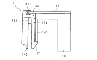
- FIG. 14 is a schematic top view showing the side end cover 1 in which the speaker protection plate 15 is inserted.
- FIG. 15 is a front perspective view showing the side end cover 1 and the speaker protection plate 15.
- the side end covers 1 and 1 are attached to both ends of the speaker protection plate 15, respectively. At that time, both side ends of the speaker protection plate 15 are sufficiently pushed into the bottom of the groove 34 of the side end cover 1. When the side end portion of the speaker protection plate 15 is inserted into the groove portion 34, the insertion portion 2 and the longitudinal direction of the speaker protection plate 15 are perpendicular to each other.
- the speaker protection plate 15 is sandwiched between the internal rib 311 and the front side surface of the groove 34. That is, the side edge of the speaker protection plate 15 and its vicinity are sandwiched between the inner surface of the second side wall 33 and the inner ribs 311, 311. Yes.
- the speaker protection plate 15 and the side end cover 1 are temporarily fixed in the front-rear direction, and the speaker protection plate 15 and the side end cover 1 can be operated as an integral part.
- the speaker protection plate 15 can slide in the left-right direction within the groove 34.
- FIG. 16 is a schematic top view showing the middle of insertion part 2 being inserted into insertion hole 14.
- An inner plate 141 that is provided inside the insertion hole 14 in the left-right direction and has a plate shape facing in the left-right direction, and an outer surface of the outer plate 142 that is provided outside the insertion hole 14 in the left-right direction and faces in the left-right direction, These correspond to the inner and outer surfaces of the insertion hole 14, respectively.
- the interval between the insertion holes 14 and 14 is wider than the interval between the insertion portions 2 and 2 of the side end cover integrated with the speaker protection plate 15. Therefore, when inserting the insertion portions 2 and 2 into the insertion holes 14 and 14, the insertion portions 2 and 2 are inserted so as to open outward.
- FIG. 17 is a schematic top view showing a state in which the positions of the mounting plate 10, the speaker protection plate 15, and the side end cover 1 are fixed. Since the interval between the insertion holes 14 and 14 is wider than the interval between the insertion portions 2 and 2 of the side end cover 1 and 1 integrated with the speaker protection plate 15, the attachment of the side end covers 1 and 1 is completed. The side end covers 1, 1 move in their respective outward directions, that is, in directions away from the speaker protection plate 15. Therefore, a space is generated between the side end portion of the speaker protection plate 15 and the bottom portions of the grooves 34 and 34, and the relationship between the speaker protection plate 15 and the side end covers 1 and 1 is in a loose-fitting state.
- the speaker protection plate 15 and the side end cover 1 can be loosely fitted after being attached in this manner, even if the speaker protection plate 15 expands or contracts in the left-right direction due to heat, the side end cover The position of 1 does not fluctuate in response to such expansion or contraction. If the speaker protection plate 15 and the side end cover 1 remain fixed in the left-right direction, the side end cover 1 also moves in the left-right direction as the speaker protection plate 15 expands and contracts. Thus, a step with the mounting plate 10 is generated.
- the inner protrusions 231, 231, 231 and the outer protrusions 241, 241 play a role of preventing rattling after the insertion is completed.
- the side end cover 1 is formed with a groove portion 34 extending in the left-right direction using the first side wall portion 31 extending in the left-right direction from the front end of the insertion portion 2. Is disposed outside the insertion holes 14 and 14 and sandwiches the side end portion of the speaker protection plate 15. Therefore, for example, when compared with a structure in which the mounting plate 10 from the rear at the side end portion of the speaker protection plate 15 is sandwiched by the cover from the front, the length of the speaker protection plate 15 is larger than the interval between the insertion holes 14 and 14. Can also be long. Further, the second side wall portion 33 can be made inconspicuous in the front view of the display device 90 by making the dimension in the left-right direction shorter than the first side wall portion 31.
- FIG. 18 is a front partial perspective view showing a state in which the positions of the mounting plate 10, the speaker protection plate 15, and the side end cover 1 are fixed.
- the left-right position of the insertion portion 2 in the insertion hole 14 is fixed by the thickness in the left-right direction of the inner protrusions 231, 231, 231 and the outer protrusions 241, 241.
- the partition plate 140 is arrange
- the display device 90 has a strip shape with the speakers 53 and 53, the speaker protection plate 15 provided in front of the speakers 53 and 53, and the mounting plate 10 for attaching the speaker protection plate 15 to the front surface.
- the mounting plate 10 has holes penetrating in the front-rear direction on both side portions in the longitudinal direction of the speaker protection plate 15, and side end portions on both sides in the longitudinal direction of the speaker protection plate 15.
- the side end cover 1 is provided with a groove portion 34 that sandwiches the speaker protection plate 15 from the front and rear directions, and the side end portion is inserted into the groove portion 34. Inserted into the cover 3 and 3 covering the side end portion and the hole, and the locking portion 21 provided at the front end locking the mounting plate 10 at the peripheral edge of the rear end of the hole. Part 2 To.
- the side end cover 1 that covers and covers the side end portion of the speaker protection plate 15 from the front-rear direction, the temperature change or the external force on the display device 90 is provided.
- the speaker protection plate 15 can be prevented from being detached from the mounting plate 10.
- the display device 90 according to the present embodiment is characterized in that the insertion portion 2 includes a protruding portion protruding toward the peripheral surface side of the hole.
- the insertion portion 2 can be easily inserted into the hole by having such a protruding portion. Further, since the protruding portion protrudes after the insertion portion 2 is inserted, the distance between the hole and the insertion portion is reduced in the longitudinal direction of the speaker protection plate 15, and the position is fixed.
- the display device 90 according to the present embodiment is characterized in that a rib is provided on the front surface of the groove 34 or the back surface of the groove 34, and the rib and the speaker protection plate 15 are in contact with each other.
- the width of the groove portion 34 in the front-rear direction is narrowed, so that the force of the groove portion 34 sandwiching the side end portion of the speaker protection plate 15 in the front-rear direction is strong.
- the speaker protection plate 15 since such a rib is provided, the width of the groove portion 34 in the front-rear direction is narrowed, so that the force of the groove portion 34 sandwiching the side end portion of the speaker protection plate 15 in the front-rear direction is strong.
- the speaker protection plate 15 from being detached from the mounting plate 10 due to a temperature change or an external force applied to the display device 90.
- the display device 90 according to the present embodiment is characterized in that the front surface of the groove portion 34 is shorter in the longitudinal direction than the back surface of the groove portion 34.
- the side end cover 1 when the display device 90 is viewed from the front, the side end cover 1 becomes inconspicuous, so that the speaker protection plate 15 is prevented from being detached from the mounting plate 10 while improving the aesthetic appearance. Can do.
- the display device 90 according to the present embodiment is characterized in that a gap is provided between the bottom of the groove 34 and the side end.
- the speaker protection plate 15 can be extended even in the longitudinal direction due to an increase in temperature. It is possible to prevent the protection plate 15 or the side end cover 1 from being deformed.
- the television receiver includes the above-described display device 90, a tuner that receives a television broadcast wave, and a display unit 62.
- the display unit 62 receives the television broadcast received by the tuner. An image based on waves is displayed.
- Second Embodiment A second embodiment will be described.
- the shapes of the side end cover 1 and the speaker protection plate 15 are different from those of the first embodiment.
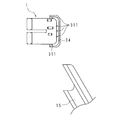
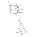
- 19 to 21 are a left side view of the side cover 1 and a partial rear perspective view of the speaker protection plate 15.
- the vertical cross section of the speaker protection plate 15 has a thin U-shaped cross-sectional shape in which the upper end and the lower end protrude forward with the same protruding amount and the center is flat.
- the front end of the insertion portion 2, the first side wall portion 31, the connection portion 32, and the second side wall portion 33, along the vertical cross section of the speaker protection plate 15, protrude forward with the same protrusion amount, and the center is flat. It has a shape.
- the groove 34 in the side end cover 1 has a shape along the longitudinal section of the speaker protection plate 15, and the side end of the speaker protection plate 15 is inserted into the groove 34.
- the internal ribs 311, 311... Are provided on the front, upper and lower sides of the first side wall portion 31, respectively, and many internal ribs 311 are arranged in the front portion where the contact with the speaker protection plate 15 is large.
- the side end cover 1 and the speaker protection plate 15 By making the side end cover 1 and the speaker protection plate 15 into the shape shown in FIG. 19, the whole can be seen thin and flat.
- the shape of the side end cover 1 and the speaker protection plate 15 shown in FIG. 19 is, for example, a case where large speakers 53, 53 are used in a large display device 90, and the speakers 53, 53 are not conspicuous, It is suitable when you want to give a sense of unity.
- the speaker protection plate 15 has a vertical cross section in which the center projects forward, and the center from the upper end and the center from the lower end form a straight line.
- the front end of the insertion portion 2, the first side wall portion 31, the connection portion 32, and the second side wall portion 33 are convex toward the front along the longitudinal section of the speaker protection plate 15. Therefore, the groove portion 34 in the side end cover 1 has a shape along the longitudinal section of the speaker protection plate 15, and the side end portion of the speaker protection plate 15 is inserted into the groove portion 34.
- a plurality of internal ribs 311, 311... Are provided at a distance from the portion excluding the apex of the first side wall portion 31.
- the reason why the inner ribs 311 and 311 are not provided at the apex of the side end cover 1 shown in FIG. 20 is that it fits with the side end cover 1 due to variations in the bending portion of the speaker protection plate 15 corresponding to the apex. This is because the state is likely to change and the positional relationship with the internal rib 311 is likely to change.
- the longitudinal section of the speaker protection plate 15 is such that the lower end protrudes forward from the upper end, the apex is provided at the lower end, and the upper end to the lower end is linear.
- the front end of the insertion portion 2, the first side wall portion 31, the connection portion 32, and the second side wall portion 33 have a shape along the longitudinal section of the speaker protection plate 15, and the lower end projects forward from the upper end and the apex is provided at the lower end.
- the upper end to the lower end are linear.
- the groove 34 in the side end cover 1 has a shape along the longitudinal section of the speaker protection plate 15, and the side end of the speaker protection plate 15 is inserted into the groove 34.
- a plurality of internal ribs 311, 311... Are provided at a distance from the portion excluding the apex of the first side wall portion 31.
- the side end cover 1 and the speaker protection plate 15 shown in FIG. 21 are, for example, a small display device 90 and are used when the vicinity of the speakers 53 and 53 is a part of a pedestal.
- a mounting plate is configured as a part of a housing, and holes penetrating the mounting plate are provided on both side ends in the longitudinal direction of the speaker protection plate.
- Side end covers are respectively provided at the side end portions on both sides in the longitudinal direction of the speaker protection plate.
- the side end cover is provided with a groove for sandwiching the speaker protection plate from the front and rear. In addition, the side end cover is inserted into the groove, so that the side end is inserted into the cover and the hole of the mounting plate.
- An insertion portion for locking the mounting plate at the periphery is provided.
- a speaker device in which the speaker protection plate can be locked to the mounting plate can be configured.
- an audio device including such a speaker device for example, a CD (Compact Disc) player, a music player, a radio, and the like can be configured.
Landscapes
- Engineering & Computer Science (AREA)
- Computer Hardware Design (AREA)
- Theoretical Computer Science (AREA)
- General Engineering & Computer Science (AREA)
- Physics & Mathematics (AREA)
- Human Computer Interaction (AREA)
- General Physics & Mathematics (AREA)
- Multimedia (AREA)
- Signal Processing (AREA)
- Mathematical Physics (AREA)
- Devices For Indicating Variable Information By Combining Individual Elements (AREA)
- Details Of Audible-Bandwidth Transducers (AREA)
Abstract
温度変化又は表示装置に対する外力等によって、スピーカ保護板が取付板から外れることを防止する表示装置を提供する。 スピーカと、帯状をなし、該スピーカの前方に設けられたスピーカ保護板15と、該スピーカ保護板15を前面に取り付ける取付板10とを備える表示装置において、前記取付板10は、前後方向に貫通した孔を前記スピーカ保護板15の長手方向における両側部に有し、前記スピーカ保護板15の長手方向における側端部が挿入されており、前記スピーカ保護板15を前後方向から挟む溝部34が設けられ、該溝部34によって前記側端部を覆う覆部3、3、及び前記孔に挿入し、先端に設けられた係止部21が前記孔の後端周縁にて前記取付板10を係止する挿入部を有する側端覆体1が、前記スピーカ保護板15の両側端部に夫々設けられていることを特徴とする。
Description
本発明は、スピーカと該スピーカの前方に保護板が設けられた表示装置に関する。
表示装置において、スピーカを保護するため、スピーカの前方に金属製の網板等の板状のスピーカ保護板が設けられることがある。このような保護板を用いる場合、表示装置に美観を持たせるため、スピーカ保護板の側部を覆体によって覆うことがある。
しかし、特許文献1に記載されているような構造を用いて表示装置にスピーカ保護板を取り付ける場合には、温度変化又は表示装置に対する外力等による影響を受け、スピーカ保護板が覆体から外れるという問題が生じる。
本発明は斯かる事情に鑑みてなされたものであり、温度変化又は表示装置に対する外力等によって、スピーカ保護板が取付板から外れることを防止する表示装置を提供することを目的とする。
本発明に係る表示装置は、スピーカと、帯状をなし、該スピーカの前方に設けられたスピーカ保護板と、該スピーカ保護板を前面に取り付ける取付板とを備える表示装置において、前記取付板は、前後方向に貫通した孔を前記スピーカ保護板の長手方向における両側部に有し、前記スピーカ保護板の長手方向における両側の側端部に、夫々側端覆体が設けられており、該側端覆体は、前記スピーカ保護板を前後方向から挟む溝部が設けられており、該溝部に前記側端部が挿入されることによって前記側端部を覆う覆部と、前記孔に挿入し、先端に設けられた係止部が前記孔の後端周縁にて前記取付板を係止する挿入部とを有することを特徴とする。
本発明に係る表示装置は、前記挿入部は、前記孔の周面側に突出している突出部を備えることを特徴とする。
本発明に係る表示装置は、前記溝部前面又は溝部背面にはリブが設けられており、該リブと前記スピーカ保護板とが接触していることを特徴とする。
本発明に係る表示装置は、前記溝部前面は前記溝部背面よりも前記長手方向の長さが短いことを特徴とする。
本発明に係る表示装置は、前記溝部の底部と前記側端部との間には、間隙が設けられていることを特徴とする。
本発明に係るテレビジョン受信機は、上述の表示装置と、テレビジョン放送波を受信するチューナと、表示部とを備え、前記表示部は、前記チューナが受信したテレビジョン放送波に基づく映像を表示することを特徴とする。
本発明によれば、スピーカ保護板の側端を前後方向から挟んで覆い、かつ取付板に係止する側端覆体を設けることにより、温度変化又は表示装置に対する外力等によって、スピーカ保護板が取付板から外れることを防止することができる。
第1の実施の形態
本実施の形態における表示装置90について説明する。図1は表示装置90を示す前面斜視図である。表示装置90は、フレーム61、表示部62、チューナ基板51及び制御基板52を備える。以下において、図1における上下方向を上下方向、左右方向を左右方向、手前方向を前方、奥方向を後方とする。
本実施の形態における表示装置90について説明する。図1は表示装置90を示す前面斜視図である。表示装置90は、フレーム61、表示部62、チューナ基板51及び制御基板52を備える。以下において、図1における上下方向を上下方向、左右方向を左右方向、手前方向を前方、奥方向を後方とする。
表示部62は表示画面を前面に有する横長の矩形板状をなした液晶パネルであり、表示画面に映像が表示される。
表示装置90の背面側にはチューナ基板51と、制御基板52とが設けられている。チューナ基板51は、チューナを備える。表示装置90は、チューナ基板51のチューナより受信したテレビジョン放送に基づいて、表示部62に映像を表示するテレビジョン受信機として機能する。制御基板52はCPU(Central Processing Unit)を備え、表示部62を電気的に制御する。
さらに、表示装置90の下方における両端付近には、スピーカ53、53が夫々設けられている。スピーカ53、53は、チューナ基板51のチューナより受信したテレビジョン放送に基づいて放音する。
図2は、表示装置90を示す分解斜視図である。表示装置90は、さらにフレーム61、表示部62、光学シート63、枠体64、導光板65、反射シート66、発光部67、放熱体68及びバックライトシャーシ80を備える。
フレーム61はアルミニウム製であり、断面がL字状をなした4本の杆体の端部が夫々連結することにより、横長の矩形状の枠体をなす。表示部62は、前面側の周縁がフレーム61と周に沿って接触している。
光学シート63は、表示部62の背面側に設けられている。光学シート63は、合成樹脂製であって横長の略矩形板状をなしており、複数枚が前後方向に積層されている。各光学シート63は夫々、プリズムシート、拡散シート又は反射偏光シート等である。
枠体64は、樹脂製である4本の杆体の端部が夫々連結することにより、横長の矩形状の枠体をなす。枠体64は、光学シート63の端部を係止して、光学シート63の位置を光学シート63の背面側から保持している。
導光板65は、表示部62と略同形状の横長略矩形状をなしており、枠体64の背面側に設けられている。導光板65は、発光部67から内部に入射された光を出射する。
反射シート66は、導光板65とバックライトシャーシ80との間に配設される横長矩形状のシートである。反射シート66は、導光板65の背面と略同一の形状をなす。反射シート66は、導光板65の背面に配置されており、導光板65から出射される光のうち、背面側に出射された光を前面側に反射する。
発光部67、67は、複数のLED光源が長手方向に直線状に配列され、全体として杆体をなしている。発光部67、67は、上端及び下端に夫々、導光板65の長手方向と平行であって、発光部67、67の光源同士が対向するように配置されている。斯かる配置により、発光部67、67は夫々光を出射し、出射された光は、導光板65の上側面及び下側面から内部に向かう。
放熱体68、68は、杆体をなし、導光板65の上端及び下端に、導光板65の長手方向と平行になるように夫々配置されている。放熱体68、68は、発光部67、67を支持しており、発光部67、67に溜まった熱を放熱する。
バックライトシャーシ80は、金属製の箱状であり、底面が横長の矩形板状をなす。表示部62は、背面側の周縁が枠体64と接触しており、前面が表示面となるように位置が固定される。光学シート63は、導光板65を介して発光部67、67から発せられる光を均一に拡散する。
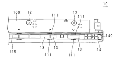
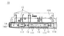
図3は、バックライトシャーシ80及び取付板10を示す背面側の分解斜視図である。図4は、取付板10を示す部分正面図である。図5は、取付板10の部分背面図である。図5は、図4が示す取付板10の部分の背面側を示している。図4及び図5は、取付板10の正面視右側の一部の前面及び背面を示したものである。
バックライトシャーシ80は、導光板65の背面側に設けられており、取付板10と接合している。バックライトシャーシ80は、金属製の箱状であり、横長の矩形板状をなす。バックライトシャーシ80は、背面側の下方に、螺子孔82、82…が設けられている。また、バックライトシャーシ80の背面側の下方には、左右方向に対称な位置に2カ所、上下方向に沿って背面側に凸状をなしている金属製の凸状部材81、81が取り付けられている。従って、凸状部材81、81がバックライトシャーシ80の背面に螺子止めされることにより、バックライトシャーシ80及び凸状部材81、81によって、下側が開口し、上下方向に長い空洞を形成する。
取付板10は、左右方向の長さがバックライトシャーシ80の左右方向の長さに略等しく、上下方向の長さが表示部62より短い樹脂製の板部材である。取付板10は、シャーシ設置板100及び突出部110を備える。シャーシ設置板100は、左右方向に長い略平板状をなし、表示装置90の前後方向に面するように配置されている。シャーシ設置板100はさらに、係止爪11、11及び貫通孔12、12…を備える。
係止爪11は、シャーシ設置板100の上端から上方に突出している。係止爪11は、凸状部材81、81同士の間隔と等しい間隔を置いた位置に2カ所設けられている。また、貫通孔12は、前後方向に貫通しており、シャーシ設置板100全体に間隔を空けて設けられている。係止爪11、11は、バックライトシャーシ80及び凸状部材81により形成された空洞に挿入される。係止爪11、11は、凸状部材81、81の開口に挿入されることにより、バックライトシャーシ80が取付板10の前面側の上方と接するように位置が固定される。
また、貫通孔12、12…及び螺子孔82、82…には、螺子が貫通される。これにより、取付板10及びバックライトシャーシ80の位置が固定される。
取付板10における下部には、左右方向に沿って前面側に突出している突出部110が設けられている。突出部110は、矩形孔13及び挿入孔14を備える。突出部110の前面側における両側には、矩形孔13、13…が、左右方向に沿って夫々複数設けられている。矩形孔13、13…は、スピーカ53、53の前方に設けられている。
矩形孔13、13…によって前後方向が開放されていることにより、取付板10の背面側に設けられたスピーカ53、53が放つ音が前面側に届きやすくなる。また、突出部10の上方及び下方には、夫々、左右方向全体に亘って細長い取付孔111、111…が間隔を置いて複数設けられている。
突出部110には、矩形孔13、13…よりも側端に近い側に、上下方向に長く、左右方向の幅が狭い挿入孔14が前後方向に設けられている。挿入孔14は左右方向及び上下方向の大きさが、深さ方向である前後方向の位置によらずほぼ一定である。挿入孔14の上下方向中央には、左右方向に延びた板状の仕切板140が設けられており、挿入孔14が上下に仕切られている。
図4及び図5は、正面視右側の挿入孔14について示しているが、左右方向に対称な位置にも、挿入孔14と左右対称な位置に、左右対称な形状をなす挿入孔14が設けられている。
図6は、側端覆体1、取付板10及びスピーカ保護板15を示す前面斜視図である。図7は、側端覆体1、取付板10及びスピーカ保護板15を示す前面分解斜視図である。表示装置90において、取付板10の下方前面にはスピーカ保護板15が設けられており、下方側面には、側端覆体1が設けられている。側端覆体1、取付板10及びスピーカ保護板15は夫々分離可能である。
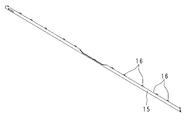
図8は、スピーカ保護板15の前面斜視図である。図9は、スピーカ保護板15の背面斜視図である。スピーカ保護板15は、突起16を備える。スピーカ保護板15は、断面が前面側に凸である略弧状をなした杆体である。スピーカ保護板15は例えばアルミニウム等の金属製であり網目が全面に設けられたパンチングネットであるが、樹脂製であってもよく、その他の材質であってもよい。また、スピーカ保護板15は、パンチングネットのような網目状でなくともよい。スピーカ保護板15の長手方向の長さは、2つの挿入孔14、14の間隔よりも長い。スピーカ保護板15は、外力が加わらない状態では自身の形状を維持できる材質である。
スピーカ保護板15は、左右方向である長手方向に略直線状をなしている。また、長手方向中央部分は、短手方向の一端から内部に凹部が設けられている。従ってスピーカ保護板15は、中央部分が他の部分より細くなっている。
スピーカ保護板15は、上端及び下端に、夫々長手方向に沿って間隔を置いた複数の突起16、16…が設けられている。スピーカ保護板15における上側及び下側夫々の側端付近に設けられた突起16、16…の形状は、基部より先端の方が長手方向に幅が広い形状をなしている。スピーカ保護板15における上側下側夫々の中央側に設けられた突起16、16…は、平面視略台形状をなし、中央に孔が設けられた板状をなしている。突起16、16…は、上下方向に面しており、後側に向かって突出している。
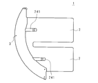
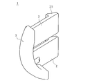
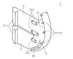
側端覆体1について説明する。側端覆体1は樹脂製であり、可撓性を有する。図10は、側端覆体1を示す左側面図である。図11は、側端覆体1を示す右側面図である。図12は、側端覆体1を示す左前面斜視図である。図13は、側端覆体1を示す右前面斜視図である。側端覆体1は表示装置90の両側に夫々設けられているが、図10から図13までは、正面視右側の側端覆体1を示している。正面視左側の側端覆体1は、正面視右側の側端覆体1と、左右方向を向いた面に対して対称である他は、正面視右側の側端覆体1と同じ形状をなす。
側端覆体1は、板状の挿入部2及び該挿入部2の外側面の前端から外側方向に延びた覆部3を備える。覆部3は、第1側壁部31、接続部32、第2側壁部33、リブである内部リブ311、311…を備える。
第1側壁部31は左右方向の長さが一定であり、上下方向の断面が、スピーカ保護板15の断面に沿って前方に凸になるように曲がった曲板である。第1側壁部31は、面が前後方向を向くように配置されている。
第1側壁部31の前方の面には、内部リブ311、311…が設けられている。内部リブ311、311…は左右方向に延びた細長い形状をなしており、前方の面の上下方向に沿って間隔を置いて設けられている。また、第1側壁部31は、外側の端が接続部32に繋がっている。
接続部32は、第1側壁部31の外側と周に沿って接続されている曲板である。接続部32は、上下方向に延びた形状をなし、左右方向に面した帯状をなしている。接続部32は、前方である幅方向が凸になるように、スピーカ保護板15の断面の形状に従って前後方向に曲がった曲板である。
第2側壁部33は、接続部32の前側と周に沿って接続されている曲板である。第2側壁部33は左右方向の幅が一定であり、スピーカ保護板15の断面に沿って前方に凸になるように曲がった曲板である。第1側壁部31は、面が前後方向を向くように配置されている。第2側壁部33は、第1側壁部31と平行になるように前後方向に配列されている。また、第2側壁部33は、第1側壁部31より左右方向の長さが短い。
第1側壁部31、接続部32及び第2側壁部33により、左右方向の内側から外側に向かう溝部34が形成される。溝部34は、開口部がスピーカ保護板15の側面に沿っており、スピーカ保護板15の側面よりも幅が広い形状をなしている。また、溝部34の幅及び長さは溝部34の深さによらず一定である。
なお、本実施の形態では、溝部34を形成している第1側壁部31の前面には、内部リブ311、311…が設けられ、第2側壁部32の後面にはリブ内部リブ311、311には設けられていない。しかし、第2側壁部32の後面に内部リブ311、311…が設けられていてもよい。また、その場合、第1側壁部31の前面には、内部リブ311、311…が設けられていても、設けられていなくてもよい。
挿入部2は、板状をなし、両面が左右方向を向いている。挿入部2は、上側、後側及び下側の周縁が夫々直線状をなし、上側の周縁と後側の周縁、及び後側の周縁と下側の周縁とは直角をなしている挿入部2の前方は、スピーカ保護板15の断面に沿った弧状の周縁を有している。
また、挿入部2は、上下2つに分離しており、内側面後方には、係止部21が設けられている。係止部21は、表示装置の左右方向内側に向けて突出しており、後端が薄く前方が厚くなるような厚みをなしている。従って、係止部21は前後方向を係止可能な構造になっている。
挿入部2の内側面前方には、内側突出部231、231、231が設けられている。内側突出部231、231、231は、上下方向に間隔を置いて並置されており、夫々前後方向に延びた略矩形状をなしている。内側突出部231は、中央の内側突出部231、下方の内側突出部231、上方の内側突出部231の順に前後方向の長さが長いが、後端の位置は一致している。内側突出部231、231、231は、後方が、後端から前方に向かうに連れて突出量が大きくなる斜面をなしており、頂面の中央部分が平坦である。
挿入部2の外側面前方には、外側突出部241、241が設けられている。外側突出部241は、上下に分離した挿入部2の上側中央に設けられており、外側突出部241は、下側中央に夫々設けられている。外側突出部241、241は、前後方向に延びた細長い形状をなしている。外側突出部241、241は、後方が、後端から前方に向かうに連れて突出量が大きくなる斜面をなしており、中央から前方にかけては、平坦な形状をなしている。また、外側突出部241、241の前端は、第1側壁部31の裏側と繋がっている。
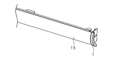
続いて、側端覆体1及びスピーカ保護板15が取付板10に取り付けられる様子を示す。図14は、スピーカ保護板15が挿入された側端覆体1を示す模式的上面図である。図15は、側端覆体1及びスピーカ保護板15を示す前面斜視図である。
側端覆体1、1は、スピーカ保護板15の両側端に夫々取りつけられる。その際、スピーカ保護板15の両側端を、側端覆体1の溝部34の底部にまで十分に押しこむ。スピーカ保護板15の側端部が溝部34に挿入されることにより、挿入部2とスピーカ保護板15の長手方向とが垂直をなす。
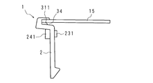
すると、内部リブ311と溝部34の前方の側面とによって、スピーカ保護板15が挟持される。即ち、スピーカ保護板15の側端及びその近傍は、第2側壁部33の内面と第1側壁部31の内面に設けられた内部リブ311、311…とにより、前後方向に隙間なく挟まれている。これにより、スピーカ保護板15と側端覆体1とは前後方向に仮固定された状態となり、スピーカ保護板15と側端覆体1とは、一体の部品として作業ができる。一方、スピーカ保護板15は溝部34内において、左右方向には摺動可能である。
図16は、挿入部2が挿入孔14に挿入される途中を示す模式的上面図である。挿入孔14の左右方向内側に設けられ左右方向に面した板状をなす内側板141、及び挿入孔14の左右方向外側に設けられ左右方向に面した板状をなす外側板142の外面が、夫々挿入孔14の内面及び外面にあたる。
挿入孔14、14の間隔は、スピーカ保護板15と一体となった側端覆体の挿入部2、2の間隔より広い。そのため、挿入孔14、14に挿入部2,2を挿入する際は、挿入部2、2が外側に開く様に挿入されていく。
図17は、取付板10、スピーカ保護板15及び側端覆体1の位置が固定された状態を示す模式的上面図である。挿入孔14、14の間隔は、スピーカ保護板15と一体となった側端覆体1、1の挿入部2、2の間隔より広いことから、側端覆体1、1の取付が完了すると、側端覆体1、1は、夫々の外側方向、即ち、スピーカ保護板15から離れる方向に移動する。そのため、スピーカ保護板15の側端部と、溝部34、34の底部との間に間隔が生じ、スピーカ保護板15と側端覆体1、1との関係は遊嵌状態となる。
このように取付後には、スピーカ保護板15と側端覆体1とを遊嵌状態とすることができるので、スピーカ保護板15が熱により左右方向に膨張又は収縮したとしても、側端覆体1が斯かる膨張又は収縮に応じて位置が変動することがない。もし、スピーカ保護板15と側端覆体1とが左右方向にも固定されたままであると、スピーカ保護板15の膨張、収縮に応じて、側端覆体1も左右方向に移動することになり、取付板10との段差が発生することになる。なお、内側突出部231、231、231及び外側突出部241、241は、挿入完了後のガタつき防止の役割を果たす。
このように、取付時には、内部リブ311及び溝部34によって、スピーカ保護板15と側端覆体1、1とを一体化することで作業性を向上させることができる。また、スピーカ保護板15と側端覆体1、1とを一体化した際の挿入部2、2の間隔を、取付板10の挿入孔14、14の間隔よりも狭くすることによって製品外観の品位を保つことができる。
加えて、側端覆体1は、上述した通り、挿入部2の前端から左右方向に延びた第1側壁部31を用いて、左右方向に延びた溝部34が形成されており、該溝部34は、挿入孔14、14よりも外側に配置されて、スピーカ保護板15の側端部を挟持する。従って、例えば、スピーカ保護板15の側端部における後方から取付板10が、前方から覆体が挟む構造等と比較した場合、スピーカ保護板15の長さを、挿入孔14、14の間隔よりも長くすることができる。さらに、第2側壁部33は、第1側壁部31よりも左右方向の寸法を短くすることにより、表示装置90の正面視において、側端覆体1を目立たなくすることができる。
図18は、取付板10、スピーカ保護板15及び側端覆体1の位置が固定された状態を示す前面部分斜視図である。また、挿入部2に加え、内側突出部231、231、231及び外側突出部241、241の左右方向の厚みにより、挿入孔14内での挿入部2の左右方向の位置が固定される。
また、挿入部2を挿入孔14に挿入することにより、左右方向について、側端覆体1が取付板10に固定される。これにより、溝部34の底部とスピーカ保護板15の側端との間に隙間が設けられる。これにより、スピーカ保護板15の温度が上昇した場合であっても、スピーカ保護板15又は側端覆体1が変形することなく伸縮することができる。なお、挿入部2が二つに分離することにより形成されている凹部には、仕切板140が配置されて、上下方向の位置が固定される。
本実施の形態に係る表示装置90は、スピーカ53、53と、帯状をなし、該スピーカ53、53の前方に設けられたスピーカ保護板15と、該スピーカ保護板15を前面に取り付ける取付板10とを備える表示装置90において、前記取付板10は、前後方向に貫通した孔を前記スピーカ保護板15の長手方向における両側部に有し、前記スピーカ保護板15の長手方向における両側の側端部に、夫々側端覆体1が設けられており、該側端覆体1は、前記スピーカ保護板15を前後方向から挟む溝部34が設けられており、該溝部34に前記側端部が挿入されることによって前記側端部を覆う覆部3、3と、前記孔に挿入し、先端に設けられた係止部21が前記孔の後端周縁にて前記取付板10を係止する挿入部2とを有することを特徴とする。
本実施の形態によれば、スピーカ保護板15の側端部を前後方向から挟んで覆い、かつ取付板10に係止する側端覆体1を設けることにより、温度変化又は表示装置90に対する外力等によって、スピーカ保護板15が取付板10から外れることを防止することができる。
本実施の形態に係る表示装置90は、前記挿入部2は、前記孔の周面側に突出している突出部を備えることを特徴とする。
本実施の形態によれば、斯かる突出部を有することにより、挿入部2を孔に挿入することが容易になる。また、挿入部2を挿入した後、突出部が突出していることにより、スピーカ保護板15の長手方向において、孔と挿入部との間隔が狭まり、位置が固定されるようになる。
本実施の形態に係る表示装置90は、前記溝部34前面又は溝部34背面にはリブが設けられており、該リブと前記スピーカ保護板15とが接触していることを特徴とする。
本実施の形態によれば、斯かるリブが設けられていることにより、溝部34の前後方向における幅が狭くなるため、溝部34がスピーカ保護板15の側端部を前後方向に挟む力が強くなり、温度変化又は表示装置90に対する外力等によって、スピーカ保護板15が取付板10から外れることを防止することができる。
本実施の形態に係る表示装置90は、前記溝部34前面は前記溝部34背面よりも前記長手方向の長さが短いことを特徴とする。
本実施の形態によれば、表示装置90を正面から見た場合に、側端覆体1が目立たなくなるため、美観を向上させながら、スピーカ保護板15が取付板10から外れることを防止することができる。
本実施の形態に係る表示装置90は、前記溝部34の底部と前記側端部との間には、間隙が設けられていることを特徴とする。
本実施の形態によれば、溝部34の底部と側端部との間に間隙が設けられていることにより、スピーカ保護板15が温度の上昇により長手方向に伸長した場合であっても、スピーカ保護板15又は側端覆体1が変形することを防止することができる。
本実施の形態に係るテレビジョン受信機は、上述の表示装置90と、テレビジョン放送波を受信するチューナと、表示部62とを備え、前記表示部62は、前記チューナが受信したテレビジョン放送波に基づく映像を表示することを特徴とする。
第2の実施の形態
第2の実施の形態について説明する。本実施の形態は、側端覆体1及びスピーカ保護板15の形状が第1の実施の形態と異なる。図19~図21は、側部覆体1の左側面図及びスピーカ保護板15の部分背面斜視図である。
第2の実施の形態について説明する。本実施の形態は、側端覆体1及びスピーカ保護板15の形状が第1の実施の形態と異なる。図19~図21は、側部覆体1の左側面図及びスピーカ保護板15の部分背面斜視図である。
図19は、スピーカ保護板15の縦断面が、上端及び下端が同じ突出量で前方に突出し、中央が平坦な薄いコの字断面形状をなしている。挿入部2の前端、第1側壁部31、接続部32及び第2側壁部33は、スピーカ保護板15の縦断面に沿った、上端及び下端が同じ突出量で前方に突出し、中央が平坦な形状をなしている。従って、側端覆体1における溝部34は、スピーカ保護板15の縦断面に沿った形状をなしており、斯かる溝部34にスピーカ保護板15の側端部が挿入される。内部リブは311、311…は、第1側壁部31の前方、上方及び下方に夫々設けられているところ、スピーカ保護板15との接触が多い前方部分に、内部リブ311が多く配置される。
側端覆体1及びスピーカ保護板15を、図19に示す形状とすることで、全体を薄くフラットに見せることができる。図19に示す側端覆体1及びスピーカ保護板15の形状は、例えば、大型の表示装置90に、大型のスピーカ53、53を用いる場合であって、スピーカ53、53を目立たせず、全体として統一感を持たせたいときに好適である。
図20は、スピーカ保護板15の縦断面が、中央が前方に向かって突出しており、上端から中央及び下端から中央の夫々が直線状をなした形状をなしている。挿入部2の前端、第1側壁部31、接続部32及び第2側壁部33は、スピーカ保護板15の縦断面に沿った、前方に向かって凸状をなしている。従って、側端覆体1における溝部34が、スピーカ保護板15の縦断面に沿った形状をなしており、斯かる溝部34にスピーカ保護板15の側端部が挿入される。内部リブは311、311…は、第1側壁部31の頂点を除いた部分に距離を置いて複数設けられている。図20に示す側端覆体1について、内部リブ311、311が頂点に設けられない理由は、頂点に対応するスピーカ保護板15の曲げ部の成形ばらつきによって、側端覆体1との嵌合状態が変化しやすく、内部リブ311との位置関係も変化しやすいからである。
図21は、スピーカ保護板15の縦断面が、下端が上端より前方に突出して頂点が下端に設けられており、上端から下端までが直線状をなしている。挿入部2の前端、第1側壁部31、接続部32及び第2側壁部33は、スピーカ保護板15の縦断面に沿った形状をなし、下端が上端より前方に突出して頂点が下端に設けられており、上端から下端までが直線状をなしている。従って、側端覆体1における溝部34は、スピーカ保護板15の縦断面に沿った形状をなしており、斯かる溝部34にスピーカ保護板15の側端部が挿入される。内部リブは311、311…は、第1側壁部31の頂点を除いた部分に距離を置いて複数設けられている。
図21に示す側端覆体1及びスピーカ保護板15は、例えば小型の表示装置90であって、スピーカ53、53付近を台座の一部とする場合に用いられる。
第1の実施形態及び第2の実施形態では、表示装置90における取付板10にスピーカ保護板15を係止する構造について述べたが、当該構造は表示装置90以外にも適用可能である。例えば、サウンドバーなどのスピーカ装置において、取付板を筐体の一部として構成し、当該取付板に貫通した孔を、スピーカ保護板の長手方向の両側に側端部に設ける。スピーカ保護板の長手方向の両側の側端部に夫々側端覆体を設ける。側端覆体には、スピーカ保護板を前後方向から挟む溝部を設ける。また側端覆体には、溝部に側端部が挿入されることによって、側端部を覆う覆部と、取付板の孔に挿入し、先端に設けられた係止部が孔の後縁周縁にて取付板を係止する挿入部とを設ける。以上により、第1の実施形態及び第2の実施形態と同様に、スピーカ保護板が取付板に係止可能なスピーカ装置が構成可能となる。また、このようなスピーカ装置を備えるオーディオ装置、例えば、CD(Compact Disc)プレーヤ、音楽プレーヤ、ラジオなども構成可能である。
今回開示された実施の形態はすべての点で例示であって、制限的なものでは無いと考えられるべきである。本発明の範囲は、上記した意味では無く、請求の範囲によって示され、請求の範囲と均等の意味及び範囲内でのすべての変更が含まれることが意図される。
1 側端覆体
2 挿入部
21 係止部
231 内側突出部
241 外側突出部
3 覆部
31 第1側壁部
311 内部リブ
32 接続部
33 第2側壁部
34 溝部
10 取付板
100 シャーシ設置板
110 突出部
111 取付孔
11 係止爪
12 貫通孔
13 矩形孔
14 挿入孔
140 仕切板
141 内側板
142 外側板
15 スピーカ保護板
16 突起
51 チューナ基板
52 制御基板
53 スピーカ
61 フレーム
62 表示部
63 光学シート
64 枠体
65 導光板
66 反射シート
67 発光部
68 放熱体
80 バックライトシャーシ
81 凸状部材
82 螺子孔
90 表示装置
2 挿入部
21 係止部
231 内側突出部
241 外側突出部
3 覆部
31 第1側壁部
311 内部リブ
32 接続部
33 第2側壁部
34 溝部
10 取付板
100 シャーシ設置板
110 突出部
111 取付孔
11 係止爪
12 貫通孔
13 矩形孔
14 挿入孔
140 仕切板
141 内側板
142 外側板
15 スピーカ保護板
16 突起
51 チューナ基板
52 制御基板
53 スピーカ
61 フレーム
62 表示部
63 光学シート
64 枠体
65 導光板
66 反射シート
67 発光部
68 放熱体
80 バックライトシャーシ
81 凸状部材
82 螺子孔
90 表示装置
Claims (6)
- スピーカと、帯状をなし、該スピーカの前方に設けられたスピーカ保護板と、該スピーカ保護板を前面に取り付ける取付板とを備える表示装置において、
前記取付板は、前後方向に貫通した孔を前記スピーカ保護板の長手方向における両側に有し、
前記スピーカ保護板の長手方向における両側の側端部に、夫々側端覆体が設けられており、
該側端覆体は、前記スピーカ保護板を前後方向から挟む溝部が設けられており、該溝部に前記側端部が挿入されることによって前記側端部を覆う覆部と、前記孔に挿入し、先端に設けられた係止部が前記孔の後端周縁にて前記取付板を係止する挿入部とを有する
ことを特徴とする表示装置。 - 前記挿入部は、前記孔の周面側に突出している突出部を備える
ことを特徴とする請求項1に記載の表示装置。 - 前記溝部前面又は溝部背面にはリブが設けられており、
該リブと前記スピーカ保護板とが接触している
ことを特徴とする請求項1又は2に記載の表示装置。 - 前記溝部前面は前記溝部背面よりも前記長手方向の長さが短い
ことを特徴とする請求項3に記載の表示装置。 - 前記溝部の底部と前記側端部との間には、間隙が設けられている
ことを特徴とする請求項1から4までのいずれか一つに記載の表示装置。 - スピーカと、帯状をなし、該スピーカの前方に設けられたスピーカ保護板と、該スピーカ保護板を前面に取り付ける取付板とを備えるスピーカ装置において、
前記取付板は、前後方向に貫通した孔を前記スピーカ保護板の長手方向における両側に有し、
前記スピーカ保護板の長手方向における両側の側端部に、夫々側端覆体が設けられており、
該側端覆体は、前記スピーカ保護板を前後方向から挟む溝部が設けられており、該溝部に前記側端部が挿入されることによって前記側端部を覆う覆部と、前記孔に挿入し、先端に設けられた係止部が前記孔の後端周縁にて前記取付板を係止する挿入部とを有する
ことを特徴とするスピーカ装置。
Applications Claiming Priority (2)
| Application Number | Priority Date | Filing Date | Title |
|---|---|---|---|
| JP2013-230555 | 2013-11-06 | ||
| JP2013230555A JP5800880B2 (ja) | 2013-11-06 | 2013-11-06 | 表示装置 |
Publications (1)
| Publication Number | Publication Date |
|---|---|
| WO2015068698A1 true WO2015068698A1 (ja) | 2015-05-14 |
Family
ID=53041475
Family Applications (1)
| Application Number | Title | Priority Date | Filing Date |
|---|---|---|---|
| PCT/JP2014/079254 Ceased WO2015068698A1 (ja) | 2013-11-06 | 2014-11-04 | 表示装置 |
Country Status (2)
| Country | Link |
|---|---|
| JP (1) | JP5800880B2 (ja) |
| WO (1) | WO2015068698A1 (ja) |
Citations (7)
| Publication number | Priority date | Publication date | Assignee | Title |
|---|---|---|---|---|
| JPS63287883A (ja) * | 1987-05-20 | 1988-11-24 | 松下電器産業株式会社 | フィルタ−取付け装置 |
| JPH0763966A (ja) * | 1993-08-24 | 1995-03-10 | Nec Corp | フィルタ保持機構 |
| JP2004069822A (ja) * | 2002-08-02 | 2004-03-04 | Sony Corp | 平面型画像表示装置 |
| US20080094542A1 (en) * | 2006-10-23 | 2008-04-24 | Jong-Hyeok Kim | Liquid crystal display device |
| JP2008167337A (ja) * | 2006-12-29 | 2008-07-17 | Sony Corp | スピーカ装置及びスピーカ付表示装置 |
| WO2009025035A1 (ja) * | 2007-08-22 | 2009-02-26 | Fujitsu Limited | スピーカの取り付け構造およびフラットパネルディスプレイ |
| JP2012068328A (ja) * | 2010-09-21 | 2012-04-05 | Orion Denki Kk | 表示装置 |
-
2013
- 2013-11-06 JP JP2013230555A patent/JP5800880B2/ja not_active Expired - Fee Related
-
2014
- 2014-11-04 WO PCT/JP2014/079254 patent/WO2015068698A1/ja not_active Ceased
Patent Citations (7)
| Publication number | Priority date | Publication date | Assignee | Title |
|---|---|---|---|---|
| JPS63287883A (ja) * | 1987-05-20 | 1988-11-24 | 松下電器産業株式会社 | フィルタ−取付け装置 |
| JPH0763966A (ja) * | 1993-08-24 | 1995-03-10 | Nec Corp | フィルタ保持機構 |
| JP2004069822A (ja) * | 2002-08-02 | 2004-03-04 | Sony Corp | 平面型画像表示装置 |
| US20080094542A1 (en) * | 2006-10-23 | 2008-04-24 | Jong-Hyeok Kim | Liquid crystal display device |
| JP2008167337A (ja) * | 2006-12-29 | 2008-07-17 | Sony Corp | スピーカ装置及びスピーカ付表示装置 |
| WO2009025035A1 (ja) * | 2007-08-22 | 2009-02-26 | Fujitsu Limited | スピーカの取り付け構造およびフラットパネルディスプレイ |
| JP2012068328A (ja) * | 2010-09-21 | 2012-04-05 | Orion Denki Kk | 表示装置 |
Also Published As
| Publication number | Publication date |
|---|---|
| JP2015090441A (ja) | 2015-05-11 |
| JP5800880B2 (ja) | 2015-10-28 |
Similar Documents
| Publication | Publication Date | Title |
|---|---|---|
| CN101212824B (zh) | 扬声器装置及带扬声器的显示装置 | |
| JP5104770B2 (ja) | バックライト装置 | |
| JP5166613B1 (ja) | 表示装置、及びテレビジョン受信機 | |
| JP4955063B2 (ja) | スピーカの取り付け構造およびフラットパネルディスプレイ | |
| US8197114B2 (en) | Chassis for an illuminating unit, and an illuminating unit, a display device and a television receiver incorporating the chassis | |
| JP6167629B2 (ja) | 表示装置 | |
| JP5800880B2 (ja) | 表示装置 | |
| CN107302674A (zh) | 液晶电视机 | |
| CN107272243A (zh) | 液晶显示设备 | |
| JP2014186053A (ja) | 表示装置 | |
| JP2011215867A (ja) | タッチパネルの取付構造および電子機器 | |
| WO2018158954A1 (ja) | 表示装置 | |
| KR101590642B1 (ko) | 디스플레이 장치 | |
| JP5029413B2 (ja) | バックライト装置 | |
| JP2008243558A (ja) | バックライト装置 | |
| JP2008204842A (ja) | バックライト装置 | |
| JP2008257952A (ja) | バックライト装置 | |
| US20150260393A1 (en) | Audio Equipment and Bracket for Linear Lighting Device Thereof | |
| JP2015090815A (ja) | 表示装置 | |
| JP6475782B2 (ja) | 表示装置およびテレビジョン受信機 | |
| KR101856162B1 (ko) | 차량용 화상표시장치 | |
| JP7140703B2 (ja) | 表示装置の取付構造 | |
| JP2019144398A (ja) | 表示装置及びテレビジョン受像機 | |
| WO2016047275A1 (ja) | 表示装置およびテレビジョン受像機 | |
| JP6653132B2 (ja) | 光源装置、表示装置及びテレビジョン受信機 |
Legal Events
| Date | Code | Title | Description |
|---|---|---|---|
| 121 | Ep: the epo has been informed by wipo that ep was designated in this application |
Ref document number: 14860629 Country of ref document: EP Kind code of ref document: A1 |
|
| NENP | Non-entry into the national phase |
Ref country code: DE |
|
| 122 | Ep: pct application non-entry in european phase |
Ref document number: 14860629 Country of ref document: EP Kind code of ref document: A1 |