WO2015065008A1 - 섬유묶음 절단물을 이용한 다중 바이오어세이 플랫폼 - Google Patents
섬유묶음 절단물을 이용한 다중 바이오어세이 플랫폼 Download PDFInfo
- Publication number
- WO2015065008A1 WO2015065008A1 PCT/KR2014/010177 KR2014010177W WO2015065008A1 WO 2015065008 A1 WO2015065008 A1 WO 2015065008A1 KR 2014010177 W KR2014010177 W KR 2014010177W WO 2015065008 A1 WO2015065008 A1 WO 2015065008A1
- Authority
- WO
- WIPO (PCT)
- Prior art keywords
- fiber
- fiber strands
- reactive
- detection
- strands
- Prior art date
- Legal status (The legal status is an assumption and is not a legal conclusion. Google has not performed a legal analysis and makes no representation as to the accuracy of the status listed.)
- Ceased
Links
Images


Classifications
-
- G—PHYSICS
- G01—MEASURING; TESTING
- G01N—INVESTIGATING OR ANALYSING MATERIALS BY DETERMINING THEIR CHEMICAL OR PHYSICAL PROPERTIES
- G01N33/00—Investigating or analysing materials by specific methods not covered by groups G01N1/00 - G01N31/00
- G01N33/48—Biological material, e.g. blood, urine; Haemocytometers
- G01N33/50—Chemical analysis of biological material, e.g. blood, urine; Testing involving biospecific ligand binding methods; Immunological testing
- G01N33/53—Immunoassay; Biospecific binding assay; Materials therefor
- G01N33/543—Immunoassay; Biospecific binding assay; Materials therefor with an insoluble carrier for immobilising immunochemicals
- G01N33/54366—Apparatus specially adapted for solid-phase testing
-
- C—CHEMISTRY; METALLURGY
- C23—COATING METALLIC MATERIAL; COATING MATERIAL WITH METALLIC MATERIAL; CHEMICAL SURFACE TREATMENT; DIFFUSION TREATMENT OF METALLIC MATERIAL; COATING BY VACUUM EVAPORATION, BY SPUTTERING, BY ION IMPLANTATION OR BY CHEMICAL VAPOUR DEPOSITION, IN GENERAL; INHIBITING CORROSION OF METALLIC MATERIAL OR INCRUSTATION IN GENERAL
- C23C—COATING METALLIC MATERIAL; COATING MATERIAL WITH METALLIC MATERIAL; SURFACE TREATMENT OF METALLIC MATERIAL BY DIFFUSION INTO THE SURFACE, BY CHEMICAL CONVERSION OR SUBSTITUTION; COATING BY VACUUM EVAPORATION, BY SPUTTERING, BY ION IMPLANTATION OR BY CHEMICAL VAPOUR DEPOSITION, IN GENERAL
- C23C4/00—Coating by spraying the coating material in the molten state, e.g. by flame, plasma or electric discharge
- C23C4/12—Coating by spraying the coating material in the molten state, e.g. by flame, plasma or electric discharge characterised by the method of spraying
- C23C4/14—Coating by spraying the coating material in the molten state, e.g. by flame, plasma or electric discharge characterised by the method of spraying for coating elongate material
-
- G—PHYSICS
- G01—MEASURING; TESTING
- G01N—INVESTIGATING OR ANALYSING MATERIALS BY DETERMINING THEIR CHEMICAL OR PHYSICAL PROPERTIES
- G01N1/00—Sampling; Preparing specimens for investigation
- G01N1/02—Devices for withdrawing samples
- G01N1/04—Devices for withdrawing samples in the solid state, e.g. by cutting
- G01N1/06—Devices for withdrawing samples in the solid state, e.g. by cutting providing a thin slice, e.g. microtome
-
- G—PHYSICS
- G01—MEASURING; TESTING
- G01N—INVESTIGATING OR ANALYSING MATERIALS BY DETERMINING THEIR CHEMICAL OR PHYSICAL PROPERTIES
- G01N1/00—Sampling; Preparing specimens for investigation
- G01N1/28—Preparing specimens for investigation including physical details of (bio-)chemical methods covered elsewhere, e.g. G01N33/50, C12Q
- G01N1/36—Embedding or analogous mounting of samples
-
- G—PHYSICS
- G01—MEASURING; TESTING
- G01N—INVESTIGATING OR ANALYSING MATERIALS BY DETERMINING THEIR CHEMICAL OR PHYSICAL PROPERTIES
- G01N1/00—Sampling; Preparing specimens for investigation
- G01N1/28—Preparing specimens for investigation including physical details of (bio-)chemical methods covered elsewhere, e.g. G01N33/50, C12Q
- G01N1/36—Embedding or analogous mounting of samples
- G01N2001/368—Mounting multiple samples in one block, e.g. TMA [Tissue Microarrays]
Definitions
- the technology disclosed herein relates to multiple bioassay platforms using fiber bundle cuts.
- the immunoassay method one of the most used protein detection methods at present, is performed based on a 96 well plate platform by an Enzyme-linked immunosorbent assay (ELISA) using signal amplification by enzymes.
- ELISA Enzyme-linked immunosorbent assay
- the time and cost required to execute a large number of assays is very large.
- multiple bioplatforms have been developed that can perform large numbers of assays at one time using a small amount of sample.
- a bead based assay using surface-treated nanobeads a technology already commercialized by companies such as Luminex and Illuminaa, is an example.
- cytokine profiling basically, different antibodies are attached to the surfaces of different beads, and assays are performed sequentially to analyze signals with analytical equipment. The amount of sample can be reduced more than the method using a 96 well plate, and a fluorescent material is mainly used as a labeling material.
- Other techniques include reducing the amount of sample used during assays by designing microfluidic channels coated with antibodies.
- An object of the present invention is to provide a multiple bioassay platform based on a thin cut containing a large number of fiber pieces.
- a detection material that specifically reacts with the target material on the surface of the fiber strand to obtain a reactive fiber strand
- the matrix ; And a fiber bundle consisting of segments of a plurality of reactive fiber strands secured to the matrix, wherein the segments of the plurality of reactive fiber strands are each coated with different detection materials.
- the scalability of the system is very large because only the number of fiber strands bound together in the structuring process is increased.
- the multi-function fiber strands are very inexpensive and do not require any special fabrication technology, which has little impact on the overall production cost of the platform, helping to implement a low cost platform.
- signals can be detected and analyzed without a separate system for this platform, so expensive analysis equipment is not required, resulting in low cost.
- FIG. 1 is a process flow diagram illustrating a method for manufacturing a bioassay platform according to an embodiment of the present invention.
- Figure 2 shows one embodiment of modifying the surface of the fiber strands through chemical treatment.
- Figure 3 shows one embodiment where a bioassay was performed on one fiber strand.
- FIG. 4 illustrates embodiments of structuring a plurality of fiber strands in various ways.
- FIG. 5 illustrates one embodiment of fabricating a platform for bioassay using tape.
- Figure 6 shows an embodiment of manufacturing a platform for bioassay using paraffin.
- FIG. 7 shows an embodiment of various coding methods of fiber bundles.
- FIG. 8 is a view illustrating an embodiment of a method for manufacturing a bioassay platform of the present invention.
- FIG. 9 is a diagram of a fiber bundle and bioassay platform according to one embodiment of the invention.
- FIG. 10 is a diagram of a fiber bundle and bioassay platform according to one embodiment of the invention.
- 15 is a graph showing the intensity of the color signal according to the concentration of the antigen.
- a detection material that specifically reacts with the target material on the surface of the fiber strand to obtain a reactive fiber strand
- a reactive material that specifically reacts with a target material is coated on the surface of the fiber strand to obtain reactive fiber strands.
- the fiber strands may be various polymer fibers (cellulose-based fibers such as cotton fibers, natural polymer fibers such as collagen, synthetic polymer fibers such as nylon), carbon fibers, etc., but are not limited thereto, and long filaments or yarns ( thread) and may include any material that can adsorb or accept a detection material.
- cotton fibers which are very inexpensive and readily available and which are easily functionalized by placing various chemical functional groups on the surface of the fiber strands may be used.
- the length, thickness, etc. of the fiber strands used in implementing the present invention are not limited. As the length of the fiber strands increases, the length of the fiber bundles increases, and the number of bioassay platforms when the fiber bundles are cut increases, so that the length of the fiber strands can be adjusted according to the number of platforms to be produced.
- the larger the thickness of the fiber strands, the larger the cross-sectional size of the fiber bundle of the present invention is to determine the size of the final bioassay platform, which has little effect on the performance of the present invention can be adjusted as needed. . That is, the physical characteristics of the fiber strands used in the present invention do not have a great influence on the performance of the present invention, so that fibers of a wide variety of thicknesses and lengths can be used.
- the detection material that specifically reacts with the target material may be a protein-based biomolecule or a nucleic acid-based biomolecule such as an antibody, an enzyme, a disease marker, etc., and any material that can be attached to the fiber strand and react with the target material. It may include.
- the application of the detection material may be performed by physically adsorbing the detection material on the fiber strands.
- the detection material may be simply introduced into the fiber strands by dipping the fiber strands into a solution containing a specific detection material and removing the fiber strands.
- the application of the detection material may be performed by chemically bonding the detection material to the fiber strands.
- the functional group may be activated, and the detection substance may be chemically connected to the fiber strand through a process of soaking and drying the fiber strand in a solution containing the detection substance.
- Figure 2 shows one embodiment of modifying the surface of the fiber strands through chemical treatment. Referring to FIG. 2, hydroxyl groups on the surface of the cellulose-based fiber strands may be used to form carboxylated amine groups on the surface of the fiber strands.
- the detection material may be fixed to the surface of the fiber strand with high efficiency, and the reactivity between the detection material and the target material may be increased to increase the strength of the detection signal for the target material and lower the detection limit.
- Figure 3 shows an embodiment of performing a bioassay for interleukin 4 (IL4) using the reactive fiber strand of the present invention.
- the left graph of FIG. 3 compares the intensity of the bioassay signal when the detection material is chemically connected to the fiber strand (1) and the adsorption (2), and the purple bar of the graph chemically connects the detection material.
- the fluorescence signal intensity (Fluorescence Intensity) and the light green bar represent the fluorescence signal intensity of the control (treated) without the detection material.
- a fluorescence signal can be detected from a single strand of the fiber strand 2 on which the detection substance is adsorbed, and a stronger signal is detected when the detection substance is chemically connected to the fiber strand (1). It can be confirmed that the fluorescence signal is evenly distributed throughout the fiber.
- step S2 of FIG. 1 the reactive fiber strands coated with the different kinds of detection materials are collected and structured, and a fiber bundle is formed by fixing the reactive fiber strands using a matrix material in the structuring process.
- the same detection material can be treated over one fiber strand, and the same or different kinds of detection material can be processed for each of the plurality of fiber strands.
- Each of the plurality of fiber strands may be wetted with a solution containing a different kind of detection material to variously bind various detection materials to each fiber strand.
- various detection substances immobilized on the reactive fiber strands and a target substance specifically acting on each detection substance are physically bound or chemically reacted. Specific target substances can be detected.
- FIG. 4 illustrates embodiments of structuring a plurality of fiber strands by housing or coating in various ways.
- the fiber strands are made into a thin sheet form and then rolled up (FIG. 4A) or the sheets are folded and stacked up (FIG. 4B), or the material is extracted as noodles.
- Filling a bundle of fiber strands can be formed in a variety of ways, such as a method of fixing the bundle of fiber strands at once (Fig. 4 (C)).
- the method of structuring the fiber strands is not limited thereto, and the bioassay can be spatially separated from each other to prevent contamination between the plurality of fiber strands, and the type of detection material fixed to each fiber strand can be determined using the position information of the fiber strands. Any method may be used as long as it is distinguishable.
- FIG. 5 illustrates one embodiment of fabricating fiber strands using tape to make fiber bundles and fabricating platforms for bioassays.
- the fiber strands functionalized with various materials are aligned on an adhesive film such as a tape, and the tape is further attached on the tape to make the fiber strands in the form of a thin sheet, and then the sheet is rolled to form a fiber
- any material other than tape can be used which can fix the position of the fiber strands and spatially separate them.
- the structured bundle of fibers can be sliced thinly so that each piece is immersed in a sample to observe changes in the fiber strands.
- Figure 6 shows an embodiment of making a bundle of fibers through the coating treatment using paraffin.
- a plurality of fiber strands may be gathered together, soaked in liquid paraffin, taken out, and then cooled to solidify the paraffin to form a fiber bundle.
- the fiber strands are completely isolated from each other spatially so that no cross-contamination occurs between the detection areas which are later bound to one bioassay.
- a material such as a curable polymer resin, which is a liquid and gradually solidifies in a specific condition, in addition to paraffin, may be used.
- the matrix material is chemically stable, there is no toxicity enough to destroy the biomolecules, and the temperature at the liquid and solid state and the temperature at the phase of liquid-to-solid phase changes the biomolecule such as protein or nucleic acid. It may be in a temperature range that does not destroy.
- the fiber strands can be structured with tape and then fixed with paraffin to make a bundle of fibers.
- the structuring process may further comprise disposing the coding fiber strands to distinguish information of the detection material applied to the reactive fiber strands.
- the reactive fiber strands and the coding fiber strands may be bundled together to distinguish the types of detection substances attached to the reactive fiber strands through the coding information of the coding fiber strands.
- the structuring process may be performed by adjusting the color, number, order of arrangement, size of the fiber strands or a combination thereof corresponding to the reactive fiber strands.
- 7 shows various coding embodiments of fiber bundles, where white fibers represent reactive fiber strands and red, blue, yellow fibers represent coding fiber strands.
- white fibers represent reactive fiber strands
- red, blue, yellow fibers represent coding fiber strands.
- the size of the coding fiber strands Can be coded differently. As shown in FIG.
- the fiber bundle may be structured by coupling one strand of the reactive fiber strand and one strand of the coding fiber.
- Fiber bundles can be formed by fixing the reactive fiber strands and the coding fiber strands with tape and then coating the entire fiber strands with paraffin.
- FIG. 8 is a view illustrating an embodiment of a method of manufacturing a bioassay platform of the present invention, in which the reactive fiber strands are gray and the coding fiber strands are shown in various colors.
- the reactive fiber strands to which various detection materials are bound and the coding fiber strands of various colors can be paired one-to-one, and then the entire fiber strands can be gathered and structured.
- the color of the coding fiber strand can be used to identify the kind of detection material present in adjacent reactive fiber strands.
- various signals can be coded by changing the color, size, number, order, etc. of the reactive fiber strands and the coding fiber strands.
- the structuring process may further include disposing the magnetically controlled fiber strands into which the magnetic material is introduced.
- the self-controlling fiber strands can be produced using a method of chemically or physically attaching magnetic particles to the surface of the fiber strands.
- the chemical method can be performed by attaching chemical functional groups to the fiber strands, coating a substance capable of attaching chemical functional groups to the surface of the magnetic particles, and then chemically attaching the two materials.
- the physical method can be performed by simply immersing the fiber strands in a liquid in which magnetic particles are spread and then drying by using physical adsorption of nano-sized particles.
- magnetic particles of various sizes and types, including superparamagnetic particles are available, and the amount of magnetic particles attached to the fiber is controlled by adjusting the concentration of magnetic particles contained in the liquid during chemical or physical adhesion. Can be controlled.
- the fragments of the fiber bundle can be controlled in a bioassay using a magnetic field or a magnet.
- Fiber strands with a lot of magnetic particles react more easily to an external magnetic field and fiber strands with less magnetic particles are less sensitive to an external magnetic field, so that the external assay can be used to tune the bioassay platform of the present invention.
- the matrix material may include a magnetic material.
- the fiber bundles may be structured by mixing magnetic particles with liquid paraffin used in the process of structuring the fiber bundles and then solidifying them together.
- the fragments of the fiber bundle can be controlled using a magnetic field or a magnet during bioassay.
- the concentration of the magnetic particles mixed with the matrix material By controlling the concentration of the magnetic particles mixed with the matrix material, the responsiveness of the fiber bundle to the external magnetic field can be controlled.
- step S3 of FIG. 1 the fiber bundle is cut into cross sections with respect to the longitudinal direction to obtain a cut in which pieces of the fiber strands are fixed in the matrix material.
- a knife or other tool may be used to cut the cross-section pieces of constant thickness so that the cross-sections of the fiber strands making up the fiber bundle are visible.
- the cross section of the formed cuts shows the cross sections of the fiber strands performing each function, and each cut can be a platform for multiple bioassays.
- the bioassay may be performed on the fragmented fiber bundle fragment to evaluate the assay result through a detection signal labeled on the cross section of the fiber bundle fragment.
- Processing the sample containing the target material on the platform may signal the fragments of the reactive fiber strands that specifically react with the target material.
- Methods for distinguishing different types of detection signals in multiple bioassays include, but are not limited to, using location information of fiber strands to which a detection material is applied, using different labeling materials, and inserting codes at reaction sites.
- a detection signal may be distinguished by connecting a labeling material such as a radioactive compound, a fluorescent material, a luminescent material, a coloring material, an enzyme, a metal, and the like to a target material for detection of a bioassay.
- the fiber containing the coding information is also structured together so that the information contained in the detection signal is encoded using the coding fiber strands. Can be distinguished.
- the platform can be used for detection of various substances by performing an immunoassay, an enzyme assay, or the like as a bioassay.
- an immunoassay an enzyme assay, or the like as a bioassay.
- the volume of the platform in which the fiber strand pieces isolated from each other are collected is minimized, thereby reducing the amount of samples used in the entire assay process.
- the scalability of the system is very large because only the number of reactive fiber strands bound together during the structuring process is increased when the platform is manufactured.
- the cross sections of the fiber bundles are visually or microscopically photographed or photographed with a camera, and the analysis of the assay results is performed by reading the signal-labeled portions and coding information in the photograph. can do.
- the detection signal may determine that the reaction occurred by observing a fluorescence signal or color change in the reactive fiber strands.
- the system of analysis of assay results depends on the type of detection signal used by the platform.
- fluorescent signals they can be placed on a transparent substrate to read and extract information from a fluorescent microscope or reader.
- a detection material that specifically reacts with the target material and a fluorescent signal by connecting a fluorescent label to the detection material can be generated.
- a fluorescent signal appears in the fiber strand reacted with the target material, and the assay result can be analyzed by reading coding information corresponding to the reactive fiber strand.
- Treatment of the sample containing the target material on the bioassay platform of the present invention causes the target material and the specific detection material immobilized on the reactive fiber strand to react specifically.
- a reaction signal may be generated only on the reactive fiber strand to which the target material is connected.
- a color signal When using a color signal, you can use a regular camera or a mobile phone camera to take a section under appropriate illumination and extract the signal strength.
- a detection material that specifically reacts with the target material and can change the color of the substrate on the detection material
- color signals can be generated.
- the color signal appears only in the fiber strand reacted with the target material, and the assay result can be analyzed by reading the coding information corresponding to the reaction fiber strand.
- any method used in a general bioassay may be used.
- the signal detection and analysis is possible without a separate system or analysis device for the platform, expensive analysis equipment is not required, and thus the coding process also contributes to lowering the platform and experimental analysis cost. .
- the matrix And a fiber bundle segment consisting of pieces of a plurality of reactive fiber strands secured to the matrix, wherein the pieces of the plurality of reactive fiber strands are each coated with different detection materials.
- . 9 is a diagram of a fiber bundle 100 and a bioassay platform 200 according to an embodiment of the present invention.
- the bioassay platform 200 of the present invention is a bundle of fibers 100 formed by structuring a plurality of strands of reactive fiber strands 111 absorbed by different detection materials into a matrix material 120. It may be in the form of a cut of.
- the multiple bioassay platform 200 of the present invention may include fragments 211 of reactive fiber strands functionalized by processing various detection materials for detection of a target material.
- functionalization means fixing a specific detection material on a fiber strand so as to have a function of reacting with a target material.
- the platform can be extended simply by increasing the type and number of pieces of reactive fiber strands.
- the multiple bioassay platform 200 of the present invention may be in the form in which the pieces 211 of the functionalized reactive fiber strands are structured by matrix material 120.
- the structuring may be such that the pieces 211 of each of the reactive fiber strands constituting the bioassay platform 200 are spatially separated from each other so that cross contamination does not occur.
- the matrix material may include any one material selected from the group consisting of adhesive films, paraffins, polymer resins, and combinations thereof.
- the multiple bioassay platform 200 of the present invention may further include pieces of coding fiber strands 212 containing coding information about the information of the detection substances bound to the pieces of each reactive fiber strand.
- the coding information may be a fluorescence signal or a color signal.
- the coding fiber strands may be colored fiber strands. In FIG. 9, the pieces 211 of the reactive fiber strands are shown in white and the pieces 212 of the coding fiber strands are shown in various colors.
- the multiple bioassay platform 200 of the present invention may further include pieces 213 of magnetically controlled fiber strands containing a magnetic material.
- 10 is a diagram of a fiber bundle 100 and a bioassay platform 200 according to another embodiment of the present invention.
- fragments 211 of reactive fiber strands treated with various detection materials are shown in various colors, and fragments 213 of self-controlling fiber strands are shown in green.
- fragments 211 of reactive fiber strands incorporating various detection materials are located in the center of the platform, around which pieces of self-regulating fiber strands as a control layer ( 213 may surround.
- the multiple bioassay platform 200 of the present invention may further comprise a control fiber strand.
- the control fiber strand may be used as a control signal between the fragment of the reactive fiber strand where the bioassay reaction occurred and the fragment of the reactive fiber strand that did not react.
- the cotton thread was put in ethanol containing 5% of (3-aminopropyl) triethoxysilane (99%), reacted at 25 ° C for 2 hours, and then annealed at 110 ° C. Dried
- This thread was placed in a solution of anhydride (6% w / w) and triethylamine (0.84% v / v) diluted in amine-free dimethylformamide, at 25 ° C. Reaction and wash for 2 hours.
- This thread was placed in a solution of 5% N-Hydroxysuccinimide and 5% ethyl (dimethylamino-propyl) carbodiimide diluted in MES buffer at 25 ° C.
- Reactive fiber strands treated with the three capture antibodies were arranged in order on the transparent Scotch tape, followed by one more layer of Scotch tape, followed by rounding to form a bundle of fibers.
- the fiber bundle was immersed in paraffin dissolved in a microwave oven and taken out, and then coated through a process of solidifying at room temperature.
- the long bundle of fibers was cut into thin slices of uniform thickness using a razor.
- the cross section shows fragments of reactive fiber strands that perform each function, and each slice becomes a platform for multiple bioassays.
- the bioassay was performed as shown in Table 1 below for the reactive fiber strands prepared in Example 1 and the platform for bioassay prepared in Example 2.
- FIG. 11 shows the results of bioassays for each of Interleukin 4, Interleukin 5, and Interleukin 7 using the platform.
- the detection limit is 10 pg / ml
- the signal according to the concentration of interleukin in the range of 100pg / ml ⁇ 100 ⁇ g / ml Since the intensity of the constant increases, it was confirmed that the protein can be quantified within this range.
- a solution in which capture antibodies corresponding to seven interleukins (IL1 beta, IL2, IL5, IL7, IL10, IL12, and IL17) were diluted in MES buffer was prepared, respectively, and the surface treated fiber strands in Example 1 were added to the solution. Each of them was wet and dried overnight to complete seven functional reactive fiber strands chemically bound to the capture antibody that reacts with the interleukin. Then, a pair of biomolecule-reactive fiber strands treated with the seven capture antibodies, a fiber for control signals, and a fiber for coding with eight colors were taped (IL1 beta reactive fiber and red coding fiber, IL2 reactivity).
- Fiber and orange coding fiber IL5 reactive fiber and yellow coding fiber, IL7 reactive fiber and green coding fiber, IL10 reactive fiber and blue coding fiber, IL12 reactive fiber and brown coding fiber, IL17 reactive fiber and purple coding fiber and control fiber and black Coding fibers).
- the pair of fibrous materials were rolled round using Scotch tape, the fiber bundles were made, coated with paraffin, and sliced into thin pieces using a razor. A platform was prepared for (see FIG. 13A).
- the bioassay was performed on the platform as shown in Table 2 below.
- the platform was reacted with seven interleukins as antigens in a liquid containing each, followed by washing and reacting in a detection antibody solution for detecting a specific interleukin. Finally, the reaction was carried out in an enzyme solution that could detect whether the detection antibody was attached, and then the enzyme was attached and finally, the reaction was performed in the substrate solution reacted by the enzyme to check whether the color of the fiber changed from white to blue.
- the cross section of the color signal was observed with the naked eye or under a microscope or photographed with a general camera, and the assay results were analyzed by reading the information of the color of the reactive fiber and the coding fiber.
- FIG. 13 is a photograph of a cross section of a platform before (A) and after (B) assay for each of the seven interleukins.
- FIG. 13 it was possible to determine each signal through the color of the coated fiber strands, and it was confirmed that the blue color signal appeared only in the pieces of the reactive fiber strands to which each interleukin was fixed.
- FIG. 14 is a graph showing signal intensity of the bioassay. The signal intensity of the high signal in the fiber (Target, purple bar) corresponding to the target interleukin is compared with the control fiber (Control, light green bar). It confirmed that it showed.
- FIG. 15 shows the signal intensity of three interleukins (IL1 beta, IL10 and IL17) according to the concentration of interleukin (Analytes), with a detection limit of 10 pg / ml, and 100 pg / ml-10 ⁇ g /.
- IL1 beta, IL10 and IL17 concentration of interleukin
- IL17 concentration of interleukin
- Example 3-3 Performing Multiple Bioassays Using Color Signals
- FIG. 16 (A) shows a bioassay (Single-plex) treated with only interleukin 17 as an antigen, a bioassay (3-plex) treated with three interleukins (IL1 beta, IL10 and IL17) at the same time, and seven kinds.
Landscapes
- Health & Medical Sciences (AREA)
- Immunology (AREA)
- Life Sciences & Earth Sciences (AREA)
- Chemical & Material Sciences (AREA)
- Engineering & Computer Science (AREA)
- Physics & Mathematics (AREA)
- Pathology (AREA)
- General Physics & Mathematics (AREA)
- Analytical Chemistry (AREA)
- General Health & Medical Sciences (AREA)
- Biochemistry (AREA)
- Biomedical Technology (AREA)
- Hematology (AREA)
- Molecular Biology (AREA)
- Urology & Nephrology (AREA)
- Cell Biology (AREA)
- Medicinal Chemistry (AREA)
- Food Science & Technology (AREA)
- Microbiology (AREA)
- Biotechnology (AREA)
- Plasma & Fusion (AREA)
- Chemical Kinetics & Catalysis (AREA)
- Materials Engineering (AREA)
- Mechanical Engineering (AREA)
- Metallurgy (AREA)
- Organic Chemistry (AREA)
- Investigating Or Analysing Materials By The Use Of Chemical Reactions (AREA)
Abstract
본 발명에서는 섬유 형태의 물질을 기능화시키고 이 섬유들을 한데 묶어 얇게 자르는 과정을 통해 섬유 조각들이 다수 포함되어 있는 얇은 절단물을 생산하는 새로운 구조화 방법을 제안하고, 이 섬유묶음 조각을 기반으로 다중 바이오어세이를 수행할 수 있는 초 저비용 바이오 플랫폼을 개발한다.
Description
본 명세서에 개시된 기술은 섬유묶음 절단물을 이용한 다중 바이오어세이 플랫폼에 관한 것이다.
현재 가장 많이 사용되는 단백질 검출 방법 중의 하나인 면역검정(Immunoassay) 방법은 효소에 의한 신호 증폭을 사용하는 ELISA (Enzyme-linked immunosorbent assay)로 96 웰 플레이트(well plate) 플랫폼을 기반으로 수행된다. 하지만 한번 어세이를 수행하는데 필요한 시약의 양이 많고 매 실험에서 실험자가 많은 과정을 거쳐야 하기 때문에 많은 수의 어세이를 실행하기 위해서 소모되는 시간과 비용이 매우 크다. 이러한 시간과 비용을 감소시켜 생분자 검출 및 분석에 대한 접근성을 높이기 위해 적은 양의 시료를 이용해 많은 수의 어세이를 한번에 수행할 수 있는 다중 바이오 플랫폼들이 개발되어 왔다.
이를 위해 최근 들어 연구실을 비롯하여 큰 바이오 회사들이 나노 기술과 같은 최첨단 기술을 활용하여 다중 바이오어세이가 가능한 플랫폼을 다양하게 개발하고 있다. 루미넥스(Luminex)나 일루미나(Illumina)와 같은 회사에서 이미 상용화 된 기술인, 표면 처리된 나노 비드를 활용한 비드 기반 어세이(bead based assay)가 그 대표적인 예이다. 사이토카인 프로파일링(Cytokine profiling)의 경우, 기본적으로 서로 다른 비드의 표면에 서로 다른 항체를 붙이고 순차적으로 어세이를 수행하여 분석 장비로 신호를 분석하게 된다. 96 웰 플레이트(well plate)를 사용한 방법 보다는 시료의 양을 많이 줄일 수 있으며 주로 형광 물질을 표지 물질로 사용한다. 그 밖에, 항체를 표면에 코팅한 미세유체 채널을 디자인하여 어세이 과정에서 사용되는 시료의 양을 줄이는 기술들도 있다. 이렇게, 현재 개발되어 있는 다양한 다중 바이오어세이 기술들은 한번에 많은 수의 어세이를 수행할 수 있게 함으로써 어세이에 소모되는 시료의 양과 시간을 감소시켰으나, 어세이 결과의 분석을 위하여 숙련된 작업자에 의해 운영되는 고가의 장비 및 설비들이 필요하고 어세이 플랫폼 제작에 사용되는 원료 물질이 매우 비싸 폭넓게 활용되지 못하는 단점을 가지고 있다.
따라서, 개발 도상국이나 미숙련자, 혹은 다양한 산업군에서 다중 바이오어세이 플랫폼에 대한 수요를 만족시키고 접근성을 강화하기 위해서는 저가의 플랫폼이면서도 적은 시료의 사용, 쉬운 실험 과정, 값싼 분석 방법, 플랫폼의 확장성 등 다양한 요구를 만족시켜야 한다. 인류건강, 신약개발, 오염분석 등 다양한 분야에서 요구하고 있는 생분자 검출의 수요를 만족시키기 위해서는 위의 장점들을 모두 보유하고 있는 확장형 저가 바이오어세이 플랫폼의 개발이 요구된다.
본 발명의 목적은 섬유 조각들이 다수 포함되어 있는 얇은 절단물을 기반으로 하는 다중 바이오어세이 플랫폼을 제공하는 데 있다.
본 발명의 일 측면에 의하면, (a) 섬유 가닥의 표면에 표적 물질과 특이적으로 반응하는 탐지 물질을 도포하여 반응성 섬유 가닥을 얻는 단계; (b) 서로 다른 종류의 상기 탐지 물질들로 도포된 상기 반응성 섬유 가닥들을 모아 구조화하되, 상기 구조화 과정에서 매트릭스 물질을 이용해 상기 반응성 섬유 가닥들을 고정함으로써 섬유 묶음을 형성하는 단계; 및 (c) 상기 섬유 묶음을 길이 방향에 대해 단면이 보이도록 썰어내어 상기 매트릭스 물질 내에 상기 섬유 가닥들의 조각들이 고정된 절단물을 얻는 단계를 포함하는 바이오어세이 플랫폼의 제조방법이 제공된다.
본 발명의 다른 측면에 의하면, (a) 섬유 가닥의 표면에 표적 물질과 특이적으로 반응하는 탐지 물질을 도포하여 반응성 섬유 가닥을 얻는 단계; (b) 서로 다른 종류의 상기 탐지 물질들로 도포된 상기 반응성 섬유 가닥들을 모아 구조화하되, 상기 구조화 과정에서 매트릭스 물질을 이용해 상기 반응성 섬유 가닥들을 고정함으로써 섬유 묶음을 형성하는 단계; (c) 상기 섬유 묶음을 길이 방향에 대해 단면이 보이도록 썰어내어 상기 매트릭스 물질 내에 상기 섬유 가닥들의 조각들이 고정된 절단물을 얻는 단계; 및 (d) 상기 절단물을 바이오어세이용 플랫폼으로 이용하는 단계를 포함하는 바이오어세이 방법이 제공된다.
본 발명의 또 다른 측면에 의하면, 매트릭스; 및 상기 매트릭스에 고정되어 있는 복수의 반응성 섬유 가닥들의 절편으로 구성된 섬유 묶음을 포함하되, 상기 복수의 반응성 섬유 가닥들의 절편이 각각 서로 다른 탐지 물질들로 도포되어 있는 바이오어세이 플랫폼이 제공된다.
본 발명에 따른 바이오어세이 플랫폼에서는 검출하려는 물질의 종류를 늘리기 위해서는 구조화 과정에서 함께 묶는 섬유 가닥의 개수만 증가시키면 되기 때문에 시스템의 확장성이 매우 크다. 그리고 다양한 기능을 탑재한 섬유 가닥은 섬유의 값 자체가 매우 값싸고 특별한 제작 기술 역시 필요하지 않기 때문에 플랫폼 전체의 제작 비용에 거의 영향을 미치지 않아 저비용 플랫폼 구현을 돕는다. 또한 본 플랫폼만을 위한 별도의 시스템 없이 신호의 검출과 분석이 가능하므로 고가의 분석 장비가 필요하지 않아 결과 분석까지 저비용 실현이 가능하다.
도 1은 본 발명의 일 구현예에 따른 바이오어세이 플랫폼의 제조방법을 나타낸 공정흐름도이다.
도 2는 화학처리를 통하여 섬유 가닥의 표면을 변형시키는 일 실시예를 나타낸 것이다.
도 3은 하나의 섬유 가닥에 대하여 바이오어세이를 수행한 일 실시예를 나타낸 것이다.
도 4는 복수개의 섬유 가닥들을 다양한 방법으로 구조화하는 구현예들을 나타낸 것이다.
도 5는 테이프를 이용하여 바이오어세이를 위한 플랫폼을 제작하는 일 구현예를 나타낸 것이다.
도 6은 파라핀을 이용하여 바이오어세이를 위한 플랫폼을 제작하는 일 구현예를 나타낸 것이다.
도 7은 섬유 묶음의 다양한 코딩방법의 구현예를 나타낸 것이다.
도 8은 본 발명의 바이오어세이 플랫폼의 제조방법의 일 구현예를 도안화한 것이다.
도 9는 본 발명의 일 구현예에 따른 섬유 묶음 및 바이오어세이 플랫폼을 도안화한 것이다.
도 10은 본 발명의 일 구현예에 따른 섬유 묶음 및 바이오어세이 플랫폼을 도안화한 것이다.
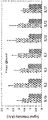
도 11은 형광신호를 이용하여 바이오어세이를 수행한 결과를 나타낸 것이다.
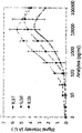
도 12는 항원의 농도에 따른 형광신호의 세기를 나타낸 그래프이다.
도 13은 색상신호를 이용하여 바이오어세이를 수행한 결과를 나타낸 것이다.
도 14는 바이오어세이의 색상신호의 세기를 나타낸 그래프이다.
도 15는 항원의 농도에 따른 색상신호의 세기를 나타낸 그래프이다.
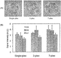
도 16은 색상신호를 이용한 다중 바이오어세이의 결과를 나타낸 것이다.
본 발명의 일 측면에 의하면, (a) 섬유 가닥의 표면에 표적 물질과 특이적으로 반응하는 탐지 물질을 도포하여 반응성 섬유 가닥을 얻는 단계; (b) 서로 다른 종류의 상기 탐지 물질들로 도포된 상기 반응성 섬유 가닥들을 모아 구조화하되, 상기 구조화 과정에서 매트릭스 물질을 이용해 상기 반응성 섬유 가닥들을 고정함으로써 섬유 묶음을 형성하는 단계; 및 (c) 상기 섬유 묶음을 길이 방향에 대해 단면이 보이도록 썰어내어 상기 매트릭스 물질 내에 상기 섬유 묶음의 조각이 고정된 절단물을 얻는 단계를 포함하는 바이오어세이 플랫폼의 제조방법이 제공된다.
먼저 도 1의 S1 단계에서 섬유 가닥의 표면에 표적 물질과 특이적으로 반응하는 탐지 물질을 도포하여 반응성 섬유 가닥들을 얻는다. 상기 섬유 가닥은 다양한 고분자 섬유 (면섬유와 같은 셀룰로오스 기반 섬유, 콜라겐과 같은 천연 고분자 섬유, 나일론과 같은 합성 고분자 섬유 등), 탄소 섬유 등 일 수 있으나 이에 한정되지 않으며 가늘고 긴 필라멘트(filament) 또는 실(thread) 형태를 가지며 탐지 물질을 흡착하거나 수용할 수 있는 물질을 모두 포함할 수 있다. 바람직하게는 값이 매우 싸고 쉽게 구할 수 있으며 섬유 가닥의 표면에 다양한 화학 작용기를 올려 기능화 하기가 용이한 면섬유를 이용할 수 있다.
본 발명을 구현하는데 있어서 사용되는 섬유 가닥의 길이나 두께 등은 한정되지 않는다. 섬유 가닥의 길이가 길수록 섬유 묶음의 길이가 길어지고 섬유 묶음을 절단하였을 때 나오는 바이오어세이 플랫폼의 개수가 증가하기 때문에, 생산하고자 하는 플랫폼의 개수에 따라 섬유 가닥의 길이를 조절할 수 있다. 섬유 가닥의 두께가 두꺼울수록 본 발명의 섬유 묶음의 단면의 크기가 커지기 때문에 최종적인 바이오어세이 플랫폼의 크기를 결정하게 되는데, 이는 본 발명의 성능에 거의 영향을 미치지 않으므로 필요에 따라 임의로 조절할 수 있다. 즉, 본 발명에 사용되는 섬유 가닥의 물리적인 특징은 본 발명의 성능에 큰 영향이 없으므로 매우 다양한 굵기 및 길이의 섬유가 사용 가능하다.
상기 표적물질과 특이적으로 반응하는 탐지 물질은 항체, 효소, 질병 표지물질 등과 같은 단백질 기반 생분자 또는 핵산 기반 생분자일 수 있으며, 상기 섬유 가닥에 부착되어 표적 물질과 반응할 수 있는 물질을 모두 포함할 수 있다.
본 발명의 일 구현예에 있어서, 상기 탐지 물질의 도포는 상기 섬유 가닥에 상기 탐지 물질을 물리적 흡착시키는 방식으로 수행할 수 있다. 상기 섬유 가닥을 특정한 탐지 물질이 포함된 용액에 담갔다 꺼내어 건조하는 방법으로 섬유 가닥에 탐지 물질을 간단히 도입할 수 있다.
본 발명의 다른 구현예에 있어서, 상기 탐지 물질의 도포는 상기 섬유 가닥에 상기 탐지 물질을 화학적으로 결합시키는 방식으로 수행할 수 있다. 상기 섬유 가닥의 표면에 화학 물질을 처리하여 작용기를 형성한 후 작용기를 활성화시키고 탐지 물질이 포함된 용액에 상기 섬유 가닥을 적셔 말리는 과정을 통하여 상기 섬유 가닥에 탐지 물질을 화학적으로 연결시킬 수 있다. 도 2는 화학처리를 통하여 섬유 가닥의 표면을 변형시키는 일 실시예를 나타낸 것이다. 도 2를 참조하면, 셀룰로오스 기반 섬유 가닥의 표면의 수산기를 이용하여 상기 섬유 가닥의 표면에 카르복실화된 아민기를 형성시킬 수 있다. 이를 통하여 상기 섬유 가닥의 표면에 상기 탐지 물질을 높은 효율로 고정시킬 수 있으며, 상기 탐지 물질과 표적 물질과의 반응성을 높여 표적 물질에 대한 검출 신호의 세기를 강화하고 검출 한계를 낮출 수 있다.
도 3은 본 발명의 반응성 섬유 가닥을 이용하여 인터루킨4(IL4)에 대한 바이오어세이를 수행한 일 실시예를 나타낸 것이다. 도 3의 왼쪽 그래프는 섬유 가닥에 탐지 물질을 화학적으로 연결한 경우(1)와 흡착시킨 경우(2)의 바이오어세이 신호의 세기를 비교한 것으로, 그래프의 보라색 막대는 탐지 물질을 화학적으로 연결한 경우(1)와 단순히 흡착시킨 경우(2)의 형광신호의 세기(Fluorescence Intensity)이며 연두색 막대는 탐지 물질을 처리하지 않은 대조군(control)의 형광신호 세기이다. 도 3의 오른쪽 사진을 참조하면 탐지 물질을 흡착시킨 섬유 가닥(2)의 단일 가닥에서 형광신호를 검출할 수 있으며, 탐지 물질을 섬유 가닥에 화학적으로 연결한 경우(1)에는 더 강한 신호를 검출할 수 있고 형광신호가 섬유 전체에 고르게 나타나는 것을 확인할 수 있다.
다음으로, 도 1의 S2 단계에서 서로 다른 종류의 상기 탐지 물질들로 도포된 상기 반응성 섬유 가닥들을 모아 구조화하되, 상기 구조화 과정에서 매트릭스 물질을 이용해 상기 반응성 섬유 가닥들을 고정함으로써 섬유 묶음을 형성한다.
하나의 섬유 가닥 전체에 동일한 탐지 물질을 처리 할 수 있으며, 복수개의 섬유 가닥마다 서로 동일하거나 상이한 종류의 탐지 물질을 처리할 수 있다. 복수개의 섬유 가닥 각각을 다른 종류의 탐지 물질이 포함된 용액으로 적셔 각각의 섬유 가닥에 여러 가지 탐지 물질을 다양하게 결합시킬 수 있다. 상기 탐지 물질이 결합된 기능화된 섬유 가닥을 바이오어세이에 이용하는 경우 상기 반응성 섬유 가닥에 고정된 여러 가지 탐지 물질과 각각의 탐지 물질에 특이적으로 작용하는 표적 물질이 물리적으로 결합하거나 화학적으로 반응하여 특정 표적 물질을 검출할 수 있다.
상기 탐지 물질들로 도포된 상기 반응성 섬유 가닥들을 모아 구조화하여 섬유 묶음을 만들 수 있다. 다중 어세이를 위한 확장성을 위해 서로 다른 처리가 된 여러 가닥의 섬유 가닥들을 모아 묶음(bundle) 형태로 한데 모여 있게 할 수 있다. 도 4는 복수개의 섬유 가닥들을 다양한 방법으로 하우징 하거나 피복 처리하여 구조화하는 구현예들을 나타낸 것이다. 도 4를 참조하면, 섬유 가닥들을 얇은 시트(sheet) 형태로 만든 후 둥글게 말거나(도 4의 (A)) 시트를 접어서 쌓아 올리는 방법(도 4의 (B)), 혹은 국수를 뽑아내듯 물질을 채워 섬유 가닥들의 묶음을 한 번에 고정하는 방법(도 4의 (C)) 등 다양한 방법으로 섬유 가닥들의 묶음을 형성 할 수 있다. 섬유 가닥들의 구조화 방법은 이에 한정되지 않으며, 바이오어세이시 복수개의 섬유 가닥 간에 오염이 발생하지 않도록 서로 공간적으로 분리할 수 있고 섬유 가닥의 위치정보를 이용하여 각 섬유 가닥에 고정된 탐지 물질의 종류를 구별할 수 있는 방법이면 어떤 방법도 사용될 수 있다.
도 5는 테이프를 이용하여 섬유 가닥들을 구조화하여 섬유 묶음을 만들고 바이오어세이를 위한 플랫폼을 제작하는 일 구현예를 나타낸 것이다. 도 5를 참조하면, 테이프와 같은 접착력이 있는 필름 위에 다양한 물질로 기능화된 섬유 가닥들을 정렬하고 그 위에 한 번 더 테이프를 붙여 섬유 가닥들을 얇은 시트(sheet)의 형태로 만든 다음 시트를 둥글게 말아 섬유 가닥들의 묶음 형태를 만들 수 있다. 섬유 가닥들을 구조화하기 위한 매트릭스 물질로 테이프 이외에 상기 섬유 가닥들의 위치를 고정하고 서로 공간적으로 분리할 수 있는 어떤 물질도 이용 가능하다. 상기 구조화된 섬유 묶음을 얇게 슬라이스화하여 각각의 조각을 시료에 담가 섬유 가닥들의 변화를 관찰할 수 있다.
도 6은 파라핀을 이용한 피복처리를 통하여 섬유 묶음을 만드는 일 구현예를 나타낸 것이다. 도 6을 참조하면, 복수개의 섬유 가닥들을 한데 모아 액체 상태의 파라핀에 담갔다가 꺼낸 다음 파라핀을 냉각하여 고형화하는 과정을 통하여 섬유 묶음을 형성 할 수 있다. 이 경우에는 상기 섬유 가닥들이 서로 공간적으로 완벽히 고립되어 추후 바이오어세이시 하나로 묶여있는 각 검출 영역 간에 상호 오염이 발생하지 않는다. 상기 섬유 가닥들을 피복처리하기 위한 매트릭스 물질로 파라핀 이외에 액체였다가 특정 조건에서 서서히 고형화되는 경화성 고분자 수지 등의 물질을 이용할 수 있다. 이때, 상기 매트릭스 물질은 화학적으로 안정되어 있고, 생분자를 파괴할 정도의 독성이 없으며, 액체와 고체 상태일 때의 온도와 액체에서 고체로의 상변화시 온도가 단백질이나 핵산과 같은 생분자를 파괴하지 않는 온도 범위 내에 있을 수 있다. 본 발명의 다른 구현예에 있어서, 섬유 가닥들을 테이프로 구조화한 후 파라핀으로 고정하여 섬유 묶음을 만들 수 있다.
본 발명의 일 구현예에 있어서, 상기 구조화 과정은 상기 반응성 섬유 가닥에 도포된 상기 탐지 물질의 정보를 구별하기 위해 코딩 섬유 가닥을 배치하는 단계를 더 포함할 수 있다. 구조화 과정에서 반응성 섬유 가닥과 코딩 섬유 가닥을 함께 묶어 상기 반응성 섬유 가닥에 부착된 탐지 물질의 종류를 상기 코딩 섬유 가닥의 코딩정보를 통하여 구별할 수 있다.
본 발명의 일 구현예에 있어서, 상기 구조화 과정은 상기 반응성 섬유 가닥에 대하여 대응하는 상기 코딩 섬유 가닥의 색상, 개수, 배열 순서, 섬유 가닥의 크기 또는 이들의 조합을 조절함으로써 수행될 수 있다. 도 7은 섬유 묶음의 다양한 코딩 구현예를 보여주는 것으로, 흰색 섬유는 반응성 섬유 가닥을 나타내고 붉은색, 푸른색, 노란색 섬유는 코딩 섬유 가닥을 나타낸다. 도 7을 참조하면, (A)와 같이 여러 가닥의 반응성 섬유 가닥들과 다양한 색상의 코딩 섬유 가닥을 일정한 규칙으로 배열한 후 섬유 묶음으로 구조화할 수 있으며, (B)와 같이 코딩 섬유 가닥의 크기를 달리하여 코딩할 수 있다. 도 7의 (C)와 같이 한 가닥의 반응성 섬유 가닥과 한 가닥의 코딩 섬유 가닥을 커플링하여 섬유 묶음을 구조화할 수 있다. 반응성 섬유 가닥과 코딩 섬유 가닥을 테이프로 고정한 다음 전체 섬유 가닥들을 파라핀으로 피복처리하는 방법으로 섬유 묶음을 형성할 수 있다.
도 8은 본 발명의 바이오어세이 플랫폼의 제조방법의 일 구현예를 도안화한 것으로, 반응성 섬유 가닥을 회색으로, 코딩 섬유 가닥을 여러 가지 색상으로 나타내었다. 도 8을 참조하면, 다양한 탐지 물질이 결합되어 있는 반응성 섬유 가닥들과 다양한 색상을 가진 코딩 섬유 가닥들을 일대일로 짝지은 다음 전체 섬유 가닥들을 한데 모아 구조화할 수 있다. 이 경우에는 코딩 섬유 가닥의 색상을 이용하여 인접하는 반응성 섬유 가닥에 존재하는 탐지 물질의 종류를 식별할 수 있다. 상술한 코딩방법을 이용하면 반응성 섬유 가닥과 코딩 섬유 가닥의 색상, 크기, 개수, 순서 등을 변화시켜 다양한 신호를 코딩할 수 있다.
본 발명의 일 구현예에 있어서, 상기 구조화 과정은 자성 물질이 도입된 자기제어용 섬유 가닥들을 배치하는 단계를 더 포함할 수 있다.
상기 자기제어용 섬유 가닥은 섬유 가닥의 표면에 자기 입자를 화학적 또는 물리적으로 부착하는 방법을 이용해 제작할 수 있다. 화학적인 방법은 섬유 가닥에 화학적 작용기를 부착하고 자기 입자의 표면에 화학적 작용기 부착이 가능한 물질을 코팅한 다음 두 물질을 화학적으로 붙이는 방식으로 수행할 수 있다. 물리적인 방법은 나노 크기의 입자의 물리적 흡착을 이용하여 단순히 섬유 가닥을 자기 입자가 퍼져 있는 액체에 담근 후 꺼내서 말리는 방식으로 수행할 수 있다. 상기 모든 방법에 있어서 초상자성 입자를 포함하여 다양한 크기와 종류의 자기 입자가 활용 가능하고, 섬유에 부착하는 자기 입자의 양은 화학적 부착, 혹은 물리적 부착 과정에서 액체 내에 담겨 있는 자기 입자의 농도를 조절하여 제어할 수 있다. 상기 반응성 섬유가닥들과 상기 자성을 가지는 자기제어용 섬유 가닥들을 함께 구조화함으로써 바이오어세이시 상기 섬유 묶음의 절편을 자기장 또는 자석을 이용하여 조절할 수 있다. 자기 입자가 많이 부착된 섬유 가닥은 외부 자기장에 더 쉽게 반응하고 자기 입자가 적게 부착된 섬유 가닥은 외부 자기장에 덜 민감하게 반응하므로, 외부 자기장을 이용하여 본 발명의 바이오어세이 플랫폼을 조정할 수 있다.
본 발명의 다른 구현예에 있어서, 상기 매트릭스 물질은 자성 물질을 포함할 수 있다. 섬유 묶음을 구조화하는 과정에서 사용하는 액체 상태의 파라핀에 자기 입자를 섞은 후 함께 고체화시켜 상기 섬유 묶음을 구조화할 수 있다. 별도의 자기제어용 섬유 가닥들을 없이 상기 자성물질을 포함하는 매트릭스 물질을 이용하여 구조화함으로써 바이오어세이시 상기 섬유 묶음의 절편을 자기장 또는 자석을 이용하여 조절할 수 있다. 상기 매트릭스 물질과 혼합하는 상기 자기 입자의 농도를 조절함으로써 외부 자기장에 대한 상기 섬유 묶음의 반응성을 조절할 수 있다.
마지막으로, 도 1의 S3 단계에서 상기 섬유 묶음을 길이 방향에 대해 단면이 보이도록 썰어내어 상기 매트릭스 물질 내에 상기 섬유 가닥들의 조각들이 고정된 절단물을 얻는다. 도 5 및 도 6을 재참조하면, 칼이나 기타 도구를 활용하여 상기 섬유 묶음을 구성하는 섬유 가닥들의 단면이 보이도록 일정한 두께를 가진 단면 조각들로 잘라낼 수 있다. 형성된 절단물의 단면을 보면 각 기능을 수행하는 섬유 가닥들의 단면이 보이며, 각각의 절단물이 다중 바이오어세이를 위한 플랫폼이 될 수 있다.
본 발명의 다른 측면에 의하면, (a) 섬유 가닥의 표면에 표적 물질과 특이적으로 반응하는 탐지 물질을 도포하여 반응성 섬유 가닥을 얻는 단계; (b) 서로 다른 종류의 상기 탐지 물질들로 도포된 상기 반응성 섬유 가닥들을 모아 구조화하되, 상기 구조화 과정에서 매트릭스 물질을 이용해 상기 반응성 섬유 가닥들을 고정함으로써 섬유 묶음을 형성하는 단계; (c) 상기 섬유 묶음을 길이 방향에 대해 단면이 보이도록 썰어내어 상기 매트릭스 물질 내에 상기 섬유 가닥들의 조각들이 고정된 절단물을 얻는 단계; 및 (d) 상기 절단물을 바이오어세이용 플랫폼으로 이용하는 단계를 포함하는 바이오어세이 방법이 제공된다.
상기 절편화된 섬유 묶음 조각에 바이오어세이를 진행하여 섬유 묶음 절편의 단면에 표지 되는 검출 신호를 통해 어세이 결과를 평가할 수 있다. 상기 플랫폼에 표적 물질이 포함된 시료를 처리하면 상기 표적 물질과 특이적으로 반응하는 반응성 섬유 가닥의 조각에 신호가 표지될 수 있다. 다중 바이오어세이에서 서로 다른 종류의 검출 신호를 구별하는 방법은 탐지 물질이 도포된 섬유 가닥의 위치 정보 활용, 서로 다른 표지 물질의 사용, 반응 위치에 코드 삽입 등이 있으며, 이에 한정되지 않는다.
본 발명의 일 구현예에 있어서, 반응성 섬유 가닥들을 일정한 규칙으로 정렬하여 섬유 묶음으로 구조화하는 경우 섬유 묶음 내 각 반응성 섬유 가닥들의 위치가 고정되므로 그 위치 정보를 이용하여 도포된 탐지 물질의 종류를 구별할 수 있다. 본 발명의 다른 구현예에 있어서, 바이오어세이의 검출 대상이 되는 표적 물질에 방사성 화합물, 형광물질, 발광물질, 발색물질, 효소, 금속 등의 표지물질을 연결하여 검출 신호를 구별할 수 있다. 본 발명의 또 다른 구현예에 있어서, 각 섬유 가닥 조각에 처리된 탐지 물질의 종류를 알기 쉽게 하기 위해 코딩 정보를 포함하고 있는 섬유도 함께 구조화하여 코딩 섬유 가닥을 이용해 검출 신호가 내포하고 있는 정보를 구별하게 할 수 있다.
상기 플랫폼을 이용하여 바이오어세이로서 면역검정(Immunoassay), 효소검정(Enzymatic assay) 등을 수행하여 다양한 물질의 검출에 활용할 수 있다. 상술한 섬유 가닥들의 구조화 방법을 통하여 서로 고립된 섬유 가닥 조각들이 모여있는 플랫폼의 부피를 최소한으로 낮추었으므로, 전체 어세이 과정에서 사용하는 시료의 양을 줄일 수 있다. 또한, 검출하려는 표적 물질의 종류를 늘리기 위해서는 플랫폼을 제작할 때 구조화 과정에서 함께 묶는 반응성 섬유 가닥의 개수만 증가시키면 되기 때문에 시스템의 확장성이 매우 크다.
다중 바이오어세이에서 서로 다른 종류의 검출 신호를 구별하기 위하여 섬유 묶음 조각의 단면을 육안 또는 현미경으로 확인하거나 카메라 등으로 촬영한 후 사진에서 신호가 표지된 부분과 코딩 정보를 읽어 어세이 결과를 분석할 수 있다. 본 발명의 일 구현예에 있어서, 상기 검출 신호는 반응성 섬유 가닥에서 형광 신호 혹은 색상 변화를 관찰하여 반응이 일어났음을 판단할 수 있다.
어세이 결과의 분석 시스템은 플랫폼에서 사용하는 검출 신호의 종류에 따라 달라진다. 형광 신호를 사용할 경우, 투명한 기판 위에 놓고 형광 현미경이나 리더기를 통해 신호를 읽고 정보를 추출할 수 있다. 본 발명의 일 구현예에 있어서, 상기 섬유 묶음의 플랫폼에 표적 물질이 포함된 시료를 처리한 후 표적 물질과 특이적으로 반응하는 탐지 물질을 처리하고 상기 탐지 물질에 형광표지를 연결함으로써 형광신호를 발생시킬 수 있다. 이에 의하여 표적 물질과 반응한 섬유 가닥에서 형광신호가 나타나게 되며 그 반응성 섬유 가닥에 해당하는 코딩 정보를 읽어 어세이 결과를 분석할 수 있다. 본 발명의 바이오어세이 플랫폼에 표적 물질을 포함한 시료를 처리하면 상기 표적 물질과 반응성 섬유 가닥에 고정된 특정 탐지 물질이 특이적으로 반응하게 된다. 여기에 상기 표적 물질과 특이적으로 반응하는 탐지 물질을 처리한 다음 상기 탐지 물질에 형광표지를 연결하면, 결과적으로 표적 물질이 연결된 반응성 섬유 가닥에서만 반응신호를 발생시킬 수 있다.
색상 신호를 사용할 경우 일반 카메라 혹은 휴대폰 카메라를 통해 적절한 조도 아래서 단면을 찍고 신호의 세기를 추출할 수 있다. 본 발명의 일 구현예에 있어서, 상기 섬유 묶음의 플랫폼에 표적 물질이 포함된 시료를 처리한 후 표적 물질과 특이적으로 반응하는 탐지 물질을 처리하고 상기 탐지 물질에 기질의 색상을 변화시킬 수 있는 효소를 연결함으로써 색상신호를 발생시킬 수 있다. 이에 의하여 표적 물질과 반응한 섬유가닥에서만 색상신호가 나타나게 되며 그 반응섬유가닥에 해당하는 코딩정보를 읽어 어세이 결과를 분석할 수 있다.
본 발명의 바이오어세이 플랫폼에서 표적 물질의 검출을 위한 신호를 발생시키는 방법은 일반적 바이오어세이에서 사용하는 어떤 방법을 사용할 수 있다. 본 발명의 플랫폼을 이용한 바이오어세이에서는 본 플랫폼만을 위한 별도의 시스템 또는 분석장비 없이 신호의 검출과 분석이 가능하므로 고가의 분석 장비가 필요하지 않아 코딩 과정 역시 플랫폼과 실험 분석 비용을 낮추는데 기여를 한다.
본 발명의 또 다른 측면에 의하면, 매트릭스; 및 상기 매트릭스에 고정되어 있는 복수의 반응성 섬유 가닥들의 조각들로 구성된 섬유 묶음 절편을 포함하되, 상기 복수의 반응성 섬유 가닥들의 조각들이 각각 서로 다른 탐지 물질들로 도포되어 있는 바이오어세이 플랫폼이 제공된다. 도 9는 본 발명의 일 구현예에 따른 섬유 묶음(100) 및 바이오어세이 플랫폼(200)을 도안화한 것이다. 도 9를 참조하면, 본 발명의 바이오어세이 플랫폼(200)은 각각 다른 탐지 물질이 흡수된 여러 가닥의 반응성 섬유 가닥(111)들을 한데 모아 매트릭스 물질(120)로 구조화하여 만든 섬유 묶음(100)의 절단물의 형태일 수 있다.
본 발명의 다중 바이오어세이 플랫폼(200)은 표적 물질의 감지를 위한 다양한 탐지 물질을 처리하여 기능화된 반응성 섬유 가닥들의 조각(211)들을 포함할 수 있다. 본 발명에서 기능화란 섬유 가닥에 특정 탐지 물질을 고정시켜 표적 물질과 반응할 수 있는 기능을 가지도록 하는 것을 뜻한다. 바이오어세이에서 검출할 물질의 종류를 늘리기 위해서는 간단히 반응성 섬유 가닥들의 조각들의 종류와 개수를 늘리는 과정을 통하여 플랫폼을 확장할 수 있다.
본 발명의 다중 바이오어세이 플랫폼(200)은 상기 기능화된 반응성 섬유 가닥들의 조각(211)들이 매트릭스 물질(120)에 의하여 구조화된 형태일 수 있다. 상기 구조화는 상기 바이오어세이 플랫폼(200)을 구성하는 각 반응성 섬유 가닥들의 조각(211)들이 상호 오염이 발생하지 않도록 서로 공간적으로 분리하여 배치하는 것일 수 있다. 상기 매트릭스 물질은 접착성 필름, 파라핀, 고분자 수지 및 이들의 조합으로 이루어진 군 중에서 선택되는 어느 하나의 물질을 포함할 수 있다.
본 발명의 다중 바이오어세이 플랫폼(200)은 각각의 반응성 섬유 가닥들의 조각들에 결합된 상기 탐지 물질들의 정보에 관한 코딩 정보를 포함하고 있는 코딩 섬유 가닥들의 조각(212)들을 더 포함할 수 있다. 본 발명의 일 구현예에 있어서, 상기 코딩 정보는 형광 신호 또는 색상 신호일 수 있다. 본 발명의 일 구현예에 있어서, 상기 코딩 섬유 가닥은 색상이 있는 섬유 가닥일 수 있다. 도 9에서는 반응성 섬유 가닥들의 조각(211)들을 흰색으로, 코딩 섬유 가닥들의 조각(212)들을 여러 가지 색깔로 나타내었다.
본 발명의 다중 바이오어세이 플랫폼(200)은 자성 물질을 포함하고 있는 자기제어용 섬유 가닥들의 조각들(213)을 더 포함할 수 있다. 도 10은 본 발명의 다른 구현예에 따른 섬유 묶음(100) 및 바이오어세이 플랫폼(200)을 도안화한 것이다. 도 10에서는 다양한 탐지 물질이 처리된 반응성 섬유 가닥들의 조각(211)들을 다양한 색깔로 나타내었으며, 자기제어용 섬유 가닥들의 조각들(213)을 초록색으로 나타내었다. 본 발명의 일 구현예에 있어서, 여러 가지 탐지 물질이 결합된 반응성 섬유 가닥들의 조각들(211)이 플랫폼의 가운데에 위치하고, 그 주위에 조절층(control layer)으로서 자기제어용 섬유 가닥들의 조각들(213)이 둘러쌀 수 있다.
본 발명의 다중 바이오어세이 플랫폼(200)은 대조군(control) 섬유 가닥을 더 포함할 수 있다. 대조군 섬유 가닥은 바이오어세이시 반응이 일어난 반응성 섬유 가닥의 조각과 반응이 일어나지 않은 반응성 섬유 가닥의 조각 간의 대조군 신호로 이용될 수 있다.
이하 실시예를 통하여 본 발명을 구체적으로 설명한다.
실시예 1 : 섬유의 표면처리 및 반응물질 도포
먼저 무명실을 (3-아미노프로필) 트리에톡시실레인((3-Aminopropyl) triethoxysilane, 99%)가 5% 들어있는 에탄올에 넣고 25℃에서 2시간 동안 반응시킨 후 110℃에서 어닐링(annealing) 시키며 말렸다. 이 실을 아민-프리 디메틸포름아미드(amine-free dimethylformamide)에 안하이드라이드(anhydride, 6% w/w) 와 트리에틸아민(triethylamine, 0.84% v/v)를 희석시킨 용액에 넣고 25℃에서 2시간동안 반응시키고 세척하였다. 이 실을 MES 버퍼에 5% N-히드록시숙신이미드(N-Hydroxysuccinimide)와 5% 에틸(디메틸아미노-프로필) 카르보디이미드(ethyl(dimethylamino-propyl) carbodiimide)를 희석시킨 용액에 넣고 25℃에서 20분 동안 반응시켜 작용기를 활성화시켰다. 마지막으로 표적 물질인 3가지 인터루킨(IL4, IL5 및 IL7)에 대응하는 탐지 물질로서 포획항체(capture antibody)를 MES 버퍼에 각각 희석한 용액에 상기 활성화된 여러 가닥의 실을 각각 적시고 하룻밤동안 말려 상기 인터루킨과 반응하는 포획 항체가 화학적으로 결합된 3가지의 반응성 섬유 가닥들을 완성하였다.
실시예 2 : 섬유의 구조화 및 절단물 형성
투명한 스카치 테이프 위에 상기 3가지 포획항체로 생분자 처리된 반응성 섬유 가닥들을 순서대로 나열하고 그 위에 스카치 테이프를 한 겹 더 붙인 후 둥글게 말아 섬유 묶음을 만들었다. 상기 섬유 묶음을 전자레인지(microwave oven)로 녹인 파라핀에 담갔다 꺼낸 후 상온에서 굳히는 과정을 통하여 피복 처리 하였다. 이렇게 만들어진 긴 섬유 묶음을 면도칼을 이용하여 일정한 두께를 가진 얇은 슬라이스들로 썰어 냈다. 단면을 보면 각 기능을 수행하는 반응성 섬유가닥들의 조각들이 보이며, 각 슬라이스가 다중 바이오어세이를 위한 플랫폼이 된다.
실시예 3-1 : 형광신호를 이용한 바이오어세이 수행
상기 실시예 1에서 제작한 반응성 섬유 가닥 및 상기 실시예 2에서 제작한 바이오어세이용 플랫폼에 대하여 아래의 표 1과 같이 바이오어세이를 수행하였다.
표 1
| 어세이 공정 | 반응 물질 | 반응농도 | 항체당 반응량 | 시간 | 온도 |
| 포획항체 고정 | IL4, IL5, IL7의 포획항체 | 10㎍/ml | 15㎕ | 2시간 | 25℃ |
| 항원 선별 탐지 | IL4, IL5, IL7 | 10ng/ml | 30㎕ | 2시간 | 4℃ |
| 탐지항체 결합 | IL4, IL5, IL7의 탐지항체 | 10㎍/ml | 30㎕ | 1시간 | 25℃ |
| 형광 물질 결합 | 형광 물질이 표지된 효소(Enzyme) | 5㎍/ml | 30㎕ | 30분 | 25℃ |
도 11은 상기 플랫폼을 이용하여 인터루킨4, 인터루킨5, 인터루킨7 각각에 대한 바이오어세이를 수행한 결과를 나태낸 것이다. 다양한 포획항체로 각각 처리된 반응성 섬유 가닥들의 조각들로 이루어진 섬유 묶음 절편에 대하여 항원으로서 인터루킨4, 인터루킨5 및 인터루킨7을 각각 처리하였을 때, 각 항원에 대응하는 포획항체로 기능화된 섬유가닥만이 형광을 나타내었으며, 형광신호는 섬유 묶음 절편 내의 반응성 섬유 가닥의 조각의 위치정보를 이용하여 검출이 가능하였다.
도 12는 항원의 농도(Ag Concentration)에 따른 형광신호의 세기(Fluorescence Intensity)를 나타낸 것으로, 검출 한계는 10 pg/ml이며, 100pg/ml ~ 100㎍/ml의 범위에서 인터루킨의 농도에 따라 신호의 세기가 일정하게 커지므로 이 범위 내에서 단백질의 정량이 가능함을 확인하였다.
실시예 3-2 : 색상신호를 이용한 바이오어세이 수행
7가지 인터루킨(IL1 beta, IL2, IL5, IL7, IL10, IL12 및 IL17)에 대응하는 포획항체를 MES 버퍼에 각각 희석한 용액을 만든 다음, 상기 실시예 1에서 표면처리된 섬유 가닥들을 상기 용액에 각각 적시고 하룻밤동안 말려 상기 인터루킨과 반응하는 포획 항체가 화학적으로 결합된 7가지의 기능성 반응성 섬유 가닥들을 완성하였다. 그런 다음 상기 7가지 포획항체로 생분자 처리된 반응성 섬유가닥들 및 대조군 신호를 위한 섬유와 8가지 색상을 띄는 코딩을 위한 섬유를 한 쌍으로 테이핑하였다(IL1베타 반응성 섬유와 빨간색 코딩 섬유, IL2 반응성 섬유와 주황색 코딩 섬유, IL5 반응성 섬유와 노란색 코딩 섬유, IL7 반응성 섬유와 초록색 코딩 섬유, IL10 반응성 섬유와 파란색 코딩 섬유, IL12 반응성 섬유와 갈색 코딩 섬유, IL17 반응성 섬유와 보라색 코딩 섬유 및 대조군 섬유와 검정색 코딩 섬유). 실시예 2에서 섬유물질을 구조화한 과정과 동일하게 상기 8가지 섬유물질 쌍을 스카치 테이프를 이용하여 둥글게 말아 섬유 묶음을 만들고 파라핀으로 피복 처리한 다음 면도칼을 이용하여 얇은 조각들로 썰어 내어 바이오어세이를 위한 플랫폼을 제작하였다(도 13의 (A)참조).
상기 플랫폼에 대하여 아래의 표 2와 같이 바이오어세이를 수행하였다.
표 2
| 어세이 공정 | 반응 물질 | 반응농도 | 항체당 반응량 | 시간 | 온도 |
| 포획항체 고정 | IL1 beta, IL2, IL5, IL7, IL10, IL12, IL17의 포획항체 | 10㎍/ml | 15㎕ | 2시간 | 25℃ |
| 항원 선별 탐지 | IL1 beta, IL2, IL5, IL7, IL10, IL12, IL17 | 10ng/ml | 30㎕ | 2시간 | 4℃ |
| 탐지항체 결합 | IL1 beta, IL2, IL5, IL7, IL10, IL12, IL17의 탐지항체 | 10㎍/ml | 30㎕ | 1시간 | 25℃ |
| 효소 결합 | 효소(Enzyme) | 5㎍/ml | 30㎕ | 30분 | 25℃ |
| 신호 증폭 | 기질(Substrate) | - | 15㎕ | 8분 | 25℃ |
상기 플랫폼을 항원으로서 7가지 인터루킨을 각각을 포함하는 액체에서 반응시킨 후 세척(washing)하고 특정 인터루킨을 감지하기 위한 탐지항체 용액에서 반응시켜 탐지항체를 붙였다. 끝으로 탐지항체가 붙었는지 알 수 있는 효소 용액에서 반응시켜 효소를 붙이고 최종적으로 효소에서 반응하는 기질 용액에서 반응을 시켜 섬유의 색상이 흰색에서 파란색으로 변화하는지를 확인하였다. 색상 신호가 나타난 조각의 단면을 육안 또는 현미경으로 관찰하거나 일반 카메라 등으로 촬영한 후 사진에서 반응섬유의 색상이 변한 부분과 코딩섬유의 정보를 읽어 어세이 결과를 분석하였다. 도 13은 상기 7가지 인터루킨 각각에 대한 어세이 전(A)과 어세이 후(B)의 플랫폼의 단면을 카메라로 촬영한 사진이다. 도 13을 참조하면, 코팅 섬유 가닥의 색상을 통하여 각 신호를 판별할 수 있었으며, 각각의 인터루킨이 고정되어 있는 반응성 섬유 가닥의 조각에서만 파란색의 색상신호가 나타나는 것을 확인하였다. 도 14는 상기 바이오어세이의 신호의 세기(Signal Intensity)를 나타낸 그래프로, 대조군 섬유(Control, 연두색 막대)와 비교하였을 때 표적 인터루킨에 대응하는 섬유(Target, 보라색 막대)에서 높은 신호의 세기를 나타내는 것을 확인하였다.
도 15는 세 가지 인터루킨(IL1 beta, IL10 및 IL17)의 색상신호의 세기(Signal Intensity)를 인터루킨(Analytes)의 농도별로 나타낸 것으로, 검출 한계는 10 pg/ml이며, 100pg/ml ~ 10㎍/ml의 범위에서 인터루킨의 농도에 따라 신호의 세기가 일정하게 커지므로 이 범위 내에서 단백질의 정량이 가능함을 확인하였다.
실시예 3-3 : 색상신호를 이용한 다중 바이오어세이 수행
상기 실시예 3-2에서 제작한 플랫폼에 대하여 다중 바이오어세이(multiplex bioassay)를 수행하였다. 상기 표 2와 같은 조건에서 어세이를 수행하되, 항원 고정 단계에서 여러 가지 항원을 동시에 처리하였다. 도 16의 (A)는 각각 항원으로서 인터루킨 17만을 처리한 바이오어세이(Single-plex), 3가지 인터루킨(IL1 beta, IL10 및 IL17)을 동시에 처리한 바이오어세이(3-plex) 및 7가지 인터루킨(IL1 beta, IL2, IL5, IL7, IL10, IL12 및 IL17)을 모두 처리한 바이오어세이(7-plex)의 결과를 카메라로 촬영한 사진이며, 도 16의 (B)는 각 어세이의 신호세기(Signal Intensity)를 나타낸 그래프이다. 여러 가지 표적 물질을 동시에 처리한 경우에도 각각의 표적 물질을 검출할 수 있으며, 다중 어세이시에도 검출신호의 세기가 충분히 나타나는 것을 확인하였다.
Claims (17)
- (a) 섬유 가닥의 표면에 표적 물질과 특이적으로 반응하는 탐지 물질을 도포하여 반응성 섬유 가닥을 얻는 단계;(b) 서로 다른 종류의 상기 탐지 물질들로 도포된 상기 반응성 섬유 가닥들을 모아 구조화하되, 상기 구조화 과정에서 매트릭스 물질을 이용해 상기 반응성 섬유 가닥들을 고정함으로써 섬유 묶음을 형성하는 단계; 및(c) 상기 섬유 묶음을 길이 방향에 대해 단면이 보이도록 썰어내어 상기 매트릭스 물질 내에 상기 섬유 가닥들의 조각들이 고정된 절단물을 얻는 단계를 포함하는 바이오어세이 플랫폼의 제조방법.
- 제1 항에 있어서,상기 탐지 물질의 도포는 상기 섬유 가닥에 상기 탐지 물질을 물리적 흡착 또는 화학적 결합시키는 방식으로 수행하는 바이오어세이 플랫폼의 제조방법.
- 제1항에 있어서,상기 구조화 과정은 상기 반응성 섬유 가닥에 도포된 상기 탐지 물질의 정보를 구별하기 위해 코딩 섬유 가닥을 배치하는 단계를 더 포함하는 바이오어세이 플랫폼의 제조방법.
- 제3항에 있어서,상기 구조화 과정은 상기 반응성 섬유 가닥에 대하여 대응하는 상기 코딩 섬유 가닥의 색상, 개수, 배열 순서, 섬유 가닥의 크기 또는 이들의 조합을 조절함으로써 수행되는 바이오어세이 플랫폼의 제조방법.
- 제1항에 있어서,상기 구조화 과정은 자성 물질이 도입된 자기제어용 섬유 가닥들을 배치하는 단계를 더 포함하는 바이오어세이 플랫폼의 제조방법.
- 제1항에 있어서,상기 섬유 가닥은 셀룰로오스 기반 섬유인 바이오어세이 플랫폼의 제조방법.
- 제1항에 있어서,상기 구조화 과정은 상기 반응성 섬유 가닥들을 서로 공간적으로 분리하여 상기 섬유 묶음을 만드는 것인 바이오어세이 플랫폼의 제조방법.
- (a) 섬유 가닥의 표면에 표적 물질과 특이적으로 반응하는 탐지 물질을 도포하여 반응성 섬유 가닥을 얻는 단계;(b) 서로 다른 종류의 상기 탐지 물질들로 도포된 상기 반응성 섬유 가닥들을 모아 구조화하되, 상기 구조화 과정에서 매트릭스 물질을 이용해 상기 반응성 섬유 가닥들을 고정함으로써 섬유 묶음을 형성하는 단계;(c) 상기 섬유 묶음을 길이 방향에 대해 단면이 보이도록 썰어내어 상기 매트릭스 물질 내에 상기 섬유 가닥들의 조각들이 고정된 절단물을 얻는 단계; 및(d) 상기 절단물을 바이오어세이용 플랫폼으로 이용하는 단계를 포함하는 바이오어세이 방법.
- 제8항에 있어서,상기 섬유 묶음의 절단물의 단면에 표지되는 검출 신호를 통해 어세이 결과를 평가하는 바이오어세이 방법.
- 제9항에 있어서,상기 검출 신호는 상기 섬유 묶음 내 상기 반응성 섬유 가닥의 위치, 상기 표적 물질에 연결된 표지 물질 및 상기 섬유 묶음 내에서 상기 반응성 섬유 가닥과 함께 구조화된 코딩 섬유 가닥으로 이루어진 군으로부터 선택되는 1종 이상의 정보로부터 얻어지는 것인 바이오어세이 방법.
- 매트릭스; 및상기 매트릭스에 고정되어 있는 복수의 반응성 섬유 가닥들의 조각들로 구성된 섬유 묶음 절편을 포함하되,상기 복수의 반응성 섬유 가닥들의 조각들이 각각 서로 다른 탐지 물질들로 도포되어 있는 바이오어세이 플랫폼.
- 제11항에 있어서,상기 매트릭스 물질은 접착성 필름, 파라핀, 고분자 수지 및 이들의 조합으로 이루어진 군 중에서 선택되는 어느 하나의 물질로 된 것인 바이오어세이 플랫폼.
- 제11항에 있어서,상기 섬유 묶음 절편은 상기 탐지 물질들의 정보에 관한 코딩 정보를 포함하고 있는 코딩 섬유 가닥들의 조각들을 더 포함하는 바이오어세이 플랫폼.
- 제13항에 있어서,상기 코딩 정보는 형광 신호 또는 색상 신호인 바이오어세이 플랫폼.
- 제11항에 있어서,상기 섬유 묶음 절편을 구성하는 각 반응성 섬유 가닥들의 조각들이 상호 오염이 발생하지 않도록 서로 공간적으로 분리되어 배치된 바이오어세이 플랫폼.
- 제11항에 있어서,상기 섬유 묶음 절편은 자성 물질을 포함하고 있는 자기제어용 섬유 가닥들의 조각들을 더 포함하는 바이오어세이 플랫폼.
- 제11항에 있어서,상기 매트릭스는 자성 물질을 포함하는 것인 바이오어세이 플랫폼.
Priority Applications (1)
| Application Number | Priority Date | Filing Date | Title |
|---|---|---|---|
| US15/030,617 US20160266106A1 (en) | 2013-10-28 | 2014-10-28 | Multiplex bioassay platform using cut fiber bundle |
Applications Claiming Priority (2)
| Application Number | Priority Date | Filing Date | Title |
|---|---|---|---|
| KR20130128740 | 2013-10-28 | ||
| KR10-2013-0128740 | 2013-10-28 |
Publications (1)
| Publication Number | Publication Date |
|---|---|
| WO2015065008A1 true WO2015065008A1 (ko) | 2015-05-07 |
Family
ID=53004532
Family Applications (1)
| Application Number | Title | Priority Date | Filing Date |
|---|---|---|---|
| PCT/KR2014/010177 Ceased WO2015065008A1 (ko) | 2013-10-28 | 2014-10-28 | 섬유묶음 절단물을 이용한 다중 바이오어세이 플랫폼 |
Country Status (3)
| Country | Link |
|---|---|
| US (1) | US20160266106A1 (ko) |
| KR (1) | KR101652177B1 (ko) |
| WO (1) | WO2015065008A1 (ko) |
Citations (5)
| Publication number | Priority date | Publication date | Assignee | Title |
|---|---|---|---|---|
| US20010031504A1 (en) * | 2000-04-14 | 2001-10-18 | Lg Electronics Inc. | Biochip and method for fabricating the same |
| JP2004532408A (ja) * | 2001-04-05 | 2004-10-21 | ゲゼルシャフト フュア バイオテクノロギッシェフォーシュング エムベーハー(ゲーベーエフ) | プローブ分子からなる平坦な検査用アレイの同一のコピーを多数製造する方法 |
| WO2012067402A2 (ko) * | 2010-11-16 | 2012-05-24 | 한국생명공학연구원 | 자가-결합 활성을 갖는 적색 형광 단백질 단편, 이의 제조방법 및 이를 이용한 단백질 상호작용의 분석 방법 |
| KR20130006145A (ko) * | 2011-07-08 | 2013-01-16 | 고려대학교 산학협력단 | 앱타머가 고정화된 나노섬유 복합체 및 이를 이용한 단백질 분리/정제의 용도 |
| WO2013105774A1 (ko) * | 2012-01-09 | 2013-07-18 | 사회복지법인 삼성생명공익재단 | 절단 가능한 프로브를 이용한 c-Met 유전자 검출 방법 |
Family Cites Families (2)
| Publication number | Priority date | Publication date | Assignee | Title |
|---|---|---|---|---|
| US6129896A (en) * | 1998-12-17 | 2000-10-10 | Drawn Optical Components, Inc. | Biosensor chip and manufacturing method |
| US6908737B2 (en) * | 1999-04-15 | 2005-06-21 | Vitra Bioscience, Inc. | Systems and methods of conducting multiplexed experiments |
-
2014
- 2014-10-28 WO PCT/KR2014/010177 patent/WO2015065008A1/ko not_active Ceased
- 2014-10-28 US US15/030,617 patent/US20160266106A1/en not_active Abandoned
- 2014-10-28 KR KR1020140147313A patent/KR101652177B1/ko active Active
Patent Citations (5)
| Publication number | Priority date | Publication date | Assignee | Title |
|---|---|---|---|---|
| US20010031504A1 (en) * | 2000-04-14 | 2001-10-18 | Lg Electronics Inc. | Biochip and method for fabricating the same |
| JP2004532408A (ja) * | 2001-04-05 | 2004-10-21 | ゲゼルシャフト フュア バイオテクノロギッシェフォーシュング エムベーハー(ゲーベーエフ) | プローブ分子からなる平坦な検査用アレイの同一のコピーを多数製造する方法 |
| WO2012067402A2 (ko) * | 2010-11-16 | 2012-05-24 | 한국생명공학연구원 | 자가-결합 활성을 갖는 적색 형광 단백질 단편, 이의 제조방법 및 이를 이용한 단백질 상호작용의 분석 방법 |
| KR20130006145A (ko) * | 2011-07-08 | 2013-01-16 | 고려대학교 산학협력단 | 앱타머가 고정화된 나노섬유 복합체 및 이를 이용한 단백질 분리/정제의 용도 |
| WO2013105774A1 (ko) * | 2012-01-09 | 2013-07-18 | 사회복지법인 삼성생명공익재단 | 절단 가능한 프로브를 이용한 c-Met 유전자 검출 방법 |
Also Published As
| Publication number | Publication date |
|---|---|
| KR101652177B1 (ko) | 2016-08-31 |
| US20160266106A1 (en) | 2016-09-15 |
| KR20150050424A (ko) | 2015-05-11 |
Similar Documents
| Publication | Publication Date | Title |
|---|---|---|
| Lucas et al. | Lab-on-a-chip immunoassay for multiple antibodies using microsphere light scattering and quantum dot emission | |
| DE60040603D1 (de) | Verfahren zur analyse einer mehrzahl von proben verschiedenen ursprungs auf einen analyten | |
| KR101266244B1 (ko) | 다중-기능 및 구성가능한 분석 시스템 | |
| CA2353868A1 (en) | Composite arrays utilizing microspheres | |
| US7241629B2 (en) | Detectable labels, methods of manufacture and use | |
| CN113631912B (zh) | 基于珠粒的样品分析 | |
| JP2004537712A (ja) | 多重細胞分析システム | |
| WO2000063419B1 (en) | Combinatorial chemical library supports having indicia at coding positions and methods of use | |
| CA2374735A1 (en) | Encoding and decoding of array sensors utilizing nanocrystals | |
| JP2003004738A (ja) | マイクロアレイおよびその製造方法 | |
| WO2011065747A2 (ko) | 나노입자를 이용한 미생물의 고속 검출방법 | |
| WO2013051889A2 (ko) | 한 번의 시료 주입으로 순차적인 반응 조건의 변화가 가능한 멤브레인 센서 | |
| CA2424176A1 (en) | Multiplexed cell analysis system | |
| WO2014137069A1 (ko) | 다중 진단용 병렬식 라인형 바이오칩 | |
| WO2015065008A1 (ko) | 섬유묶음 절단물을 이용한 다중 바이오어세이 플랫폼 | |
| DE10054382A1 (de) | Verfahren und Testkit zum Nachweis von Analyten in einer Probe | |
| WO2007032653A1 (en) | A new label-free high throughput screening method by using sers spectroscopic encoded bead and dielectrophoresis | |
| CN110618273B (zh) | 一种同时检测多种金黄色葡萄球菌肠毒素的荧光编码微球试纸条的制备方法 | |
| WO2013147388A1 (ko) | Cmos 이미지 센서의 픽셀 분석을 이용한 고감도 바이오센서 | |
| WO2016182402A1 (ko) | 복수개의 금속 나노 태그를 이용한 복수개의 타겟의 동시 분석 방법 | |
| Kim et al. | Fiber composite slices for multiplexed immunoassays | |
| WO2017065585A1 (ko) | 생체 시료의 선별적 처리방법 | |
| CN108693347A (zh) | 多通道免疫层析用标记垫及制作方法和检测试剂卡 | |
| WO2021075881A2 (ko) | 하이드로젤 입자 기반 표적물질 비색 검출법 | |
| WO2018199465A1 (ko) | 재귀반사 현상을 이용한 분자 비콘 기반의 광학 유전자 바이오센서 및 이를 이용한 핵산 분자의 정량 분석 방법 |
Legal Events
| Date | Code | Title | Description |
|---|---|---|---|
| 121 | Ep: the epo has been informed by wipo that ep was designated in this application |
Ref document number: 14857664 Country of ref document: EP Kind code of ref document: A1 |
|
| WWE | Wipo information: entry into national phase |
Ref document number: 15030617 Country of ref document: US |
|
| NENP | Non-entry into the national phase |
Ref country code: DE |
|
| 122 | Ep: pct application non-entry in european phase |
Ref document number: 14857664 Country of ref document: EP Kind code of ref document: A1 |