WO2015064190A1 - 冷蔵庫 - Google Patents
冷蔵庫 Download PDFInfo
- Publication number
- WO2015064190A1 WO2015064190A1 PCT/JP2014/072216 JP2014072216W WO2015064190A1 WO 2015064190 A1 WO2015064190 A1 WO 2015064190A1 JP 2014072216 W JP2014072216 W JP 2014072216W WO 2015064190 A1 WO2015064190 A1 WO 2015064190A1
- Authority
- WO
- WIPO (PCT)
- Prior art keywords
- water supply
- refrigerator
- supply tank
- water
- opening
- Prior art date
- Legal status (The legal status is an assumption and is not a legal conclusion. Google has not performed a legal analysis and makes no representation as to the accuracy of the status listed.)
- Ceased
Links
Images






Classifications
-
- F—MECHANICAL ENGINEERING; LIGHTING; HEATING; WEAPONS; BLASTING
- F25—REFRIGERATION OR COOLING; COMBINED HEATING AND REFRIGERATION SYSTEMS; HEAT PUMP SYSTEMS; MANUFACTURE OR STORAGE OF ICE; LIQUEFACTION SOLIDIFICATION OF GASES
- F25D—REFRIGERATORS; COLD ROOMS; ICE-BOXES; COOLING OR FREEZING APPARATUS NOT OTHERWISE PROVIDED FOR
- F25D23/00—General constructional features
- F25D23/12—Arrangements of compartments additional to cooling compartments; Combinations of refrigerators with other equipment, e.g. stove
-
- F—MECHANICAL ENGINEERING; LIGHTING; HEATING; WEAPONS; BLASTING
- F25—REFRIGERATION OR COOLING; COMBINED HEATING AND REFRIGERATION SYSTEMS; HEAT PUMP SYSTEMS; MANUFACTURE OR STORAGE OF ICE; LIQUEFACTION SOLIDIFICATION OF GASES
- F25C—PRODUCING, WORKING OR HANDLING ICE
- F25C1/00—Producing ice
- F25C1/22—Construction of moulds; Filling devices for moulds
-
- F—MECHANICAL ENGINEERING; LIGHTING; HEATING; WEAPONS; BLASTING
- F25—REFRIGERATION OR COOLING; COMBINED HEATING AND REFRIGERATION SYSTEMS; HEAT PUMP SYSTEMS; MANUFACTURE OR STORAGE OF ICE; LIQUEFACTION SOLIDIFICATION OF GASES
- F25C—PRODUCING, WORKING OR HANDLING ICE
- F25C2400/00—Auxiliary features or devices for producing, working or handling ice
- F25C2400/10—Refrigerator units
-
- F—MECHANICAL ENGINEERING; LIGHTING; HEATING; WEAPONS; BLASTING
- F25—REFRIGERATION OR COOLING; COMBINED HEATING AND REFRIGERATION SYSTEMS; HEAT PUMP SYSTEMS; MANUFACTURE OR STORAGE OF ICE; LIQUEFACTION SOLIDIFICATION OF GASES
- F25D—REFRIGERATORS; COLD ROOMS; ICE-BOXES; COOLING OR FREEZING APPARATUS NOT OTHERWISE PROVIDED FOR
- F25D2323/00—General constructional features not provided for in other groups of this subclass
- F25D2323/122—General constructional features not provided for in other groups of this subclass the refrigerator is characterised by a water tank for the water/ice dispenser
Definitions
- the present invention relates to a refrigerator for making ice by supplying water to an ice tray from a water supply tank.
- Patent Document 1 A conventional refrigerator is disclosed in Patent Document 1.
- This refrigerator has a refrigerator compartment at the top and a freezer compartment at the bottom.
- the refrigerator compartment and the freezer compartment are partitioned by a heat insulating wall.
- An ice making room is arranged in the freezer compartment.
- a water supply tank is arranged on the heat insulating wall in the refrigerator compartment, and an ice tray is arranged in the ice making room.
- the water in the water supply tank is guided to the ice tray by a water supply pipe. Ice is made by freezing the water supplied to the ice tray.
- a tank heater that heats the water supply tank is provided.
- the tank heater is embedded in the heat insulating wall below the water supply tank. Thereby, freezing of the water in a water supply tank is prevented.
- a pipe heater is provided in the water supply pipe in order to prevent residual water in the water supply pipe from freezing and causing poor water supply.
- the tank heater is provided in the storage chamber, extra cooling energy is required, which is contrary to energy saving. In addition, there is a problem that costs increase. Further, since the tank heater is embedded in the heat insulating wall, it is difficult to check and replace the tank heater, and there is a problem that the maintainability of the refrigerator is lowered.
- the present invention aims to provide a refrigerator capable of improving energy saving capability and maintainability and reducing costs.
- the refrigerator of the present invention comprises a refrigerator compartment for storing stored items in a refrigerator, a freezer compartment for storing stored items in a frozen state adjacent to the lower portion of the refrigerator compartment via an insulating wall, and the insulating walls.
- a refrigerator comprising a water supply tank placed on top and an ice making tray disposed in the freezer compartment and supplying ice from the water supply tank to the ice making tray, water storage in which the water supply tank is stored by water supply And a projecting portion projecting downward from the bottom wall of the water storage portion, and the projecting portion forms an air passage through which cool air flows between the bottom wall of the water storage portion and the heat insulating wall.
- the present invention provides the refrigerator having the above-described configuration, wherein the protruding portion includes a grounding portion that is grounded on the heat insulating wall, and an opening for allowing cool air to flow into and out of the ventilation path between the adjacent grounding portions. It is formed.
- the refrigerator may include a return port through which cold air flows out on the back surface of the refrigerator compartment, and the opening facing the front of the water supply tank and the opening facing the rear.
- the present invention has the opening facing the side of the water supply tank, and the opening area of the opening facing backward is larger than the opening area of the opening facing forward. It is large.
- the return port is disposed in the vicinity of the back surface of the water supply tank.
- cold air is generated between the bottom wall of the water storage unit and the heat insulating wall by the protruding portion protruding from the bottom wall of the water storage unit of the water supply tank placed on the heat insulating wall between the refrigerator compartment and the freezing chamber. Since the circulation passage is formed, water in the water supply tank can be prevented from freezing. Accordingly, a tank heater is not required, and energy saving capability and maintainability of the refrigerator can be improved and costs can be reduced.
- the front view which shows the refrigerator of 1st Embodiment of this invention The front view which shows the cold air
- Side surface sectional drawing of the water supply tank of the refrigerator of 1st Embodiment of this invention The bottom view of the water supply tank of the refrigerator of 1st Embodiment of this invention
- CC sectional view of FIG. The front view of the lower part of the water supply tank of the refrigerator of 4th Embodiment of this invention.
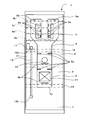
- FIG. 2 and FIG. 3 are a front view showing the refrigerator 1 of the first embodiment, a front view showing a cold air passage, and a cross-sectional view taken along line AA of FIG.
- the refrigerator 1 has a heat insulating box 3 filled with a foam heat insulating material 13 such as polyurethane foam between an outer box 14 and an inner box 15.
- the heat insulation box 3 is provided with a refrigerator compartment 4 in the upper part, and freezer compartments 21 and 5 are juxtaposed on the left and right below the refrigerator compartment 4.
- a freezer compartment 6 is arranged below the freezer compartments 21 and 5, and a vegetable compartment 7 is arranged below the freezer compartment 6.
- the refrigerator compartment 4 and the freezer compartments 21 and 5 are partitioned by a heat insulating wall 18, and the freezer compartment 6 and the vegetable compartment 7 are partitioned by a heat insulating wall 19.
- the heat insulating walls 18 and 19 are filled with a heat insulating material such as polystyrene foam.
- the refrigerator compartment 4 stores stored items in a refrigerated state and is opened and closed by heat insulating doors 4L and 4R that are pivotally supported at the left and right ends, respectively.
- shelves 4b, 4c, 4d, and 4e are arranged in order from the top.
- a chilled chamber 70 described later is provided on the right side when viewed from the front, and a water supply unit 17 is provided on the left side.
- the freezer compartments 21, 5 and 6 communicate with each other inside and store the stored items in a frozen state.
- the freezing chamber 21 constitutes an ice making chamber as will be described in detail later.
- the front surface of the freezer compartment 21 is opened and closed by a heat insulating door 21a pivotally supported at the left end, and the front surface of the freezer compartment 5 is opened and closed by a heat insulating door 5a pivotally supported at the right end.
- the front surface of the freezer compartment 6 is opened and closed by a drawer-type heat insulating door 6a.
- the vegetable room 7 refrigerates stored items at a refrigeration temperature higher than that of the refrigerator room 4, and stores vegetables and fruits.
- the front of the vegetable compartment 7 is opened and closed by a drawer-type heat insulating door 7a.
- a machine room 30 is provided on the back side of the vegetable room 7.
- the machine room 30 is provided with a compressor 31 that operates the refrigeration cycle.
- the freezer compartment 21 is adjacent to the lower part of the refrigerator compartment 4 through the heat insulating wall 18, and an ice tray 22 and an ice storage container 24 are arranged.
- the ice tray 22 makes ice
- the ice storage container 24 stores the ice made by the ice tray 22. Accordingly, the freezer compartment 21 constitutes an ice making chamber that performs ice making.
- the water supply unit 17 provided in the lower part of the refrigerator compartment 4 includes a water supply tank 50, a water supply pipe 45, and a water supply pump 46.
- the water supply tank 50 is detachably provided and stores city water or the like.
- the water supply pipe 45 is led out from the water supply tank 50 and extends through the heat insulating wall 18 to the ice tray 22.
- the water supply pump 46 is arranged on the path of the water supply pipe 45, and water is supplied from the water supply tank 50 to the ice tray 22 by driving the water supply pump 46.
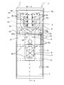
- a cold air passage 9 through which cold air flows is provided behind the freezer compartments 5 and 6.
- the cool air passage 9 is opened with a discharge port 9a and a return port 9b facing the freezer compartments 5 and 6.
- a cooler 11 serving as a low temperature part of the refrigeration cycle is disposed in the cold air passage 9.
- a blower fan 10 is disposed above the cooler 11.
- a cold air passage 8 communicating with the cold air passage 9 via a damper 28 is provided behind the refrigerator compartment 4. Discharge ports 8 a and 8 b are opened in the cold air passage 8. A plurality of discharge ports 8 a are provided in the refrigerator compartment 4, and the discharge ports 8 b are provided in the chilled chamber 70.
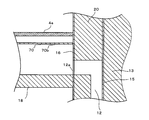
- the chilled chamber 70 is isolated from the refrigerator compartment 4 by the side wall 70a and the upper wall 70b.
- the discharge port 8 b is provided on the back surface of the chilled chamber 70. Since the discharge port 8b is provided upstream of the cool air passage 8 near the cooler 11, the inside of the chilled chamber 70 is maintained at a lower temperature than the surroundings.
- a gap 70 c is provided between the side wall 70 a and the heat insulating wall 18.
- FIG. 4 shows a BB cross-sectional view of FIG.
- a back panel 16 is provided on the back of the refrigerator compartment 4.
- a heat insulating material 20 that forms the cool air passage 8 is provided on the back side of the back panel 16.
- the return port 12 a is arranged on the right side of the cold air passage 9 and is connected to the communication passage 12 that communicates the chilled chamber 70 and the vegetable compartment 7.
- a discharge port 12 b (see FIG. 2) is arranged at the downstream end of the communication path 12 so as to face the vegetable compartment 7.
- the water supply tank 50 is formed of a transparent resin molded product, and is detachably provided on the heat insulating wall 18.
- the water supply tank 50 has a water storage part 51 that opens on the upper surface and a lid part 58 that opens and closes the upper surface of the water storage part 51.
- the lid 58 is removed and the water is stored in the water storage 51.
- a pipe connection portion 58a connected to the water supply pipe 45 (see FIG. 3) is provided at the rear portion of the lid portion 58.
- a water supply pipe heater (not shown) is attached to the water supply pipe 45 for the purpose of preventing freezing of residual water after water supply. Further, the water supply pipe 45 is embedded in the heat insulating wall 18 with a predetermined inclination angle in order to prevent water splashing at the time of water supply.
- the water supply pipe 45 can be embedded in the heat insulating wall 18 at a predetermined angle in the vertical direction by providing a horizontal angle without passing directly under the water supply tank 50.
- An immersion pipe 58b that extends downward from the pipe connection portion 58a and is immersed in the water storage of the water storage portion 51 is provided on the inner surface side of the lid portion 58. By driving the water supply pump 46, the water in the water storage section 51 is pumped up through the immersion pipe 58b.
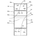
- the water reservoir 51 has projecting portions 52, 53, 54, 55, 56 that project downward from the bottom wall 51a.
- the protrusions 52 and 53 are formed so as to extend from the side wall of the water reservoir 51 and extend in the front-rear direction, and are provided facing each other.
- the protrusion 52 has grounding portions 52a and 52b and an opening 52c.
- the grounding part 52 a is provided at the front part of the protruding part 52, and the grounding part 52 b is provided at the rear part of the protruding part 52.
- the grounding parts 52 a and 52 b are grounded to the heat insulating wall 18.
- the opening 52c is formed in a substantially U shape, and is provided between the adjacent grounding portions 52a and 52b (the central portion of the protruding portion 52).
- the protruding portion 53 has grounding portions 53a and 53b and an opening 53c.
- the grounding part 53 a is provided at the front part of the protruding part 53, and the grounding part 53 b is provided at the rear part of the protruding part 53.
- the grounding portions 53 a and 53 b are grounded to the heat insulating wall 18.
- the opening 53c is formed in a substantially U shape, and is provided between the adjacent grounding portions 53a and 53b (the central portion of the protruding portion 53).
- the protrusions 54, 55, 56 extend in the left-right direction and are connected to the protrusions 52, 53.
- the protrusions 54, 55, and 56 are arranged in parallel on the bottom wall 51 a of the water reservoir 51 in order from the front.
- the protruding portion 54 includes grounding portions 54a and 54b and an opening 54c.
- the grounding part 54 a is provided on one side of the protruding part 54, and the grounding part 54 b is provided on the other side of the protruding part 54.
- the grounding portions 54 a and 54 b are grounded to the heat insulating wall 18.
- the opening 54c is formed in a U-shape and is provided between the adjacent grounding portions 54a and 54b (the central portion of the protruding portion 54).
- the protruding portion 55 has grounding portions 55a and 55b and an opening 55c.
- the grounding portion 55 a is provided on one side of the protruding portion 55, and the grounding portion 55 b is provided on the other side of the protruding portion 55.
- the grounding portions 55 a and 55 b are grounded to the heat insulating wall 18.
- the opening 55c is formed in a U-shape, and is provided between adjacent grounding portions 55a and 55b (the central portion of the protruding portion 55).
- the protruding portion 56 is formed to extend from the rear wall of the water storage portion 51, and has grounding portions 56a and 56b and an opening portion 56c.
- the grounding portion 56 a is provided on one side of the protruding portion 56, and the grounding portion 56 b is provided on the other side of the protruding portion 56.
- the grounding portions 56 a and 56 b are grounded to the heat insulating wall 18.
- the opening 56c is formed in a U-shape and is provided between the adjacent grounding portions 56a and 56b (the central portion of the protruding portion 56).
- a ventilation path 59 is formed between the bottom wall 51a of the water storage section 51 and the heat insulating wall 18 as shown by the arrow D2 through the openings 52c, 53c, 54c, 55c, and 56c.
- the opening 54c is opened facing the front of the water supply tank 50, the opening 56c is opened facing the rear, and the opening 55c is arranged between the openings 54c and 56c. For this reason, the cool air flowing backward in the refrigerator compartment 4 toward the return port 12 a provided on the back panel 16 is easy to flow in the ventilation path 59.
- the openings 52c and 53c are opened facing the side of the water supply tank 50. For this reason, it is more desirable to make the opening area of the opening part 56c facing rearward larger than the opening area of the opening part 54c facing frontward. Thereby, in addition to the opening part 54c, the cold air which flowed into the ventilation path 59 from the opening parts 52c and 53c flows out smoothly from the opening part 56c. Therefore, it is possible to increase the amount of cool air flowing through the ventilation path 59.
- the cold air generated by heat exchange between the air flowing through the cold air passage 9 and the cooler 11 by driving the compressor 31 and the blower fan 10 is discharged from the discharge port 9a into the freezer compartments 5, 6, and 21. Discharged.
- the cold air discharged from the discharge port 9a flows through the freezer compartments 5, 6, 21 and returns to the cooler 11 through the return port 9b. Thereby, cooling in the freezer compartments 5, 6, and 21 is performed.
- the cold air flowing out from the return port 12a flows through the communication passage 12 and is discharged to the vegetable compartment 7 through the discharge port 12b.
- the cold air that has circulated through the vegetable compartment 7 returns to the cooler 11 through the return port 9c. Thereby, the inside of the vegetable compartment 7 is cooled.
- the water storage portion is provided by the protruding portions 52, 53, 54, 55, and 56 that protrude from the bottom wall 51 a of the water storage portion 51 placed on the heat insulating wall 18 between the refrigerator compartment 4 and the freezer compartment 5. Since the ventilation path 59 through which the cold air flows is formed between the bottom wall 51a of the 51 and the heat insulating wall 18, the water in the water supply tank 50 can be prevented from freezing. Therefore, a tank heater is not required, and the maintainability of the refrigerator 1 can be improved and the cost can be reduced.
- the protrusions 52, 53, 54, 55, and 56 have a plurality of grounding portions 52a, 52b, 53a, 53b, 54a, 54b, 55a, 55b, 56a, and 56b that are grounded to the heat insulating wall 18, and the ventilation path Openings 52 c, 53 c, 54 c, 55 c, and 56 c through which cool air flows into and out of 59 are formed between adjacent grounding portions. Thereby, the ventilation path 59 through which cool air flows can be easily realized.
- the return port 12a from which the cold air flows out is provided on the back surface of the refrigerator compartment 4 and has the opening portion 54c facing the front side of the water supply tank 50 and the opening portion 56c facing the rear side, the cool air toward the back return port 12a.
- the water in the water supply tank 50 can be more reliably prevented from being frozen.
- openings 52c and 53c facing the side of the water supply tank 50 are provided, and the opening area of the opening 56c facing the rear of the water tank 50 is larger than the opening area of the opening 54c facing the front. For this reason, the amount of cool air flowing through the ventilation path 59 is increased, and freezing of water in the water supply tank 50 can be more reliably prevented.
- FIG. 9 has shown the front view which shows the cold air
- the same reference numerals are given to the same parts as those of the first embodiment shown in FIGS.
- the communication passage 12 is arranged on the left side of the cold air passage 9 with respect to the first embodiment. Other parts are the same as those in the first embodiment.
- the communication path 12 is connected to a return port 12a that opens to the rear of the water supply unit 17 disposed at the lower left portion of the refrigerator compartment 4, and has a discharge port 12b provided at the left portion of the vegetable chamber 7 at the downstream end.
- the return port 12 a is disposed in the vicinity of the back surface of the water supply tank 50. For this reason, the cool air flowing backward in the refrigerator compartment 4 toward the return port 12 a flows in the ventilation path 59.
- the same effect as that of the first embodiment can be obtained. Moreover, since the return port 12a is arranged in the vicinity of the back surface of the water supply tank 50, it becomes easier for cold air to circulate in the ventilation path 59 than in the first embodiment. Therefore, a lot of cold air can circulate more reliably.
- FIGS. 10 and 11 are a front view showing a cold air passage of the refrigerator 1 of the third embodiment, and a cross-sectional view taken along the line CC of FIG.
- the same reference numerals are given to the same parts as those of the first embodiment shown in FIGS.
- This embodiment is different from the first embodiment in that a communication path 40 is provided.
- Other parts are the same as those in the first embodiment.
- a return port 40 a is opened in the rear panel 16 behind the water supply tank 50.
- the return port 40 a is connected to the communication path 40.
- the communication path 40 is formed in the back panel 16 so as to extend in the left-right direction, and is connected upstream with the return port 12a.
- the cold air circulates backward in the refrigerator compartment 4 toward the return port 40 a and circulates in the ventilation path 59.
- circulated to the communicating path 40 via the return port 40a distribute
- a part of the water supply pipe heater may be extended forward in the heat insulating wall 18 and disposed upstream of the return port 40a (in front of the water supply tank 50). Thereby, the temperature of the cold air flowing into the return port 40a can be raised by the heat transfer of the water supply pipe heater.
- the same effect as that of the first embodiment can be obtained. Moreover, since the return port 40a is arranged on the back surface of the water supply tank 50, it becomes easier for cold air to flow in the ventilation path 59 than in the first embodiment. Therefore, a lot of cold air can circulate more reliably.
- FIG. 12 has shown the water supply tank 50 front view and bottom view of the refrigerator 1 of 3rd Embodiment.
- the same reference numerals are given to the same parts as those of the first embodiment shown in FIGS.
- This embodiment differs in the shape of the protrusion part of the water supply tank 50 with respect to 1st Embodiment. Other parts are the same as those in the first embodiment.
- a water supply tank 50 is provided in the lower part of the refrigerator compartment 4.
- the bottom wall 51 a of the water storage section 51 of the water supply tank 50 is provided with rectangular protrusions 60 and 61 that protrude downward and are provided at both side ends of the front portion of the water storage section 51.
- rectangular protrusions 62 and 63 are provided on both side ends of the rear portion of the bottom wall 51a.
- the lower surfaces of the protrusions 60, 61, 62, 63 form grounding portions 60 a, 61 a, 62 a, 63 a that are grounded to the heat insulating wall 18.
- An opening 64 is formed between the adjacent grounding part 60a and the grounding part 61a, and an opening 65 is formed between the adjacent grounding part 60a and the grounding part 62a.
- An opening 66 is formed between the adjacent grounding part 61a and the grounding part 63a, and an opening 67 is formed between the adjacent grounding part 62a and the grounding part 63a.
- the ventilation path 59 through which cool air flows between the bottom wall 51a of the water storage section 51 and the heat insulating wall 18 is formed by the protrusions 60, 61, 62, and 63. For this reason, cold air is generated by driving the compressor 31 and the blower fan 10, and the cold air discharged from the discharge port 8a is circulated through the ventilation path 59 as indicated by an arrow D3 to freeze the water in the water supply tank 50. To prevent.
- the same effect as that of the first embodiment can be obtained.
- the shape of the protrusions 60, 61, 62, and 63 is not limited to a rectangular shape, and the number is not limited to four.
- the present invention can be used for a refrigerator for making ice by supplying water to an ice tray from a water supply tank.
Landscapes
- Engineering & Computer Science (AREA)
- Chemical & Material Sciences (AREA)
- Combustion & Propulsion (AREA)
- Physics & Mathematics (AREA)
- Mechanical Engineering (AREA)
- Thermal Sciences (AREA)
- General Engineering & Computer Science (AREA)
- Cold Air Circulating Systems And Constructional Details In Refrigerators (AREA)
- Devices That Are Associated With Refrigeration Equipment (AREA)
Abstract
Description
以下に本発明の実施形態を図面を参照して説明する。図1、図2、図3は第1実施形態の冷蔵庫1を示す正面図、冷気通路を示す正面図、図2のA-A線断面図である。冷蔵庫1は外箱14と内箱15との間にポリウレタンフォーム等の発泡断熱材13を充填した断熱箱体3を有している。
次に、図9は第2実施形態の冷蔵庫1の冷気通路を示す正面図を示している。説明の便宜上、前述の図1~図8に示す第1実施形態と同様の部分には同一の符号を付している。本実施形態は第1実施形態に対して連通路12が冷気通路9の左方に配される。その他の部分は第1実施形態と同様である。
次に、図10、図11は第3実施形態の冷蔵庫1の冷気通路を示す正面図、図10のC-C線断面図である。説明の便宜上、前述の図1~図8に示す第1実施形態と同様の部分には同一の符号を付している。本実施形態は第1実施形態に対して連通路40が設けられている点が異なっている。その他の部分は第1実施形態と同様である。
次に、図12、図13は第3実施形態の冷蔵庫1の給水タンク50正面図、底面図を示している。説明の便宜上、前述の図1~図8に示す第1実施形態と同様の部分には同一の符号を付している。本実施形態は第1実施形態に対して給水タンク50の突出部の形状が異なっている。その他の部分は第1実施形態と同様である。
2 本体部
3 断熱箱体
4 冷蔵室
4b、4c、4d、4e 棚
5 冷凍室
6 冷凍室
6b 断熱扉
7 野菜室
7b 断熱扉
8 冷気通路
8a、8b、9a、12b 吐出口
9 冷気通路
9b、9c 戻り口
10 送風ファン
11 冷却器
12 連通路
12a 戻り口
13 発泡断熱材
14 外箱
15 内箱
16 背面パネル
17 給水部
18、19 断熱壁
20 断熱材
21 冷凍室
22 製氷皿
24 貯氷容器
28 ダンパ
30 機械室
31 圧縮機
40 連通路
40a 戻り口
45 給水パイプ
46 給水ポンプ
50 給水タンク
51 貯水部
51a 底壁
52、53、54、55、56 突出部
52a、52b、53a、53b、54a、54b、55a、55b、56a、56b 接地部
52c、53c、54c、55c、56c 開口部
58 蓋部
58a パイプ接続部
58b 浸漬パイプ
59 通風路
60、61、62、63 突出部
60a、61a、62a、63a 接地部
64、65、66、67 開口部
70 チルド室
70a 側壁
70b 上壁
70c 隙間
Claims (5)
- 貯蔵物を冷蔵保存する冷蔵室と、断熱壁を介して前記冷蔵室の下方に隣接して貯蔵物を冷凍保存する冷凍室と、前記断熱壁上に載置される給水タンクと、前記冷凍室に配される製氷皿とを備え、前記給水タンクから前記製氷皿に給水して製氷を行う冷蔵庫において、
前記給水タンクが給水によって貯水される貯水部と、前記貯水部の底壁から下方に突出する突出部とを有し、前記突出部によって前記貯水部の底壁と前記断熱壁との間に冷気が流通する通風路を形成したことを特徴とする冷蔵庫。 - 前記突出部が前記断熱壁上に接地される接地部を有し、前記通風路に対して冷気を流出入させる開口部を隣接する前記接地部間に形成したことを特徴とする請求項1に記載の冷蔵庫。
- 前記冷蔵室の背面に冷気が流出する戻り口を設け、前記給水タンクの前方に面した前記開口部と後方に面した前記開口部とを有することを特徴とする請求項2に記載の冷蔵庫。
- 前記給水タンクの側方に面した前記開口部を有し、後方に面した前記開口部の開口面積が前方に面した前記開口部の開口面積よりも大きいことを特徴とする請求項3に記載の冷蔵庫。
- 前記戻り口が前記給水タンクの背面近傍に配されることを特徴とする請求項3または請求項4に記載の冷蔵庫。
Priority Applications (1)
| Application Number | Priority Date | Filing Date | Title |
|---|---|---|---|
| CN201480048349.0A CN105556225B (zh) | 2013-11-01 | 2014-08-26 | 冰箱 |
Applications Claiming Priority (2)
| Application Number | Priority Date | Filing Date | Title |
|---|---|---|---|
| JP2013-227981 | 2013-11-01 | ||
| JP2013227981A JP5782091B2 (ja) | 2013-11-01 | 2013-11-01 | 冷蔵庫 |
Publications (1)
| Publication Number | Publication Date |
|---|---|
| WO2015064190A1 true WO2015064190A1 (ja) | 2015-05-07 |
Family
ID=53003805
Family Applications (1)
| Application Number | Title | Priority Date | Filing Date |
|---|---|---|---|
| PCT/JP2014/072216 Ceased WO2015064190A1 (ja) | 2013-11-01 | 2014-08-26 | 冷蔵庫 |
Country Status (3)
| Country | Link |
|---|---|
| JP (1) | JP5782091B2 (ja) |
| CN (1) | CN105556225B (ja) |
| WO (1) | WO2015064190A1 (ja) |
Cited By (1)
| Publication number | Priority date | Publication date | Assignee | Title |
|---|---|---|---|---|
| WO2020136807A1 (ja) * | 2018-12-27 | 2020-07-02 | 三菱電機株式会社 | 冷蔵庫 |
Families Citing this family (1)
| Publication number | Priority date | Publication date | Assignee | Title |
|---|---|---|---|---|
| JP6922725B2 (ja) * | 2017-12-26 | 2021-08-18 | パナソニックIpマネジメント株式会社 | 冷蔵庫 |
Citations (5)
| Publication number | Priority date | Publication date | Assignee | Title |
|---|---|---|---|---|
| JPH1194444A (ja) * | 1997-09-19 | 1999-04-09 | Hitachi Ltd | 冷蔵庫 |
| JP2003075055A (ja) * | 2001-08-28 | 2003-03-12 | Sharp Corp | 冷蔵庫 |
| JP2006064240A (ja) * | 2004-08-25 | 2006-03-09 | Matsushita Electric Ind Co Ltd | 冷蔵庫 |
| JP2007309543A (ja) * | 2006-05-16 | 2007-11-29 | Calsonic Kansei Corp | 車両用温度調整庫 |
| JP2011247550A (ja) * | 2010-05-28 | 2011-12-08 | Mitsubishi Electric Corp | 冷蔵庫 |
Family Cites Families (2)
| Publication number | Priority date | Publication date | Assignee | Title |
|---|---|---|---|---|
| TW330978B (en) * | 1995-03-31 | 1998-05-01 | Mitsubishi Electric Corp | Automatic ice-making device and refrigerator the invention relates to an automatic ice-making device comprising a water supply tank, an ice-making plate and a water-supply pump. |
| JP5478365B2 (ja) * | 2010-05-28 | 2014-04-23 | 三菱電機株式会社 | 冷蔵庫 |
-
2013
- 2013-11-01 JP JP2013227981A patent/JP5782091B2/ja active Active
-
2014
- 2014-08-26 CN CN201480048349.0A patent/CN105556225B/zh active Active
- 2014-08-26 WO PCT/JP2014/072216 patent/WO2015064190A1/ja not_active Ceased
Patent Citations (5)
| Publication number | Priority date | Publication date | Assignee | Title |
|---|---|---|---|---|
| JPH1194444A (ja) * | 1997-09-19 | 1999-04-09 | Hitachi Ltd | 冷蔵庫 |
| JP2003075055A (ja) * | 2001-08-28 | 2003-03-12 | Sharp Corp | 冷蔵庫 |
| JP2006064240A (ja) * | 2004-08-25 | 2006-03-09 | Matsushita Electric Ind Co Ltd | 冷蔵庫 |
| JP2007309543A (ja) * | 2006-05-16 | 2007-11-29 | Calsonic Kansei Corp | 車両用温度調整庫 |
| JP2011247550A (ja) * | 2010-05-28 | 2011-12-08 | Mitsubishi Electric Corp | 冷蔵庫 |
Cited By (1)
| Publication number | Priority date | Publication date | Assignee | Title |
|---|---|---|---|---|
| WO2020136807A1 (ja) * | 2018-12-27 | 2020-07-02 | 三菱電機株式会社 | 冷蔵庫 |
Also Published As
| Publication number | Publication date |
|---|---|
| JP2015087081A (ja) | 2015-05-07 |
| CN105556225B (zh) | 2018-04-27 |
| CN105556225A (zh) | 2016-05-04 |
| JP5782091B2 (ja) | 2015-09-24 |
Similar Documents
| Publication | Publication Date | Title |
|---|---|---|
| US8336330B2 (en) | Refrigerator with icemaker compartment having an improved air flow | |
| CN101910761B (zh) | 冰箱 | |
| KR101519134B1 (ko) | 냉장고 | |
| US9303913B2 (en) | Refrigerator | |
| JP5625561B2 (ja) | 冷蔵庫 | |
| JP6706749B2 (ja) | 冷蔵庫 | |
| JP5782091B2 (ja) | 冷蔵庫 | |
| JP6389075B2 (ja) | 冷蔵庫 | |
| JP6407913B2 (ja) | 冷蔵庫 | |
| JP4864830B2 (ja) | 冷蔵庫 | |
| JP2007187362A (ja) | 冷蔵庫 | |
| JP2011202909A (ja) | 冷蔵庫 | |
| CN101726147B (zh) | 冰箱 | |
| CN102914116B (zh) | 制冷设备 | |
| JP2009121784A (ja) | 冷蔵庫 | |
| KR100389381B1 (ko) | 냉장고의냉기공급구조 | |
| JP6489767B2 (ja) | 冷蔵庫 | |
| JP6709348B2 (ja) | 冷蔵庫 | |
| CN109791014B (zh) | 冰箱 | |
| JP5322870B2 (ja) | 冷蔵庫 | |
| JP2014020684A (ja) | 冷蔵庫 | |
| JP2017194192A (ja) | 冷蔵庫 | |
| JP2004271178A (ja) | 冷蔵庫 | |
| WO2018179468A1 (ja) | 冷蔵庫 | |
| JP2018009788A (ja) | 冷蔵庫 |
Legal Events
| Date | Code | Title | Description |
|---|---|---|---|
| WWE | Wipo information: entry into national phase |
Ref document number: 201480048349.0 Country of ref document: CN |
|
| 121 | Ep: the epo has been informed by wipo that ep was designated in this application |
Ref document number: 14858691 Country of ref document: EP Kind code of ref document: A1 |
|
| WWE | Wipo information: entry into national phase |
Ref document number: IDP00201601397 Country of ref document: ID |
|
| NENP | Non-entry into the national phase |
Ref country code: DE |
|
| 122 | Ep: pct application non-entry in european phase |
Ref document number: 14858691 Country of ref document: EP Kind code of ref document: A1 |