WO2015060388A1 - 鉄骨梁の耐火被覆構造および耐火被覆用貫通スリーブ材 - Google Patents
鉄骨梁の耐火被覆構造および耐火被覆用貫通スリーブ材 Download PDFInfo
- Publication number
- WO2015060388A1 WO2015060388A1 PCT/JP2014/078228 JP2014078228W WO2015060388A1 WO 2015060388 A1 WO2015060388 A1 WO 2015060388A1 JP 2014078228 W JP2014078228 W JP 2014078228W WO 2015060388 A1 WO2015060388 A1 WO 2015060388A1
- Authority
- WO
- WIPO (PCT)
- Prior art keywords
- sleeve material
- steel beam
- web
- hole portion
- refractory
- Prior art date
- Legal status (The legal status is an assumption and is not a legal conclusion. Google has not performed a legal analysis and makes no representation as to the accuracy of the status listed.)
- Ceased
Links
Images



Classifications
-
- F—MECHANICAL ENGINEERING; LIGHTING; HEATING; WEAPONS; BLASTING
- F16—ENGINEERING ELEMENTS AND UNITS; GENERAL MEASURES FOR PRODUCING AND MAINTAINING EFFECTIVE FUNCTIONING OF MACHINES OR INSTALLATIONS; THERMAL INSULATION IN GENERAL
- F16L—PIPES; JOINTS OR FITTINGS FOR PIPES; SUPPORTS FOR PIPES, CABLES OR PROTECTIVE TUBING; MEANS FOR THERMAL INSULATION IN GENERAL
- F16L5/00—Devices for use where pipes, cables or protective tubing pass through walls or partitions
- F16L5/02—Sealing
- F16L5/04—Sealing to form a firebreak device
-
- F—MECHANICAL ENGINEERING; LIGHTING; HEATING; WEAPONS; BLASTING
- F16—ENGINEERING ELEMENTS AND UNITS; GENERAL MEASURES FOR PRODUCING AND MAINTAINING EFFECTIVE FUNCTIONING OF MACHINES OR INSTALLATIONS; THERMAL INSULATION IN GENERAL
- F16L—PIPES; JOINTS OR FITTINGS FOR PIPES; SUPPORTS FOR PIPES, CABLES OR PROTECTIVE TUBING; MEANS FOR THERMAL INSULATION IN GENERAL
- F16L59/00—Thermal insulation in general
- F16L59/12—Arrangements for supporting insulation from the wall or body insulated, e.g. by means of spacers between pipe and heat-insulating material; Arrangements specially adapted for supporting insulated bodies
- F16L59/121—Arrangements for supporting insulation from the wall or body insulated, e.g. by means of spacers between pipe and heat-insulating material; Arrangements specially adapted for supporting insulated bodies for pipes passing through walls or partitions
-
- E—FIXED CONSTRUCTIONS
- E04—BUILDING
- E04B—GENERAL BUILDING CONSTRUCTIONS; WALLS, e.g. PARTITIONS; ROOFS; FLOORS; CEILINGS; INSULATION OR OTHER PROTECTION OF BUILDINGS
- E04B1/00—Constructions in general; Structures which are not restricted either to walls, e.g. partitions, or floors or ceilings or roofs
- E04B1/62—Insulation or other protection; Elements or use of specified material therefor
- E04B1/92—Protection against other undesired influences or dangers
- E04B1/94—Protection against other undesired influences or dangers against fire
- E04B1/941—Building elements specially adapted therefor
- E04B1/943—Building elements specially adapted therefor elongated
- E04B1/944—Building elements specially adapted therefor elongated covered with fire-proofing material
Definitions
- the present invention relates to a fireproof coating technique for a through-hole formed in a steel beam web.
- the fire-resistant covering structure of the steel beam for the through hole formed in the steel beam web is roughly divided into the following two types.
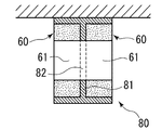
- One is formed with a pair of fireproof covering materials 60 and 60 so as to sandwich the web 81 of the steel beam 80 from both sides, as shown in FIG.
- the other is to insert a refractory material 70 formed in a sleeve shape from one side of the web 81 of the steel beam 80 as shown in FIG. 2 (Patent Document 1, Patent Document 2, etc.).
- the present invention provides a steel beam web that can be constructed from one side of the steel beam web and that is easy to position and does not require a special fixing member.
- the object is to provide a fireproof coating technique for the formed through-holes.
- the present invention provides a steel beam fireproof covering structure for a through hole portion formed in a steel beam web, wherein a through sleeve member made of a fireproof covering material in a cylindrical shape is provided as a through hole portion. And a slit formed in the circumferential direction of the through sleeve material is fitted into the web of the through hole portion.
- the slits formed in the circumferential direction of the through sleeve material may have a wide groove shape (a state where the slit surfaces are separated) or a narrow cut shape (a state where the slit surfaces are in contact).
- the present invention relates to a through sleeve material that penetrates through a through-hole portion formed in a steel beam web, and a slit formed in a circumferential direction of the through-sleeve material made of a cylindrical fireproof coating material has a through-hole portion. Mates to the web.
- the slits formed in the circumferential direction of the through sleeve material may have a wide groove shape (a state where the slit surfaces are separated) or a narrow cut shape (a state where the slit surfaces are in contact).
- the through sleeve material may or may not include an “inner core material” for reinforcement.
- an internal core when an internal core is provided, it is easy to cut the Japanese mackerel in addition to being reinforced (for example, when a through-hole for a through sleeve material is formed in a box-shaped Japanese mackerel).
- the “fireproof covering material” constituting the penetration sleeve material may be carried into the work site in a cylindrical shape in advance, or carried into the work site in a mat shape, that is, in a flat state, and cylindrical at the work site. It may be.
- the through sleeve material can be fixed to the through hole portion without requiring a special fixing member. .
- the stability after penetrating the through sleeve material through the through hole is also obtained.
- FIG. 1A is an explanatory diagram for explaining a conventional technique.
- FIG. 1B is an explanatory diagram for explaining a conventional technique.
- FIG. 2A is an explanatory diagram for explaining a conventional technique.
- FIG. 2B is an explanatory diagram for explaining a conventional technique.
- FIG. 3A is an explanatory diagram showing an embodiment of the present invention.
- FIG. 3B is an explanatory diagram showing an embodiment of the present invention.
- FIG. 3C is an explanatory diagram showing an embodiment of the present invention.
- FIG. 3A, 3B, and 3C are explanatory views showing an embodiment of the present invention.
- a through sleeve material 10 made of a cylindrical fireproof covering material 11 reinforced with an inner core material 19 inside is provided in a through hole portion 82 formed in a web 81 of a steel beam 80.
- slits 12 are formed in the circumferential direction of the through sleeve material 10.
- the slit 12 may have a groove shape with a width as shown in the figure, or may have a notch shape without a width not shown.
- the cylindrical fireproof covering material 11 constituting the through sleeve material 10 is preferably a blanket fireproof covering material mainly composed of rock wool having fire resistance and heat insulation properties, but is not limited thereto.
- the internal core material 19 constituting the through sleeve material 10 is preferably a spiral duct or a bent steel plate, but is not limited thereto.
- the penetration sleeve material 10 as described above is formed on the web 81 of the steel beam 80 that can be constructed from one side of the web 81 of the steel beam 80, is easy to position, and does not require a special fixing member. Further, it is possible to provide a fireproof coating technique for the through hole portion 82.
- the present invention can be widely used as a steel beam fireproof covering structure and a penetration sleeve material for fireproof covering.
Landscapes
- Engineering & Computer Science (AREA)
- General Engineering & Computer Science (AREA)
- Mechanical Engineering (AREA)
- Building Environments (AREA)
Abstract
鉄骨梁のウェブに形成された貫通孔部に、円筒状の耐火被覆材からなる貫通スリーブ材を貫通させる。この時、貫通スリーブ材の円周方向にスリットが形成されている。そして、貫通スリーブ材を貫通孔部に貫通すると、貫通スリーブ材のスリットが貫通孔部のウェブに嵌合する。
Description
本願発明は、鉄骨梁のウェブに形成された貫通孔部に対する耐火被覆技術に関するものである。
鉄骨梁のウェブに形成された貫通孔部に対する鉄骨梁の耐火被覆構造としては、大きく分けて次の2通りのものがある。
1つは、図1に示すように、鉄骨梁80のウェブ81を両側から挟み込むように、一対の耐火被覆材60,60で形成するものである。
もう1つは、図2に示すように、スリーブ状に形成した耐火材70を鉄骨梁80のウェブ81の片側から挿入するものである(特許文献1及び特許文献2等)。
1つは、図1に示すように、鉄骨梁80のウェブ81を両側から挟み込むように、一対の耐火被覆材60,60で形成するものである。
もう1つは、図2に示すように、スリーブ状に形成した耐火材70を鉄骨梁80のウェブ81の片側から挿入するものである(特許文献1及び特許文献2等)。
しかし、上記する従来の技術には、以下のような課題を有している。
(1)前者については、鉄骨梁80のウェブ81の両側からの作業が必要になるとともに、鉄骨梁80の貫通孔部82と異なるサイズの孔61が開いている耐火被覆材60を取り付ける場合、孔中心の位置出しが非常に困難である。
(2)後者については、スリーブ状に形成した耐火材70を鉄骨梁80の貫通孔部82に固定するために、金物など何らかの固定部材が必要になる。なお、上記の特許文献1及び特許文献2は、この固定部材に関する発明である。
(1)前者については、鉄骨梁80のウェブ81の両側からの作業が必要になるとともに、鉄骨梁80の貫通孔部82と異なるサイズの孔61が開いている耐火被覆材60を取り付ける場合、孔中心の位置出しが非常に困難である。
(2)後者については、スリーブ状に形成した耐火材70を鉄骨梁80の貫通孔部82に固定するために、金物など何らかの固定部材が必要になる。なお、上記の特許文献1及び特許文献2は、この固定部材に関する発明である。
そこで、本願発明は、このような課題を解決するために、鉄骨梁のウェブの片側から施工することができて、且つ、位置出しも容易で特別な固定部材も必要のない鉄骨梁のウェブに形成された貫通孔部に対する耐火被覆技術の提供を目的としたものである。
上記目的を達成するために、本発明は、鉄骨梁のウェブに形成された貫通孔部に対する鉄骨梁の耐火被覆構造であって、円筒状にした耐火被覆材からなる貫通スリーブ材を貫通孔部に貫通させるとともに、貫通スリーブ材の円周方向に形成されたスリットが貫通孔部のウェブに嵌合する。
前記貫通スリーブ材の円周方向に形成された前記スリットは、幅のある溝状(スリット面が離れている状態)又は幅のない切り込み状(スリット面が接している状態)としてもよい。
本発明は、鉄骨梁のウェブに形成された貫通孔部に貫通させる貫通スリーブ材であって、円筒状にした耐火被覆材からなる貫通スリーブ材の円周方向に形成されたスリットが貫通孔部のウェブに嵌合する。
前記貫通スリーブ材の円周方向に形成された前記スリットは、幅のある溝状(スリット面が離れている状態)又は幅のない切り込み状(スリット面が接している状態)としてもよい。
前記貫通スリーブ材の円周方向に形成された前記スリットは、幅のある溝状(スリット面が離れている状態)又は幅のない切り込み状(スリット面が接している状態)としてもよい。
本発明は、鉄骨梁のウェブに形成された貫通孔部に貫通させる貫通スリーブ材であって、円筒状にした耐火被覆材からなる貫通スリーブ材の円周方向に形成されたスリットが貫通孔部のウェブに嵌合する。
前記貫通スリーブ材の円周方向に形成された前記スリットは、幅のある溝状(スリット面が離れている状態)又は幅のない切り込み状(スリット面が接している状態)としてもよい。
貫通スリーブ材には、補強用としての「内部芯材」を備えていてもよいし、備えていなくてもよい。なお、内部芯材を備えると、補強になる他にマキベエをカットしやすい(例えば、箱張りしたマキベエに貫通スリーブ材用の貫通孔を形成する場合など)。
また、貫通スリーブ材を構成する「耐火被覆材」は、予め円筒状にした状態で作業現場に搬入されてもよいし、マット状つまり平らな状態で作業現場に搬入されて作業現場で円筒状にしてもよい。
また、貫通スリーブ材を構成する「耐火被覆材」は、予め円筒状にした状態で作業現場に搬入されてもよいし、マット状つまり平らな状態で作業現場に搬入されて作業現場で円筒状にしてもよい。
(1)貫通スリーブ材の円周方向に形成されたスリットが貫通孔部のウェブに嵌合することで、特別な固定部材を必要とせずに貫通スリーブ材を貫通孔部に固定することができる。
(2)また、貫通スリーブ材を貫通孔部に貫通させた後の安定性も出る。
(3)鉄骨梁のウェブの片側から施工することができる。
(4)位置出しも容易である。
(2)また、貫通スリーブ材を貫通孔部に貫通させた後の安定性も出る。
(3)鉄骨梁のウェブの片側から施工することができる。
(4)位置出しも容易である。
図3A、図3B、図3Cは、本願発明の一実施形態を示す説明図である。図3Aに図示するように、鉄骨梁80のウェブ81に形成された貫通孔部82に、内側に内部芯材19を備えて補強された円筒状の耐火被覆材11からなる貫通スリーブ材10を貫通させる。この時、貫通スリーブ材10の円周方向にスリット12が形成されている。このスリット12は、図示するような幅のある溝状のものであってもよいし、図示されていない幅のない切り込み状のものであってもよい。
そして、図3B及び図3Cに示すように、貫通スリーブ材10を貫通孔部82に貫通すると、貫通スリーブ材10のスリット12が貫通孔部82のウェブ81に嵌合する(図3Cに示す断面図を参照)。その結果、特別な固定部材を必要とせずに貫通スリーブ材10を貫通孔部82に固定することができる。また、スリット12を貫通スリーブ材10の重心位置に形成することで、貫通孔部82に貫通させた後の安定性も出る。
なお、貫通スリーブ材10を構成する円筒状の耐火被覆材11は、耐火・断熱性を有するロックウールを主材としたブランケット状の耐火被覆材が好ましいが、これに限られるものではない。
また、貫通スリーブ材10を構成する内部芯材19は、スパイラルダクトや折り曲げ鋼板が好ましいが、これに限られるものではない。
また、貫通スリーブ材10を構成する内部芯材19は、スパイラルダクトや折り曲げ鋼板が好ましいが、これに限られるものではない。
以上のような貫通スリーブ材10によって、鉄骨梁80のウェブ81の片側から施工することができて、且つ、位置出しも容易で特別な固定部材も必要のない鉄骨梁80のウェブ81に形成された貫通孔部82に対する耐火被覆技術を提供できる。
10 貫通スリーブ材
11 耐火被覆材
12 スリット
19 内部芯材
80 鉄骨梁
81 ウェブ
82 貫通孔部
11 耐火被覆材
12 スリット
19 内部芯材
80 鉄骨梁
81 ウェブ
82 貫通孔部
本願発明は、鉄骨梁の耐火被覆構造および耐火被覆用貫通スリーブ材として幅広く利用できるものである。
Claims (4)
- 鉄骨梁のウェブに形成された貫通孔部に対する鉄骨梁の耐火被覆構造であって、
円筒状にした耐火被覆材からなる貫通スリーブ材を貫通孔部に貫通させるとともに、
前記貫通スリーブ材の円周方向に形成されたスリットが貫通孔部のウェブに嵌合することを特徴とした鉄骨梁の耐火被覆構造。 - 前記貫通スリーブ材の円周方向に形成された前記スリットが、幅のある溝状又は幅のない切り込み状であることを特徴とした請求項1記載の鉄骨梁の耐火被覆構造。
- 鉄骨梁のウェブに形成された貫通孔部に貫通させる貫通スリーブ材であって、
円筒状にした耐火被覆材からなる前記貫通スリーブ材の円周方向に形成されたスリットが貫通孔部のウェブに嵌合することを特徴とした耐火被覆用貫通スリーブ材。 - 前記貫通スリーブ材の円周方向に形成された前記スリットが、幅のある溝状又は幅のない切り込み状であることを特徴とした請求項3記載の耐火被覆用貫通スリーブ材。
Priority Applications (1)
| Application Number | Priority Date | Filing Date | Title |
|---|---|---|---|
| JP2015543907A JPWO2015060388A1 (ja) | 2013-10-23 | 2014-10-23 | 鉄骨梁の耐火被覆構造および耐火被覆用貫通スリーブ材 |
Applications Claiming Priority (2)
| Application Number | Priority Date | Filing Date | Title |
|---|---|---|---|
| JP2013220092 | 2013-10-23 | ||
| JP2013-220092 | 2013-10-23 |
Publications (1)
| Publication Number | Publication Date |
|---|---|
| WO2015060388A1 true WO2015060388A1 (ja) | 2015-04-30 |
Family
ID=52992976
Family Applications (1)
| Application Number | Title | Priority Date | Filing Date |
|---|---|---|---|
| PCT/JP2014/078228 Ceased WO2015060388A1 (ja) | 2013-10-23 | 2014-10-23 | 鉄骨梁の耐火被覆構造および耐火被覆用貫通スリーブ材 |
Country Status (3)
| Country | Link |
|---|---|
| JP (1) | JPWO2015060388A1 (ja) |
| TW (1) | TW201525247A (ja) |
| WO (1) | WO2015060388A1 (ja) |
Cited By (2)
| Publication number | Priority date | Publication date | Assignee | Title |
|---|---|---|---|---|
| GB2604169B (en) * | 2021-02-26 | 2023-10-18 | Interact Structural Fire Prot Limited | Fire protection system for structual members |
| US20240200707A1 (en) * | 2022-12-16 | 2024-06-20 | Airbus Operations (S.A.S.) | Sleeve fastening system |
Citations (2)
| Publication number | Priority date | Publication date | Assignee | Title |
|---|---|---|---|---|
| JP2009150210A (ja) * | 2007-11-28 | 2009-07-09 | Shimizu Corp | 鉄骨梁貫通孔用の耐火被覆部材 |
| JP4729068B2 (ja) * | 2008-04-08 | 2011-07-20 | 株式会社新富士空調 | 梁貫通用スリーブ |
-
2014
- 2014-10-23 WO PCT/JP2014/078228 patent/WO2015060388A1/ja not_active Ceased
- 2014-10-23 TW TW103136686A patent/TW201525247A/zh unknown
- 2014-10-23 JP JP2015543907A patent/JPWO2015060388A1/ja active Pending
Patent Citations (2)
| Publication number | Priority date | Publication date | Assignee | Title |
|---|---|---|---|---|
| JP2009150210A (ja) * | 2007-11-28 | 2009-07-09 | Shimizu Corp | 鉄骨梁貫通孔用の耐火被覆部材 |
| JP4729068B2 (ja) * | 2008-04-08 | 2011-07-20 | 株式会社新富士空調 | 梁貫通用スリーブ |
Cited By (3)
| Publication number | Priority date | Publication date | Assignee | Title |
|---|---|---|---|---|
| GB2604169B (en) * | 2021-02-26 | 2023-10-18 | Interact Structural Fire Prot Limited | Fire protection system for structual members |
| US20240200707A1 (en) * | 2022-12-16 | 2024-06-20 | Airbus Operations (S.A.S.) | Sleeve fastening system |
| US12565958B2 (en) * | 2022-12-16 | 2026-03-03 | Airbus Operations (S.A.S.) | Sleeve fastening system |
Also Published As
| Publication number | Publication date |
|---|---|
| JPWO2015060388A1 (ja) | 2017-03-09 |
| TW201525247A (zh) | 2015-07-01 |
Similar Documents
| Publication | Publication Date | Title |
|---|---|---|
| WO2014208031A1 (ja) | 鉄骨梁における配管挿通部の耐火被覆構造 | |
| JP2016065431A (ja) | 構造部材 | |
| WO2015060388A1 (ja) | 鉄骨梁の耐火被覆構造および耐火被覆用貫通スリーブ材 | |
| JP5141592B2 (ja) | 梁の配管挿通部における耐火被覆構造 | |
| NZ712620A (en) | Gypsum-panel acoustical monolithic ceiling | |
| JP5947500B2 (ja) | 鉄骨梁のダクト貫通部の耐火被覆構造 | |
| JP6246524B2 (ja) | 形鋼梁貫通部の耐火被覆構造 | |
| JP6387236B2 (ja) | 柱梁接合構造。 | |
| JP2010037760A (ja) | 鉄骨梁貫通孔のダクト及び耐火被覆部材の設置構造 | |
| JP2012026192A (ja) | 鉄骨部材の耐火構造 | |
| JP2018053986A (ja) | 耐火用スリーブ | |
| WO2019124504A1 (ja) | 貫通部用耐火被覆材 | |
| WO2015060389A1 (ja) | 鉄骨梁の耐火被覆工法および鉄骨梁の耐火被覆構造 | |
| JP6755271B2 (ja) | 鉄骨梁における配管挿通部の耐火被覆構造、耐火材及び耐火被覆方法 | |
| JP6300764B2 (ja) | 耐火被覆材及びその製造方法 | |
| JP2015038298A (ja) | ランナー固定具およびランナー固定構造 | |
| JP5918578B2 (ja) | 鉄骨の耐火被覆構造およびその施工方法 | |
| JP2017218146A (ja) | ハッチを装備した壁開口部用のフレームの構築方法、及びフレーム構造 | |
| JP7002819B2 (ja) | 被覆材固定金具、被覆材の固定構造、及び被覆材の固定施工方法 | |
| JP6697927B2 (ja) | 耐火梁の接合部における耐火構造 | |
| JP6750361B2 (ja) | 確認具、及び、耐火被覆施工方法 | |
| JP5150119B2 (ja) | 充填材支持具 | |
| JP2016023510A (ja) | 乾式壁のコーナー部構造 | |
| JP2018091134A5 (ja) | ||
| CN111433418A (zh) | 贯通部的耐火包覆构造 |
Legal Events
| Date | Code | Title | Description |
|---|---|---|---|
| 121 | Ep: the epo has been informed by wipo that ep was designated in this application |
Ref document number: 14856448 Country of ref document: EP Kind code of ref document: A1 |
|
| ENP | Entry into the national phase |
Ref document number: 2015543907 Country of ref document: JP Kind code of ref document: A |
|
| NENP | Non-entry into the national phase |
Ref country code: DE |
|
| 122 | Ep: pct application non-entry in european phase |
Ref document number: 14856448 Country of ref document: EP Kind code of ref document: A1 |