WO2015060039A1 - 支援地点管理システム、方法およびプログラム - Google Patents
支援地点管理システム、方法およびプログラム Download PDFInfo
- Publication number
- WO2015060039A1 WO2015060039A1 PCT/JP2014/074371 JP2014074371W WO2015060039A1 WO 2015060039 A1 WO2015060039 A1 WO 2015060039A1 JP 2014074371 W JP2014074371 W JP 2014074371W WO 2015060039 A1 WO2015060039 A1 WO 2015060039A1
- Authority
- WO
- WIPO (PCT)
- Prior art keywords
- support point
- deceleration
- vehicle
- support
- point
- Prior art date
- Legal status (The legal status is an assumption and is not a legal conclusion. Google has not performed a legal analysis and makes no representation as to the accuracy of the status listed.)
- Ceased
Links
Images


Classifications
-
- G—PHYSICS
- G01—MEASURING; TESTING
- G01C—MEASURING DISTANCES, LEVELS OR BEARINGS; SURVEYING; NAVIGATION; GYROSCOPIC INSTRUMENTS; PHOTOGRAMMETRY OR VIDEOGRAMMETRY
- G01C21/00—Navigation; Navigational instruments not provided for in groups G01C1/00 - G01C19/00
- G01C21/26—Navigation; Navigational instruments not provided for in groups G01C1/00 - G01C19/00 specially adapted for navigation in a road network
- G01C21/28—Navigation; Navigational instruments not provided for in groups G01C1/00 - G01C19/00 specially adapted for navigation in a road network with correlation of data from several navigational instruments
- G01C21/30—Map- or contour-matching
- G01C21/32—Structuring or formatting of map data
-
- B—PERFORMING OPERATIONS; TRANSPORTING
- B60—VEHICLES IN GENERAL
- B60T—VEHICLE BRAKE CONTROL SYSTEMS OR PARTS THEREOF; BRAKE CONTROL SYSTEMS OR PARTS THEREOF, IN GENERAL; ARRANGEMENT OF BRAKING ELEMENTS ON VEHICLES IN GENERAL; PORTABLE DEVICES FOR PREVENTING UNWANTED MOVEMENT OF VEHICLES; VEHICLE MODIFICATIONS TO FACILITATE COOLING OF BRAKES
- B60T7/00—Brake-action initiating means
- B60T7/12—Brake-action initiating means for automatic initiation; for initiation not subject to will of driver or passenger
- B60T7/16—Brake-action initiating means for automatic initiation; for initiation not subject to will of driver or passenger operated by remote control, i.e. initiating means not mounted on vehicle
- B60T7/18—Brake-action initiating means for automatic initiation; for initiation not subject to will of driver or passenger operated by remote control, i.e. initiating means not mounted on vehicle operated by wayside apparatus
-
- B—PERFORMING OPERATIONS; TRANSPORTING
- B60—VEHICLES IN GENERAL
- B60T—VEHICLE BRAKE CONTROL SYSTEMS OR PARTS THEREOF; BRAKE CONTROL SYSTEMS OR PARTS THEREOF, IN GENERAL; ARRANGEMENT OF BRAKING ELEMENTS ON VEHICLES IN GENERAL; PORTABLE DEVICES FOR PREVENTING UNWANTED MOVEMENT OF VEHICLES; VEHICLE MODIFICATIONS TO FACILITATE COOLING OF BRAKES
- B60T8/00—Arrangements for adjusting wheel-braking force to meet varying vehicular or ground-surface conditions, e.g. limiting or varying distribution of braking force
- B60T8/17—Using electrical or electronic regulation means to control braking
- B60T8/172—Determining control parameters used in the regulation, e.g. by calculations involving measured or detected parameters
-
- G—PHYSICS
- G01—MEASURING; TESTING
- G01C—MEASURING DISTANCES, LEVELS OR BEARINGS; SURVEYING; NAVIGATION; GYROSCOPIC INSTRUMENTS; PHOTOGRAMMETRY OR VIDEOGRAMMETRY
- G01C21/00—Navigation; Navigational instruments not provided for in groups G01C1/00 - G01C19/00
- G01C21/26—Navigation; Navigational instruments not provided for in groups G01C1/00 - G01C19/00 specially adapted for navigation in a road network
-
- G—PHYSICS
- G01—MEASURING; TESTING
- G01C—MEASURING DISTANCES, LEVELS OR BEARINGS; SURVEYING; NAVIGATION; GYROSCOPIC INSTRUMENTS; PHOTOGRAMMETRY OR VIDEOGRAMMETRY
- G01C21/00—Navigation; Navigational instruments not provided for in groups G01C1/00 - G01C19/00
- G01C21/38—Electronic maps specially adapted for navigation; Updating thereof
- G01C21/3804—Creation or updating of map data
- G01C21/3807—Creation or updating of map data characterised by the type of data
- G01C21/3815—Road data
-
- G—PHYSICS
- G01—MEASURING; TESTING
- G01C—MEASURING DISTANCES, LEVELS OR BEARINGS; SURVEYING; NAVIGATION; GYROSCOPIC INSTRUMENTS; PHOTOGRAMMETRY OR VIDEOGRAMMETRY
- G01C21/00—Navigation; Navigational instruments not provided for in groups G01C1/00 - G01C19/00
- G01C21/38—Electronic maps specially adapted for navigation; Updating thereof
- G01C21/3804—Creation or updating of map data
- G01C21/3833—Creation or updating of map data characterised by the source of data
- G01C21/3837—Data obtained from a single source
-
- G—PHYSICS
- G01—MEASURING; TESTING
- G01C—MEASURING DISTANCES, LEVELS OR BEARINGS; SURVEYING; NAVIGATION; GYROSCOPIC INSTRUMENTS; PHOTOGRAMMETRY OR VIDEOGRAMMETRY
- G01C21/00—Navigation; Navigational instruments not provided for in groups G01C1/00 - G01C19/00
- G01C21/38—Electronic maps specially adapted for navigation; Updating thereof
- G01C21/3804—Creation or updating of map data
- G01C21/3833—Creation or updating of map data characterised by the source of data
- G01C21/3844—Data obtained from position sensors only, e.g. from inertial navigation
-
- G—PHYSICS
- G08—SIGNALLING
- G08G—TRAFFIC CONTROL SYSTEMS
- G08G1/00—Traffic control systems for road vehicles
- G08G1/09—Arrangements for giving variable traffic instructions
- G08G1/0962—Arrangements for giving variable traffic instructions having an indicator mounted inside the vehicle, e.g. giving voice messages
- G08G1/0967—Systems involving transmission of highway information, e.g. weather, speed limits
-
- G—PHYSICS
- G08—SIGNALLING
- G08G—TRAFFIC CONTROL SYSTEMS
- G08G1/00—Traffic control systems for road vehicles
- G08G1/09—Arrangements for giving variable traffic instructions
- G08G1/0962—Arrangements for giving variable traffic instructions having an indicator mounted inside the vehicle, e.g. giving voice messages
- G08G1/0967—Systems involving transmission of highway information, e.g. weather, speed limits
- G08G1/096733—Systems involving transmission of highway information, e.g. weather, speed limits where a selection of the information might take place
- G08G1/096741—Systems involving transmission of highway information, e.g. weather, speed limits where a selection of the information might take place where the source of the transmitted information selects which information to transmit to each vehicle
-
- G—PHYSICS
- G08—SIGNALLING
- G08G—TRAFFIC CONTROL SYSTEMS
- G08G1/00—Traffic control systems for road vehicles
- G08G1/09—Arrangements for giving variable traffic instructions
- G08G1/0962—Arrangements for giving variable traffic instructions having an indicator mounted inside the vehicle, e.g. giving voice messages
- G08G1/0967—Systems involving transmission of highway information, e.g. weather, speed limits
- G08G1/096766—Systems involving transmission of highway information, e.g. weather, speed limits where the system is characterised by the origin of the information transmission
- G08G1/096775—Systems involving transmission of highway information, e.g. weather, speed limits where the system is characterised by the origin of the information transmission where the origin of the information is a central station
-
- B—PERFORMING OPERATIONS; TRANSPORTING
- B60—VEHICLES IN GENERAL
- B60T—VEHICLE BRAKE CONTROL SYSTEMS OR PARTS THEREOF; BRAKE CONTROL SYSTEMS OR PARTS THEREOF, IN GENERAL; ARRANGEMENT OF BRAKING ELEMENTS ON VEHICLES IN GENERAL; PORTABLE DEVICES FOR PREVENTING UNWANTED MOVEMENT OF VEHICLES; VEHICLE MODIFICATIONS TO FACILITATE COOLING OF BRAKES
- B60T2210/00—Detection or estimation of road or environment conditions; Detection or estimation of road shapes
- B60T2210/30—Environment conditions or position therewithin
- B60T2210/36—Global Positioning System [GPS]
Definitions
- the present invention relates to a support point management system, method, and program for managing points where deceleration support is performed.
- a technique is known in which a point where the number of times of deceleration operation is a predetermined L times or more is registered as a deceleration point at which the deceleration operation is to be learned (see Patent Document 1). Thereby, the deceleration operation at the deceleration point where the frequency of performing the deceleration operation is high can be learned, and the deceleration support can be performed at the deceleration point.
- the present invention has been made in view of the above problems, and an object thereof is to provide a technique for preventing unnecessary deceleration support.
- the support point management system includes a support point acquisition unit that acquires a support point registered as a target for deceleration support, and the vehicle continues to the support point without decelerating at the support point. And an exclusion means for excluding the support point from the object of the deceleration support when traveling on the new road.
- the support point management method includes a support point acquisition step of acquiring a support point registered as a target for deceleration support, and the support point without the vehicle decelerating at the support point. And an excluding step of excluding the support point from the object of the deceleration support when traveling on the new road.
- the support point management program includes a support point acquisition function for acquiring a support point registered as a target for deceleration support, and the support point without the vehicle decelerating at the support point. Then, when the vehicle runs on a new road, the computer realizes an exclusion function for excluding the support point from the object of deceleration support.
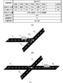
- (2A) is a diagram showing learning information
- (2B) and (2C) are schematic diagrams of roads. It is a flowchart of a support point management process.
- the support point management system of the present invention is realized by the navigation terminal 10 mounted on the vehicle C.
- the navigation terminal 10 includes a control unit 20 including a CPU, RAM, ROM, and the like and a recording medium 30.
- the control unit 20 executes a program stored in the recording medium 30 or the ROM.
- the control unit 20 executes the support point management program 21 as one of the programs.
- the vehicle C includes a GPS receiver 41, a vehicle speed sensor 42, a gyro sensor 43, an ECU (Electronic Control Unit) 44, a user I / F unit 45, a braking unit 46, and an accelerator pedal 47.
- the GPS receiver 41 receives radio waves from GPS satellites and outputs a signal for calculating the current position of the vehicle C to the controller 20 via an interface (not shown).
- the vehicle speed sensor 42 outputs a signal corresponding to the rotational speed of the wheels provided in the vehicle C.
- the control unit 20 acquires this signal via an interface (not shown) and acquires the vehicle speed.
- the gyro sensor 43 detects an angular acceleration for turning in the horizontal plane of the vehicle C, and outputs a signal corresponding to the direction of the vehicle C.
- the control unit 20 acquires this signal and acquires the traveling direction of the vehicle C.
- map information 30a is recorded.
- the map information 30a includes node data indicating the position of a node set on the road on which the vehicle C travels, shape interpolation data indicating the position of a shape interpolation point for specifying the shape of the road between the nodes, the nodes
- the link data indicating the connection of are included.
- the ECU 44 is a circuit for controlling the vehicle C.
- the ECU 44 of the present embodiment acquires a signal indicating the amount of depression of the accelerator pedal 47.
- the ECU 44 outputs a signal indicating the amount of depression of the accelerator pedal to the control unit 20.
- the ECU 44 also controls the braking unit 46.
- the braking unit 46 includes a braking device for braking the vehicle C, a control circuit for the braking device, a brake pedal, and the like.
- the braking device may generate a braking force by a friction brake, may generate a braking force by an engine brake, or may generate a braking force by a regenerative brake.
- the user I / F unit 45 is an interface unit for inputting a driver's instruction and providing various information to the driver, such as a display unit or a speaker that also serves as an input unit including a touch panel display (not shown).
- An output sound output unit is provided.
- the control unit 20 can cause the user I / F unit 45 to display the current position of the vehicle C and a map around the current position by the function of the support point management program 21. That is, the control unit 20 acquires the current position of the vehicle C, generates an image indicating a map around the current position based on the map information 30a, and outputs the image to the user I / F unit 45. As a result, the display unit of the user I / F unit 45 displays a map including the current position.
- the support point management program 21 includes a traveling road identification unit 21a, a support point acquisition unit 21b, an exclusion unit 21c, and a deceleration support unit 21d.
- the traveling road identification unit 21a is a module that causes the control unit 20 to execute a function of identifying a traveling road section where the vehicle C is traveling based on the traveling locus of the vehicle C and the map information 30a.
- the control unit 20 specifies the road section on which the vehicle C is traveling by known map matching.
- the travel locus of the vehicle C is acquired based on output signals from the vehicle speed sensor 42, the gyro sensor 43, the GPS receiver 41, and the like, and the shape of the road section is acquired based on the node data and link data of the map information 30a.
- control part 20 acquires the matching degree with a driving
- the support point acquisition unit 21b is a module that causes the control unit 20 to execute a function of acquiring a support point registered as a deceleration support target. With the function of the support point acquisition unit 21b, the control unit 20 acquires a support point that is effectively registered as a deceleration support target in the learning information DB 30b of the recording medium 30.
- FIG. 2A shows learning information recorded for each support point in the learning information DB 30b.
- the learning information is information in which for each support point, the road section where the support point exists, the position of the support point on the road section, the target flag, the travel log, and the target vehicle speed are recorded in association with each other.
- the support point is a point at which deceleration support ends, and is a point set based on a deceleration point where deceleration of the vehicle C has ended in the past.
- deceleration is completed means that the vehicle C has stopped or the vehicle C has re-accelerated.
- the case where the vehicle C stops is a case where the vehicle speed becomes equal to or lower than a predetermined threshold (for example, 3 km / hour).
- the case where the vehicle C re-accelerates is a case where the accelerator pedal is depressed after the vehicle speed is reduced by a predetermined amount (for example, 5 km / hour) or more.
- the target flag is a flag that is set to ON when the support point is a target for deceleration support, and is set to OFF when the support point is excluded from the targets for deceleration support.
- a travel log is information recorded whenever the vehicle C travels a support point. When the vehicle C decelerates at the support point, the remaining distance indicating the position of the deceleration point where the deceleration has ended is recorded as a travel log. The remaining distance is a distance from the deceleration point and the support point to the end point node of the road section where the deceleration point and the support point exist.
- the remaining distance may be a linear distance between the position of the end node of the road section, the deceleration point, and the support point, or may be a distance along a road on the road section.
- “pass” is recorded as a travel log.
- a travel log can be recorded for 20 runs. When the number of travels at a single support point is greater than 20, the oldest travel log is deleted instead of recording the latest travel log.
- FIG. 2B is a schematic diagram illustrating a state where the deceleration of the vehicle C is completed at the deceleration point A on the road section R 1 .
- the vehicle C when there is a deceleration point A within a predetermined error range (within 15 meters before and after) from the support point Q already recorded in the learning information, the vehicle C has finished decelerating at the support point Q Is considered.
- the deceleration point A is within the error range of the existing support point Q
- the remaining distance L representing the position of the deceleration point A in the learning information about the existing support point Q is recorded as a travel log.
- the position corresponding to the median value of the remaining distances L representing the positions of the plurality of deceleration points A is updated as the position of the support point Q. Is done.
- the median is the N / 2th (rounded up or down) remaining distance L counted from the larger of the remaining distances L representing the positions of N (2 or more natural numbers) recorded deceleration points A. means.
- new learning information with the deceleration point A as the support point Q is generated and added to the learning information DB 30b.
- the number of remaining distances L indicating the position of the deceleration point A recorded as the travel log means the number of times of deceleration at the support point Q
- the number of “passing” recorded as the travel log is the passage at the support point Q. Means the number of times.
- a value obtained by dividing the number of decelerations by the sum of the number of decelerations and the number of passages means the deceleration probability at the support point Q.
- the target vehicle speed is a vehicle speed targeted by the deceleration support performed at the support point Q, and the deceleration support is performed so that the vehicle speed at the support point Q becomes the target vehicle speed.
- the target vehicle speed is an average value of the vehicle speed when past deceleration at the support point Q (deceleration point A within the error range from the support point Q) is completed.
- the exclusion unit 21c provides the control unit 20 with a function of excluding the support point Q from the target of deceleration support when the vehicle C travels on a new road following the support point Q without decelerating at the support point Q. A module to be executed.
- the control unit 20 changes to the support point Q when the deceleration of the vehicle C does not end at a point within the error range (within 15 meters before and after) of the support point Q that is the target of deceleration support. It is determined that deceleration did not end.
- the control unit 20 determines that the travel road section cannot be identified by map matching of the travel road identifying unit 21a. It is determined that C is traveling on the new road. Moreover, the control part 20 excludes the said assistance point Q from the object of the deceleration assistance by setting the object flag matched with the assistance point Q in learning information by the function of the exclusion part 21c.
- the control unit 20 determines the support point Q when the number of times that the vehicle C has traveled on the new road following the support point Q is equal to or greater than the threshold without decelerating at the support point Q. Exclude from deceleration support. In the present embodiment, the control unit 20 decelerates the support point Q when the vehicle C does not decelerate at the support point Q, and when traveling on the new road following the support point Q continues two or more times. Exclude from support. The control unit 20 sets the new road flag to ON in the travel log of the learning information shown in FIG. 2B only when the vehicle C travels on the new road following the support point Q without decelerating at the support point Q. Set.
- the control unit 20 sets the new road flag to OFF in the travel log.
- the control unit 20 determines that the support point Q is a target for deceleration support when the new road flag in the latest travel log is ON and the new road flag in the previous travel log is ON.
- the deceleration support unit 21d is a module that causes the control unit 20 to execute a function of performing deceleration support for decelerating at the support point Q.
- the control unit 20 acquires the support point Q that is the target of deceleration support from the learning information DB 30b, and implements driving support when the vehicle C travels in front of the support point Q. .
- the control unit 20 sets a control section whose end point is the support point Q before the support point Q, and sets the vehicle speed of the deceleration control so as to decelerate from the current vehicle speed to the target vehicle speed in the control section. To do.
- the vehicle speed for the deceleration control is set so that the vehicle speed becomes the target vehicle speed at the support point Q.
- the ideal deceleration (for example, 0.2 G) is an ideal deceleration set based on, for example, the ride comfort of the occupant, the charging efficiency of regenerative power, the braking ability of the vehicle C, and the like. Note that deceleration means the absolute value of negative acceleration.
- the length of the control section is determined based on the current vehicle speed, the target vehicle speed, and the ideal deceleration.
- the control unit 20 causes the braking unit 46 of the vehicle C to generate a braking force so that the vehicle speed is set in advance when the vehicle C enters the control section.
- the traveling road section cannot be specified, the link data of the road section on which the vehicle C is traveling is not yet recorded in the map information 30a, and the newly constructed road section R newly established after the creation of the map information 30a. 4 can be determined that the vehicle C is traveling. In this configuration, it can be determined that the vehicle C is traveling on the new road section R 4 without waiting for the provision of the map information 30a in which information on the new road section R 4 is recorded.
- the traveling locus (straight traveling locus) when exiting from the road section R 1 to the new road section R 4 and the shape of the road composed of the road section R 1 and the left-turn road section R 2 The matching degree does not exceed the threshold.
- the degree of matching between the travel trajectory (straight trajectory) when exiting from the road section R 1 to the new road section R 4 and the shape of the road composed of the road section R 1 and the right-turn road section R 3 is a threshold value. No more. Therefore, when the user exits from the road section R 1 to the new road section R 4 , the traveling road section cannot be specified.
- control unit 20 supports the vehicle C when the number of times that the vehicle C has traveled on the new road section R 4 subsequent to the support point Q is equal to or more than a threshold value (two times) without decelerating at the support point Q.
- Point Q is excluded from the target of deceleration support.
- the support point Q is decelerated. It can be prevented from being excluded from the support. For example, when the vehicle C enters a facility near the support point Q without decelerating at the support point Q, it is possible to prevent the support point Q from being excluded from the deceleration support target.
- the support point management process is a process executed every predetermined time period or mileage period.
- the control unit 20 identifies the traveling road section in which the vehicle C is traveling every predetermined time period or traveling distance period by the function of the traveling road identifying unit 21a.
- the control unit 20 acquires the support point Q from each learning information in the learning information DB 30b by the function of the support point acquisition unit 21b, and determines whether the support point Q exists around the vehicle C (step S100).
- the periphery of the vehicle C means the periphery of the vehicle C on the planned travel route searched in advance by a known route search method.
- the vicinity of the vehicle C on the planned travel route means a range within 300 m forward from the current position on the planned travel route and within 30 m behind the current position. In the present embodiment, it is assumed that the vehicle C is traveling on a travel road section on the planned travel route.
- the control unit 20 If it is not determined that the support point Q exists around the vehicle C, the control unit 20 returns to the beginning of the support point management process (step S100). That is, it waits until the support point Q comes to exist around the vehicle C. On the other hand, when it determines with the assistance point Q existing around the vehicle C, the control part 20 determines whether the deceleration of the vehicle C was complete
- the case where the deceleration is completed means that the vehicle speed is equal to or lower than a predetermined threshold value (for example, 3 km / hour) or that the vehicle speed is decreased by a predetermined amount (for example, 5 km / hour) or more. This is when the accelerator pedal is depressed.
- the function of the exclusion unit 21c causes the control unit 20 to determine whether or not deceleration has periodically ended during the period in which the vehicle C is traveling within the error range of the support point Q. When it is detected that deceleration has ended in any period within the period in which the vehicle C is traveling within the error range, it is determined that the deceleration of the vehicle C has ended at the support point Q.
- step S105 When it is determined that the deceleration of the vehicle C is completed at the support point Q (step S105: Y), the control unit 20 records the remaining distance L indicating the position of the deceleration point A as a travel log by the function of the exclusion unit 21c. Then, the new road flag is set to OFF (step S110).
- the remaining distance L is the distance from the deceleration point A and the support point Q to the end point node S of the road section where the deceleration point A and the support point Q are present.
- the control unit 20 displays the oldest traveling log (remaining distance L or “passing”).
- the control unit 20 sets the new road flag to OFF regardless of the road section on which the vehicle C has traveled after traveling at the support point Q.
- the control unit 20 determines whether or not the deceleration probability is equal to or higher than the target threshold (for example, 80%) (step S115).
- the deceleration probability is a value obtained by dividing the number of decelerations by the sum of the number of decelerations and the number of passages. Further, the number of decelerations is the number of remaining distances L representing the position of the deceleration point A recorded as a travel log, and the number of passes is the number of “passes” recorded as a travel log.
- step S115: Y the control unit 20 learns that the target flag is turned on for the support point Q where the deceleration of the vehicle C has ended by the function of the exclusion unit 21c.
- Information is updated (step S120). That is, the control unit 20 updates the position of the support point Q, the target vehicle speed, and the target flag in the learning information. Specifically, the control unit 20 acquires a position corresponding to the median value of the remaining distance L representing the positions of the plurality of deceleration points A recorded as the learning log as the position of the new support point Q.
- control unit 20 adds the number obtained by subtracting 1 from the number of times of deceleration (number of times of deceleration-1) and the current target vehicle speed and the vehicle speed when it is determined that the deceleration is completed in step S105.
- the updated target vehicle speed is obtained by calculating the value and dividing the total value by the number of decelerations.
- the control unit 20 sets the target flag in the learning information to ON. That is, if the target flag is originally OFF, the target flag is switched to ON. If the target flag is originally ON, the target flag is kept ON. Thereby, deceleration support can be implemented at the support point Q where the vehicle C is highly likely to decelerate.
- step S115: N the control unit 20 causes the target flag to be turned off for the support point Q where the deceleration of the vehicle C is ended by the function of the exclusion unit 21c.
- the learning information is updated (step S125).
- the control unit 20 updates the target vehicle speed and the position of the support point Q as in step S120.
- step S125 the control unit 20 sets the target flag in the learning information to OFF. That is, if the target flag is ON, the target flag is switched to OFF, and if the target flag is originally OFF, the target flag remains OFF. Thereby, it is possible to prevent the vehicle C from being decelerated at the support point Q where the possibility that the vehicle C is decelerated is small.
- step S105: N when it is not determined that the deceleration of the vehicle C has been completed at the support point Q (step S105: N), the control unit 20 records “pass” as a travel log by the function of the exclusion unit 21c, and the new road The flag is set to OFF (step S130).
- the control unit 20 deletes the oldest remaining distance L or “passing”. , "Pass” is recorded as a new travel log.
- the control unit 20 sets the new road flag to OFF as an initial state.
- the control unit 20 determines whether the deceleration probability is less than the exclusion threshold (for example, 30%) (step S135).
- the control unit 20 sets the target flag for the support point Q where the deceleration has not been performed to OFF by the function of the exclusion unit 21c (step S135).
- S140 That is, if the target flag is ON, the target flag is switched to OFF, and if the target flag is originally OFF, the target flag remains OFF. Thereby, it is possible to prevent the vehicle C from being decelerated at the support point Q where the possibility that the vehicle C is decelerated is small.
- the exclusion threshold that is the deceleration probability when the target flag is switched from ON to OFF is set to a value smaller than the target threshold that is the deceleration probability when the target flag is switched from OFF to ON.
- step S135: N the control unit 20 uses the function of the exclusion unit 21c to drive the vehicle C on the new road section following the support point Q. It is determined whether or not (step S145). Specifically, after passing the support point Q, when the vehicle C has traveled a predetermined distance (for example, 100 m), if the travel road section cannot be identified by the map matching of the travel road identifying unit 21a, the vehicle C is newly established. Determine that you are driving on the road.
- a predetermined distance for example, 100 m
- step S145: N the control unit 20 uses the function of the exclusion unit 21c to start the support point management process (step S100).
- “passing” is recorded as a travel log in the learning information about the support point Q through which the vehicle C has passed, and the system waits until the vehicle C travels the support point Q next time. In this case, the new road flag corresponding to “pass” as the travel log remains set to OFF as the initial state.
- step S145: Y the control unit 20 uses the function of the exclusion unit 21c to determine the support point Q for which deceleration has not been performed.
- the new road flag of the travel log is set to ON (step S150).
- the control unit 20 determines whether or not traveling on the new road following the support point Q has continued two or more times without decelerating at the support point Q (Ste S155). Specifically, the control unit 20 excludes the support point Q from the deceleration support target when the new road flag in the latest travel log is ON and the new road flag in the previous travel log is ON. To do.
- step S155: N If it is not determined that driving on the new road following the support point Q without decelerating at the support point Q has been continued twice or more (step S155: N), the control unit 20 performs support point management. Return to the beginning of the process (step S100). That is, “passing” is recorded as a travel log in the learning information about the support point Q through which the vehicle C has passed, the new road flag for the “passing” is set to ON, and then the vehicle C Wait until you drive Q.
- step S140 the control unit 20 performs step S140. Execute. That is, if it continues two or more times on the new road following the support point Q without decelerating at the support point Q, the deceleration does not occur regardless of whether or not the deceleration probability is less than the exclusion threshold.
- the target flag for the support point Q that was not performed is set to OFF. In other words, if it continues two or more times on the new road following the support point Q without decelerating at the support point Q, it will be early without waiting for the deceleration probability to be less than the exclusion threshold.
- the target flag for the support point Q is set to OFF. Thereby, as shown in FIG. 2C, the support point Q where the new road section R 4 is newly established can be excluded from the object of the deceleration support at an early stage, and unnecessary deceleration support can be prevented from being implemented.
- the control unit 20 excludes the support point Q from the target of deceleration support. Also good. In this case, the support point Q at which the new road section R 4 is newly established can be excluded from the target for deceleration support earlier than in the embodiment.
- the control unit 20 determines whether to exclude the support point Q from the target of driving support. An operation for designating may be accepted.
- control unit 20 does not necessarily have to determine whether or not the vehicle C is traveling on the new road based on the map matching result. For example, when the navigation terminal 10 receives update data of the map information 30a from a server on the network, the control unit 20 may associate the reception date with each link data included in the update data. Then, the control unit 20 does not decelerate at the support point Q. If the reception date and time of the link data corresponding to the road section on which the vehicle C travels following the support point Q is within a predetermined period from the present, You may exclude the point Q from the object of deceleration assistance.
- the control unit 20 does not decelerate the vehicle C at the support point Q, and the number of times that the vehicle C has traveled on the new road section R 4 following the support point Q is equal to or greater than a threshold value (two times).
- the threshold value may be set according to the operation of the driver.
- the support point Q is excluded from the deceleration support target by setting the target flag to OFF, but the control unit 20 decelerates the support point Q by deleting the learning information about the support point Q. You may exclude from support object.
- the support point management process does not necessarily have to be executed in the navigation terminal 10 mounted on the vehicle C.
- the support point management process is executed in a server that acquires information indicating a travel route or a decelerated point from the vehicle C. May be.
- the support point acquisition unit may acquire a support point registered as a deceleration support target, and may acquire a support point that is effectively registered as a deceleration support target from a recording medium or a communication medium.
- the support point is a point where deceleration support is performed, and the point where deceleration support is performed may be a point where deceleration support is started or a point where deceleration support ends.
- the support point may be a point learned based on the deceleration history of the vehicle. This is because even if the support point is learned based on the deceleration history, the driving route of the driver can change due to the new construction of the new road.
- the support point may be a restriction point (a temporary stop point, a railroad crossing, etc.) on the map that needs to be decelerated. This is because even if a restriction point has been set in the past, the restriction point can be abolished along with the establishment of a new road.
- a restriction point a temporary stop point, a railroad crossing, etc.
- the exclusion means may exclude the support point from the object of the deceleration support when the vehicle travels on the new road following the support point without decelerating at the support point.
- the exclusion means identifies the road on which the vehicle is traveling at the stage where the vehicle has traveled a predetermined distance after passing through the support point, or after the predetermined period has elapsed, and if the road is a new road, It may be determined that the vehicle has traveled on a new road.
- the exclusion means obtains the vehicle speed at a stage where the vehicle has traveled a predetermined distance after passing through the support point or a stage where a predetermined period has elapsed, and travels on a road (new road) if the vehicle speed is equal to or less than a threshold value. It may be determined that it is not. This can prevent erroneous determination that the vehicle is traveling on the new road when the vehicle enters the facility after passing through the support point.
- the exclusion means is used when the traveling direction of the vehicle at the stage where the vehicle has traveled a predetermined distance after passing through the support point or after a predetermined period has deviated by more than a predetermined reference from the direction of the road where the support point exists.
- the support point may not be excluded from the deceleration support target.
- the deceleration support may be to generate a braking force in the braking portion of the vehicle regardless of the driver's operation, or to guide the driver to the deceleration timing.
- To exclude a support point from the target of deceleration support may be to delete the support point from the database in which the support point is registered, or not to delete the support point but to flag it as a target for deceleration support May be set.
- the exclusion means may determine that the road that has traveled following the support point is a road that has been defined as a new road in the map information, and has traveled on the new road following the support point. For example, when the time when a new road is established is recorded in the map information or when the data corresponding to the new road is recorded in the map information, the road on which the vehicle is running is the new road. It can be determined whether or not.
- the vehicle further includes a traveling road identifying unit that identifies a traveling road on which the vehicle is traveling based on the traveling locus of the vehicle and the map information, and the excluding unit includes a new road when the traveling road cannot be identified. It may be determined that the vehicle is running. In addition, when the traveling road cannot be specified, the information on the road on which the vehicle is traveling is not yet recorded in the map information, and the vehicle is traveling on a newly constructed road after the creation of the map information. Can be judged. In this configuration, it is possible to determine that the vehicle is traveling on the new road without waiting for the provision of map information recording information on the new road.
- the traveling road specifying means may specify a road having a shape that matches the traveling locus of the vehicle as a traveling road by known map matching.
- the exclusion means may exclude the support point from the object of the deceleration support when the vehicle has not decelerated at the support point and the number of times the vehicle has traveled on the new road following the support point exceeds a threshold value. Good.
- the support point is excluded from the target of deceleration support. Can be prevented. For example, when a vehicle enters a facility near the support point without decelerating at the support point, it is possible to prevent the support point from being excluded from the target of deceleration support.
- the method for managing support points can be applied as a program or method.
- the system, program, and method as described above may be realized as a single device, or may be realized using components shared with each part of the vehicle, and include various aspects. It is a waste.
- some changes may be made as appropriate, such as a part of software and a part of hardware.
- the invention is also established as a recording medium for a program for controlling the apparatus.
- the software recording medium may be a magnetic recording medium, a magneto-optical recording medium, or any recording medium to be developed in the future.
Landscapes
- Engineering & Computer Science (AREA)
- Radar, Positioning & Navigation (AREA)
- Remote Sensing (AREA)
- Physics & Mathematics (AREA)
- General Physics & Mathematics (AREA)
- Automation & Control Theory (AREA)
- Atmospheric Sciences (AREA)
- Life Sciences & Earth Sciences (AREA)
- Mechanical Engineering (AREA)
- Transportation (AREA)
- Navigation (AREA)
- Traffic Control Systems (AREA)
- Regulating Braking Force (AREA)
Abstract
Description
本発明は、前記課題にかんがみてなされたもので、不必要な減速支援を実施することを防止する技術の提供を目的とする。
(1)支援地点管理システムの構成:
(2)支援地点管理処理:
(3)他の実施形態:
本発明の支援地点管理システムは、車両Cに搭載されたナビゲーション端末10によって実現されている。ナビゲーション端末10は、CPU,RAM,ROM等を備える制御部20と記録媒体30とを備える。制御部20は、記録媒体30やROMに記憶されたプログラムを実行する。本実施形態において制御部20は、このプログラムの一つとして支援地点管理プログラム21を実行する。
次に、支援地点管理処理について説明する。支援地点管理処理は、所定の時間周期または走行距離周期ごとに実行される処理である。なお、支援地点管理処理を実行する期間において、走行道路特定部21aの機能により制御部20は、所定の時間周期または走行距離周期ごとに車両Cが走行している走行道路区間を特定している。まず、支援地点取得部21bの機能により制御部20は、学習情報DB30bの各学習情報から支援地点Qを取得し、車両Cの周辺に支援地点Qが存在するか否かを判定する(ステップS100)。車両Cの周辺とは、公知の経路探索手法によって予め探索された走行予定経路上における車両Cの周辺を意味する。走行予定経路上における車両Cの周辺とは、走行予定経路上における現在位置から前方300m以内かつ当該現在位置から後方30m以内の範囲を意味する。本実施形態において、走行予定経路上の走行道路区間を車両Cが走行していることとする。
支援地点Qにて減速することなく、当該支援地点Qに続いて新設道路を走行することが1回でも生じた場合に、制御部20は、当該支援地点Qを減速支援の対象から除外してもよい。この場合、前記実施形態よりも早期に、新設道路区間R4が新設された支援地点Qを減速支援の対象から除外できる。なお、車両Cが支援地点Qにて減速することなく、当該支援地点Qに続いて新設道路区間R4を走行した場合、制御部20は、支援地点Qを運転支援の対象から除外するか否かを指定する操作を受け付けてもよい。
Claims (5)
- 減速支援の対象として登録されている支援地点を取得する支援地点取得手段と、
車両が前記支援地点にて減速することなく、当該支援地点に続いて新設道路を走行した場合に、前記支援地点を前記減速支援の対象から除外する除外手段と、
を備える支援地点管理システム。 - 前記車両の走行軌跡と地図情報とに基づいて、前記車両が走行している走行道路を特定する走行道路特定手段をさらに備え、
前記除外手段は、前記走行道路が特定できない場合に、前記車両が前記新設道路を走行していると判定する、
請求項1に記載の支援地点管理システム。 - 前記除外手段は、前記車両が前記支援地点にて減速することなく、当該支援地点に続いて前記新設道路を走行した回数が閾値以上となった場合に、前記支援地点を前記減速支援の対象から除外する、
請求項1または請求項2のいずれかに記載の支援地点管理システム。 - 減速支援の対象として登録されている支援地点を取得する支援地点取得工程と、
車両が前記支援地点にて減速することなく、当該支援地点に続いて新設道路を走行した場合に、前記支援地点を前記減速支援の対象から除外する除外工程と、
を含む支援地点管理方法。 - 減速支援の対象として登録されている支援地点を取得する支援地点取得機能と、
車両が前記支援地点にて減速することなく、当該支援地点に続いて新設道路を走行した場合に、前記支援地点を前記減速支援の対象から除外する除外機能と、
をコンピュータに実行させる支援地点管理プログラム。
Priority Applications (3)
| Application Number | Priority Date | Filing Date | Title |
|---|---|---|---|
| CN201480052910.2A CN105684063B (zh) | 2013-10-21 | 2014-09-16 | 辅助地点管理系统、方法以及记录介质 |
| DE112014003728.1T DE112014003728T5 (de) | 2013-10-21 | 2014-09-16 | Unterstützungspunktverwaltungssystem, Verfahren und Programm |
| US15/026,149 US10030983B2 (en) | 2013-10-21 | 2014-09-16 | Support point management system, method, and program |
Applications Claiming Priority (2)
| Application Number | Priority Date | Filing Date | Title |
|---|---|---|---|
| JP2013218200A JP6062839B2 (ja) | 2013-10-21 | 2013-10-21 | 支援地点管理システム、方法およびプログラム |
| JP2013-218200 | 2013-10-21 |
Publications (1)
| Publication Number | Publication Date |
|---|---|
| WO2015060039A1 true WO2015060039A1 (ja) | 2015-04-30 |
Family
ID=52992644
Family Applications (1)
| Application Number | Title | Priority Date | Filing Date |
|---|---|---|---|
| PCT/JP2014/074371 Ceased WO2015060039A1 (ja) | 2013-10-21 | 2014-09-16 | 支援地点管理システム、方法およびプログラム |
Country Status (5)
| Country | Link |
|---|---|
| US (1) | US10030983B2 (ja) |
| JP (1) | JP6062839B2 (ja) |
| CN (1) | CN105684063B (ja) |
| DE (1) | DE112014003728T5 (ja) |
| WO (1) | WO2015060039A1 (ja) |
Families Citing this family (3)
| Publication number | Priority date | Publication date | Assignee | Title |
|---|---|---|---|---|
| JP6448347B2 (ja) * | 2014-12-16 | 2019-01-09 | アイシン・エィ・ダブリュ株式会社 | 減速制御システム、方法およびプログラム |
| JP7067353B2 (ja) * | 2018-08-09 | 2022-05-16 | トヨタ自動車株式会社 | 運転者情報判定装置 |
| JP7583998B2 (ja) | 2021-03-26 | 2024-11-15 | 株式会社アイシン | 走行履歴解析システム |
Citations (2)
| Publication number | Priority date | Publication date | Assignee | Title |
|---|---|---|---|---|
| JP2008070149A (ja) * | 2006-09-12 | 2008-03-27 | Denso Corp | カーナビゲーション装置 |
| JP2013114365A (ja) * | 2011-11-28 | 2013-06-10 | Mazda Motor Corp | 安全運転支援情報配信システム |
Family Cites Families (5)
| Publication number | Priority date | Publication date | Assignee | Title |
|---|---|---|---|---|
| JP4367431B2 (ja) * | 2005-10-26 | 2009-11-18 | トヨタ自動車株式会社 | 車両用運転支援システム |
| GB2440958A (en) * | 2006-08-15 | 2008-02-20 | Tomtom Bv | Method of correcting map data for use in navigation systems |
| CN101033978B (zh) * | 2007-01-30 | 2010-10-13 | 珠海市智汽电子科技有限公司 | 智能汽车辅助导航和自动兼辅助驾驶系统 |
| US8577550B2 (en) * | 2009-10-05 | 2013-11-05 | Ford Global Technologies, Llc | System for vehicle control to mitigate intersection collisions and method of using the same |
| JP5644168B2 (ja) * | 2010-04-22 | 2014-12-24 | トヨタ自動車株式会社 | 運転支援装置 |
-
2013
- 2013-10-21 JP JP2013218200A patent/JP6062839B2/ja active Active
-
2014
- 2014-09-16 DE DE112014003728.1T patent/DE112014003728T5/de not_active Withdrawn
- 2014-09-16 WO PCT/JP2014/074371 patent/WO2015060039A1/ja not_active Ceased
- 2014-09-16 CN CN201480052910.2A patent/CN105684063B/zh not_active Expired - Fee Related
- 2014-09-16 US US15/026,149 patent/US10030983B2/en active Active
Patent Citations (2)
| Publication number | Priority date | Publication date | Assignee | Title |
|---|---|---|---|---|
| JP2008070149A (ja) * | 2006-09-12 | 2008-03-27 | Denso Corp | カーナビゲーション装置 |
| JP2013114365A (ja) * | 2011-11-28 | 2013-06-10 | Mazda Motor Corp | 安全運転支援情報配信システム |
Also Published As
| Publication number | Publication date |
|---|---|
| US20160245658A1 (en) | 2016-08-25 |
| CN105684063A (zh) | 2016-06-15 |
| CN105684063B (zh) | 2018-04-20 |
| US10030983B2 (en) | 2018-07-24 |
| JP6062839B2 (ja) | 2017-01-18 |
| DE112014003728T5 (de) | 2016-05-25 |
| JP2015082123A (ja) | 2015-04-27 |
Similar Documents
| Publication | Publication Date | Title |
|---|---|---|
| CN111619577B (zh) | 服务器、车辆控制系统 | |
| JPWO2015125516A1 (ja) | 注意案内システム、方法およびプログラム | |
| JP6289480B2 (ja) | 走行情報記録システム、方法およびプログラム | |
| WO2021020154A1 (ja) | 車両制御装置 | |
| CN111006681B (zh) | 一种辅助导航方法、装置、设备和介质 | |
| JP2016133328A (ja) | ルート探索システム及びコンピュータプログラム | |
| JP6062839B2 (ja) | 支援地点管理システム、方法およびプログラム | |
| JP4816670B2 (ja) | ナビゲーション装置、ナビゲーション方法およびナビゲーションプログラム | |
| CN114802250A (zh) | 数据处理方法、装置、设备、自动驾驶车辆及介质 | |
| JP6448347B2 (ja) | 減速制御システム、方法およびプログラム | |
| CN112325898A (zh) | 路径规划方法、装置、设备和存储介质 | |
| JP6091290B2 (ja) | 区間情報管理システム、方法およびプログラム | |
| CN117508191A (zh) | 一种车道状态的确定方法、装置、终端设备和存储介质 | |
| US11768507B2 (en) | Driving control management system, driving control management method, and computer readable medium | |
| JP6221619B2 (ja) | 支援地点管理システム、方法およびプログラム | |
| JP6303582B2 (ja) | 経路案内システム、方法およびプログラム | |
| CN110070743B (zh) | 车辆驾驶辅助装置和车辆驾驶辅助方法 | |
| JP2022187273A (ja) | 情報処理装置および運転評価システム | |
| JP2023013458A (ja) | 情報処理サーバ、情報処理サーバの処理方法、プログラム | |
| JP2016136305A (ja) | 運転支援システム、方法およびプログラム | |
| JP6168811B2 (ja) | 車両制御区間学習システム、方法およびプログラム | |
| JP6324306B2 (ja) | 減速制御システム、方法およびプログラム | |
| CN112765191B (zh) | Adas数据增量发送方法、系统、电子设备及存储介质 | |
| JP6269677B2 (ja) | 運転支援システム、方法およびプログラム | |
| JP6909043B2 (ja) | 運転状態推定装置 |
Legal Events
| Date | Code | Title | Description |
|---|---|---|---|
| 121 | Ep: the epo has been informed by wipo that ep was designated in this application |
Ref document number: 14856015 Country of ref document: EP Kind code of ref document: A1 |
|
| WWE | Wipo information: entry into national phase |
Ref document number: 112014003728 Country of ref document: DE Ref document number: 1120140037281 Country of ref document: DE |
|
| WWE | Wipo information: entry into national phase |
Ref document number: 15026149 Country of ref document: US |
|
| 122 | Ep: pct application non-entry in european phase |
Ref document number: 14856015 Country of ref document: EP Kind code of ref document: A1 |