WO2015060025A1 - ガスケット - Google Patents
ガスケット Download PDFInfo
- Publication number
- WO2015060025A1 WO2015060025A1 PCT/JP2014/073613 JP2014073613W WO2015060025A1 WO 2015060025 A1 WO2015060025 A1 WO 2015060025A1 JP 2014073613 W JP2014073613 W JP 2014073613W WO 2015060025 A1 WO2015060025 A1 WO 2015060025A1
- Authority
- WO
- WIPO (PCT)
- Prior art keywords
- gasket
- lip
- protrusion
- thickness direction
- plane
- Prior art date
- Legal status (The legal status is an assumption and is not a legal conclusion. Google has not performed a legal analysis and makes no representation as to the accuracy of the status listed.)
- Ceased
Links
Images

Classifications
-
- F—MECHANICAL ENGINEERING; LIGHTING; HEATING; WEAPONS; BLASTING
- F16—ENGINEERING ELEMENTS AND UNITS; GENERAL MEASURES FOR PRODUCING AND MAINTAINING EFFECTIVE FUNCTIONING OF MACHINES OR INSTALLATIONS; THERMAL INSULATION IN GENERAL
- F16J—PISTONS; CYLINDERS; SEALINGS
- F16J15/00—Sealings
- F16J15/02—Sealings between relatively-stationary surfaces
- F16J15/021—Sealings between relatively-stationary surfaces with elastic packing
- F16J15/022—Sealings between relatively-stationary surfaces with elastic packing characterised by structure or material
- F16J15/024—Sealings between relatively-stationary surfaces with elastic packing characterised by structure or material the packing being locally weakened in order to increase elasticity
- F16J15/025—Sealings between relatively-stationary surfaces with elastic packing characterised by structure or material the packing being locally weakened in order to increase elasticity and with at least one flexible lip
-
- H—ELECTRICITY
- H01—ELECTRIC ELEMENTS
- H01R—ELECTRICALLY-CONDUCTIVE CONNECTIONS; STRUCTURAL ASSOCIATIONS OF A PLURALITY OF MUTUALLY-INSULATED ELECTRICAL CONNECTING ELEMENTS; COUPLING DEVICES; CURRENT COLLECTORS
- H01R13/00—Details of coupling devices of the kinds covered by groups H01R12/70 or H01R24/00 - H01R33/00
- H01R13/46—Bases; Cases
- H01R13/52—Dustproof, splashproof, drip-proof, waterproof, or flameproof cases
- H01R13/5219—Sealing means between coupling parts, e.g. interfacial seal
Definitions
- the present invention relates to a gasket related to sealing technology.
- the gasket of the present invention is used, for example, in the field related to automobiles, or in the field related to auxiliary equipment.
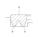
- an inner lip 61 and an outer lip 62 are provided side by side on one surface in the thickness direction (lower surface in the figure) and the other in the thickness direction.
- a gasket made of a single rubber formed with a flat surface 63 as a surface see Patent Document 1 or 2.
- This gasket is used, for example, in a connector connection part that directly fits a connector fixed to the case of one electronic device and a connector fixed to the case of the other electronic device, and foreign matter such as muddy water and dust outside the connection part. Provides a sealing function so that does not enter the inside of the connection.
- the other surface in the thickness direction is formed as a planar surface 63 as described above, and the other surface in the thickness direction formed as the planar surface 63 is on the plane (not shown) of the mating case. Since the sealing surfaces are in contact with each other, the sealing surface pressure may be insufficient depending on how the cases are tightened, and the sealing function may not be sufficiently achieved.
- the present invention can increase the seal surface pressure and suppress an increase in gasket reaction force, thereby improving the sealing performance and suppressing deformation of the counterpart case. It is an object to provide a gasket that can be used.
- a gasket according to claim 1 of the present invention is a rubber unit gasket that is mounted between two opposing members and seals between the two members, and has an inner lip on one surface in the thickness direction.
- the outer lip is provided side by side and a recess is provided in the center in the width direction of the other surface in the thickness direction, an inner protrusion and an outer protrusion are provided on both sides of the recess, and the tip of the inner lip and the tip of the inner protrusion are on a plane. It is arranged at a position shifted from each other, and the distal end portion of the outer lip and the distal end portion of the outer projection are also arranged at positions shifted from each other on a plane.
- the gasket according to claim 2 of the present invention is the gasket according to claim 1, wherein the inner lip has a tapered portion on a side surface thereof, and the inner protrusion has a straight portion connected to the tapered portion on a side surface thereof. Accordingly, the front end portion of the inner protrusion is disposed on the inner side of the gasket from the front end portion of the inner lip, the outer lip has a tapered portion on its side surface, and the outer protrusion has a straight portion connected to the tapered portion on the side surface.
- the distal end portion of the outer protrusion is disposed outside the gasket from the distal end portion of the outer lip, and the cross-sectional shape of the gasket is asymmetric in the gasket thickness direction.
- the gasket according to claim 3 of the present invention is the gasket according to claim 1 or 2, wherein the gasket is used for a connector connecting portion of an electronic device.
- the other surface in the thickness direction is a seal surface that contacts the mating case, and the other surface in the thickness direction is not formed flat, but the other surface in the thickness direction.
- a recess is provided in the center of the surface in the width direction, and an inner protrusion and an outer protrusion are provided on both sides of the recess, so that the other surface in the thickness direction is three-dimensional.
- an inner lip and an outer lip are provided side by side on one surface in the thickness direction, and the tip of the inner lip and the tip of the inner protrusion are arranged at positions shifted from each other on the plane.
- the tips of the protrusions are also arranged at positions shifted from each other on the plane.
- the seal surface pressure can be increased.
- the inner lip and the inner protrusion at positions shifted on the plane, provide a tapered portion on the side surface of the inner lip and a straight portion connected to the tapered portion on the side surface of the inner protrusion to place the inner lip and the inner protrusion on the plane.
- a tapered portion is provided on the side surface of the outer lip and the straight portion connected to the tapered portion on the side surface of the outer protrusion. It is preferable to displace the outer lip and the outer protrusion on a plane by providing, and according to these, the cross-sectional shape of the gasket is asymmetrical in the thickness direction of the gasket. It is possible to acquire.
- the gasket of the present invention is suitable for use in a connector connecting portion of an electronic device, and thereby it is possible to prevent foreign matters such as muddy water and dust outside the connecting portion from entering the inside of the connecting portion.
- this application is not limited.
- the present invention has the following effects.
- the other surface in the thickness direction of the gasket is a seal surface that contacts the mating case, and a recess is provided on the other surface in the thickness direction, and the inner protrusion and the outer protrusion on both sides of the recess.
- the other surface in the thickness direction is three-dimensional.
- an inner lip and an outer lip are provided side by side on one surface in the thickness direction, the inner lip and the inner protrusion are arranged at positions shifted on the plane, and the outer lip and the outer protrusion are also arranged at positions shifted on the plane. .
- the gasket is not so large even when compressed in the thickness direction. Does not generate reaction force.
- the inner protrusion and the outer protrusion are in close contact with the mating case with a limited area, the seal surface pressure can be increased. Therefore, according to the intended purpose of the present invention, it is possible to provide a gasket capable of increasing the seal surface pressure and suppressing the gasket reaction force from increasing, thereby improving the sealing performance and suppressing deformation of the counterpart case. Can do.
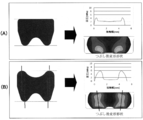
- FIG. 2A is an explanatory diagram related to a comparative example sample
- FIG. 2B is an explanatory diagram related to an example sample.
- the present invention includes the following embodiments. (1) Compared to a conventional gasket having a flat upper surface (seal surface), the upper surface side is changed to a lip shape that is asymmetrical with a concave shape on the upper surface side. Thereby, it becomes possible to suppress the reaction force and increase the crushing margin, and the effect of increasing the surface pressure (sealability) of the upper surface protrusion can be obtained. (2) Since the points on which the force is applied are shifted on the upper and lower surfaces of the gasket, the reaction force can be suppressed even if the crushing margin is increased, and a high surface pressure can be obtained. (3) Further, since the lip collapse direction is stabilized during compression, the reliability of the seal is high.
- FIG. 1 shows a cross section of the main part of a gasket 1 according to an embodiment of the present invention.
- the gasket 1 according to this embodiment is a single rubber (rubber-like elastic body) gasket that is mounted between two opposing members 51 and 52 and seals between the two members 51 and 52.
- One surface in the thickness direction (lower surface in the drawing) closely contacting the groove bottom surface 53a of the mounting groove 53 provided in the upper surface and the other surface in the thickness direction (upper surface in the drawing) contacting the flat surface 54 of the other member 52 are provided.
- the gasket 1 according to the embodiment is used, for example, in a connector connecting portion that fits a connector fixed to the case of one electronic device and a connector fixed to the case of the other electronic device.
- the case of one electronic device corresponds to the one member 51.
- the other electronic device case corresponds to the other member 52.
- the left side of the gasket 1 is outside the gasket 1 and outside the connecting portion, and the right side of the gasket 1 is inside the gasket and inside the connecting portion.
- the gasket 1 has one surface in the thickness direction as described above, and the inner lip 2 and the outer lip 3 are provided side by side on the one surface in the thickness direction.
- the gasket 1 has the other surface in the thickness direction as described above, and a recess 4 is provided at the center in the width direction of the other surface in the thickness direction, and the inner protrusion 5 and the outer protrusion 6 are formed on both sides of the recess 4. Is provided.
- the inner lip 2 and the outer lip 3 are each formed in a cross-sectional mountain shape or a cross-sectional triangle shape, and have tip portions 2a and 3a having a circular arc shape in cross section.
- the inner protrusion 5 and the outer protrusion 6 are each formed in a cross-sectional mountain shape or a triangular shape, and have end portions 5a and 6a having a circular arc shape in cross section.
- the front end portion 2a of the inner lip 2 and the front end portion 5a of the inner protrusion 5 are arranged at positions shifted from each other on the plane, and the front end portion 3a of the outer lip 3 and the front end portion 6a of the outer protrusion 6 are also shifted from each other on the plane. Is arranged.
- the inner lip 2 is provided with a tapered portion 7 on its side surface, and the inner protrusion 5 is provided with a straight portion 8 connected to the tapered portion 7 on its side surface, whereby the tip portion 5a of the inner protrusion 5 is the tip portion 2a of the inner lip 2.
- the taper portion 7 is disposed on the inner side of the gasket 1 by an amount corresponding to the gradient.
- the outer lip 3 has a tapered portion 9 on its side surface
- the outer protrusion 6 has a straight portion 10 connected to the tapered portion 9 on its side surface, so that the distal end portion 6 a of the outer protrusion 6 becomes the distal end of the outer lip 3.
- a portion corresponding to the gradient of the tapered portion 9 from the portion 3a is disposed outside the gasket 1.
- the cross-sectional shape of the gasket 1 is asymmetric in the gasket thickness direction. Moreover, the cross-sectional shape of the gasket 1 is a symmetrical shape in the gasket width direction.
- the other surface in the thickness direction is a sealing surface that comes into contact with the mating case (the other member 52), and the other surface in the thickness direction is a flat surface as in the prior art.
- an inner lip 2 and an outer lip 3 are provided side by side on one surface in the thickness direction, and the distal end 2a of the inner lip 2 and the distal end 5a of the inner projection 5 are arranged at positions shifted from each other on the plane.
- the tip 3a of the lip 3 and the tip 6a of the outer protrusion 6 are also arranged at positions shifted from each other on the plane. Accordingly, since the inner lip 2 and the inner protrusion 5 are arranged at positions shifted on the plane and the outer lip 3 and the outer protrusion 6 are also arranged at positions shifted on the plane as described above, the gasket 1 is arranged in the thickness direction. Even when compressed, it does not generate a large reaction force.
- a comparative example sample and an example sample according to the present invention were manufactured, and FEM analysis and the like were performed.
- the comparative sample has a cross-sectional shape shown in the left diagram of FIG. 2A, that is, an inner lip and an outer lip are provided side by side on one surface in the thickness direction (lower surface in the figure) and the other surface in the thickness direction (FIG.
- the upper surface) is formed as a planar surface.
- the example sample has the cross-sectional shape shown in the left diagram of FIG. 2B, that is, the cross-sectional shape described in the above-described example (FIG. 1).
- the cross-sectional shape shown in the left diagram of FIG. 2B that is, the cross-sectional shape described in the above-described example (FIG. 1).
- stress is dispersed as shown in the lower right diagram of FIG. 2 (B), and an increase in reaction force can be suppressed, and as shown in the upper right diagram of FIG. 2 (B).
- the peak value of the seal surface pressure becomes relatively large.
Landscapes
- Engineering & Computer Science (AREA)
- General Engineering & Computer Science (AREA)
- Mechanical Engineering (AREA)
- Gasket Seals (AREA)
- Connector Housings Or Holding Contact Members (AREA)
Abstract
シール面圧を高めることができ、しかもガスケット反力が増大するのを抑制することができ、もってシール性を向上させるとともに相手ケースの変形を抑制することができるガスケットを提供する。この目的を達成するため、互いに対向する二部材間に装着されて二部材間をシールするラバー単体のガスケットであって、厚み方向一方の面に内側リップおよび外側リップを並べて設けるとともに厚み方向他方の面の幅方向中央に凹みを設けて凹みの両側に内側突起および外側突起を設ける。内側リップの先端部および内側突起の先端部を平面上互いにずれた位置に配置し、外側リップの先端部および外側突起の先端部をこれも平面上互いにずれた位置に配置する。
Description
本発明は、シール技術に係るガスケットに関する。本発明のガスケットは例えば、自動車関連の分野で用いられ、またはその補機に関連する分野などで用いられる。
従来から自動車等車両における電子機器のコネクタ接続部に用いられるガスケットとして図3に示すように、その厚み方向一方の面(図では下面)に内側リップ61および外側リップ62を並べて設けるとともに厚み方向他方の面を平面状の面63として形成したラバー単体よりなるガスケットが知られている(特許文献1または2参照)。
このガスケットは例えば一方の電子機器のケースに固定されたコネクタと他方の電子機器のケースに固定されたコネクタとを直接嵌合するコネクタ接続部に用いられ、接続部外部の泥水やダスト等の異物が接続部内部へ侵入することがないようにシール機能を発揮する。
しかしながらこのガスケットでは、上記したように厚み方向他方の面が平面状の面63として形成され、この平面状の面63として形成された厚み方向他方の面が相手ケースの平面(図示せず)に接触するシール面とされるため、ケース同士の締付具合などによっては、シール面圧が不足し、シール機能が十分に果たされないことがある。
この点につき、シール面圧を高めるには、シール面にリップを追加してガスケットのつぶし代を増大させることが有効であるが、このようにシール面にリップを追加してつぶし代を増大させると、ガスケットの断面形状が厚み方向に対称な形状となって、つぶし時に生じるガスケット反力が増大するため、相手ケース(樹脂製であることが多い)側に変形が生じ、却ってシール性が低下してしまうことがある。
本発明は以上の点に鑑みて、シール面圧を高めることができ、しかもガスケット反力が増大するのを抑制することができ、もってシール性を向上させるとともに相手ケースの変形を抑制することができるガスケットを提供することを目的とする。
上記目的を達成するため、本発明の請求項1によるガスケットは、互いに対向する二部材間に装着されて前記二部材間をシールするラバー単体のガスケットであって、厚み方向一方の面に内側リップおよび外側リップを並べて設けるとともに厚み方向他方の面の幅方向中央に凹みを設けて前記凹みの両側に内側突起および外側突起を設け、前記内側リップの先端部および前記内側突起の先端部を平面上互いにずれた位置に配置し、前記外側リップの先端部および前記外側突起の先端部をこれも平面上互いにずれた位置に配置したことを特徴とする。
また、本発明の請求項2によるガスケットは、上記した請求項1記載のガスケットにおいて、前記内側リップはその側面にテーパー部を備えるとともに前記内側突起はその側面に前記テーパー部に連なるストレート部を備えることにより前記内側突起の先端部は前記内側リップの先端部より当該ガスケットの内側に配置され、前記外側リップはその側面にテーパー部を備えるとともに前記外側突起はその側面に前記テーパー部に連なるストレート部を備えることにより前記外側突起の先端部は前記外側リップの先端部より当該ガスケットの外側に配置され、当該ガスケットの断面形状はガスケット厚み方向に非対称形状とされていることを特徴とする。
また、本発明の請求項3によるガスケットは、上記した請求項1または2記載のガスケットにおいて、当該ガスケットは電子機器のコネクタ接続部に用いられることを特徴とする。
上記構成を備える本発明のガスケットにおいては、その厚み方向他方の面が相手ケースに接触するシール面とされ、この厚み方向他方の面が平面状に形成されるのではなく、この厚み方向他方の面の幅方向中央に凹みが設けられるとともに凹みの両側に内側突起および外側突起が設けられることにより、この厚み方向他方の面が立体化されている。一方、厚み方向一方の面には内側リップおよび外側リップが並べて設けられており、内側リップの先端部および内側突起の先端部は平面上互いにずれた位置に配置され、外側リップの先端部および外側突起の先端部はこれも平面上互いにずれた位置に配置されている。したがってこのように内側リップおよび内側突起が平面上ずれた位置に配置されるとともに外側リップおよび外側突起がこれも平面上ずれた位置に配置されているため、ガスケットは厚み方向に圧縮されても、それほど大きな反力を発生することがない。
またその一方で、内側突起および外側突起がそれぞれ、限られた面積で相手ケースに密接するため、シール面圧を高めることが可能とされる。
内側リップおよび内側突起を平面上ずれた位置に配置するには、内側リップの側面にテーパー部を設けるとともに内側突起の側面にテーパー部に連なるストレート部を設けることにより内側リップおよび内側突起を平面上ずらすのが好適であり、また同様に、外側リップおよび外側突起を平面上互いにずれた位置に配置するには、外側リップの側面にテーパー部を設けるとともに外側突起の側面にテーパー部に連なるストレート部を設けることにより外側リップおよび外側突起を平面上ずらすのが好適であり、これらによれば、ガスケットの断面形状がガスケット厚み方向に非対称な形状とされるため、上記した反力増大抑制の効果を獲得することが可能とされる。
また、本発明のガスケットは、電子機器のコネクタ接続部に用いられるのに適しており、これにより接続部外部の泥水やダスト等の異物が接続部内部へ侵入するのを抑制することが可能される。但し、この用途は限定的なものではない。
本発明は、以下の効果を奏する。
すなわち、本発明においては以上説明したように、ガスケットの厚み方向他方の面が相手ケースに接触するシール面とされ、この厚み方向他方の面に凹みが設けられ凹みの両側に内側突起および外側突起が設けられることにより、厚み方向他方の面が立体化されている。一方、厚み方向一方の面には内側リップおよび外側リップが並べて設けられ、内側リップおよび内側突起は平面上ずれた位置に配置され、外側リップおよび外側突起も平面上ずれた位置に配置されている。したがってこのように内側リップおよび内側突起が平面上ずれた位置に配置されるとともに外側リップおよび外側突起も平面上ずれた位置に配置されているため、ガスケットは厚み方向に圧縮されても、それほど大きな反力を発生しない。また内側突起および外側突起がそれぞれ、限られた面積で相手ケースに密接するため、シール面圧を高めることが可能とされている。したがってこれらにより本発明所期の目的どおり、シール面圧を高め、ガスケット反力が増大するのを抑制し、もってシール性を向上させるとともに相手ケースの変形を抑制することができるガスケットを提供することができる。
本発明には、以下の実施形態が含まれる。
(1)上面(シール面)を平面状とした従来ガスケットに対し、上面側を凹み形状として上下非対称のリップ形状に変更する。これにより、反力を抑えてつぶし代を増やすことが可能となり、上面突起部の面圧(シール性)アップの効果が得られる。
(2)ガスケット上面および下面で力のかかる点がずれているので、つぶし代を大きくしても反力を抑えられ、高い面圧も得られるので、シール性に優れる。
(3)また、圧縮時、リップの倒れ方向が安定化するので、シールの信頼性も高い。
(4)圧縮時、リップの横方向に応力が生じるので、溝側面に接触したストレート部を押し付ける力がかかり、面接触部のシール性を向上させることができる。
(5)本発明によれば、面圧・シール性アップ、反力低減、充填率低減、圧縮割れ性向上に係る効果が得られる。
(1)上面(シール面)を平面状とした従来ガスケットに対し、上面側を凹み形状として上下非対称のリップ形状に変更する。これにより、反力を抑えてつぶし代を増やすことが可能となり、上面突起部の面圧(シール性)アップの効果が得られる。
(2)ガスケット上面および下面で力のかかる点がずれているので、つぶし代を大きくしても反力を抑えられ、高い面圧も得られるので、シール性に優れる。
(3)また、圧縮時、リップの倒れ方向が安定化するので、シールの信頼性も高い。
(4)圧縮時、リップの横方向に応力が生じるので、溝側面に接触したストレート部を押し付ける力がかかり、面接触部のシール性を向上させることができる。
(5)本発明によれば、面圧・シール性アップ、反力低減、充填率低減、圧縮割れ性向上に係る効果が得られる。
つぎに本発明の実施例を図面にしたがって説明する。
図1は、本発明の実施例に係るガスケット1の要部断面を示している。当該実施例に係るガスケット1は、互いに対向する二部材51,52間に装着されて前記二部材51,52間をシールするラバー(ゴム状弾性体)単体のガスケットであって、一方の部材51に設けた装着溝53の溝底面53aに密接する厚み方向一方の面(図では下面)と、他方の部材52の平面54に密接する厚み方向他方の面(図では上面)とを有している。また当該実施例に係るガスケット1は例えば、一方の電子機器のケースに固定されたコネクタと他方の電子機器のケースに固定されたコネクタとを嵌合するコネクタ接続部に用いられ、接続部外部の泥水やダスト等の異物が接続部内部へ侵入することがないようにシール機能を発揮するものであって、この場合、一方の電子機器のケース(装着側ケース)が上記一方の部材51に相当し、他方の電子機器のケース(相手ケース)が上記他方の部材52に相当する。図1では、ガスケット1の左側がガスケット1の外側であって接続部外部とされ、ガスケット1の右側がガスケットの内側であって接続部内部とされる。
ガスケット1は、上記したように厚み方向一方の面を有し、この厚み方向一方の面に内側リップ2および外側リップ3が並べて設けられている。
また、ガスケット1は、上記したように厚み方向他方の面を有し、この厚み方向他方の面の幅方向中央に凹み4が設けられ、この凹み4の両側に内側突起5および外側突起6が設けられている。
内側リップ2および外側リップ3はそれぞれ断面山形ないし断面三角形に形成されるとともに、断面円弧形の先端部2a,3aを有している。
内側突起5および外側突起6はこれもそれぞれ断面山形ないし断面三角形に形成され、断面円弧形の先端部5a,6aを有している。
内側リップ2の先端部2aおよび内側突起5の先端部5aは平面上互いにずれた位置に配置され、外側リップ3の先端部3aおよび外側突起6の先端部6aはこれも平面上互いにずれた位置に配置されている。
また、内側リップ2はその側面にテーパー部7を備えるとともに内側突起5はその側面にテーパー部7に連なるストレート部8を備え、これにより内側突起5の先端部5aは内側リップ2の先端部2aよりテーパー部7の勾配分、ガスケット1の内側に配置されている。
また同様に、外側リップ3はその側面にテーパー部9を備えるとともに外側突起6はその側面にテーパー部9に連なるストレート部10を備え、これにより外側突起6の先端部6aは外側リップ3の先端部3aよりテーパー部9の勾配分、ガスケット1の外側に配置されている。
また、ガスケット1の断面形状は、ガスケット厚み方向に非対称な形状とされている。また、ガスケット1の断面形状は、ガスケット幅方向に対称な形状とされている。
上記構成を備えるガスケット1においては、その厚み方向他方の面が相手ケース(他方の部材52)に対し接触するシール面とされ、この厚み方向他方の面が上記先行技術のように平面状の面として形成されるのではなく、この厚み方向他方の面に凹み4が設けられるとともに凹み4の両側に内側突起5および外側突起6が設けられて、厚み方向他方の面が立体化されている。一方、厚み方向一方の面には内側リップ2および外側リップ3が並べて設けられており、内側リップ2の先端部2aおよび内側突起5の先端部5aは平面上互いにずれた位置に配置され、外側リップ3の先端部3aおよび外側突起6の先端部6aはこれも平面上互いにずれた位置に配置されている。したがってこのように内側リップ2および内側突起5が平面上ずれた位置に配置されるとともに外側リップ3および外側突起6がこれも平面上ずれた位置に配置されているため、ガスケット1は厚み方向に圧縮されても、それほど大きな反力を発生しない。
またその一方で、内側突起5および外側突起6がそれぞれ、その先端部5a,6aにおける限られた面積で相手ケースに密接するため、シール面圧を高めることが可能とされている。
これらの点に関し、本願発明者らは、上記作用効果を確認するため、比較試験を実施したので、以下にその内容および結果について説明する。
比較試験は、比較例サンプルおよび本発明に係る実施例サンプルを製作し、FEM解析などを実施した。
比較例サンプルは、図2(A)の左図に示す断面形状を有し、すなわち厚み方向一方の面(図では下面)に内側リップおよび外側リップが並べて設けられるとともに厚み方向他方の面(図では上面)が平面状の面として形成されている。このような形状であると、図2(A)の右下図に示すようにリップ2,3の根元部近傍にて比較的大きな応力集中が発生し、大きな反力が発生しやすく、また、図2(A)の右上図に示すようにシール面圧のピーク値が比較的小さい。
これに対し、実施例サンプルは、図2(B)の左図に示す断面形状を有し、すなわち上記実施例(図1)で説明した断面形状を有している。このような形状であると、図2(B)の右下図に示すように応力が分散し、反力の増大を抑制することができ、また、図2(B)の右上図に示すようにシール面圧のピーク値が比較的大きくなる。
したがって、シール面圧を高めることができ、しかもガスケット反力が増大するのを抑制することができることを確認することができた。
1 ガスケット
2 内側リップ
2a,3a,5a,6a 先端部
3 外側リップ
4 凹み
5 内側突起
6 外側突起
7,9 テーパー部
8,10 ストレート部
51 一方の部材
52 他方の部材
53 装着溝
53a溝底面
54 平面
2 内側リップ
2a,3a,5a,6a 先端部
3 外側リップ
4 凹み
5 内側突起
6 外側突起
7,9 テーパー部
8,10 ストレート部
51 一方の部材
52 他方の部材
53 装着溝
53a溝底面
54 平面
Claims (3)
- 互いに対向する二部材間に装着されて前記二部材間をシールするラバー単体のガスケットであって、
厚み方向一方の面に内側リップおよび外側リップを並べて設けるとともに厚み方向他方の面の幅方向中央に凹みを設けて前記凹みの両側に内側突起および外側突起を設け、
前記内側リップの先端部および前記内側突起の先端部を平面上互いにずれた位置に配置し、
前記外側リップの先端部および前記外側突起の先端部をこれも平面上互いにずれた位置に配置したことを特徴とするガスケット。 - 請求項1記載のガスケットにおいて、
前記内側リップはその側面にテーパー部を備えるとともに前記内側突起はその側面に前記テーパー部に連なるストレート部を備えることにより前記内側突起の先端部は前記内側リップの先端部より当該ガスケットの内側に配置され、
前記外側リップはその側面にテーパー部を備えるとともに前記外側突起はその側面に前記テーパー部に連なるストレート部を備えることにより前記外側突起の先端部は前記外側リップの先端部より当該ガスケットの外側に配置され、
当該ガスケットの断面形状はガスケット厚み方向に非対称形状とされていることを特徴とするガスケット。 - 請求項1または2記載のガスケットにおいて、
当該ガスケットは電子機器のコネクタ接続部に用いられることを特徴とするガスケット。
Applications Claiming Priority (2)
| Application Number | Priority Date | Filing Date | Title |
|---|---|---|---|
| JP2013-219124 | 2013-10-22 | ||
| JP2013219124A JP2015081627A (ja) | 2013-10-22 | 2013-10-22 | ガスケット |
Publications (1)
| Publication Number | Publication Date |
|---|---|
| WO2015060025A1 true WO2015060025A1 (ja) | 2015-04-30 |
Family
ID=52992630
Family Applications (1)
| Application Number | Title | Priority Date | Filing Date |
|---|---|---|---|
| PCT/JP2014/073613 Ceased WO2015060025A1 (ja) | 2013-10-22 | 2014-09-08 | ガスケット |
Country Status (2)
| Country | Link |
|---|---|
| JP (1) | JP2015081627A (ja) |
| WO (1) | WO2015060025A1 (ja) |
Cited By (1)
| Publication number | Priority date | Publication date | Assignee | Title |
|---|---|---|---|---|
| EP4350179A1 (en) * | 2022-10-04 | 2024-04-10 | Tyco Electronics Japan G.K. | Sealing element and connector assembly |
Families Citing this family (1)
| Publication number | Priority date | Publication date | Assignee | Title |
|---|---|---|---|---|
| JP7591454B2 (ja) * | 2021-04-01 | 2024-11-28 | ヒロセ電機株式会社 | ケーブルコネクタ |
Citations (4)
| Publication number | Priority date | Publication date | Assignee | Title |
|---|---|---|---|---|
| JP2002295683A (ja) * | 2001-03-28 | 2002-10-09 | Nok Corp | あり溝用シール |
| JP2004180824A (ja) * | 2002-12-02 | 2004-07-02 | Pegasus Sewing Mach Mfg Co Ltd | ミシン用ガスケット及びそれを使用したミシン |
| JP2011023290A (ja) * | 2009-07-17 | 2011-02-03 | Yazaki Corp | 防水構造 |
| WO2011075372A2 (en) * | 2009-12-18 | 2011-06-23 | Caterpillar Inc. | Press in place seal |
-
2013
- 2013-10-22 JP JP2013219124A patent/JP2015081627A/ja active Pending
-
2014
- 2014-09-08 WO PCT/JP2014/073613 patent/WO2015060025A1/ja not_active Ceased
Patent Citations (4)
| Publication number | Priority date | Publication date | Assignee | Title |
|---|---|---|---|---|
| JP2002295683A (ja) * | 2001-03-28 | 2002-10-09 | Nok Corp | あり溝用シール |
| JP2004180824A (ja) * | 2002-12-02 | 2004-07-02 | Pegasus Sewing Mach Mfg Co Ltd | ミシン用ガスケット及びそれを使用したミシン |
| JP2011023290A (ja) * | 2009-07-17 | 2011-02-03 | Yazaki Corp | 防水構造 |
| WO2011075372A2 (en) * | 2009-12-18 | 2011-06-23 | Caterpillar Inc. | Press in place seal |
Cited By (1)
| Publication number | Priority date | Publication date | Assignee | Title |
|---|---|---|---|---|
| EP4350179A1 (en) * | 2022-10-04 | 2024-04-10 | Tyco Electronics Japan G.K. | Sealing element and connector assembly |
Also Published As
| Publication number | Publication date |
|---|---|
| JP2015081627A (ja) | 2015-04-27 |
Similar Documents
| Publication | Publication Date | Title |
|---|---|---|
| US9441664B2 (en) | Seal washer | |
| US10612660B2 (en) | Gasket | |
| KR102001873B1 (ko) | 금속 시일 | |
| JP5234116B2 (ja) | 2材質複合ガスケット | |
| CN101115941B (zh) | 垫圈及两部件间的密封结构 | |
| JP5692504B2 (ja) | ガスケット | |
| CN107250629B (zh) | 金属垫片 | |
| WO2010047165A1 (ja) | ガスケット | |
| US20110169228A1 (en) | Sealing gasket | |
| WO2012056768A1 (ja) | ガスケット | |
| CN110537042A (zh) | 正负压密封垫 | |
| CN104755774A (zh) | 球窝接头用防尘罩 | |
| WO2014061122A1 (ja) | シールワッシャ付きナット | |
| WO2018074194A1 (ja) | 防水コネクタ | |
| WO2015060025A1 (ja) | ガスケット | |
| JP5029831B2 (ja) | ガスケット | |
| JP5932940B2 (ja) | ラバーガスケット | |
| CN102472391B (zh) | 密封圈和具有密封圈的装置 | |
| JP2013189052A (ja) | 履帯ピンシール | |
| WO2018135341A1 (ja) | ガスケット | |
| KR20090094506A (ko) | 오일씰 | |
| JP2016191425A (ja) | 密封装置 | |
| JP2004360716A (ja) | ガスケット | |
| JP2007315476A (ja) | ガスケット | |
| CN205383269U (zh) | 用于球节的防尘罩 |
Legal Events
| Date | Code | Title | Description |
|---|---|---|---|
| 121 | Ep: the epo has been informed by wipo that ep was designated in this application |
Ref document number: 14856247 Country of ref document: EP Kind code of ref document: A1 |
|
| NENP | Non-entry into the national phase |
Ref country code: DE |
|
| 122 | Ep: pct application non-entry in european phase |
Ref document number: 14856247 Country of ref document: EP Kind code of ref document: A1 |