WO2015059999A1 - 冷蔵庫 - Google Patents
冷蔵庫 Download PDFInfo
- Publication number
- WO2015059999A1 WO2015059999A1 PCT/JP2014/072217 JP2014072217W WO2015059999A1 WO 2015059999 A1 WO2015059999 A1 WO 2015059999A1 JP 2014072217 W JP2014072217 W JP 2014072217W WO 2015059999 A1 WO2015059999 A1 WO 2015059999A1
- Authority
- WO
- WIPO (PCT)
- Prior art keywords
- refrigerator
- leg
- main body
- door
- leg portion
- Prior art date
- Legal status (The legal status is an assumption and is not a legal conclusion. Google has not performed a legal analysis and makes no representation as to the accuracy of the status listed.)
- Ceased
Links
Images





Classifications
-
- F—MECHANICAL ENGINEERING; LIGHTING; HEATING; WEAPONS; BLASTING
- F25—REFRIGERATION OR COOLING; COMBINED HEATING AND REFRIGERATION SYSTEMS; HEAT PUMP SYSTEMS; MANUFACTURE OR STORAGE OF ICE; LIQUEFACTION SOLIDIFICATION OF GASES
- F25D—REFRIGERATORS; COLD ROOMS; ICE-BOXES; COOLING OR FREEZING APPARATUS NOT OTHERWISE PROVIDED FOR
- F25D23/00—General constructional features
-
- F—MECHANICAL ENGINEERING; LIGHTING; HEATING; WEAPONS; BLASTING
- F25—REFRIGERATION OR COOLING; COMBINED HEATING AND REFRIGERATION SYSTEMS; HEAT PUMP SYSTEMS; MANUFACTURE OR STORAGE OF ICE; LIQUEFACTION SOLIDIFICATION OF GASES
- F25D—REFRIGERATORS; COLD ROOMS; ICE-BOXES; COOLING OR FREEZING APPARATUS NOT OTHERWISE PROVIDED FOR
- F25D23/00—General constructional features
- F25D23/10—Arrangements for mounting in particular locations, e.g. for built-in type, for corner type
Definitions
- the present invention relates to a refrigerator.
- the refrigerator includes a refrigerator body having a heat insulating box body filled with a foam heat insulating material between an inner box whose front face is open and an outer box covering the outside of the inner box, and a door for opening and closing the opening of the inner box.
- the bottom part of the refrigerator main body is provided with a leg part protruding to the side of the outer box and the front of the door. Thereby, the refrigerator is stably supported.
- the present invention aims to provide a refrigerator that can be installed stably and can improve convenience.
- the present invention includes a refrigerator body having a heat insulating box having an opening on the front surface, a door for opening and closing the opening, and a leg provided at the bottom of the refrigerator body.
- the leg portion protrudes forward from the front surface of the refrigerator main body and protrudes laterally from the side surface of the refrigerator main body, and the amount of protrusion from the side surface of the refrigerator main body is defined in advance. It is characterized by being able to be smaller than the lower limit of the space.
- the present invention is characterized in that in the refrigerator configured as described above, the leg portion is arranged behind the front surface of the door. According to this configuration, the leg portion is hidden behind the door with respect to the line of sight from above the user.
- the present invention is characterized in that, in the refrigerator configured as described above, the leg portion is screwed into the refrigerator main body so as to be rotatable, and the protrusion amount is variable according to the rotation position of the leg portion. Yes.
- the present invention is characterized in that, in the refrigerator having the above-described configuration, the outer peripheral surface of the leg portion is formed of an inclined surface that is inclined inward as it goes upward.
- the present invention provides the refrigerator having the above-described configuration, wherein the door is pivotally supported on one of the left and right sides, and is provided with a compressor and a weight made of metal that operate the refrigeration cycle behind the bottom of the refrigerator body on the other side of the left and right. It is characterized by that.
- the amount of protrusion from the side surface of the refrigerator body is made smaller than the lower limit value of the heat radiation space on the side of the refrigerator body, thereby stably installing the refrigerator while reducing the installation area of the refrigerator. can do.
- the front view of the refrigerator which concerns on 1st Embodiment of this invention Side view of the refrigerator according to the first embodiment of the present invention.
- Side surface sectional drawing which shows the bottom part of the refrigerator which concerns on 1st Embodiment of this invention.
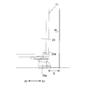
- Side surface sectional drawing which shows the bottom right part of the refrigerator which concerns on 1st Embodiment of this invention.
- Front sectional drawing which shows the bottom right part of the refrigerator which concerns on 1st Embodiment of this invention.
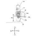
- the front view which shows the bottom right part of the refrigerator which concerns on 1st Embodiment of this invention.
- the top view which shows the bottom part of the refrigerator which concerns on 2nd Embodiment of this invention.
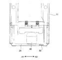
- the rear view which shows the bottom part back of the refrigerator which concerns on 2nd Embodiment of this invention.
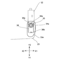
- the top view of the leg part vicinity of the refrigerator which concerns on 3rd Embodiment of this invention.
- the top view of the leg part vicinity of the refrigerator which concerns on 3rd Embodiment of this invention.
- the top view of the leg part vicinity of the refrigerator which concerns on 3rd Embodiment of this invention.
- Side surface sectional drawing which shows the bottom right part of the refrigerator which concerns on 4th Embodiment of this invention.
- FIG. 1 is a front view of the refrigerator 1 according to the first embodiment
- FIG. 2 is a side view of the refrigerator 1. Note that the right hand side of the user standing in front of the refrigerator 1 is the X1 direction, the left hand side is the X2 direction, the front of the refrigerator 1 is the Y1 direction, and the rear is the Y2 direction.
- the refrigerator 1 includes a refrigerator main body 11 and leg portions 33 a and 33 b that support the refrigerator main body 11.
- the refrigerator body 11 has a heat insulating box 15 filled with a foam heat insulating material (not shown) between the opened inner box 12 and the outer box 13 covering the outside of the inner box 12.
- the inner box 12 is made of a resin molded product, and is divided into a plurality of cooling chambers whose front surfaces are open.
- the freezer compartment 2 is arranged on the upper stage of the inner box 12, and the refrigerator compartment 3 is arranged on the lower stage.
- a machine room 14 is provided below the refrigerator body 11.
- the machine room 14 is arranged outside the heat insulating box 15 and includes a compressor 40.
- a refrigeration cycle including a compressor 40 and a heat exchanger (not shown) generates cold air and distributes the cold air to the freezer compartment 2 and the refrigerator compartment 3 through a duct (not shown). Thereby, the refrigeration temperature or freezing temperature required in each chamber is obtained.
- a compressor substrate 20 that supports the compressor 40 is disposed at the bottom of the refrigerator body 11.
- Legs 33 b are provided at the rear of the compressor substrate 20.
- the leg part 33b may provide a wheel in order to move the refrigerator 1 easily.
- FIG. 3 is an enlarged side sectional view showing the bottom of the refrigerator 1.
- the refrigerator compartment 3 is provided with a door 23.
- the door 23 is rotatably attached to the right side (X1 direction) of the opening of the refrigerator compartment 3 by a pivot part 23a.
- a gasket 23b is provided on the back surface of the door 23 along the peripheral portion.
- a magnetic material is provided inside the gasket 23b. Thereby, the back surface of the door 23 is pressure-bonded to the front surface of the inner box 12 via the gasket 23b.
- the freezer compartment 2 is similarly provided with a door 22.
- a weight 50 made of metal is provided inside the heat insulating foam (not shown) between the inner box 12 and the outer box 13.
- the weight 50 is disposed on the opposite side (X2 side) to the side (X1 direction) on which the pivotal support portion 23a that pivotally supports the door 23 is provided in the left-right direction, and on the rear side (Y2 side) of the refrigerator main body 1.
- the compressor 40 is also arranged on the opposite side (X2 side) from the pivotal support 23a in the left-right direction.
- the weight 50 is disposed at a predetermined position by superposing thin metal plates (for example, iron plates).
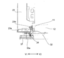
- FIG. 4 and 5 are a side sectional view and a front sectional view showing the right side of the bottom of the refrigerator 1.
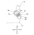
- FIG. 6 is a top view of the vicinity of the leg portion 33a.
- a bracket 32 protruding forward is attached to the front bottom of the refrigerator main body 11.
- the bracket 32 is provided with a columnar pivot 23a of the door 23 so as to protrude upward.
- a bolt 34 is screwed and fixed behind the pivotal support 23a of the bracket 32.
- the screw hole 33c of the leg part 33a is screwed into the bolt 34, and the leg part 33a is rotatably arranged.
- the height can be adjusted by rotating the leg 33a. Since the bolt 34 is disposed in front of the front surface of the refrigerator main body 11, the leg portion 33 a protrudes from the front surface of the refrigerator main body 11.
- the distance from the rotation shaft 34a of the leg 33a to the outer peripheral surface varies depending on the position in the circumferential direction in the range from the minimum distance R1 to the maximum distance R2.
- the leg part 33a can be protruded from the side surface of the refrigerator main body 11 according to a rotation position, and the protrusion amount can be varied.
- the leg portion 33a is disposed behind the front surface of the door 23. That is, the leg 33a does not protrude from the front surface of the door 23 even if the rotational position is changed. Thereby, the leg part 33a hides in the lower part of the door 23 with respect to the line of sight from a user's upper direction, and the beauty
- the protruding amount of the leg portion 33a from the side surface of the refrigerator main body 11 is lower than the lower limit value of the heat radiation space S. Is also getting bigger.
- the lower limit value of the heat radiation space S indicates the minimum distance between the side surface of the refrigerator main body 11 and the wall surface W in the room necessary for heat radiation of the refrigerator 1 and is defined in advance by the description of the instruction manual or the like.
- the leg portion 33a is arranged on the inner side than the side surface of the refrigerator main body 11.
- the protrusion amount from the side surface of the refrigerator main body 11 of the leg part 33a is variable according to a rotation position between the maximum value and the minimum value, and can be made smaller than the lower limit of the heat radiation space S.
- the leg portion 33a when the leg portion 33a is disposed at the rotation position indicated by the solid line in FIG. 6, the leg portion 33a protrudes from the side surface of the refrigerator body 11 with a protrusion amount (for example, 7 mm) smaller than the lower limit value of the heat radiation space S. It protrudes from the front surface of the main body 11 with the maximum protrusion amount. Thereby, stability of refrigerator 1 can be made high with a small installation area.
- a protrusion amount for example, 7 mm
- the lower limit value of the heat radiation space S is a value that varies depending on the model and capacity of the refrigerator 1, for example, a level 20 mm away from the outer surface of the refrigerator main body 11.
- the leg portion 33a is composed of an inclined surface that is inclined inward as the outer peripheral surface is directed upward. Thereby, the lower part of the leg part 33a has a large ground contact surface, and can support the refrigerator main body 11 stably. Further, the upper portion of the leg portion 33a is easily hidden from the line of sight from above the user. Thereby, the beauty
- FIG. 7 is a front view of the bottom right side of the refrigerator 1 packaged in the packaging box 61.
- the protruding amount of the leg portion 33a is smaller than the gap C between the packaging box 61 and the refrigerator main body 11. Since the refrigerator 1 rattles in the packaging box 61 during transportation or the like, the refrigerator 1 is accommodated in the packaging box 61 via the buffer material 63. Moreover, the clearance gap C is provided between the side surface of the refrigerator main body 11, and the packaging box 61, and the refrigerator 1 and the packaging box 61 are prevented from being rubbed and damaged.
- the protrusion amount of the leg portion 33a smaller than the gap C (for example, 10 mm), the leg portion 33a can be prevented from being rubbed and damaged by the packaging box 61.
- the installation area at the time of installation of the refrigerator 1 is made small by making the protrusion amount from the side surface of the refrigerator main body 11 smaller than the lower limit value of the heat radiation space S on the side of the refrigerator main body 11 defined in advance.
- the refrigerator 1 can be installed stably.
- the leg part 33a is distribute
- leg part 33a since the outer peripheral surface of the leg part 33a is arranged behind the front surface of the door 23 (Y2 side), the leg part 33a is hidden under the door 23 with respect to the line of sight from above the user, and the aesthetic appearance of the refrigerator 1 Will improve. Moreover, there is no possibility that the user may get caught in the leg 33a on the front side of the refrigerator 1.
- the leg portion 33a is screwed into the refrigerator main body 11 and is rotatably arranged, and the protrusion amount varies depending on the rotation position of the leg portion 33a. Thereby, the protrusion amount can be changed according to an installation place, and the convenience of the refrigerator 1 can be improved.
- the leg portion 33a is composed of an inclined surface that is inclined inward as the outer peripheral surface is directed upward. Thereby, the lower part of the leg part 33a has a large ground contact surface, and can support the refrigerator main body 11 stably. Further, the upper portion of the leg portion 33a is easily hidden from the line of sight from above the user. Thereby, the beauty
- FIG. 8 is a top sectional view showing the bottom of the refrigerator 1 according to the second embodiment
- FIG. 9 is a rear view showing the bottom of the refrigerator 1 according to the second embodiment.
- the same parts as those in the first embodiment shown in FIGS. 1 to 7 are denoted by the same reference numerals, and the description thereof is omitted.
- the second embodiment is provided with a weight 50 made of metal on the compressor substrate 20.
- the weight 50 is arranged on the opposite side (X2 side) to the side (X1 direction) on which the pivotal support portion 23a for pivotally supporting the door 23 is provided, and is arranged behind the refrigerator main body 1 (Y2 side). Thereby, even when the doors 22 and 23 are opened and closed, the center of gravity of the refrigerator 1 is on the center side, and the refrigerator 1 can be erected stably. Moreover, since the weight 50 is distribute
- ⁇ Third Embodiment> 10 to 12 are top views of the vicinity of the legs of the refrigerator according to the third embodiment.
- the same parts as those in the first embodiment shown in FIGS. 1 to 7 are denoted by the same reference numerals, and the description thereof is omitted.
- a cylindrical fixing portion 35 is fixed to the lower end of the bolt 34 (see FIG. 4) so as not to rotate with respect to the bolt 34.
- a plurality of concave portions 35 a are formed on the outer peripheral surface of the fixed portion 35 at equal intervals in the circumferential direction.
- a concave rail portion 38 is provided on the upper surface of the leg portion 33a, and the rail portion 38 is formed so that the width in the short direction is substantially the same as the diameter of the fixed portion 35. Accordingly, the leg portion 33a can be moved in the front-rear direction (Y1-Y2 direction) along the rail portion 38 in a rotatable manner. Further, the rail portion 38 is provided with convex portions 38a and 38b at both ends in the longitudinal direction. When the convex portions 38a, 38b and the concave portion 35a are fitted, the leg portion 33a is fixed in the circumferential direction.
- the leg portion 33a can be slid and fixed in the front-rear direction (Y1-Y2 direction) (see FIGS. 10 and 11). Moreover, the protrusion amount from the side surface of the refrigerator main body 11 can also be changed by rotating the leg part 33a (refer FIG. 12).
- FIG. 13 is a side sectional view showing the right side of the bottom of the refrigerator 1 according to the fourth embodiment.
- the same parts as those in the first embodiment shown in FIGS. 1 to 7 are denoted by the same reference numerals, and the description thereof is omitted.
- a groove portion 37 extending in the axial direction is provided side by side in the circumferential direction on the outer peripheral surface of the leg portion 13.
- the present invention is not limited to the above-described embodiments, and various modifications are possible. Embodiments obtained by appropriately combining technical means disclosed in different embodiments are also included in the present invention. Included in the technical scope. Moreover, it is good also as a fixed type which cannot rotate the leg part 33a.
- the present invention can be used for a refrigerator in which a refrigerator body is supported by legs.
Landscapes
- Engineering & Computer Science (AREA)
- Chemical & Material Sciences (AREA)
- Combustion & Propulsion (AREA)
- Physics & Mathematics (AREA)
- Mechanical Engineering (AREA)
- Thermal Sciences (AREA)
- General Engineering & Computer Science (AREA)
- Refrigerator Housings (AREA)
Abstract
本発明は、脚部33aが冷蔵庫本体11の前面から前方(Y1側)に突出するとともに冷蔵庫本体11の側面から側方に突出し、冷蔵庫本体11の側面からの突出量を予め規定される冷蔵庫本体11の側方の放熱スペースSの下限値よりも小さくできる。
Description
本発明は、冷蔵庫に関する。
従来の冷蔵庫は特許文献1、2に開示されている。この冷蔵庫は前面が開口した内箱と内箱の外側を覆う外箱との間に発泡断熱材を充填した断熱箱体を有する冷蔵庫本体と、内箱の開口部を開閉する扉とを備える。冷蔵庫本体の底部には外箱の側方及び扉の前方に突出した脚部が設けられている。これにより、冷蔵庫が安定して支持されている。
上記従来の冷蔵庫によると、冷蔵庫本体からの脚部の突出量を大きくすると、安定性が向上する。しかしながら、冷蔵庫の設置スペースが広くなるため設置場所が制限されるとともに、使用者が脚部に躓き易くなる。このため、冷蔵庫の利便性が悪くなる問題があった。
本発明は安定して設置できるとともに利便性を向上できる冷蔵庫を提供することを目的とする。
上記目的を達成するために本発明は、前面に開口部を開口した断熱箱体を有する冷蔵庫本体と、前記開口部を開閉する扉とを備え、前記冷蔵庫本体の底部に脚部を設けた冷蔵庫において、前記脚部が前記冷蔵庫本体の前面から前方に突出するとともに前記冷蔵庫本体の側面から側方に突出し、前記冷蔵庫本体の側面からの突出量を予め規定される前記冷蔵庫本体の側方の放熱スペースの下限値よりも小さくできることを特徴としている。
また、本発明は、上記構成の冷蔵庫において、前記脚部が前記扉の前面よりも後方に配されることを特徴としている。この構成によると、使用者の上方からの視線に対して脚部が扉の下部に隠れる。
また、本発明は、上記構成の冷蔵庫において、前記脚部は前記冷蔵庫本体と螺合して回転可能に配され、前記脚部の回転位置に応じて前記突出量を可変にしたことを特徴としている。
また、本発明は、上記構成の冷蔵庫において、前記脚部の外周面が上方に向かうに従って内側に傾斜する傾斜面から成ることを特徴としている。
また、本発明は、上記構成の冷蔵庫において、前記扉が左右の一方で枢支され、前記冷蔵庫本体の左右の他方であって底部後方に冷凍サイクルを運転する圧縮機及び金属から成る錘を設けたことを特徴としている。
本発明によると、冷蔵庫本体の側面からの突出量を予め規定される冷蔵庫本体の側方の放熱スペースの下限値よりも小さくすることにより、冷蔵庫の設置面積を小さくしながら安定して冷蔵庫を設置することができる。
<第1実施形態>
以下に本発明の実施形態を図面を参照して説明する。図1は第1実施形態に係る冷蔵庫1の正面図であり、図2は冷蔵庫1の側面図である。なお、冷蔵庫1の正面に立った使用者の右手側をX1方向、左手側をX2方向とし、冷蔵庫1の前方をY1方向、後方をY2方向とする。
以下に本発明の実施形態を図面を参照して説明する。図1は第1実施形態に係る冷蔵庫1の正面図であり、図2は冷蔵庫1の側面図である。なお、冷蔵庫1の正面に立った使用者の右手側をX1方向、左手側をX2方向とし、冷蔵庫1の前方をY1方向、後方をY2方向とする。
冷蔵庫1は冷蔵庫本体11と冷蔵庫本体11を支持する脚部33a、33bとを備える。冷蔵庫本体11は開口した内箱12と内箱12の外側を覆う外箱13との間に発泡断熱材(不図示)を充填した断熱箱体15を有している。内箱12は樹脂成形品から成り、前面を開口した複数の冷却室に区分けして形成される。内箱12の上段には冷凍室2が配され、下段には冷蔵室3が配される。
冷蔵庫本体11の下部には機械室14が設けられる。機械室14は断熱箱体15の外部に配され、圧縮機40を内装している。圧縮機40と熱交換器(不図示)を含む冷凍サイクルが冷気を生成し、ダクト(不図示)を通じて冷凍室2及び冷蔵室3に冷気を分配する。これにより、各室において必要とされる冷蔵温度または冷凍温度が得られる。
冷蔵庫本体11の底部には圧縮機40を支持する圧縮機基板20が配置されている。圧縮機基板20の後部には脚部33bが設けられている。なお、脚部33bは冷蔵庫1を容易に移動させるために車輪を設けてもよい。
図3は冷蔵庫1の底部を拡大して示す側面断面図である。冷蔵室3には扉23が設けられている。扉23は冷蔵室3の開口部の右側(X1方向)において枢支部23aによって回転可能に取り付けられている。また、扉23の背面には周部に沿ってガスケット23bが設けられている。ガスケット23bの内部には磁性体が設けられている。これにより、扉23の背面がガスケット23bを介して内箱12の前面に圧着する。なお、冷凍室2にも同様に扉22が設けられている。
内箱12と外箱13の間の断熱発泡材(不図示)内部には金属から成る錘50が設けられている。錘50は左右方向において扉23を枢支する枢支部23aが設けられた側(X1方向)とは反対側(X2側)であって、冷蔵庫本体1の後方(Y2側)に配されている。また、圧縮機40も同様に左右方向において枢支部23aとは反対側(X2側)に配されている。なお、錘50は薄い金属板(例えば、鉄板)を重ね合わせて所定位置に配される。
これにより、扉22、23を開いたときに枢支部23aに扉23の荷重が集中するが、錘50及び圧縮機40によって冷蔵庫1の重心が中心側に寄り、冷蔵庫1を安定して起立させることができる。
図4、図5は冷蔵庫1の底部右方を示す側面断面図及び正面断面図である。また、図6は脚部33a近傍の上面図を示している。冷蔵庫本体11の底面前部には前方に突出するブラケット32が取り付けられる。ブラケット32には扉23の柱状の枢支部23aが上方に突出して設けられる。ブラケット32の枢支部23aよりも後方にはボルト34が螺合して固定される。
ボルト34には脚部33aのネジ孔33cが螺合し、脚部33aが回転可能に配される。脚部33aを回転して高さ調整を行うことができる。ボルト34は冷蔵庫本体11の前面よりも前方に配置されるため、脚部33aは冷蔵庫本体11の前面から突出する。
また、脚部33aの回転軸34aから外周面までの距離は最小距離R1から最大距離R2までの範囲で周方向の位置に応じて異なる。これにより、脚部33aを回転位置に応じて冷蔵庫本体11の側面から突出させることができるとともに突出量を可変することができる。
このとき、図6に実線で示すように最大距離R2の方向を前方(Y1方向)に向けた際に脚部33aは扉23の前面よりも後方に配置される。即ち、脚部33aは回転位置を可変しても扉23の前面から突出しないようになっている。これにより、使用者の上方からの視線に対して脚部33aが扉23の下部に隠れ、冷蔵庫1の美観が向上する。また、冷蔵庫1の前面側で脚部33aに使用者が足を引っかける虞もない。
また、図6に一点鎖線で示すように、最大距離R2の方向を右方(X1方向)に向けた際に脚部33aの冷蔵庫本体11の側面からの突出量は放熱スペースSの下限値よりも大きくなっている。放熱スペースSの下限値は冷蔵庫1の放熱ために必要な冷蔵庫本体11の側面と室内の壁面Wとの最小距離を示し、取扱説明書の記載等により予め規定される。
また、最小距離R1の方向を右方(X1方向)に向けた際に脚部33aは冷蔵庫本体11の側面よりも内側に配される。これにより、脚部33aの冷蔵庫本体11の側面からの突出量が最大値と最小値との間で回転位置に応じて可変され、放熱スペースSの下限値よりも小さくできる。これにより、冷蔵庫1の据え付け時の設置面積が小さくなり、冷蔵庫1の設置場所が制限されないため利便性が向上する。
なお、本実施形態では脚部33aは図6に実線で示す回転位置に配置した際に、冷蔵庫本体11の側面から放熱スペースSの下限値よりも小さい突出量(例えば、7mm)で突出し、冷蔵庫本体11の前面から最大の突出量で突出している。これにより、冷蔵庫1の安定性を小さい設置面積で高くすることができる。
また、壁面Wに対して放熱スペースSの下限値より近くに冷蔵庫1を設置した場合、庫内の食品から奪った熱を冷蔵庫1が放熱し難くなる。このため、冷蔵庫1の庫内が冷えにくくなり、電気消費量が多くなる。放熱スペースSの下限値は冷蔵庫1の機種及び容量により異なる値であり、例えば、冷蔵庫本体11の外面から側方に20mm離れたレベルをいう。
脚部33aは外周面が上方に向かうに従って内側に傾斜する傾斜面から成る。これにより、脚部33aの下部は接地面が大きく、冷蔵庫本体11を安定して支持することができる。また、脚部33aの上部は使用者の上方からの視線に対して隠れ易くなる。これにより、冷蔵庫1の美観がより向上する。
図7は包装箱61に包装された冷蔵庫1の底部右方の正面図である。最大距離R2の方向を前方(Y1方向)に向けた際に脚部33aの突出量は包装箱61と冷蔵庫本体11との隙間Cより小さくなる。冷蔵庫1は運搬時等に冷蔵庫1が包装箱61内でがたつくため、冷蔵庫1は緩衝材63を介して包装箱61内に収納されている。また、冷蔵庫本体11の側面と包装箱61との間に隙間Cを設けて冷蔵庫1と包装箱61が擦れて損傷するのを防いでいる。脚部33aの突出量を隙間C(例えば、10mm)よりも小さくすることにより、脚部33aが包装箱61と擦れて損傷するのを防ぐことができる。
本実施形態によると、冷蔵庫本体11の側面からの突出量を予め規定される冷蔵庫本体11の側方の放熱スペースSの下限値よりも小さくすることにより、冷蔵庫1の据え付け時の設置面積を小さくしながら、安定して冷蔵庫1を設置することができる。また、脚部33aは冷蔵庫本体11の前面より前方に配されているため、冷蔵庫1の前後方向(Y1-Y2方向)が脚部33aにより安定して支持される。
また、脚部33aの外周面が扉23の前面より後方(Y2側)に配されるため、使用者の上方からの視線に対して脚部33aが扉23の下部に隠れ、冷蔵庫1の美観が向上する。また、冷蔵庫1の前面側で脚部33aに使用者が足を引っかける虞もない。
また、脚部33aは冷蔵庫本体11と螺合して回転可能に配され、脚部33aの回転位置に応じて突出量が可変する。これにより、設置場所に応じて突出量を可変させて冷蔵庫1の利便性を向上させることができる。
脚部33aは外周面が上方に向かうに従って内側に傾斜する傾斜面から成る。これにより、脚部33aの下部は接地面が大きく、冷蔵庫本体11を安定して支持することができる。また、脚部33aの上部は使用者の上方からの視線に対して隠れ易くなる。これにより、冷蔵庫1の美観がより向上する。
<第2実施形態>
図8は第2実施形態に係る冷蔵庫1の底部を示す上面断面図であり、図9は第2実施形態に係る冷蔵庫1の底部を示す背面図である。なお、前述の図1~図7に示す第1実施形態と同様の部分には同一符号を付して説明を省略する。第1実施形態に対して第2実施形態は圧縮機基板20上に金属から成る錘50が設けられている。
図8は第2実施形態に係る冷蔵庫1の底部を示す上面断面図であり、図9は第2実施形態に係る冷蔵庫1の底部を示す背面図である。なお、前述の図1~図7に示す第1実施形態と同様の部分には同一符号を付して説明を省略する。第1実施形態に対して第2実施形態は圧縮機基板20上に金属から成る錘50が設けられている。
錘50は扉23を枢支する枢支部23aが設けられた側(X1方向)とは反対側(X2側)であって、冷蔵庫本体1の後方(Y2側)に配されている。これにより、扉22、23の開閉時においても冷蔵庫1の重心が中心側にあり、冷蔵庫1を安定して起立させることができる。また、第1実施形態よりも錘50が冷蔵庫本体11の底部側に配されているため、冷蔵庫1をより安定して起立させることができる。
<第3実施形態>
図10~図12は第3実施形態に係る冷蔵庫の脚部近傍の上面図である。なお、前述の図1~図7に示す第1実施形態と同様の部分には同一符号を付して説明を省略する。第1実施形態に対して第3実施形態はボルト34(図4参照)の下端に円筒状の固定部35がボルト34に対して回転不能に固定されている。固定部35の外周面には凹部35aが周方向に等間隔で複数形成されている。
図10~図12は第3実施形態に係る冷蔵庫の脚部近傍の上面図である。なお、前述の図1~図7に示す第1実施形態と同様の部分には同一符号を付して説明を省略する。第1実施形態に対して第3実施形態はボルト34(図4参照)の下端に円筒状の固定部35がボルト34に対して回転不能に固定されている。固定部35の外周面には凹部35aが周方向に等間隔で複数形成されている。
また、脚部33aの上面には凹状のレール部38が設けられ、レール部38は短手方向の幅が固定部35の径と略同一に形成されている。これにより、脚部33aを回転可能にレール部38に沿って前後方向(Y1-Y2方向)に移動させることができる。また、レール部38は長手方向の両端部に凸部38a、38bが設けられている。凸部38a、38bと凹部35aとが嵌合したとき脚部33aは周方向に固定される。
これにより、脚部33aを前後方向(Y1-Y2方向)にスライドさせて固定することができる(図10、図11参照)。また、脚部33aを回転させることにより、冷蔵庫本体11の側面からの突出量を変更することもできる(図12参照)。
<第4実施形態>
図13は第4実施形態に係る冷蔵庫1の底部右方を示す側面断面図である。なお、前述の図1~図7に示す第1実施形態と同様の部分には同一符号を付して説明を省略する。第1実施形態に対して第4実施形態は脚部13の外周面に軸方向に延びる溝部37が周方向に並設されている。これにより、脚部33aを回転させるとき脚部33aの外周面が滑り難くなり利便性が向上する。
図13は第4実施形態に係る冷蔵庫1の底部右方を示す側面断面図である。なお、前述の図1~図7に示す第1実施形態と同様の部分には同一符号を付して説明を省略する。第1実施形態に対して第4実施形態は脚部13の外周面に軸方向に延びる溝部37が周方向に並設されている。これにより、脚部33aを回転させるとき脚部33aの外周面が滑り難くなり利便性が向上する。
なお、本発明は上述した各実施形態に限定されるものではなく、種々の変更が可能であり、異なる実施形態にそれぞれ開示された技術的手段を適宜組み合わせて得られる実施形態についても本発明の技術的範囲に含まれる。また、脚部33aを回転不能な固定式としてもよい。
本発明によると、脚部により冷蔵庫本体が支持される冷蔵庫に利用することができる。
1 冷蔵庫
2 冷凍室
3 冷蔵室
11 冷蔵庫本体
12 内箱
13 外箱
14 機械室
15 断熱箱体
20 圧縮機基板
22、23 扉
23a 枢支部
23b ガスケット
32 前脚ブラケット
33a、33b 脚部
33c ネジ孔
34 ボルト
35 固定部
35a 凹部
34a 回転軸
37 溝部
38 レール部
38a、38b 凸部
40 圧縮機
50 錘
2 冷凍室
3 冷蔵室
11 冷蔵庫本体
12 内箱
13 外箱
14 機械室
15 断熱箱体
20 圧縮機基板
22、23 扉
23a 枢支部
23b ガスケット
32 前脚ブラケット
33a、33b 脚部
33c ネジ孔
34 ボルト
35 固定部
35a 凹部
34a 回転軸
37 溝部
38 レール部
38a、38b 凸部
40 圧縮機
50 錘
Claims (5)
- 前面に開口部を開口した断熱箱体を有する冷蔵庫本体と、前記開口部を開閉する扉とを備え、前記冷蔵庫本体の底部に脚部を設けた冷蔵庫において、前記脚部が前記冷蔵庫本体の前面から前方に突出するとともに前記冷蔵庫本体の側面から側方に突出し、前記冷蔵庫本体の側面からの突出量を予め規定される前記冷蔵庫本体の側方の放熱スペースの下限値よりも小さくできることを特徴とする冷蔵庫。
- 前記脚部が前記扉の前面よりも後方に配されることを特徴とする請求項1に記載の冷蔵庫。
- 前記脚部は前記冷蔵庫本体と螺合して回転可能に配され、前記脚部の回転位置に応じて前記突出量を可変にしたことを特徴とする請求項1または請求項2に記載の冷蔵庫。
- 前記脚部の外周面が上方に向かうに従って内側に傾斜する傾斜面から成ることを特徴とする請求項1~請求項3のいずれかに記載の冷蔵庫。
- 前記扉が左右の一方で枢支され、前記冷蔵庫本体の左右の他方であって底部後方に冷凍サイクルを運転する圧縮機及び金属から成る錘を設けたことを特徴とする請求項1~請求項4のいずれかに記載の冷蔵庫。
Applications Claiming Priority (2)
| Application Number | Priority Date | Filing Date | Title |
|---|---|---|---|
| JP2013219497A JP5778739B2 (ja) | 2013-10-22 | 2013-10-22 | 冷蔵庫 |
| JP2013-219497 | 2013-10-22 |
Publications (1)
| Publication Number | Publication Date |
|---|---|
| WO2015059999A1 true WO2015059999A1 (ja) | 2015-04-30 |
Family
ID=52512158
Family Applications (1)
| Application Number | Title | Priority Date | Filing Date |
|---|---|---|---|
| PCT/JP2014/072217 Ceased WO2015059999A1 (ja) | 2013-10-22 | 2014-08-26 | 冷蔵庫 |
Country Status (3)
| Country | Link |
|---|---|
| JP (1) | JP5778739B2 (ja) |
| CN (1) | CN204154051U (ja) |
| WO (1) | WO2015059999A1 (ja) |
Families Citing this family (3)
| Publication number | Priority date | Publication date | Assignee | Title |
|---|---|---|---|---|
| JP6609424B2 (ja) * | 2015-05-29 | 2019-11-20 | アクア株式会社 | 冷蔵庫 |
| JP6614950B2 (ja) * | 2015-12-04 | 2019-12-04 | シャープ株式会社 | 冷蔵庫 |
| CN107084585B (zh) * | 2017-04-25 | 2019-06-28 | 合肥华凌股份有限公司 | 箱式设备 |
Citations (7)
| Publication number | Priority date | Publication date | Assignee | Title |
|---|---|---|---|---|
| JPS58165583U (ja) * | 1982-04-30 | 1983-11-04 | 株式会社日立製作所 | 冷蔵庫 |
| JPS59184084U (ja) * | 1983-05-26 | 1984-12-07 | 三菱電機株式会社 | 支持脚体 |
| JPH04347431A (ja) * | 1991-05-24 | 1992-12-02 | Daikin Ind Ltd | 圧縮機の振動減衰装置 |
| JPH0559183U (ja) * | 1991-06-07 | 1993-08-06 | 松下冷機株式会社 | 冷蔵庫の脚構造 |
| JP2001289551A (ja) * | 2000-04-10 | 2001-10-19 | Matsushita Refrig Co Ltd | 冷蔵庫 |
| JP2004037008A (ja) * | 2002-07-04 | 2004-02-05 | Nippon Light Metal Co Ltd | 保冷用収納庫 |
| JP2007139256A (ja) * | 2005-11-16 | 2007-06-07 | Matsushita Electric Ind Co Ltd | 冷蔵庫 |
-
2013
- 2013-10-22 JP JP2013219497A patent/JP5778739B2/ja active Active
-
2014
- 2014-08-26 WO PCT/JP2014/072217 patent/WO2015059999A1/ja not_active Ceased
- 2014-10-10 CN CN201420584920.8U patent/CN204154051U/zh not_active Expired - Fee Related
Patent Citations (7)
| Publication number | Priority date | Publication date | Assignee | Title |
|---|---|---|---|---|
| JPS58165583U (ja) * | 1982-04-30 | 1983-11-04 | 株式会社日立製作所 | 冷蔵庫 |
| JPS59184084U (ja) * | 1983-05-26 | 1984-12-07 | 三菱電機株式会社 | 支持脚体 |
| JPH04347431A (ja) * | 1991-05-24 | 1992-12-02 | Daikin Ind Ltd | 圧縮機の振動減衰装置 |
| JPH0559183U (ja) * | 1991-06-07 | 1993-08-06 | 松下冷機株式会社 | 冷蔵庫の脚構造 |
| JP2001289551A (ja) * | 2000-04-10 | 2001-10-19 | Matsushita Refrig Co Ltd | 冷蔵庫 |
| JP2004037008A (ja) * | 2002-07-04 | 2004-02-05 | Nippon Light Metal Co Ltd | 保冷用収納庫 |
| JP2007139256A (ja) * | 2005-11-16 | 2007-06-07 | Matsushita Electric Ind Co Ltd | 冷蔵庫 |
Also Published As
| Publication number | Publication date |
|---|---|
| JP2015081717A (ja) | 2015-04-27 |
| CN204154051U (zh) | 2015-02-11 |
| JP5778739B2 (ja) | 2015-09-16 |
Similar Documents
| Publication | Publication Date | Title |
|---|---|---|
| US7984955B2 (en) | Refrigerator door opening device and refrigerator having the same | |
| US20140097733A1 (en) | Refrigerator and filler thereof | |
| KR20080079112A (ko) | 냉장고 | |
| JP5778739B2 (ja) | 冷蔵庫 | |
| JP5957169B2 (ja) | 冷蔵庫 | |
| WO2010092626A1 (ja) | 冷蔵庫 | |
| WO2017002345A1 (ja) | 冷蔵庫 | |
| WO2017163295A1 (ja) | 冷蔵庫 | |
| WO2014136518A1 (ja) | 保冷庫 | |
| US20140220880A1 (en) | Shroud for refrigerator | |
| CN204100686U (zh) | 冷藏库 | |
| JP2019132568A (ja) | 冷蔵庫 | |
| JP6194482B2 (ja) | 冷蔵庫 | |
| KR20130138088A (ko) | 냉장고 | |
| KR20120039886A (ko) | 냉장고 | |
| JP2008051484A (ja) | 冷蔵庫 | |
| JP2017161106A (ja) | 冷蔵庫扉用取付棚及び冷蔵庫 | |
| JP2013100943A (ja) | 冷蔵庫 | |
| KR102185718B1 (ko) | 냉장고 | |
| JP5378322B2 (ja) | 冷蔵庫 | |
| CN113959153B (zh) | 冰箱 | |
| WO2017002310A1 (ja) | 冷蔵庫 | |
| JP2013108706A (ja) | 冷蔵庫 | |
| JP7079063B2 (ja) | 冷蔵庫 | |
| KR20110064740A (ko) | 냉장고 |
Legal Events
| Date | Code | Title | Description |
|---|---|---|---|
| 121 | Ep: the epo has been informed by wipo that ep was designated in this application |
Ref document number: 14856023 Country of ref document: EP Kind code of ref document: A1 |
|
| NENP | Non-entry into the national phase |
Ref country code: DE |
|
| 122 | Ep: pct application non-entry in european phase |
Ref document number: 14856023 Country of ref document: EP Kind code of ref document: A1 |