WO2015056456A1 - 圧縮機、及びガスタービン - Google Patents
圧縮機、及びガスタービン Download PDFInfo
- Publication number
- WO2015056456A1 WO2015056456A1 PCT/JP2014/053149 JP2014053149W WO2015056456A1 WO 2015056456 A1 WO2015056456 A1 WO 2015056456A1 JP 2014053149 W JP2014053149 W JP 2014053149W WO 2015056456 A1 WO2015056456 A1 WO 2015056456A1
- Authority
- WO
- WIPO (PCT)
- Prior art keywords
- rotor
- casing
- bleed
- compressor
- extraction
- Prior art date
- Legal status (The legal status is an assumption and is not a legal conclusion. Google has not performed a legal analysis and makes no representation as to the accuracy of the status listed.)
- Ceased
Links
Images

Classifications
-
- F—MECHANICAL ENGINEERING; LIGHTING; HEATING; WEAPONS; BLASTING
- F04—POSITIVE - DISPLACEMENT MACHINES FOR LIQUIDS; PUMPS FOR LIQUIDS OR ELASTIC FLUIDS
- F04D—NON-POSITIVE-DISPLACEMENT PUMPS
- F04D27/00—Control, e.g. regulation, of pumps, pumping installations or pumping systems specially adapted for elastic fluids
- F04D27/02—Surge control
- F04D27/0207—Surge control by bleeding, bypassing or recycling fluids
- F04D27/023—Details or means for fluid extraction
-
- F—MECHANICAL ENGINEERING; LIGHTING; HEATING; WEAPONS; BLASTING
- F02—COMBUSTION ENGINES; HOT-GAS OR COMBUSTION-PRODUCT ENGINE PLANTS
- F02C—GAS-TURBINE PLANTS; AIR INTAKES FOR JET-PROPULSION PLANTS; CONTROLLING FUEL SUPPLY IN AIR-BREATHING JET-PROPULSION PLANTS
- F02C6/00—Plural gas-turbine plants; Combinations of gas-turbine plants with other apparatus; Adaptations of gas-turbine plants for special use
- F02C6/04—Gas-turbine plants providing heated or pressurised working fluid for other apparatus, e.g. without mechanical power output
- F02C6/06—Gas-turbine plants providing heated or pressurised working fluid for other apparatus, e.g. without mechanical power output providing compressed gas
- F02C6/08—Gas-turbine plants providing heated or pressurised working fluid for other apparatus, e.g. without mechanical power output providing compressed gas the gas being bled from the gas-turbine compressor
-
- F—MECHANICAL ENGINEERING; LIGHTING; HEATING; WEAPONS; BLASTING
- F02—COMBUSTION ENGINES; HOT-GAS OR COMBUSTION-PRODUCT ENGINE PLANTS
- F02C—GAS-TURBINE PLANTS; AIR INTAKES FOR JET-PROPULSION PLANTS; CONTROLLING FUEL SUPPLY IN AIR-BREATHING JET-PROPULSION PLANTS
- F02C7/00—Features, components parts, details or accessories, not provided for in, or of interest apart form groups F02C1/00 - F02C6/00; Air intakes for jet-propulsion plants
- F02C7/08—Heating air supply before combustion, e.g. by exhaust gases
-
- F—MECHANICAL ENGINEERING; LIGHTING; HEATING; WEAPONS; BLASTING
- F04—POSITIVE - DISPLACEMENT MACHINES FOR LIQUIDS; PUMPS FOR LIQUIDS OR ELASTIC FLUIDS
- F04D—NON-POSITIVE-DISPLACEMENT PUMPS
- F04D29/00—Details, component parts, or accessories
- F04D29/40—Casings; Connections of working fluid
- F04D29/52—Casings; Connections of working fluid for axial pumps
- F04D29/522—Casings; Connections of working fluid for axial pumps especially adapted for elastic fluid pumps
-
- F—MECHANICAL ENGINEERING; LIGHTING; HEATING; WEAPONS; BLASTING
- F04—POSITIVE - DISPLACEMENT MACHINES FOR LIQUIDS; PUMPS FOR LIQUIDS OR ELASTIC FLUIDS
- F04D—NON-POSITIVE-DISPLACEMENT PUMPS
- F04D27/00—Control, e.g. regulation, of pumps, pumping installations or pumping systems specially adapted for elastic fluids
- F04D27/02—Surge control
- F04D27/0207—Surge control by bleeding, bypassing or recycling fluids
- F04D27/0215—Arrangements therefor, e.g. bleed or by-pass valves
Definitions
- the present invention relates to a compressor that includes a rotor that rotates about an axis, and a casing that surrounds the rotor, and a gas turbine that includes the compressor.
- a compressor that includes a rotor that rotates about an axis to compress a gas such as air, and a casing that surrounds the rotor.
- This compressor employs a bleed structure for guiding a part of the gas compressed by the rotor to the outside.
- Patent Document 1 discloses a compressor that employs such a bleed structure.
- an extraction chamber communicating with a main flow path of air (compressed air) and a pipe for guiding the air in the extraction chamber to the outside are formed.
- the extraction chamber is an annular space centered on the rotor.
- the pipe extends from the bleed chamber toward the radially outer side with respect to the rotor.
- the air bleed from the main flow path into the bleed chamber has a flow swirling in the circumferential direction as the rotor rotates.
- the inventors have found that the flow rate in the circumferential direction of the air becomes non-uniform in the vicinity of the piping inside the extraction chamber by analysis using CFD (Computational Fluid Dynamics). Specifically, the local mass flow rate of air tended to increase on the front side in the rotational direction of the rotor with respect to the piping inside the extraction chamber.
- CFD Computer Fluid Dynamics
- An object of the present invention is to provide a compressor capable of reducing the non-uniformity of the flow rate of the fluid in the vicinity of the bleed nozzle and suppressing the decrease in the operation efficiency of the compressor.
- the compressor includes a rotor that rotates about an axis, a rotor casing that surrounds the rotor from an outer peripheral side and forms a main flow path between the rotor and the rotor.
- a bleed chamber casing provided on the outer peripheral side of the casing and forming a bleed chamber communicating with the main flow passage between the rotor casing and the bleed chamber casing is connected to the bleed chamber casing from the outer peripheral side, and the inside of the bleed chamber is provided inside.
- a bleed nozzle that guides the fluid to the outside, and the radial interval between the bleed chamber casing and the rotor casing is greater than the front side in the rotational direction of the rotor with respect to the position where the bleed nozzle is provided.
- the rear side in the rotational direction of the rotor is larger.
- the flow area is reduced corresponding to the decrease in the fluid flow rate on the front side in the rotation direction of the rotor with respect to the extraction nozzle, and the flow rate of the fluid is increased on the rear side in the rotation direction.
- the flow path area increases.
- a radial interval between the extraction chamber casing and the rotor casing, and the interval on the rear side in the rotation direction with respect to the extraction nozzle is gradually increased toward the front side in the rotation direction of the rotor. It is good also as a structure currently formed.
- the shape corresponds to the gradually increasing fluid flow rate, and the uniformity of the fluid flow rate can be further improved.
- a radial interval between the extraction chamber casing and the rotor casing, and the interval on the front side in the rotation direction with respect to the extraction nozzle is gradually decreased toward the front side in the rotation direction of the rotor. It is good also as a structure currently formed. According to the said structure, it becomes a shape corresponding to the flow volume of the fluid which decreases gradually, and can improve the uniformity of the flow volume of the fluid more.
- the inner peripheral surface of the extraction nozzle and the radially outer surface of the extraction chamber may be connected by a smooth curved surface that is convex toward the fluid flow path side. According to the said structure, it becomes possible to suppress peeling of the fluid which flows through an extraction chamber, and a fluid can be smoothly introduce
- a gas turbine according to an aspect of the present invention for achieving the above object includes a compressor that compresses air as the fluid by the rotation of the rotor, and any one of the above compressors and the compressor.
- a combustor that combusts fuel in compressed air to generate combustion gas; and a turbine that is driven by the combustion gas from the combustor.
- the non-uniformity in the flow rate of the fluid in the vicinity of the extraction nozzle can be reduced, and the stall that occurs near the tip of the moving blade can be suppressed.
- the stall By suppressing the stall, a surge caused in the entire fluid flow is also suppressed, and a decrease in the operating efficiency of the compressor can be suppressed.
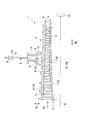
- the gas turbine according to the present embodiment compresses the outside air Ao to generate compressed air A, and the fuel F supplied from the fuel supply source is mixed with the compressed air A and burned. And a plurality of combustors 20 that generate the combustion gas G and a turbine 21 that is driven by the combustion gas G.
- the compressed air A is referred to as air A.
- Both the compressor 1 and the turbine 21 have rotors 2 and 22 that rotate around a rotation axis Ar, and cylindrical casings 3 and 23 that cover the rotors 2 and 22.
- the rotor 2 of the compressor 1 and the rotor 22 of the turbine 21 rotate around the same rotation axis Ar and are connected to each other.
- the casing 3 of the cylindrical compressor 1 forms a main flow path 4 through which air A flows in cooperation with the rotor 2 of the compressor 1.
- the cylindrical turbine casing 23 forms a main flow path 24 through which the combustion gas G flows in cooperation with the rotor 22 of the turbine 21.
- the plurality of combustors 20 are fixed to the turbine casing 23 at equal intervals in the circumferential direction Dc around the rotation axis Ar.
- a direction in which the rotation axis Ar extends is referred to as an axial direction Da.
- a radial direction based on the rotation axis Ar is defined as a radial direction Dr.
- a direction away from the rotation axis Ar in the radial direction Dr is defined as a radially outer side.
- a direction approaching the rotation axis Ar in the radial direction Dr is defined as a radially inner side.
- the compressor 1 side is the upstream side with respect to the turbine 21, and the turbine 21 side is the downstream side with respect to the compressor 1.
- the direction in which the rotor 2 rotates is referred to as a rotation direction R.
- the front side in the rotation direction is R1
- the rear side in the rotation direction is R2.
- the compressor 1 is a multistage axial flow compressor.
- the rotor 2 includes a rotor body 5 that extends in the axial direction Da around the rotation axis Ar, and a plurality of blade stages 7 that are fixed to the outer periphery of the rotor body 5 and arranged in the axial direction Da. Yes.
- a stationary blade stage 9 is fixed at a position upstream of each rotor blade stage 7.
- One stationary blade stage 9 has a plurality of stationary blades 10.
- the plurality of stationary blades 10 are arranged in the circumferential direction Dc around the rotation axis Ar to constitute one stationary blade stage 9.
- one blade stage 7 has a plurality of blades 8.
- the plurality of rotor blades 8 are arranged in the circumferential direction Dc with the rotation axis Ar as a center to constitute one rotor blade stage 7.
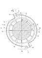
- An extraction chamber casing 6 that forms an extraction chamber 12 between the rotor casing 3 and the rotor casing 3 is provided on the outer peripheral side of the rotor casing 3.
- the extraction chamber 12 forms an annular space around the rotation axis Ar.
- a communication passage 13 is formed between the main flow path 4 and the extraction chamber 12, and the main flow path 4 and the extraction chamber 12 are communicated with each other.
- the extraction chamber casing 6 is formed with two extraction nozzles 14 for guiding the air A in the extraction chamber 12 to the outside.
- the bleed structure is constituted by the bleed chamber 12, the communication passage 13, and the plurality of bleed nozzles 14.
- the communication path 13 is a slit that is annularly formed around the rotation axis Ar and is cut radially outward, and is formed on the radially inner side of the extraction chamber 12.
- the opening on the main flow path 4 side of the communication path 13 is formed at a position between the stationary blade stage 9 and the moving blade stage 7 adjacent in the axial direction Da in the axial direction Da.
- the plurality of extraction nozzles 14 are arranged at equal intervals in the circumferential direction around the rotation axis Ar. That is, the extraction nozzles 14 of the present embodiment are arranged at intervals of 180 ° in the circumferential direction.
- the extraction nozzle 14 extends from the extraction chamber 12 outward in the radial direction.
- Each extraction nozzle 14 is connected to an extraction pipe 15 that guides the air A from the extraction nozzle 14 to a target location.
- the extraction pipe 15 is provided with a flow rate adjustment valve 16 for adjusting the flow rate of the extracted air.
- the extraction chamber 12 of the present embodiment includes a front side R1 in the rotation direction of the rotor 2 (downstream side in the air A flow direction) with respect to the extraction nozzle 14 and a rear side in the rotation direction of the rotor 2.
- the rear side R2 in the rotational direction is formed to have a larger flow path area as viewed from the circumferential direction.
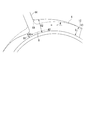
- the radial interval between the radially inner side surface 17 of the extraction chamber 12 casing and the radially outer side surface 18 of the rotor casing 3 is larger than the front side R1 in the rotational direction of the rotor 2 with respect to the extraction nozzle 14.
- the rear side R2 in the rotational direction is larger.
- the front side R1 in the rotational direction of the rotor 2 with respect to the bleed nozzle 14 is G
- the interval G1 is smaller than G
- the interval G2 on the rear side R2 in the rotational direction is larger than G than the extraction nozzle 14.
- the dimensions of the gap G1 and the gap G2 can be appropriately adjusted according to the flow rate of the air A in the extraction chamber 12 obtained by analysis by CFD.
- the distance between the bleed chamber 12 casing and the rotor casing 3 in the radial direction and the distance between the rear side R2 in the rotation direction with respect to the bleed nozzle 14 gradually increases toward the front side R1 in the rotation direction of the rotor 2. It is formed as follows. That is, the shape of the bleed chamber 12 casing on the rear side R2 in the rotational direction with respect to the bleed nozzle 14 is such that the flow path area gradually increases toward the front side R1 in the rotational direction. The distance between the bleed chamber 12 casing and the rotor casing 3 in the radial direction, and the distance between the front side R1 in the rotational direction with respect to the bleed nozzle 14 gradually decreases toward the front side R1 in the rotational direction of the rotor 2. It is formed as follows. That is, the shape of the bleed chamber 12 casing on the front side R1 in the rotational direction with respect to the bleed nozzle 14 is such that the flow passage area gradually decreases toward the front side R1 in the rotational direction.
- the inner peripheral surface of the extraction nozzle 14 and the radially outer surface 18 of the extraction chamber 12 are connected by a smooth curved surface 19 that is convex toward the air A flow path side.
- the connecting portion between the inner peripheral surface of the extraction nozzle 14 and the radially outer surface 18 of the extraction chamber casing 6 is chamfered into a convex round surface toward the air A flow path side. That is, no corners that are orthogonal to each other are formed between the inner peripheral surface of the bleed nozzle 14 and the radially outer surface 18 of the bleed chamber casing 6 and are connected smoothly.
- the air A that has flowed into the extraction chamber 12 via the communication passage 13 turns into a flow turning toward the front side R1 in the rotation direction of the rotor 2.
- the flow rate of the air A decreases in the region on the front side R1 in the rotation direction of the rotor 2 with respect to the extraction nozzle 14.
- the flow rate of the air A increases in the region on the rear side R2 in the rotation direction of the rotor 2 with respect to the extraction nozzle 14.
- the flow passage area is reduced corresponding to the decrease in the flow rate of the fluid on the front side R1 in the rotation direction of the rotor 2 with respect to the bleed nozzle 14, and the fluid on the rear side R2 in the rotation direction.
- the flow path area was increased corresponding to the increase in the flow rate.
- the uniformity of the flow rate of the air A can be further improved by making the shape of the bleed chamber 12 casing corresponding to the flow rate of the air A.
- the inner peripheral surface of the extraction nozzle 14 and the radially outer surface 18 of the extraction chamber 12 are connected by a smooth curved surface 19 having a convex shape toward the flow path side of the air A, thereby flowing through the extraction chamber 12.
- the separation of the air A can be suppressed, and the air A can be smoothly introduced into the extraction nozzle 14.
- the flow passage area on the rear side R2 in the rotational direction of the rotor 2 may be simply increased with respect to the extraction nozzle 14.
- the number of the extraction nozzles 14 does not ask
- the present invention is a compressor having a rotor that rotates about an axis and a casing that surrounds the rotor, and has a bleed structure for guiding a part of gas compressed by the rotor to the outside. It is applicable to.
Landscapes
- Engineering & Computer Science (AREA)
- Mechanical Engineering (AREA)
- General Engineering & Computer Science (AREA)
- Chemical & Material Sciences (AREA)
- Combustion & Propulsion (AREA)
- Life Sciences & Earth Sciences (AREA)
- Sustainable Development (AREA)
- Structures Of Non-Positive Displacement Pumps (AREA)
Priority Applications (4)
| Application Number | Priority Date | Filing Date | Title |
|---|---|---|---|
| US14/907,987 US10151320B2 (en) | 2013-10-17 | 2014-02-12 | Compressor and gas turbine |
| EP14853386.2A EP3059457B1 (en) | 2013-10-17 | 2014-02-12 | Compressor and gas turbine |
| CN201480041978.0A CN105452674B (zh) | 2013-10-17 | 2014-02-12 | 压缩机以及燃气轮机 |
| KR1020167001700A KR101805322B1 (ko) | 2013-10-17 | 2014-02-12 | 압축기 및 가스 터빈 |
Applications Claiming Priority (2)
| Application Number | Priority Date | Filing Date | Title |
|---|---|---|---|
| JP2013216484A JP6188069B2 (ja) | 2013-10-17 | 2013-10-17 | 圧縮機、及びガスタービン |
| JP2013-216484 | 2013-10-17 |
Publications (1)
| Publication Number | Publication Date |
|---|---|
| WO2015056456A1 true WO2015056456A1 (ja) | 2015-04-23 |
Family
ID=52827912
Family Applications (1)
| Application Number | Title | Priority Date | Filing Date |
|---|---|---|---|
| PCT/JP2014/053149 Ceased WO2015056456A1 (ja) | 2013-10-17 | 2014-02-12 | 圧縮機、及びガスタービン |
Country Status (6)
| Country | Link |
|---|---|
| US (1) | US10151320B2 (enExample) |
| EP (1) | EP3059457B1 (enExample) |
| JP (1) | JP6188069B2 (enExample) |
| KR (1) | KR101805322B1 (enExample) |
| CN (1) | CN105452674B (enExample) |
| WO (1) | WO2015056456A1 (enExample) |
Families Citing this family (6)
| Publication number | Priority date | Publication date | Assignee | Title |
|---|---|---|---|---|
| EP3131025A1 (en) * | 2015-08-14 | 2017-02-15 | Siemens Aktiengesellschaft | Method for the prediction of surge in a gas compressor |
| JP6689105B2 (ja) * | 2016-03-14 | 2020-04-28 | 三菱重工業株式会社 | 多段軸流圧縮機及びガスタービン |
| US10221773B2 (en) * | 2016-10-07 | 2019-03-05 | General Electric Company | Bleed valve assembly for a gas turbine engine |
| US11635030B2 (en) * | 2017-06-13 | 2023-04-25 | General Electric Company | Compressor bleed apparatus for a turbine engine |
| CN114508394B (zh) * | 2021-12-29 | 2023-11-10 | 东方电气集团东方汽轮机有限公司 | 一种透平抽汽腔室结构 |
| US20250052191A1 (en) * | 2023-08-07 | 2025-02-13 | Pratt & Whitney Canada Corp. | Compressor bleed offtake |
Citations (4)
| Publication number | Priority date | Publication date | Assignee | Title |
|---|---|---|---|---|
| JPH0763199A (ja) * | 1993-08-10 | 1995-03-07 | Abb Manag Ag | 軸流圧縮機から二次空気流を取り出す装置 |
| JP2012180749A (ja) | 2011-02-28 | 2012-09-20 | Mitsubishi Heavy Ind Ltd | 回転機械の抽気構造 |
| JP2013194513A (ja) * | 2012-03-15 | 2013-09-30 | Mitsubishi Heavy Ind Ltd | 吸気部ケーシング、及び圧縮機 |
| JP2013204545A (ja) * | 2012-03-29 | 2013-10-07 | Mitsubishi Heavy Ind Ltd | 圧縮機、及びガスタービン |
Family Cites Families (9)
| Publication number | Priority date | Publication date | Assignee | Title |
|---|---|---|---|---|
| JPS62126296A (ja) * | 1985-11-27 | 1987-06-08 | Hitachi Ltd | 軸流圧縮機の抽気装置 |
| GB2192229B (en) * | 1986-07-04 | 1990-05-02 | Rolls Royce Plc | A compressor and air bleed system |
| JPS6385299A (ja) * | 1986-09-29 | 1988-04-15 | Hitachi Ltd | 軸流圧縮機の抽気構造 |
| US5209633A (en) | 1990-11-19 | 1993-05-11 | General Electric Company | High pressure compressor flowpath bleed valve extraction slot |
| JPH0874603A (ja) * | 1994-09-05 | 1996-03-19 | Toshiba Corp | 圧縮機の流体抽出機構 |
| US6231301B1 (en) * | 1998-12-10 | 2001-05-15 | United Technologies Corporation | Casing treatment for a fluid compressor |
| JP5119676B2 (ja) * | 2007-02-14 | 2013-01-16 | 株式会社日立製作所 | 高湿分利用ガスタービン |
| JP2013072418A (ja) * | 2011-09-29 | 2013-04-22 | Mitsubishi Heavy Ind Ltd | 圧縮機 |
| JP6000142B2 (ja) | 2013-01-28 | 2016-09-28 | 三菱重工業株式会社 | 回転機械、及びこれを備えているガスタービン |
-
2013
- 2013-10-17 JP JP2013216484A patent/JP6188069B2/ja not_active Expired - Fee Related
-
2014
- 2014-02-12 EP EP14853386.2A patent/EP3059457B1/en active Active
- 2014-02-12 WO PCT/JP2014/053149 patent/WO2015056456A1/ja not_active Ceased
- 2014-02-12 CN CN201480041978.0A patent/CN105452674B/zh not_active Expired - Fee Related
- 2014-02-12 US US14/907,987 patent/US10151320B2/en not_active Expired - Fee Related
- 2014-02-12 KR KR1020167001700A patent/KR101805322B1/ko not_active Expired - Fee Related
Patent Citations (4)
| Publication number | Priority date | Publication date | Assignee | Title |
|---|---|---|---|---|
| JPH0763199A (ja) * | 1993-08-10 | 1995-03-07 | Abb Manag Ag | 軸流圧縮機から二次空気流を取り出す装置 |
| JP2012180749A (ja) | 2011-02-28 | 2012-09-20 | Mitsubishi Heavy Ind Ltd | 回転機械の抽気構造 |
| JP2013194513A (ja) * | 2012-03-15 | 2013-09-30 | Mitsubishi Heavy Ind Ltd | 吸気部ケーシング、及び圧縮機 |
| JP2013204545A (ja) * | 2012-03-29 | 2013-10-07 | Mitsubishi Heavy Ind Ltd | 圧縮機、及びガスタービン |
Also Published As
| Publication number | Publication date |
|---|---|
| EP3059457A1 (en) | 2016-08-24 |
| KR101805322B1 (ko) | 2017-12-05 |
| KR20160022897A (ko) | 2016-03-02 |
| CN105452674A (zh) | 2016-03-30 |
| JP2015078654A (ja) | 2015-04-23 |
| EP3059457B1 (en) | 2021-03-31 |
| US10151320B2 (en) | 2018-12-11 |
| CN105452674B (zh) | 2017-12-19 |
| EP3059457A4 (en) | 2017-06-21 |
| US20160169241A1 (en) | 2016-06-16 |
| JP6188069B2 (ja) | 2017-08-30 |
Similar Documents
| Publication | Publication Date | Title |
|---|---|---|
| JP6188069B2 (ja) | 圧縮機、及びガスタービン | |
| JP6134628B2 (ja) | 軸流式の圧縮機、及びガスタービン | |
| JP2015190354A5 (enExample) | ||
| CN105793577B (zh) | 离心压缩机的弯曲扩散通路部分 | |
| US10605266B2 (en) | Gas turbine engine | |
| JP6000142B2 (ja) | 回転機械、及びこれを備えているガスタービン | |
| KR102575119B1 (ko) | 부분 송입 터빈에 사용되는 손실 저감 장치 및 부분 송입 터빈 | |
| JP2014234729A (ja) | 遠心圧縮機及びガスタービンエンジン | |
| JP6037996B2 (ja) | 圧縮機、及びガスタービン | |
| US20160376900A1 (en) | Stator device for a continuous-flow machine with a housing appliance and multiple guide vanes | |
| WO2018110460A1 (ja) | トランジションダクト、タービン、及びガスタービンエンジン | |
| JP2015197052A5 (enExample) |
Legal Events
| Date | Code | Title | Description |
|---|---|---|---|
| WWE | Wipo information: entry into national phase |
Ref document number: 201480041978.0 Country of ref document: CN |
|
| 121 | Ep: the epo has been informed by wipo that ep was designated in this application |
Ref document number: 14853386 Country of ref document: EP Kind code of ref document: A1 |
|
| ENP | Entry into the national phase |
Ref document number: 20167001700 Country of ref document: KR Kind code of ref document: A |
|
| REEP | Request for entry into the european phase |
Ref document number: 2014853386 Country of ref document: EP |
|
| WWE | Wipo information: entry into national phase |
Ref document number: 2014853386 Country of ref document: EP |
|
| WWE | Wipo information: entry into national phase |
Ref document number: 14907987 Country of ref document: US |
|
| NENP | Non-entry into the national phase |
Ref country code: DE |