WO2015053151A1 - 緩衝器 - Google Patents
緩衝器 Download PDFInfo
- Publication number
- WO2015053151A1 WO2015053151A1 PCT/JP2014/076319 JP2014076319W WO2015053151A1 WO 2015053151 A1 WO2015053151 A1 WO 2015053151A1 JP 2014076319 W JP2014076319 W JP 2014076319W WO 2015053151 A1 WO2015053151 A1 WO 2015053151A1
- Authority
- WO
- WIPO (PCT)
- Prior art keywords
- outer cylinder
- shock absorber
- intermediate member
- sacrificial corrosion
- bump stopper
- Prior art date
- Legal status (The legal status is an assumption and is not a legal conclusion. Google has not performed a legal analysis and makes no representation as to the accuracy of the status listed.)
- Ceased
Links
Images



Classifications
-
- F—MECHANICAL ENGINEERING; LIGHTING; HEATING; WEAPONS; BLASTING
- F16—ENGINEERING ELEMENTS AND UNITS; GENERAL MEASURES FOR PRODUCING AND MAINTAINING EFFECTIVE FUNCTIONING OF MACHINES OR INSTALLATIONS; THERMAL INSULATION IN GENERAL
- F16F—SPRINGS; SHOCK-ABSORBERS; MEANS FOR DAMPING VIBRATION
- F16F9/00—Springs, vibration-dampers, shock-absorbers, or similarly-constructed movement-dampers using a fluid or the equivalent as damping medium
- F16F9/32—Details
- F16F9/38—Covers for protection or appearance
-
- B—PERFORMING OPERATIONS; TRANSPORTING
- B60—VEHICLES IN GENERAL
- B60G—VEHICLE SUSPENSION ARRANGEMENTS
- B60G15/00—Resilient suspensions characterised by arrangement, location or type of combined spring and vibration damper, e.g. telescopic type
- B60G15/02—Resilient suspensions characterised by arrangement, location or type of combined spring and vibration damper, e.g. telescopic type having mechanical spring
- B60G15/06—Resilient suspensions characterised by arrangement, location or type of combined spring and vibration damper, e.g. telescopic type having mechanical spring and fluid damper
-
- F—MECHANICAL ENGINEERING; LIGHTING; HEATING; WEAPONS; BLASTING
- F16—ENGINEERING ELEMENTS AND UNITS; GENERAL MEASURES FOR PRODUCING AND MAINTAINING EFFECTIVE FUNCTIONING OF MACHINES OR INSTALLATIONS; THERMAL INSULATION IN GENERAL
- F16F—SPRINGS; SHOCK-ABSORBERS; MEANS FOR DAMPING VIBRATION
- F16F13/00—Units comprising springs of the non-fluid type as well as vibration-dampers, shock-absorbers, or fluid springs
- F16F13/04—Units comprising springs of the non-fluid type as well as vibration-dampers, shock-absorbers, or fluid springs comprising both a plastics spring and a damper, e.g. a friction damper
- F16F13/06—Units comprising springs of the non-fluid type as well as vibration-dampers, shock-absorbers, or fluid springs comprising both a plastics spring and a damper, e.g. a friction damper the damper being a fluid damper, e.g. the plastics spring not forming a part of the wall of the fluid chamber of the damper
-
- F—MECHANICAL ENGINEERING; LIGHTING; HEATING; WEAPONS; BLASTING
- F16—ENGINEERING ELEMENTS AND UNITS; GENERAL MEASURES FOR PRODUCING AND MAINTAINING EFFECTIVE FUNCTIONING OF MACHINES OR INSTALLATIONS; THERMAL INSULATION IN GENERAL
- F16F—SPRINGS; SHOCK-ABSORBERS; MEANS FOR DAMPING VIBRATION
- F16F9/00—Springs, vibration-dampers, shock-absorbers, or similarly-constructed movement-dampers using a fluid or the equivalent as damping medium
- F16F9/32—Details
- F16F9/58—Stroke limiting stops, e.g. arranged on the piston rod outside the cylinder
-
- B—PERFORMING OPERATIONS; TRANSPORTING
- B60—VEHICLES IN GENERAL
- B60G—VEHICLE SUSPENSION ARRANGEMENTS
- B60G2202/00—Indexing codes relating to the type of spring, damper or actuator
- B60G2202/30—Spring/Damper and/or actuator Units
- B60G2202/32—The spring being in series with the damper and/or actuator
-
- B—PERFORMING OPERATIONS; TRANSPORTING
- B60—VEHICLES IN GENERAL
- B60G—VEHICLE SUSPENSION ARRANGEMENTS
- B60G2206/00—Indexing codes related to the manufacturing of suspensions: constructional features, the materials used, procedures or tools
- B60G2206/01—Constructional features of suspension elements, e.g. arms, dampers, springs
- B60G2206/40—Constructional features of dampers and/or springs
- B60G2206/41—Dampers
-
- F—MECHANICAL ENGINEERING; LIGHTING; HEATING; WEAPONS; BLASTING
- F16—ENGINEERING ELEMENTS AND UNITS; GENERAL MEASURES FOR PRODUCING AND MAINTAINING EFFECTIVE FUNCTIONING OF MACHINES OR INSTALLATIONS; THERMAL INSULATION IN GENERAL
- F16F—SPRINGS; SHOCK-ABSORBERS; MEANS FOR DAMPING VIBRATION
- F16F2230/00—Purpose; Design features
- F16F2230/0023—Purpose; Design features protective
-
- F—MECHANICAL ENGINEERING; LIGHTING; HEATING; WEAPONS; BLASTING
- F16—ENGINEERING ELEMENTS AND UNITS; GENERAL MEASURES FOR PRODUCING AND MAINTAINING EFFECTIVE FUNCTIONING OF MACHINES OR INSTALLATIONS; THERMAL INSULATION IN GENERAL
- F16F—SPRINGS; SHOCK-ABSORBERS; MEANS FOR DAMPING VIBRATION
- F16F9/00—Springs, vibration-dampers, shock-absorbers, or similarly-constructed movement-dampers using a fluid or the equivalent as damping medium
- F16F9/32—Details
- F16F9/3207—Constructional features
- F16F9/3235—Constructional features of cylinders
- F16F9/3242—Constructional features of cylinders of cylinder ends, e.g. caps
Definitions
- the present invention relates to a shock absorber.
- JP2001-50329A discloses a shock absorber provided with a bump cushion attached to the outer periphery of a rod protruding from an outer cylinder, and a synthetic resin bump stopper fitted to one end of the outer cylinder.
- this shock absorber the impact at the time of the maximum compression is absorbed by the bump cushion abutting against the bump stopper at the time of the maximum compression.
- the outer peripheral surface is painted for rust prevention.
- an unpainted portion is provided at the rod protruding side end of the outer cylinder in order to prevent the paint from entering the outer cylinder.
- the unpainted portion is covered with a bump stopper, but the synthetic resin bump stopper has no rust prevention effect. For this reason, corrosion progresses in the unpainted portion where the iron-based metal is exposed, and a corrosion product may ooze out to deteriorate the appearance or deteriorate the bump stopper.
- Such a phenomenon can occur even when the outer cylinder is formed of a metal other than iron, and even when a rust prevention measure is taken by a method other than painting, a rust prevention is provided at one end of the outer cylinder where the bump stopper is fitted. This can occur if it is difficult to process.
- a rust prevention measure is taken by a method other than painting
- labor costs and equipment costs increase, resulting in an increase in manufacturing costs. .
- the object of the present invention is to suppress corrosion of the exposed portion even if a portion where the metal is exposed is formed at one end of the outer cylinder to which the bump stopper is fitted.
- the shock absorber is a metal cylindrical outer cylinder, a rod inserted into the outer cylinder so as to be movable in the axial direction, and the rod protruding from the outer cylinder.
- a bump cushion that is attached to the outer periphery of the outer periphery, a bump stopper made of a synthetic resin that is formed in a cap shape and is fitted to one end in the axial direction of the outer cylinder, and the bump cushion abuts at the time of the most compression, And a sacrificial corrosion portion disposed between the stopper and the metal surface of the outer cylinder, wherein the sacrificial corrosion portion is provided with a shock absorber made of metal having a higher ionization tendency than the outer cylinder.
- FIG. 1 is a front view of a shock absorber according to an embodiment of the present invention, partially cut away.
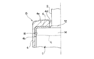
- FIG. 2 is an enlarged view of the main part of FIG.
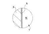
- FIG. 3 is an enlarged view of a portion III in FIG.
- FIG. 4 is an enlarged front view of a main part of a shock absorber according to another embodiment of the present invention, partially cut away.
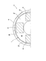
- FIG. 5 is a view showing a cross section taken along line VV of FIG.
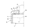
- FIG. 6 is an enlarged front view of a main part of a shock absorber according to another embodiment of the present invention, partially cut away.
- FIG. 7 is an enlarged view of a portion VII in FIG.
- a shock absorber D includes a metal cylindrical outer cylinder 1, a rod 2 that is movably inserted in the outer cylinder 1 in the axial direction, and an outer cylinder 1.
- a bump cushion 3 attached to the upper outer periphery of the protruding rod 2 and a synthetic resin bump stopper 4 formed in a cap shape and fitted to one end of the outer cylinder 1 in the axial direction are provided.
- the bump cushion 3 abuts against the bump stopper 4 at the time of the maximum compression of the shock absorber D in which the rod 2 enters the outer cylinder 1 to the maximum, so that the impact at the time of the maximum compression is absorbed and relaxed.
- the shock absorber D further includes a sacrificial corrosion portion 5 that is disposed between the outer cylinder 1 and the bump stopper 4 and contacts the metal surface M of the outer cylinder 1.
- the sacrificial corrosion portion 5 is a metal having a higher ionization tendency than the metal forming the outer cylinder 1.
- the shock absorber D is interposed between the vehicle body and the wheels. As shown in FIG. 1, the shock absorber D has an end portion of a rod 2 protruding from the outer cylinder 1 connected to the vehicle body side via a vehicle body side mount 20, and the outer cylinder 1 is fixed to the outer periphery thereof by welding. It is connected to the wheel side via a bracket 10. For this reason, when an impact due to road surface unevenness is input to the wheel, the rod 2 enters and exits the outer cylinder 1 and the shock absorber D expands and contracts.
- the shock absorber D according to this embodiment is an upright type in which the rod 2 is connected to the vehicle body side and the outer cylinder 1 is connected to the wheel side.
- the shock absorber D may be an inverted type in which the rod 2 is connected to the wheel side and the outer cylinder 1 is connected to the vehicle body side. Further, the shock absorber D may be used other than the automobile.
- the shock absorber D is coupled to the lower end of the rod 2 inserted into the outer cylinder 1 and slidably contacts the inner peripheral surface of the outer cylinder 1, and the piston is defined in the outer cylinder 1. And two chambers filled with the working fluid, a passage communicating these chambers, and a damping valve that provides resistance to the flow of the working fluid passing through the passage.
- the shock absorber D expands and contracts, the working fluid in one chamber to be reduced moves through the passage to the other chamber that expands.
- the shock absorber D generates a damping force due to the resistance of the damping valve when the working fluid passes through the passage.
- the working fluid various fluids such as liquids such as oil, water, and aqueous solutions, and gases can be used.
- the shock absorber D may be a so-called double-tube shock absorber provided with a cylinder in the outer cylinder 1 or a double rod shock absorber in which rods 2 protrude from both sides of the piston.
- the shock absorption relaxation at the time of the most compression is performed by converting the kinetic energy into elastic energy by the bump cushion 3 hitting the bump stopper 4 and elastically deforming when the shock absorber D is most compressed.
- the bump cushion 3 is made of synthetic resin, rubber, or the like. Instead of this, the bump cushion 3 may be made of a coil spring.
- the outer cylinder 1 to which the bump stopper 4 is fitted is formed of an iron-based metal, and a bracket 10 and a plate-shaped spring receiver 11 that supports the lower end of the suspension spring S are welded and fixed to the outer periphery. Since the outer cylinder 1 is formed of an iron-based metal, the bracket 10 and the spring receiver 11 can be easily welded. Then, after the welding operation, the outer cylinder 1 is coated with rust prevention.
- the painting method may be any method, but after painting, a portion where the metal surface M such as iron-based metal is exposed is formed at the upper end portion of the outer cylinder 1.
- the upper end of the outer cylinder 1 is crimped inward, and the seal 12 that closes the outer periphery of the rod 2 is pressed by the crimping portion 1a.
- the unpainted portion where the metal surface M is exposed is formed over the crimped portion 1a and the upper end of the cylindrical portion 1b connected to the crimped portion 1a.
- a dotted line L shown in FIGS. 1, 2, 4 and 6 indicates the boundary between the metal surface M and the unpainted coating surface on the outer periphery of the outer cylinder 1.
- the iron-based metal is a metal mainly composed of iron or pure iron.
- the unpainted portion of the outer cylinder 1 is covered with a bump stopper 4 fitted to the outer cylinder 1.
- a plurality of bump stoppers 4 are arranged in an annular top portion 4a, a cylindrical tube portion 4b standing on the outer peripheral edge of the top portion 4a, and extending in the axial direction on the inner periphery of the tube portion 4b at intervals in the circumferential direction.
- a rib-like cap-shaped member is formed in the top portion 4a.
- the press-fit load that is, the bonding strength between the bump stopper 4 and the outer cylinder 1 can be easily adjusted.
- the top part 4a, the cylinder part 4b, and the rib 4c are integrally formed of the same synthetic resin.
- the top part 4a, the cylinder part 4b, and the rib 4c may be formed by different synthetic resins, and may be integrated by insert molding.
- the top portion 4a collides with the bump cushion 3 at the time of maximum compression, it is preferably formed of a reinforced synthetic resin material in which glass fibers or carbon fibers are mixed in a synthetic resin in order to improve durability and strength.
- the number of ribs 4c may be two or more, and particularly three or more, the bump stopper 4 can be stably fixed to the outer cylinder 1.
- a metal intermediate member 6 is disposed so as to contact an unpainted portion where the metal surface M of the outer cylinder 1 is exposed.
- a sacrificial corrosion portion 5 is formed on the outer surface of the intermediate member 6 by plating.
- the intermediate member 6 is made of an iron-based metal, and is integrated with the bump stopper 4 by insert molding. Specifically, an intermediate member 6 plated with the sacrificial corrosion portion 5 is inserted into a mold for forming the bump stopper 4, and a synthetic resin material that is a material for the bump stopper 4 is poured into the mold.
- the bump stopper 4 As a result, simultaneously with the formation of the bump stopper 4, the bump stopper 4, the intermediate member 6, and the sacrificial corrosion portion 5 are integrated.
- the method of integrating is not limited to insert molding, and may be integrated by pressing the intermediate member 6 inside the bump stopper 4.
- the sacrificial corrosion portion 5 is made of a zinc-based metal and has a higher ionization tendency than the iron-based metal that forms the outer cylinder 1 and the intermediate member 6. For this reason, the sacrificial corrosion part 5 corrodes preferentially rather than the outer cylinder 1 and the intermediate member 6 which contact the sacrificial corrosion part 5, and suppresses that the outer cylinder 1 and the intermediate member 6 corrode.
- the sacrificial corrosion portion 5 does not need to be provided on the entire outer surface of the intermediate member 6, and may be provided only on a portion in contact with the metal surface M of the outer cylinder 1. Further, the method of forming the sacrificial corrosion portion 5 on the outer surface of the intermediate member 6 is not limited to plating, and may be another known coating method such as thermal spraying.
- the zinc-based metal is a metal mainly composed of zinc or pure zinc.
- the intermediate member 6 shown in FIG. 2 is formed in a cap shape in accordance with the bump stopper 4 and covers the metal surface M of the outer cylinder 1 which is an unpainted portion.
- the shape of the intermediate member 6 is not limited to the above shape, and the sacrificial corrosion portion 5 does not need to be in contact with the entire metal surface M of the outer cylinder 1.
- the intermediate member 6 on which the sacrificial corrosion portion 5 is plated may be composed of a plurality of parts as shown in FIGS. 4 and 5.
- the intermediate member 6 on which the sacrificial corrosion portion 5 is plated is a rectangular member, and is arranged at four locations with a gap in the circumferential direction. A part of the intermediate member 6 is embedded in the bump stopper 4 by insert molding, and the intermediate member 6 and the bump stopper 4 are integrated.
- the shape of the intermediate member 6 is not limited to a rectangular shape, and may be a geometrically simple shape such as a circle. The simpler the shape of the intermediate member 6 is, the cheaper and easier it is to form the intermediate member 6.
- the number of intermediate members 6 is not limited to four, and may be increased or decreased as appropriate in consideration of the rust prevention effect of the metal surface M.
- the method of attaching the sacrificial corrosion portion 5 is not limited to the above configuration.
- the bump stopper 4 and the intermediate member 6 plated with the sacrificial corrosion portion 5 are separated.
- the intermediate member 6 may be held between the bump stopper 4 and the outer cylinder 1.
- the attachment work to the shock absorber D is facilitated by forming the intermediate member 6 in an annular shape.
- a commercially available galvanized washer can be used, and the shock absorber D can be manufactured at a low cost.
- the outer cylinder 1 and the intermediate member 6 are made of iron-based metal, and the sacrificial corrosion portion 5 is made of zinc-based metal.
- the sacrificial corrosion part 5 is a zinc-based metal, even if it corrodes, the corrosion part only turns white. For this reason, even if the sacrificial corrosion part 5 corrodes, it does not turn reddish brown or the corrosion product oozes out and deteriorates the appearance as when iron corrodes.
- the outer cylinder 1 consists of an iron-type metal, the outer cylinder 1 can be formed cheaply and easily. In particular, when peripheral parts such as the bracket 10 and the spring receiver 11 are welded to the outer cylinder 1, the weldability between the outer cylinder 1 made of iron-based metal and the peripheral parts can be improved. Further, since the intermediate member 6 is made of an iron-based metal, the intermediate member 6 can be easily formed at low cost, and galvanization as the sacrificial corrosion portion 5 can be easily performed.
- the metal which forms the outer cylinder 1, the intermediate member 6, and the sacrificial corrosion part 5 forms the sacrificial corrosion part 5 rather than the above limitation rather than the ionization tendency of the metal which forms the outer cylinder 1 and the intermediate member 6. It is sufficient if the ionization tendency of the metal is high. If the ionization tendency is lower than that of the sacrificial corrosion portion 5, the outer cylinder 1 and the intermediate member 6 may be formed of different materials.
- the intermediate member 6 on which the sacrificial corrosion portion 5 is formed is integrated with the bump stopper 4 by insert molding.
- the intermediate member 6 when the bump stopper 4 is formed, the intermediate member 6 is attached to the bump stopper 4 so that the bump stopper 4 and the sacrificial corrosion portion 5 are integrated. For this reason, the sacrificial corrosion portion 5 is not forgotten to be interposed between the outer cylinder 1 and the bump stopper 4, and corrosion of the unpainted portion of the outer cylinder 1 can be reliably suppressed by the sacrificial corrosion portion 5. Further, since the intermediate member 6 plated with the sacrificial corrosion portion 5 is integrated with the bump stopper 4 by insert molding, the intermediate member 6 may be composed of a plurality of parts, and the shape of the intermediate member 6 is free. Can be set to
- the intermediate member 6 on which the sacrificial corrosion portion 5 is formed is sandwiched and held between the bump stopper 4 and the outer cylinder 1.
- This configuration facilitates the work of attaching the intermediate member 6 to the shock absorber D. Further, if a commercially available galvanized washer or the like is used as the intermediate member 6, the shock absorber D can be manufactured at low cost.
- the shock absorber D includes an intermediate member 6 interposed between the outer cylinder 1 and the bump stopper 4, and a sacrificial corrosion portion 5 is formed on the surface of the intermediate member 6.
- the sacrificial corrosion portion 5 is formed on the surface of the intermediate member 6, the amount of metal used to form the sacrificial corrosion portion 5 can be suppressed, and the shock absorber D can be manufactured at low cost.
- a member formed of a zinc-based metal may be held between the outer cylinder 1 and the bump stopper 4 or may be attached to the metal surface M of the outer cylinder 1. Good. In this case, the intermediate member 6 can be abolished.
- the shock absorber D is disposed between the outer cylinder 1 and the bump stopper 4 and includes a sacrificial corrosion portion 5 that comes into contact with the metal surface M of the outer cylinder 1. It consists of a metal having a higher ionization tendency than the metal to be formed.
- the sacrificial corrosion portion 5 that contacts the metal surface M of the outer cylinder 1 corrodes preferentially over the unpainted portion of the outer cylinder 1, so that corrosion of the unpainted portion can be suppressed. That is, even if the end portion of the outer cylinder 1 to which the bump stopper 4 is fitted cannot be subjected to the same rust-proofing treatment as the other portions, and the portion where the metal is exposed is formed, the sacrificial corrosion portion 5 is provided. Corrosion of the part can be easily suppressed.
Landscapes
- Engineering & Computer Science (AREA)
- General Engineering & Computer Science (AREA)
- Mechanical Engineering (AREA)
- Fluid-Damping Devices (AREA)
- Springs (AREA)
- Prevention Of Electric Corrosion (AREA)
- Refuge Islands, Traffic Blockers, Or Guard Fence (AREA)
Abstract
Description
Claims (5)
- 緩衝器であって、
金属製の筒状の外筒と、
前記外筒内に軸方向に移動可能に挿入されるロッドと、
前記外筒から突出する前記ロッドの外周に取り付けられるバンプクッションと、
キャップ状に形成されて前記外筒の軸方向の一端に嵌合され、最圧縮時に前記バンプクッションが突き当たる合成樹脂製のバンプストッパと、
前記外筒と前記バンプストッパとの間に配置され、前記外筒の金属面に接触する犠牲腐食部と、を備え、
前記犠牲腐食部は、前記外筒よりもイオン化傾向が高い金属からなる緩衝器。 - 請求項1に記載の緩衝器であって、
前記外筒と前記バンプストッパとの間に介装される中間部材をさらに備え、
前記中間部材の表面には、前記犠牲腐食部が形成される緩衝器。 - 請求項2に記載の緩衝器であって、
前記犠牲腐食部が形成された前記中間部材は、インサート成形により、前記バンプストッパと一体化される緩衝器。 - 請求項2に記載の緩衝器であって、
前記犠牲腐食部が形成された前記中間部材は、前記バンプストッパと前記外筒との間に挟まれて保持される緩衝器。 - 請求項2に記載の緩衝器であって、
前記外筒と前記中間部材は、鉄系金属からなり、前記犠牲腐食部は、亜鉛系金属からなる緩衝器。
Priority Applications (3)
| Application Number | Priority Date | Filing Date | Title |
|---|---|---|---|
| DE112014004630.2T DE112014004630T5 (de) | 2013-10-08 | 2014-10-01 | Stossdämpfer |
| CN201480054938.XA CN105637253B (zh) | 2013-10-08 | 2014-10-01 | 缓冲器 |
| US14/917,036 US9777791B2 (en) | 2013-10-08 | 2014-10-01 | Shock absorber |
Applications Claiming Priority (2)
| Application Number | Priority Date | Filing Date | Title |
|---|---|---|---|
| JP2013-210641 | 2013-10-08 | ||
| JP2013210641A JP5799069B2 (ja) | 2013-10-08 | 2013-10-08 | 緩衝器 |
Publications (1)
| Publication Number | Publication Date |
|---|---|
| WO2015053151A1 true WO2015053151A1 (ja) | 2015-04-16 |
Family
ID=52812967
Family Applications (1)
| Application Number | Title | Priority Date | Filing Date |
|---|---|---|---|
| PCT/JP2014/076319 Ceased WO2015053151A1 (ja) | 2013-10-08 | 2014-10-01 | 緩衝器 |
Country Status (5)
| Country | Link |
|---|---|
| US (1) | US9777791B2 (ja) |
| JP (1) | JP5799069B2 (ja) |
| CN (1) | CN105637253B (ja) |
| DE (1) | DE112014004630T5 (ja) |
| WO (1) | WO2015053151A1 (ja) |
Cited By (1)
| Publication number | Priority date | Publication date | Assignee | Title |
|---|---|---|---|---|
| WO2020045327A1 (ja) * | 2018-08-27 | 2020-03-05 | 日本精機株式会社 | ストロークセンサ |
Families Citing this family (6)
| Publication number | Priority date | Publication date | Assignee | Title |
|---|---|---|---|---|
| JP6616672B2 (ja) * | 2015-11-20 | 2019-12-04 | Kyb株式会社 | バンプストッパ、及び緩衝器 |
| JP6817731B2 (ja) * | 2016-06-30 | 2021-01-20 | Kyb株式会社 | 筒部材及び緩衝器 |
| JP6428821B2 (ja) * | 2017-03-27 | 2018-11-28 | マツダ株式会社 | 車両の後部車体構造 |
| DE102017206486A1 (de) * | 2017-04-18 | 2018-10-18 | Zf Friedrichshafen Ag | Schwingungsdämpfer |
| DE102019117200A1 (de) * | 2018-07-04 | 2020-01-09 | Fanuc Corporation | Horizontal-gelenkroboter |
| JP7502976B2 (ja) * | 2020-11-25 | 2024-06-19 | カヤバ株式会社 | 緩衝器 |
Citations (5)
| Publication number | Priority date | Publication date | Assignee | Title |
|---|---|---|---|---|
| JPS57107608U (ja) * | 1980-12-24 | 1982-07-02 | ||
| JPS6177505A (ja) * | 1984-09-26 | 1986-04-21 | Kinugawa Rubber Ind Co Ltd | リバウンドバンパ |
| JPH03277841A (ja) * | 1990-03-26 | 1991-12-09 | Atsugi Unisia Corp | 緩衝器 |
| JP2001050329A (ja) * | 1999-08-06 | 2001-02-23 | Toyoda Gosei Co Ltd | ショックアブソーバー用キャップ |
| JP2006170386A (ja) * | 2004-12-17 | 2006-06-29 | Tokai Rubber Ind Ltd | サスペンション装置用のバウンドストッパ |
Family Cites Families (5)
| Publication number | Priority date | Publication date | Assignee | Title |
|---|---|---|---|---|
| CN1641243A (zh) * | 2003-12-04 | 2005-07-20 | 佐藤孝典 | 螺栓连接构造和阻尼器构造 |
| JP5206965B2 (ja) * | 2008-01-31 | 2013-06-12 | 日立オートモティブシステムズ株式会社 | 流体圧緩衝器 |
| DE102008062902B4 (de) * | 2008-12-23 | 2022-01-27 | Volkswagen Ag | Schwingungsdämpfer und Schutzkappe zur Befestigung an einem Behälterrohr eines Schwingsdämpfers |
| CN201991990U (zh) * | 2011-03-21 | 2011-09-28 | 浙江吉利汽车研究院有限公司 | 一种汽车减震器防尘罩的连接结构 |
| JP6435741B2 (ja) * | 2014-09-22 | 2018-12-12 | トヨタ自動車株式会社 | バンプストッパキャップ |
-
2013
- 2013-10-08 JP JP2013210641A patent/JP5799069B2/ja active Active
-
2014
- 2014-10-01 DE DE112014004630.2T patent/DE112014004630T5/de not_active Withdrawn
- 2014-10-01 WO PCT/JP2014/076319 patent/WO2015053151A1/ja not_active Ceased
- 2014-10-01 CN CN201480054938.XA patent/CN105637253B/zh not_active Expired - Fee Related
- 2014-10-01 US US14/917,036 patent/US9777791B2/en not_active Expired - Fee Related
Patent Citations (5)
| Publication number | Priority date | Publication date | Assignee | Title |
|---|---|---|---|---|
| JPS57107608U (ja) * | 1980-12-24 | 1982-07-02 | ||
| JPS6177505A (ja) * | 1984-09-26 | 1986-04-21 | Kinugawa Rubber Ind Co Ltd | リバウンドバンパ |
| JPH03277841A (ja) * | 1990-03-26 | 1991-12-09 | Atsugi Unisia Corp | 緩衝器 |
| JP2001050329A (ja) * | 1999-08-06 | 2001-02-23 | Toyoda Gosei Co Ltd | ショックアブソーバー用キャップ |
| JP2006170386A (ja) * | 2004-12-17 | 2006-06-29 | Tokai Rubber Ind Ltd | サスペンション装置用のバウンドストッパ |
Cited By (3)
| Publication number | Priority date | Publication date | Assignee | Title |
|---|---|---|---|---|
| WO2020045327A1 (ja) * | 2018-08-27 | 2020-03-05 | 日本精機株式会社 | ストロークセンサ |
| JPWO2020045327A1 (ja) * | 2018-08-27 | 2021-08-12 | 日本精機株式会社 | ストロークセンサ |
| JP7310825B2 (ja) | 2018-08-27 | 2023-07-19 | 日本精機株式会社 | ストロークセンサ |
Also Published As
| Publication number | Publication date |
|---|---|
| US9777791B2 (en) | 2017-10-03 |
| CN105637253B (zh) | 2018-09-07 |
| DE112014004630T5 (de) | 2016-10-13 |
| JP2015075147A (ja) | 2015-04-20 |
| JP5799069B2 (ja) | 2015-10-21 |
| US20160215848A1 (en) | 2016-07-28 |
| CN105637253A (zh) | 2016-06-01 |
Similar Documents
| Publication | Publication Date | Title |
|---|---|---|
| WO2015053151A1 (ja) | 緩衝器 | |
| US10125840B2 (en) | Air spring hybrid piston assembly | |
| US9644703B2 (en) | Shock absorber | |
| US20150247549A1 (en) | Cylinder apparatus | |
| JP6420602B2 (ja) | 緩衝器 | |
| US20130220751A1 (en) | Dust lip for shock absorber | |
| US9556924B2 (en) | Shock absorber | |
| JP2015075147A5 (ja) | ||
| US20170261061A1 (en) | Shock absorber | |
| US8561768B2 (en) | Vehicle damper and method | |
| US4653618A (en) | Twin tube shock absorber gas seal | |
| KR102138416B1 (ko) | 실린더 장치 | |
| JP6378963B2 (ja) | 緩衝器 | |
| CN205877054U (zh) | 用于保护减震器储油筒的装置、减震器和车辆 | |
| KR102221835B1 (ko) | 차량 현가장치의 리어 어퍼암 | |
| KR100837236B1 (ko) | 쇽 업소버 | |
| KR100803154B1 (ko) | 쇽 업소버의 씰링 구조 | |
| JP4883279B2 (ja) | シリンダ装置 | |
| KR100775515B1 (ko) | 쇽업소버의 오일씰 | |
| KR100837235B1 (ko) | 쇽업소버의 캡 | |
| KR101375802B1 (ko) | 로드 가이드용 마찰식 댐핑 부재 | |
| JP5088823B2 (ja) | 金属ベローズ式アキュムレータ | |
| CN204140752U (zh) | 一种新型多功能汽车减震器 | |
| KR101374879B1 (ko) | 다이나믹 댐핑 구조 | |
| JP2024154066A (ja) | 緩衝器 |
Legal Events
| Date | Code | Title | Description |
|---|---|---|---|
| 121 | Ep: the epo has been informed by wipo that ep was designated in this application |
Ref document number: 14852191 Country of ref document: EP Kind code of ref document: A1 |
|
| WWE | Wipo information: entry into national phase |
Ref document number: 14917036 Country of ref document: US |
|
| WWE | Wipo information: entry into national phase |
Ref document number: 112014004630 Country of ref document: DE Ref document number: 1120140046302 Country of ref document: DE |
|
| 122 | Ep: pct application non-entry in european phase |
Ref document number: 14852191 Country of ref document: EP Kind code of ref document: A1 |