WO2015046439A1 - プリズムシート、面光源装置、映像源ユニット、及び液晶表示装置 - Google Patents
プリズムシート、面光源装置、映像源ユニット、及び液晶表示装置 Download PDFInfo
- Publication number
- WO2015046439A1 WO2015046439A1 PCT/JP2014/075657 JP2014075657W WO2015046439A1 WO 2015046439 A1 WO2015046439 A1 WO 2015046439A1 JP 2014075657 W JP2014075657 W JP 2014075657W WO 2015046439 A1 WO2015046439 A1 WO 2015046439A1
- Authority
- WO
- WIPO (PCT)
- Prior art keywords
- light
- unit
- prism
- sheet
- main body
- Prior art date
- Legal status (The legal status is an assumption and is not a legal conclusion. Google has not performed a legal analysis and makes no representation as to the accuracy of the status listed.)
- Ceased
Links
Images




Classifications
-
- G—PHYSICS
- G02—OPTICS
- G02B—OPTICAL ELEMENTS, SYSTEMS OR APPARATUS
- G02B6/00—Light guides; Structural details of arrangements comprising light guides and other optical elements, e.g. couplings
- G02B6/0001—Light guides; Structural details of arrangements comprising light guides and other optical elements, e.g. couplings specially adapted for lighting devices or systems
- G02B6/0011—Light guides; Structural details of arrangements comprising light guides and other optical elements, e.g. couplings specially adapted for lighting devices or systems the light guides being planar or of plate-like form
- G02B6/0033—Means for improving the coupling-out of light from the light guide
- G02B6/005—Means for improving the coupling-out of light from the light guide provided by one optical element, or plurality thereof, placed on the light output side of the light guide
- G02B6/0053—Prismatic sheet or layer; Brightness enhancement element, sheet or layer
-
- G—PHYSICS
- G02—OPTICS
- G02B—OPTICAL ELEMENTS, SYSTEMS OR APPARATUS
- G02B5/00—Optical elements other than lenses
- G02B5/02—Diffusing elements; Afocal elements
- G02B5/0205—Diffusing elements; Afocal elements characterised by the diffusing properties
- G02B5/021—Diffusing elements; Afocal elements characterised by the diffusing properties the diffusion taking place at the element's surface, e.g. by means of surface roughening or microprismatic structures
- G02B5/0231—Diffusing elements; Afocal elements characterised by the diffusing properties the diffusion taking place at the element's surface, e.g. by means of surface roughening or microprismatic structures the surface having microprismatic or micropyramidal shape
-
- G—PHYSICS
- G02—OPTICS
- G02B—OPTICAL ELEMENTS, SYSTEMS OR APPARATUS
- G02B5/00—Optical elements other than lenses
- G02B5/02—Diffusing elements; Afocal elements
- G02B5/0205—Diffusing elements; Afocal elements characterised by the diffusing properties
- G02B5/0236—Diffusing elements; Afocal elements characterised by the diffusing properties the diffusion taking place within the volume of the element
- G02B5/0242—Diffusing elements; Afocal elements characterised by the diffusing properties the diffusion taking place within the volume of the element by means of dispersed particles
-
- G—PHYSICS
- G02—OPTICS
- G02B—OPTICAL ELEMENTS, SYSTEMS OR APPARATUS
- G02B5/00—Optical elements other than lenses
- G02B5/04—Prisms
- G02B5/045—Prism arrays
-
- G—PHYSICS
- G02—OPTICS
- G02B—OPTICAL ELEMENTS, SYSTEMS OR APPARATUS
- G02B6/00—Light guides; Structural details of arrangements comprising light guides and other optical elements, e.g. couplings
- G02B6/0001—Light guides; Structural details of arrangements comprising light guides and other optical elements, e.g. couplings specially adapted for lighting devices or systems
- G02B6/0011—Light guides; Structural details of arrangements comprising light guides and other optical elements, e.g. couplings specially adapted for lighting devices or systems the light guides being planar or of plate-like form
- G02B6/0033—Means for improving the coupling-out of light from the light guide
- G02B6/0035—Means for improving the coupling-out of light from the light guide provided on the surface of the light guide or in the bulk of it
- G02B6/0038—Linear indentations or grooves, e.g. arc-shaped grooves or meandering grooves, extending over the full length or width of the light guide
-
- G—PHYSICS
- G02—OPTICS
- G02F—OPTICAL DEVICES OR ARRANGEMENTS FOR THE CONTROL OF LIGHT BY MODIFICATION OF THE OPTICAL PROPERTIES OF THE MEDIA OF THE ELEMENTS INVOLVED THEREIN; NON-LINEAR OPTICS; FREQUENCY-CHANGING OF LIGHT; OPTICAL LOGIC ELEMENTS; OPTICAL ANALOGUE/DIGITAL CONVERTERS
- G02F1/00—Devices or arrangements for the control of the intensity, colour, phase, polarisation or direction of light arriving from an independent light source, e.g. switching, gating or modulating; Non-linear optics
- G02F1/01—Devices or arrangements for the control of the intensity, colour, phase, polarisation or direction of light arriving from an independent light source, e.g. switching, gating or modulating; Non-linear optics for the control of the intensity, phase, polarisation or colour
- G02F1/13—Devices or arrangements for the control of the intensity, colour, phase, polarisation or direction of light arriving from an independent light source, e.g. switching, gating or modulating; Non-linear optics for the control of the intensity, phase, polarisation or colour based on liquid crystals, e.g. single liquid crystal display cells
- G02F1/133—Constructional arrangements; Operation of liquid crystal cells; Circuit arrangements
- G02F1/1333—Constructional arrangements; Manufacturing methods
- G02F1/133308—Support structures for LCD panels, e.g. frames or bezels
-
- G—PHYSICS
- G02—OPTICS
- G02F—OPTICAL DEVICES OR ARRANGEMENTS FOR THE CONTROL OF LIGHT BY MODIFICATION OF THE OPTICAL PROPERTIES OF THE MEDIA OF THE ELEMENTS INVOLVED THEREIN; NON-LINEAR OPTICS; FREQUENCY-CHANGING OF LIGHT; OPTICAL LOGIC ELEMENTS; OPTICAL ANALOGUE/DIGITAL CONVERTERS
- G02F1/00—Devices or arrangements for the control of the intensity, colour, phase, polarisation or direction of light arriving from an independent light source, e.g. switching, gating or modulating; Non-linear optics
- G02F1/01—Devices or arrangements for the control of the intensity, colour, phase, polarisation or direction of light arriving from an independent light source, e.g. switching, gating or modulating; Non-linear optics for the control of the intensity, phase, polarisation or colour
- G02F1/13—Devices or arrangements for the control of the intensity, colour, phase, polarisation or direction of light arriving from an independent light source, e.g. switching, gating or modulating; Non-linear optics for the control of the intensity, phase, polarisation or colour based on liquid crystals, e.g. single liquid crystal display cells
- G02F1/133—Constructional arrangements; Operation of liquid crystal cells; Circuit arrangements
- G02F1/1333—Constructional arrangements; Manufacturing methods
- G02F1/1335—Structural association of cells with optical devices, e.g. polarisers or reflectors
- G02F1/1336—Illuminating devices
- G02F1/133615—Edge-illuminating devices, i.e. illuminating from the side
-
- G—PHYSICS
- G02—OPTICS
- G02B—OPTICAL ELEMENTS, SYSTEMS OR APPARATUS
- G02B6/00—Light guides; Structural details of arrangements comprising light guides and other optical elements, e.g. couplings
- G02B6/0001—Light guides; Structural details of arrangements comprising light guides and other optical elements, e.g. couplings specially adapted for lighting devices or systems
- G02B6/0011—Light guides; Structural details of arrangements comprising light guides and other optical elements, e.g. couplings specially adapted for lighting devices or systems the light guides being planar or of plate-like form
- G02B6/0033—Means for improving the coupling-out of light from the light guide
- G02B6/0035—Means for improving the coupling-out of light from the light guide provided on the surface of the light guide or in the bulk of it
- G02B6/004—Scattering dots or dot-like elements, e.g. microbeads, scattering particles, nanoparticles
- G02B6/0041—Scattering dots or dot-like elements, e.g. microbeads, scattering particles, nanoparticles provided in the bulk of the light guide
Definitions
- the present invention relates to a prism sheet provided in a surface light source device that functions as illumination of a display device, a surface light source device using the prism sheet, an image source unit, and a liquid crystal display device.
- a liquid crystal display device such as a liquid crystal television provides an image to an observer by using a surface light source device (backlight) disposed on the back side of the liquid crystal panel as illumination for a liquid crystal panel including image information.
- a surface light source device backlight
- the surface light source device guides the light emitted from the light source in the light guide direction, spreads the light in a planar shape, and emits the light, and deflects the light in a predetermined direction ( The light is changed to a predetermined traveling direction.)
- the prism sheet (lens sheet) is included.
- the prism sheet is disposed between the light exit surface side of the light guide plate and the liquid crystal panel, and changes the direction of light from the light guide plate so that light can efficiently pass through the liquid crystal panel.
- the prism sheet has a plurality of unit prisms arranged on the light guide plate side, that is, on the light incident side.
- a layer containing a light diffusing agent is laminated on the light exit surface side where the unit prism is not arranged in the prism sheet.
- Patent Document 1 describes that by satisfying a predetermined condition, the concealability is maintained and the viewing angle is widened while preventing glare.
- Patent Document 1 in order to prevent glare in such a conventional surface light source device, only a solution for giving a high haze to a diffusible layer has been studied (patent) (Description of claim 1 in Document 1).
- Patent Document 1 there is a need for improvement from the viewpoint of efficiently using the light from the surface light source device because it causes a loss of light due to the diffusion of light in a direction that is not required in the optical member having such a high haze.
- glare is defined as follows.
- glare is also called scintillation, and when the screen of a display device is turned on, a fine grainy luminance unevenness appears on the screen, and when the viewing angle is changed, the position of the granular luminance unevenness appears to change. is there.
- an object of the present invention is to provide a prism sheet that suppresses the occurrence of glare and further reduces light loss.
- a surface light source device, an image source unit, and a liquid crystal display device using the same are provided.
- the present invention is a prism sheet that changes the direction of incident light and emits the light, and has a sheet-like main body portion having light transparency, and a plurality of convex unit prisms disposed on one surface side of the main body portion. Are arranged in a direction along the sheet surface, and a light diffusion layer disposed on the other surface side of the main body, and the unit prism has an apex angle of 80 ° or less at the convex tip.
- the pitch of the plurality of unit prisms is P ( ⁇ m) and the surface roughness of the light diffusion layer is Ra ( ⁇ m)
- Ra ⁇ ⁇ 0.0296 ⁇ P + 1.944 This is a prism sheet.
- the present invention also provides a prism sheet that emits light with its direction changed, and is disposed on one surface side of the sheet-like main body portion and the main body portion, and has a plurality of convex shapes.
- the unit prism includes unit prism portions arranged in a direction along the sheet surface, and a light diffusion layer disposed on the other surface side of the main body portion, and the unit prism sandwiches the apex serving as a convex tip.
- the one side is a light incident surface
- the other side is a reflection surface
- the reflection surface is composed of three surfaces having different inclination angles.
- the pitch of the plurality of unit prisms is P ( ⁇ m), and the surface roughness of the light diffusion layer is Ra ( ⁇ m). ), P is 10 ⁇ m or more, Ra is 0.035 ⁇ m or more, and Ra ⁇ ⁇ 0.0263 ⁇ P + 2.0537 This is a prism sheet.
- the present invention also provides a prism sheet that emits light with its direction changed, and is disposed on one surface side of the sheet-like main body portion and the main body portion, and has a plurality of convex shapes.
- the unit prism includes a unit prism portion arranged in a direction along the sheet surface, and a light diffusion layer disposed on the other surface side of the main body portion.
- the unit prism has a symmetrical shape and a convex tip.
- the pitch of the plurality of unit prisms is P ( ⁇ m)
- the surface roughness of the light diffusion layer is Ra ( ⁇ m), Ra ⁇ ⁇ 0.0208 ⁇ P + 2.0223 This is a prism sheet.
- the present invention is a surface light source device including a light source, a light guide plate that guides light emitted from the light source, and the prism sheet according to any one of the above that is disposed on a light output surface side of the light guide plate.
- the present invention is an image source unit comprising the above surface light source device and a liquid crystal panel disposed on the light output side of the surface light source device.
- the present invention is a liquid crystal display device comprising the above video source unit and a housing containing the video source unit.
- the present invention it is possible to suppress the occurrence of glare even if the haze of the light diffusion layer is lowered in order to suppress a decrease in luminance and light loss.
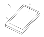
- FIG. 1 is an external perspective view of a liquid crystal display device 1.
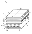
- FIG. It is a disassembled perspective view explaining the image source unit 10 concerning a 1st form.
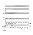
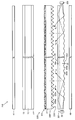
- FIG. 3 is an exploded view showing one cross section (cross section taken along III-III in FIG. 2) of the video source unit 10;
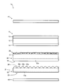
- FIG. 4 is an exploded view showing another cross section (cross section taken along the line IV-IV in FIG. 2) of the video source unit 10; It is the figure which expanded a part of light-guide plate 21.
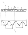
- FIG. 3 is an enlarged view of a part of the prism sheet 30.
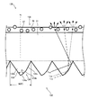
- FIG. It is the figure explaining a 2nd form, and is the figure which expanded some prism sheets. It is a figure explaining the shape of the unit prism 132a.
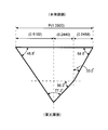
- FIG. 3 is a diagram illustrating the shape of one unit prism used in Example 1. It is a figure explaining the shape of the other unit prism used for Example 1.
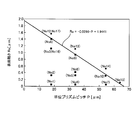
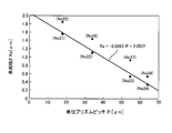
- FIG. 6 is a graph showing the relationship between the pitch P of the unit prisms of Example 1 and the surface roughness Ra of the light diffusion layer. It is a graph showing the relationship between the pitch P of the unit prism of Example 2, and the surface roughness Ra of a light-diffusion layer. It is a figure explaining the shape of one unit prism used for Example 3.
- FIG. It is a figure explaining the shape of the other unit prism used for Example 3.
- FIG. It is a graph showing the relationship between the pitch P of the unit prism of Example 3, and the surface roughness Ra of a light-diffusion layer.
- FIG. 1 is an external perspective view of a liquid crystal display device 1 according to the first embodiment
- FIG. 2 is an exploded perspective view conceptually showing an image source unit 10 included in the liquid crystal display device 1.
- the liquid crystal display device 1 includes a housing 2, and a video source unit 10 is built inside the housing 2.
- the housing 2 forms an outer shell of the liquid crystal display device 1 and accommodates most of the members constituting the liquid crystal display device 1 inside.
- the housing 2 has an opening, and a so-called screen portion of the image source unit 10 is exposed from the opening so that an image or the like can be visually recognized.
- the liquid crystal display device 1 includes various known constituent members for functioning as a liquid crystal display device.
- the liquid crystal display device 1 has an image source unit 10 and is observed after white light source light emitted from the surface light source device 20 included in the image source unit 10 passes through the liquid crystal panel 15 to obtain image information. Provided to the party.
- the video source unit 10 includes a liquid crystal panel 15, a surface light source device 20, and a functional sheet 41 as can be seen from FIG.
- the upper side of the drawing is the observer side.
- the liquid crystal panel 15 includes an upper polarizing plate 13 disposed on the viewer side, a lower polarizing plate 14 disposed on the surface light source device 20 side, and a liquid crystal disposed between the upper polarizing plate 13 and the lower polarizing plate 14. It has a layer 12.
- the upper polarizing plate 13 and the lower polarizing plate 14 decompose incident light into two orthogonal polarization components (P wave and S wave), and a polarization component (for example, P wave) in one direction (direction parallel to the transmission axis). ) And absorbs a polarization component (for example, S wave) in the other direction (direction parallel to the absorption axis) perpendicular to the one direction.
- the liquid crystal layer 12 can be applied with an electric field for each region where one pixel is formed. Then, the orientation of the liquid crystal layer 12 applied with an electric field changes.
- a polarization component for example, P wave
- P wave in a specific direction that has passed through the lower polarizing plate 14 disposed on the surface light source device 20 side (that is, the light incident side) changes its polarization direction when passing through the liquid crystal layer 12 to which an electric field is applied. While rotating 90 °, the polarization direction is maintained when passing through the liquid crystal layer 12 to which no electric field is applied.
- the polarization component (P wave) in a specific direction transmitted through the lower polarizing plate 14 is further transmitted through the upper polarizing plate 13 disposed on the light output side of the lower polarizing plate 14. It is possible to control whether it is absorbed or blocked by the upper polarizing plate 13.
- the liquid crystal panel 15 is configured to be able to express an image by controlling transmission or blocking of light from the surface light source device 20 for each pixel.
- liquid crystal panels There are various types of liquid crystal panels, but they can be used without any particular limitation.
- FIG. 3 is a cross-sectional view of the image source unit 10 in the thickness direction (vertical direction in FIG. 2) along the line III-III in FIG. 2, and FIG. 4 is indicated by IV-IV in FIG.
- a cross-sectional view in the thickness direction (vertical direction in FIG. 2) of the video source unit 10 along the line is shown.
- the surface light source device 20 is an illuminating device that is disposed on the side opposite to the observer side with the liquid crystal panel 15 interposed therebetween and emits planar light to the liquid crystal panel 15.
- the surface light source device 20 is configured as an edge light type surface light source device, and includes a light guide plate 21, a light source 26, a prism sheet 30, and a reflection sheet 40. .
- the light guide plate 21 has a base portion 22, a back prism portion 23, and a unit optical element portion 24 as can be seen from FIGS. 2 to 4.
- the light guide plate 21 is a plate-like member as a whole formed of a light-transmitting material, and a unit optical element portion 24 is disposed on one plate surface side to form a light exit surface.
- the other plate surface side is a back surface, and a back surface prism portion 23 is formed. That is, the light guide plate 21 is provided with an uneven shape on each of the front and back surfaces.
- Various materials can be used as the material forming the base part 22, the back prism part 23, and the unit optical element part 24.
- a material that is widely used as a material for an optical sheet to be incorporated in a display device has excellent mechanical characteristics, optical characteristics, stability, workability, and the like and can be used at a low cost can be used.
- Examples thereof include polymer resins having an alicyclic structure, methacrylic resins, polycarbonates, polystyrenes, acrylonitrile-styrene copolymers, methyl methacrylate-styrene copolymers, ABS resins, polyether sulfones, and the like, Examples thereof include epoxy acrylate and urethane acrylate-based reactive resins (ionizing radiation curable resins and the like).
- the base portion 22 is a portion serving as a base for the back prism portion 23 and the unit optical element portion 24, and is a transparent plate having a predetermined thickness.
- the back prism portion 23 has a concavo-convex shape formed on the back surface side of the base portion 22 (the plate surface opposite to the side on which the unit optical element portion 24 is disposed). As can be seen from FIGS. In the form, a plurality of unit prisms 23a each having a triangular prism shape are arranged.
- the unit back surface prism 23a is arranged so that the columnar longitudinal direction extends along the surface of the base portion 22, two vertices of the cross-sectional triangle are on the surface of the base portion 22, and the remaining one vertex is from the base portion. It is provided to protrude.
- the ridge lines forming the projecting apexes of the unit back surface prisms 23a extend in the left-right direction in FIG.
- the unit back surface prism 23a of this embodiment has a triangular cross section, but is not limited thereto, and may be any shape such as a polygon such as a quadrangle or a pentagon, a hemisphere, a part of a sphere, or a lens shape.
- the well-known form in a light-guide plate is applicable to the cross-sectional shape of the unit back surface prism 23a.
- the unit optical element portion 24 has a concavo-convex shape formed on the base 22 on the side opposite to the back prism portion 23 (the surface on the observer side), and a plurality of unit optical elements 24a that are convex portions are arranged.
- the unit optical element 24a is a part that functions as a light exit surface when the light guide plate 21 is used in a surface light source device.
- the unit optical element 24a is a columnar element having a pentagonal cross section as shown in FIG. 2 and FIG.
- the direction in which the ridge line of the unit optical element 24a extends is a direction orthogonal to the direction in which the unit optical element 24a is arranged and the direction in which the ridge line of the unit back surface prism 23a extends. That is, the unit optical element 24a is configured such that its ridge line is orthogonal to the ridge line of the unit back surface prism 23a in plan view.
- FIG. 5 shows an enlarged view of a part of the light guide plate 21 in FIG.
- the unit optical element 24 a has a pentagonal shape having one side on one surface of the base portion 22 and the other four sides being convex portions protruding from the base portion 22.
- the cross section of this embodiment is a pentagon, it is not necessarily limited thereto, and may be any shape such as a triangle, a polygon including a quadrangle, a hemisphere, a part of a sphere, or a lens shape.
- the unit optical element portion 24 is not necessarily provided, and the smooth surface of the base portion 22 may be used as the light exit surface.
- the shape (for example, pentagon) in the present specification is not only a shape in a strict sense (for example, a strict pentagon shape), but also a shape including a limit in manufacturing technology and an error in molding (for example, a substantially pentagon shape). including.
- terms used in the present specification to specify other shapes and geometric conditions for example, terms such as “parallel”, “orthogonal”, “ellipse”, “circle”, etc. are bound to the strict meaning. Therefore, it should be interpreted including an error to the extent that a similar optical function can be expected.
- the dimensions of the light guide plate 21 having the above configuration can be set as follows as an example.
- the width W a (see FIG. 5) along the plate surface of the light guide plate 21 can be 20 ⁇ m or more and 500 ⁇ m or less, and the normal direction to the plate surface of the light guide plate 21 the height of the unit optical elements 24a along the n d H a (see FIG. 5) may be 4 ⁇ m over 250 ⁇ m or less.
- the apex angle ⁇ 5 (see FIG. 5) of the unit optical element 24a can be set to 90 ° or more and 150 ° or less.
- the thickness of the base 22 can be 0.20 mm or more and 6 mm or less.
- the light guide plate 21 having the above-described configuration can be manufactured by extrusion molding or by forming the unit back prism 23a and / or the unit optical element 24a on the base 22.
- the light guide plate 21 manufactured by extrusion molding at least one of the back prism portion 23 and the unit optical element portion 24 can be formed integrally with the base portion 22.
- the back surface prism part 23 and the unit optical element part 24 may be the same resin material as the base 22, or a different material.
- the light source 26 is a light-emitting source, and is disposed on one of a pair of side surfaces that are both ends of the pair of side surfaces of the base portion 22 of the light guide plate 21 in the direction in which the ridge line of the unit optical element 24a extends.
- the type of the light source is not particularly limited, but may be configured in various forms such as a fluorescent lamp such as a linear cold cathode tube, a point LED (light emitting diode), or an incandescent lamp.
- the light source 26 includes a plurality of LEDs, and the output of the LEDs, that is, the lighting and extinguishing of the LEDs and / or the brightness when the LEDs are lit, is controlled by a control device (not shown). All of the plurality of LEDs may be controlled together or may be individually controllable.
- the light source 26 is an example of being disposed on one of a pair of side surfaces that are both ends in the direction in which the ridge line of the unit optical element 24a extends, but prevents the light source from being disposed on both of the pair. is not.
- the prism sheet 30 of the present embodiment has a main body portion 31 formed in a sheet shape, and a surface facing the light guide plate 21 among the surfaces of the main body portion 31, that is, a light incident side surface.
- the unit prism portion 32 provided and the light diffusion layer 35 provided on the surface of the main body portion 31 opposite to the unit prism portion 32, that is, the light exit side surface are provided.
- the prism sheet 30 changes the traveling direction of the light incident from the light incident side and emits the light from the light output side, thereby intensively improving the luminance in the front direction (normal direction) (condensing light). Function).
- This condensing function is mainly exhibited by the unit prism portion 32 of the prism sheet 30.
- the prism sheet 30 has a function of preventing interference fringes between the liquid crystal panel 15 and hiding defects such as scratches. This function is mainly exhibited by the light diffusion layer 35.
- the main body 31 is a translucent flat sheet member having a function of supporting the unit prism portion 32 and the light diffusion layer 35.
- the unit prism portions 32 are arranged so that a plurality of unit prisms 32 a are arranged along the light incident side surface so as to protrude from the light incident side surface of the main body portion 31.
- the unit prism 32a is a columnar member formed so that the ridgeline extends in a direction orthogonal to the arrangement direction while maintaining the predetermined cross-sectional shape shown in FIG.
- the direction in which the ridgeline extends is perpendicular to the direction in which the unit prisms 32a are arranged, and is a direction that is deviated in the range of 80 ° to 100 ° with respect to the direction in which the ridgeline of the unit optical element 24a of the light guide plate 21 extends.
- the direction in which the ridge line of the unit prism 32a extends and the direction in which the ridge line of the unit optical element 24a extends may be orthogonal when the display device is viewed from the front.
- the direction in which the ridgeline of the unit prism 32a extends intersects the transmission axis of the lower polarizing plate 14 of the liquid crystal panel 15 when observed from the front.
- the longitudinal direction of the unit prism 32a of the prism sheet 30 is a surface parallel to the display surface of the display device with respect to the transmission axis of the lower polarizing plate 14 of the liquid crystal panel 15 (the sheet of the main body 31 of the prism sheet 30). On a plane parallel to the plane) at an angle greater than 45 ° and less than 135 °.
- the angle here means the smaller one of the angles formed by the longitudinal direction of the unit prism 32a and the transmission axis of the lower polarizing plate 14, that is, an angle of 180 ° or less.
- the longitudinal direction of the unit prisms 32a of the prism sheet 30 is preferably orthogonal to the transmission axis of the lower polarizing plate 14 of the liquid crystal panel 15, and the unit prisms 32a of the prism sheet 30 are arranged. It is preferable that the direction to be parallel to the transmission axis of the lower polarizing plate 14 of the liquid crystal panel 15.
- FIG. 6 is an enlarged view of a part of the prism sheet 30 in FIG.
- n d represents the normal direction of the sheet surface of the main body 31.
- the unit prism 32 a has an isosceles triangular cross section that protrudes from the main body 31 toward the light guide plate 21. That is, the width of the unit prism 32 a in the direction parallel to the sheet surface of the main body 31 decreases as the distance from the main body 31 increases along the normal direction nd of the main body 31.
- the outer contour of the unit prism 32a is an axis parallel to the normal direction n d of the main body portion 31 as a symmetrical axis, has a line-symmetric cross-section is an isosceles triangle.
- the luminance on the light exit surface of the prism sheet 30 has a symmetrical angular distribution of luminance about the front direction on the surface parallel to the arrangement direction of the unit prisms 32a.
- the dimension of the unit prism 32a is not particularly limited, but the apex angle ⁇ 6 (see FIG. 6) at the convex tip of the unit prism 32a is preferably 80 ° or less.
- the apex angle ⁇ 6 is 60 ° or more and 80 ° or less.
- the base width W is preferably the same as the pitch P.
- the pitch P between adjacent unit prisms 32a is 10 ⁇ m or more. Other rules regarding the pitch P will be described later.
- the unit prism having a triangular cross-sectional shape as described above has been described.
- the present invention is not limited to this, and a trapezoid in which the top of the triangle has a short upper base may be used.
- the shape of one and / or the other of the slope may be a polygonal line or a curve. Therefore, the cross-sectional shape may be a polygon such as a quadrangle or a pentagon.
- the light diffusing layer 35 is a layer formed by containing a large number of light diffusing particles 37 having a refractive index different from that of the light transmitting resin layer 36 in the light transmitting resin layer 36. A part of the light diffusion particle 37 protrudes from the surface. Thereby, the surface of the light diffusion layer 35 is formed on a minute uneven surface.
- the resin used for the light transmissive resin layer 36 is not particularly limited as long as it is a light transmissive resin that can disperse the light diffusing particles 37 and can hold the light diffusing particles 37.
- resins include thermoplastic resins such as polyamide resins, polyurethane resins, polyester resins, and acrylic resins, thermosetting resins, and active energy ray curable resins (ionizing radiation curable resins). .
- crosslinked organic fine particles such as acrylic-styrene copolymer, polymethyl methacrylate, polystyrene, polyurethane, benzoguanamine and melamine, resin fine particles such as silicone, and inorganic type such as silica, alumina and glass Fine particles can be used.
- the light diffusing particles to be used need not be one kind, and two or more kinds may be mixed and used.
- the shape of the light diffusing particles 37 may be spherical or indefinite.
- the particle size distribution may be either monodispersed or polydispersed, and suitable conditions may be selected as appropriate.
- the surface roughness of the light diffusion layer 35 is 0.038 ( ⁇ m) or more in terms of Ra ( ⁇ m) (JIS B 0601 (2001) arithmetic average roughness) and satisfies the following formula (1).
- P is the pitch P ( ⁇ m) between the unit prism portion 32 and the adjacent unit prism 32a. That is, Ra is 0.038 ⁇ m or more and is in a range satisfying the formula (1).
- the pitch P of the unit prisms 32a satisfies the above formula (1) in the range of 10 ⁇ m or more. If Ra of the light diffusing layer 35 is smaller than 0.038 ⁇ m, it does not function as a light diffusing layer and the concealability cannot be exhibited. On the other hand, if the pitch P of the unit prisms 32a is smaller than 10 ⁇ m, a product that can be mass-produced cannot be obtained due to a tool for producing a mold and a limit of processing accuracy at the time of molding.
- the haze (total haze) of the prism sheet 30 is dominated by the light diffusion layer 35.
- filling said Formula (1) even if the haze of the prism sheet 30 is 45% or less, there can exist said effect.
- the specific means for making the light diffusion layer as described above is not particularly limited, and a known method can be used. This includes, for example, a method of changing the ratio of the light diffusing particles and the translucent resin, a method of adjusting the particle size of the light diffusing particles in the light diffusing layer, and the like.
- the present invention is not limited to this, and the light diffusing layer may be formed of a layer having a minute uneven surface (so-called mat surface).
- a light diffusing layer does not include light diffusing particles, and has minute irregularities formed on the surface, and a known method such as transfer from a mold having minute irregularities can be applied. it can.
- the prism sheet 30 having the above-described configuration is manufactured, for example, by providing the light diffusion layer 35 on the base material to be the main body portion 31 and then forming the unit prism portion 32.
- the light diffusion layer 35 can be formed by applying an uncured translucent resin in which the light diffusion particles 35 are dispersed to one surface of the base material to be the main body 31 and curing the resin.
- the unit prism portion 32 is formed on the other surface of the base material to be the main body portion 31, the prism sheet 30 is obtained.
- Various materials can be used as the material forming the main body 31 and the unit prism portion 32.
- an optical sheet incorporated in a display device has excellent mechanical properties, optical properties, stability, workability, and the like, and can be obtained at low cost, such as acrylic, styrene, polycarbonate, Transparent resins mainly composed of one or more of polyethylene terephthalate, acrylonitrile and the like, and epoxy acrylate and urethane acrylate-based reactive resins (ionizing radiation curable resins and the like) can be suitably used.
- the light diffusion layer 35 is not limited to this, and the light diffusion layer 35 includes the unit prism portion 32 in the main body portion 31. What is necessary is just to be arrange
- the body portion 31 and the unit prism portion 32 may be separated so as to form an air layer, or other functional layers may be sandwiched therebetween.
- the reflection sheet 40 is a member that reflects light emitted from the back surface of the light guide plate 21 and makes the light enter the light guide plate 21 again.
- the material which comprises the reflective sheet 40 is not specifically limited, A white film (Toray Co., Ltd. Lumirror (trademark) E6SR), a multilayer film reflective film (3M Japan Co., Ltd. ESR), and a silver vapor deposition film (Kyoto Nakai Corporation)
- a film having light reflectivity, such as Kiraraflex (registered trademark) can be mentioned.
- a sheet made of a material having a high reflectivity such as a metal a sheet including a thin film (for example, a metal thin film) made of a material having a high reflectivity as a surface layer, or the like that enables so-called specular reflection is applied. can do. Thereby, it becomes possible to improve the usability of light and to improve the energy utilization efficiency.
- the functional sheet 41 is a sheet having various functions used in a normal liquid crystal display device. Examples thereof include a sheet for correcting color tone, a sheet having an antiglare function, a sheet for preventing reflection, and a hard coat sheet.
- each of the above-described components is arranged as follows to form the video source unit 10. That is, as can be seen from FIG. 2 to FIG. 4, the light source 26 is disposed on one of the pair of side surfaces that are both ends in the direction in which the ridge line of the unit optical element 24a extends, out of the two sets of side surfaces of the base portion 22 of the light guide plate 21. Is done. In this embodiment, a plurality of light sources 26 are arranged in the direction in which the unit optical elements 24a are arranged. In addition, a reflective sheet 40 is disposed on the rear prism part 23 side of the light guide plate 21. On the other hand, the prism sheet 30 is disposed on the unit optical element portion 24 side of the light guide plate 21.
- the prism sheet 30 has a direction in which the ridge line of the unit prism 32 a is orthogonal to the ridge line of the unit optical element 24 a of the light guide plate 21 in front view.
- the unit prism 32 a is arranged so that the light incident surface 33 is the light source 26 side and the opposite side is the reflective surface 34.
- the liquid crystal panel 15 is disposed on the opposite side of the light guide plate 21 with the prism sheet 30 interposed therebetween, and the functional sheet 41 is disposed on the viewer side of the liquid crystal panel 15.
- Such a video source unit 10 together with other necessary equipment is housed in the housing 2 as shown in FIG.
- FIG. 3 shows an example of an optical path of light L 31 and L 32 incident on the light guide plate 21 from the light source 26 as an example.
- the light L 31 and L 32 incident on the light guide plate 21 has a refractive index with air on the surface of the unit optical element portion 24 of the light guide plate 21 and the surface of the back prism portion 23 on the opposite side. Total reflection due to the difference.
- the light emitted from the back surface is returned to the light guide plate 21 by the reflection sheet 40. Such reflection is repeated, and the light travels in the direction in which the ridgeline of the unit optical element 24a extends (light guide direction).
- a back prism portion 23 is formed on the back side of the base portion 22 of the light guide plate 21. Therefore, as shown in FIG. 3, the light L 31 and L 32 traveling in the light guide plate 21 is sequentially changed in direction by the back prism portion 23, and enters the unit optical element portion 24 at an incident angle less than the total reflection critical angle. It may be incident. In this case, the light can be emitted from the surface of the unit optical element portion 24 of the light guide plate 21. Lights L 31 and L 32 emitted from the unit optical element section 24 travel to the prism sheet 30 disposed on the light output side of the light guide plate 21. As a result, the light traveling in the light guide plate 21 is gradually emitted from the light exit surface, and the light quantity distribution along the light guide direction of the light emitted from the unit optical element portion 24 of the light guide plate 21 is made uniform. Can do.
- the unit optical element portion 24 of the light guide plate 21 shown in the figure is composed of a plurality of unit optical elements 24a, and the cross-sectional shape of each unit optical element 24a is a triangle, a shape formed by chamfering the apex angle of the triangle, a pentagon Or other polygonal shapes. Regardless of the shape, the unit optical element 24 a is configured to have an inclined surface with respect to the light guide direction of the light guide plate 21. Therefore, as shown in FIG. 5, the light L 51 emitted from the light guide plate 21 via the unit optical element 24 a is refracted when emitted from the light guide plate 21.
- the unit optical element unit 24 can narrow the traveling direction of the transmitted light to the front direction side with respect to the light component along the direction orthogonal to the light guide direction. That is, the unit optical element section 24 exerts a condensing action on the light component along the direction orthogonal to the light guide direction.
- the emission angle of the light emitted from the light guide plate 21 is narrowed down to a narrow angle range centering on the front direction on a plane parallel to the arrangement direction of the unit optical elements 24a of the light guide plate 21.
- the light emitted from the light guide plate 21 then enters the prism sheet 30. Similar to the unit optical element 24a of the light guide plate 21, the unit prism 32a of the prism sheet 30 condenses the transmitted light by refraction and total reflection at the light incident surface of the unit prism 32a. However, the light whose traveling direction is changed by the prism sheet 30 is a component in a plane perpendicular to the arrangement direction of the unit prisms 32 a in the prism sheet 30, and the component condensed by the light guide plate 21. Is different. That is, as indicated by L 61 in FIG. 6, the light incident on the unit prism 32a is totally reflected at the interface based on the refractive index difference between the unit prism 32a and air. Then, the hypotenuse of the unit prisms 32a so that theta 6/2 inclined with respect to the seat surface normal n d, light reflection at the interface at an angle which is close to the normal n d than the incident light.
- the light guide plate 21 narrows the light traveling direction within a narrow angle range centering on the front direction on a plane parallel to the arrangement direction of the unit optical elements 24a of the light guide plate 21.
- the prism sheet 30 on the surface parallel to the arrangement direction of the unit prisms 32a, the light traveling direction is narrowed down to a narrow angle range centering on the front direction. Therefore, the front direction luminance can be further improved without impairing the front direction luminance increased by the light guide plate 21 by the optical action of the prism sheet 30.
- the light L 61 totally reflected by the unit prism 32 a passes through the main body 31, is diffused by the light diffusion layer 35, and is emitted from the prism sheet 30.
- the decrease in luminance is suppressed, as described above, the brightness of light having high front luminance and whose direction is changed by the unit prism 32a can be emitted efficiently.
- the image definition is kept low, the concealability is sufficiently ensured. Also, glare is suppressed by the prism sheet 30.
- the light emitted from the prism sheet 30 enters the lower polarizing plate 14 of the liquid crystal panel 15.
- the lower polarizing plate 14 transmits one polarization component of incident light and absorbs the other polarization component.
- the light transmitted through the lower polarizing plate 14 is selectively transmitted through the upper polarizing plate 13 according to the state of electric field application to each pixel in the liquid crystal layer 12.
- the liquid crystal panel 15 selectively transmits light from the surface light source device 20 for each pixel, so that an observer of the liquid crystal display device can observe an image.
- the second form is an example in which the prism sheet 130 is applied in place of the prism sheet 30 described above, and more specifically, a unit prism unit 132 in which a unit prism 132a is applied instead of the unit prism 32a is provided.
- the light diffusion layer 135 is used instead of the light diffusion layer 35. Therefore, the prism sheet 130 will be described here.
- symbol is also the same and description is abbreviate
- Figure 7 is n d in FIG from the same perspective as FIG. 6 represents a normal direction of the seat surface of the main body portion 31.
- one unit prism 132a in FIG. 7 is further enlarged.
- the unit prism 132 a has a predetermined cross section protruding from the main body 31 toward the light guide plate 21.
- the width of the unit prism 132 a in the direction parallel to the sheet surface of the main body 31 is a tapered shape that decreases as the distance from the main body 31 increases along the normal direction nd of the main body 31.
- the outer contour of the unit prism 132a is such that one surface is a light incident surface 133 across the tip which is a tapered apex.
- the outer surface of the unit prism 132a is inclined in the cross section shown in FIGS. It is a constant straight line. That is, in this embodiment, the light incident surface 133 is formed by one surface.
- the light incident surface 133 is a surface facing the light source 26 when the surface light source device is formed, and most of light incident on the prism sheet 130 enters from the light incident surface 133.
- the other surface opposite to the light incident surface 133 across the tip which is a tapered apex is a reflecting surface 134, and three sides having different inclinations in the cross section shown in FIGS. It is a line consisting of That is, the inclination angle is different surfaces 134a reflecting surface 134 with respect to the normal n d, 134b, 3 single plane of 134c is formed continuously.
- the reflective surface 134 is a surface that faces away from the light source 26 when the surface light source device is formed, and is a surface that totally reflects the light incident from the light incident surface 133 and changes the direction to the light exit surface side.
- the dimension of the unit prism 132a is not particularly limited, but the apex angle ⁇ 7 (see FIG. 7) of the tip in the cross section of the unit prism 132a is preferably 80 ° or less.
- the apex angle ⁇ 7 is 60 ° or more and 78 ° or less.
- the base width W is preferably the same as the pitch P.
- the pitch P between adjacent unit prisms 32a is 10 ⁇ m or more. Other rules regarding the pitch P will be described later.
- the dimension of the reflective surface 134 is not specifically limited, It is preferable to be comprised as follows. That is, as shown in FIG. 8, the bending angle ⁇ 81 on the front side of the unit prism in the reflecting surface 134 is preferably 165 ° or more and 179 ° or less, and the bending angle ⁇ 82 on the base end side is also preferably 165 ° or more and 179 ° or less. Further, the distance between the vertexes of the unit prisms in the pitch direction of the unit prism 132a is defined as indicated by VIIIa to VIIId shown in FIG. 8, and when the pitch P is a ratio of 1.000 (reference ratio), VIIIa It is preferable that each site of ⁇ VIIId is within the following ratio range. 0.525 ⁇ VIIIa ⁇ 0.545 0.100 ⁇ VIIIb ⁇ 0.120 0.130 ⁇ VIIIc ⁇ 0.150 0.205 ⁇ VIIId ⁇ 0.225
- the light diffusing layer 135 is a layer in which a large number of light diffusing particles 37 having a refractive index different from that of the light transmissive resin layer 36 are contained in the light transmissive resin layer 36. A part of the light diffusing particles 37 protrudes from the surface 36. Thereby, the surface of the light diffusion layer 35 is formed on a minute uneven surface. Accordingly, this is the same as the light diffusion layer 35 in this respect, and the materials used here can be used in the same manner.
- the surface roughness of the light diffusion layer 135 of this embodiment is 0.038 ( ⁇ m) or more in terms of Ra ( ⁇ m) (JIS B 0601 (2001) arithmetic average roughness) and satisfies the following formula (2).
- P is the pitch P ( ⁇ m) between the unit prism portion 132 and the adjacent unit prism 132a. That is, Ra is 0.038 ⁇ m or more and is in a range satisfying the formula (2).
- the pitch P of the unit prisms 132a satisfies the above formula (2) in the range of 10 ⁇ m or more. If Ra of the light diffusing layer 135 is smaller than 0.038 ⁇ m, it does not function as a light diffusing layer and the concealability cannot be exhibited. On the other hand, if the pitch P of the unit prisms 132a is smaller than 10 ⁇ m, it is practically impossible to obtain a product that can be mass-produced due to a tool for producing a mold and a limit of processing accuracy at the time of molding.
- the image source unit provided with the prism sheet 130 having each configuration as described above is also configured following the example of the image source unit 10. That is, as can be seen from FIG. 2 to FIG. 4, the light source 26 is disposed on one of the pair of side surfaces that are both ends in the direction in which the ridge line of the unit optical element 24a extends, out of the two sets of side surfaces of the base portion 22 of the light guide plate 21. Is done. In this embodiment, a plurality of light sources 26 are arranged in the direction in which the unit optical elements 24a are arranged. In addition, a reflective sheet 40 is disposed on the rear prism part 23 side of the light guide plate 21. On the other hand, the prism sheet 130 is disposed on the unit optical element portion 24 side of the light guide plate 21.
- the prism sheet 130 has a direction in which the ridge line of the unit prism 132a is orthogonal to the ridge line of the unit optical element 24a of the light guide plate 21 in front view.
- the unit prism 132a is disposed such that the light incident surface 133 is the light source 26 side and the opposite side is the reflective surface 134.
- the liquid crystal panel 15 is disposed on the opposite side of the light guide plate 21 with the prism sheet 130 interposed therebetween, and the functional sheet 41 is disposed on the viewer side of the liquid crystal panel 15.
- Such a liquid crystal display device including the prism sheet 130 operates as follows. An explanation will be given while showing an example of an optical path. However, this optical path example is conceptually shown and does not strictly indicate the degree of reflection or refraction.
- the optical path from when the light is emitted from the light source 26 until it is emitted from the light guide plate 21 is the same as the optical path example of the above-described lights L 31 and L 32 (see FIG. 3).
- the light emitted from the light guide plate 21 then enters the prism sheet 130. Similar to the unit optical element 24a of the light guide plate 21, the unit prism 132a of the prism sheet 130 exerts a condensing action on the transmitted light by refraction and total reflection at the light incident surface of the unit prism 32a. However, the light whose traveling direction is changed by the prism sheet 130 is a component in a plane perpendicular to the arrangement direction of the unit prisms 132a in the prism sheet 130, and the component condensed by the light guide plate 21. Is different. That is, as indicated by the lights L 71 , L 72 , and L 73 in FIG.
- the light incident on the unit prism 132a is totally reflected at the interface based on the refractive index difference between the unit prism 132a and air. Then, the surface 134a of the reflecting surface 134, the surface 134b, on the basis of the inclination of the surface 134c, the reflected light at an angle that is close to the normal n d than the incident light.
- the reflecting surface 134 different inclination angles of three faces 134a, 134b, because it is formed from 134c, also in the light L 71, L 72, L 73 which is parallel to the incident example, of the light reflection surface 134 throat
- the angle at which light is emitted varies depending on whether the light is reflected by the surfaces 134a, 134b, and 134c.
- the light L 71 is reflected by the surfaces 134 a and 134 c
- the light L 72 is reflected by the surface 134 b
- the light L 73 is reflected by the surface 134 c
- the reflected light can be emitted in a manner that is more diffuse than the incident light.
- the brightness of the reflected light with the pitch P of the unit prisms 132 as a period is reduced.
- the light source is arranged only on one side, reflected light is emitted from the reflecting surface, but there is almost no light emitted from the light incident surface, so that there is a high possibility that light and dark will occur.
- the reflecting surface as in the present embodiment, the effect can be further enhanced in combination with the relationship of the above formula (2).
- the light guide plate 21 narrows the light traveling direction within a narrow angle range centering on the front direction on the surface parallel to the arrangement direction of the unit optical elements 24a of the light guide plate 21.
- the prism sheet 130 the light traveling direction is narrowed down to a narrow angle range centering on the front direction on a plane parallel to the arrangement direction of the unit prisms 132a. Therefore, the front direction luminance can be further improved without impairing the front direction luminance increased by the light guide plate 21 by the optical action of the prism sheet 130. At that time, light diffused moderately is reflected by the action of the reflecting surface 134 of the prism sheet 130.
- the light emitted from the prism sheet 130 enters the lower polarizing plate 14 of the liquid crystal panel 15.
- the lower polarizing plate 14 transmits one polarization component of incident light and absorbs the other polarization component.
- the light transmitted through the lower polarizing plate 14 is selectively transmitted through the upper polarizing plate 13 according to the state of electric field application to each pixel in the liquid crystal layer 12.
- the liquid crystal panel 15 selectively transmits light from the surface light source device for each pixel, so that an observer of the liquid crystal display device can observe an image.
- the prism sheet 230 of the image source unit 210 has a configuration that is highly effective for a two-lamp light source. This will be described in detail below.
- 9 and 10 are diagrams for explanation, FIG. 9 is an exploded sectional view of the video source unit 210 from the same viewpoint as FIG. 3, and FIG. 10 is a diagram from the same viewpoint as FIG.
- the video source unit 210 includes a liquid crystal panel 15, a surface light source device 220, and a functional sheet 41.
- the upper side of the drawing is the observer side. Since the liquid crystal panel 15 and the functional sheet 41 are the same as the video source unit 10, the same reference numerals are given and description thereof is omitted.
- the surface light source device 220 is an illuminating device that is disposed on the opposite side of the observer side with the liquid crystal panel 15 interposed therebetween and emits planar light to the liquid crystal panel 15.
- the surface light source device 220 is configured as an edge light type surface light source device, and includes a light guide plate 221, a first light source 26, a second light source 226, a prism sheet 230, and A reflection sheet 40 is provided.
- the light guide plate 221 includes a base portion 22, a back prism portion 223, and a unit optical element portion 24 as can be seen from FIG. 9. Since the base 22 and the unit optical element 24 are the same as the light guide plate 21 described above, the same reference numerals are given and the description thereof is omitted.
- the back surface prism portion 223 is a concavo-convex shape formed on the back surface side of the base portion 22 (the plate surface opposite to the side where the unit optical element portion 24 is disposed), and as can be seen from FIG. A plurality of unit rear surface prisms 223a having a cross-sectional column) are arranged.
- the unit back surface prism 223a has a columnar shape in which the ridge line of the convex portion extends perpendicularly to the paper surface of FIG. 9, and the plurality of unit back surface prisms 223a are arranged side by side at a predetermined pitch in a direction orthogonal to the extending direction.
- the unit back prism 223a of this embodiment has a quadrangular (trapezoidal) cross section, but is not limited to this, and may be any shape such as a triangle, other polygons, a hemisphere, a part of a sphere, or a lens shape. Also good.
- the first lamp side light source 26 and the second lamp side light source 226 are provided.
- the first lamp-side light source 26 is disposed on one side of a pair of side surfaces that are both ends in the longitudinal direction, which is a direction in which the ridge line of the unit optical element 24a extends, among the two sets of side surfaces of the base portion 22 of the light guide plate 21.
- the second lamp-side light source 226 is disposed on the other side of the pair of side surfaces that are both ends in the longitudinal direction, which is the direction in which the ridge line of the unit optical element 24a extends, among the two sets of side surfaces of the base portion 22 of the light guide plate 21.
- the second lamp light source 226 emits light toward the first lamp light source 26 side.
- the type of the light source of the first light source 26 and the second light source 226 is not particularly limited, but a fluorescent lamp such as a linear cold cathode tube, a point LED (light emitting diode) form, or incandescent It can be configured in various ways such as a light bulb.
- the prism sheet 230 includes a main body portion 31 formed in a sheet shape, and a unit prism portion provided on a surface facing the light guide plate 221 among surfaces of the main body portion 31, that is, a light incident side surface. 232 and a light diffusion layer 235 provided on the surface of the main body 31 opposite to the unit prism portion 232, that is, on the light output side surface.
- the prism sheet 230 changes the traveling direction of the light incident from the light incident side and emits the light from the light output side, thereby intensively improving the brightness in the front direction (normal direction) (condensing light). Function).
- This light collecting function is mainly exhibited by the unit prism portion 232 of the prism sheet 230.
- the prism sheet 230 has a function of preventing interference fringes between the liquid crystal panel 15 and hiding defects such as scratches. This function is mainly exhibited by the light diffusion layer 235.
- the main body 31 is a light-transmitting flat sheet-like member having a function of supporting the unit prism portion 232 and the light diffusion layer 233.
- the unit prism part 232 is arranged so that a plurality of unit prisms 232a are arranged along the light incident side surface of the main body part 31, as can be seen from FIG. More specifically, the unit prism 232a is a columnar member formed so that the ridgeline extends in a direction orthogonal to the arrangement direction while maintaining the predetermined cross-sectional shape shown in FIG.
- the direction in which the ridge line extends is perpendicular to the direction in which the unit prisms 232a are arranged, and is a direction that is deviated in the range of 80 ° to 100 ° with respect to the direction in which the ridge line of the unit optical element 24a of the light guide plate 221 extends. is there.
- the direction in which the ridge line of the unit prism 232a extends may be orthogonal to the direction in which the ridge line of the unit optical element 24a extends when the display device is viewed from the front.
- the direction in which the ridgeline of the unit prism 232a extends preferably intersects the transmission axis of the lower polarizing plate 14 of the liquid crystal panel 15 when observed from the front.
- the longitudinal direction of the unit prism 232a of the prism sheet 230 is a surface parallel to the display surface of the display device with respect to the transmission axis of the lower polarizing plate 14 of the liquid crystal panel 15 (the sheet of the main body 31 of the prism sheet 230). On a plane parallel to the plane) at an angle greater than 45 ° and less than 135 °.
- the angle here means the smaller one of the angles formed by the longitudinal direction of the unit prism 232a and the transmission axis of the lower polarizing plate 14, that is, an angle of 180 ° or less.
- the longitudinal direction of the unit prism 232a of the prism sheet 230 is preferably orthogonal to the transmission axis of the lower polarizing plate 14 of the liquid crystal panel 15, and the unit prisms 232a of the prism sheet 230 are arranged. It is preferable that the direction to be parallel to the transmission axis of the lower polarizing plate 14 of the liquid crystal panel 15.
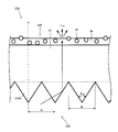
- FIG. 10 is an enlarged view of a part of the prism sheet 230 in FIG.
- n d represents the normal direction of the sheet surface of the main body 31.
- the unit prism 232 a has an isosceles triangular cross section that protrudes toward the light guide plate 221 of the main body 31. That is, the width of the sheet surface and parallel to the direction of the unit prisms 232a of the main body portion 31 becomes smaller with increasing distance from the body portion 231 along the normal direction n d of the body portion 231.
- the outer contour of the unit prisms 232a has a line symmetry with an axis parallel to the normal direction n d of the main body portion 231 as a symmetrical axis.
- this embodiment has a particularly isosceles triangle cross section.
- the luminance on the light exit surface of the prism sheet 230 has a symmetrical angular distribution of luminance about the front direction on the surface parallel to the arrangement direction of the unit prisms 232a.
- the dimension of the unit prism 232a is not particularly limited, but the apex angle ⁇ 10 (see FIG. 10) at the convex tip of the unit prism 232a is preferably 80 ° or less.
- the apex angle ⁇ 10 at the convex tip of the unit prism 232a is preferably 80 ° or less.
- More preferred apex angle theta 10 is 60 ° or more than 80 °.
- the base width W is preferably the same as the pitch P.
- the pitch P between adjacent unit prisms 232a is set to 10 ⁇ m or more. Other rules regarding the pitch P will be described later.
- the unit prism having a triangular cross-sectional shape as described above has been described.
- the present invention is not limited to this, and a trapezoid in which the apex of the triangle is a short upper base may be used.
- the slope may be a polygonal line or a curve. Therefore, the cross-sectional shape may be a polygon such as a quadrangle or a pentagon.
- the light diffusing layer 235 is a layer in which a large number of light diffusing particles 37 having a refractive index different from that of the light transmitting resin layer 36 are contained in the light transmitting resin layer 36. A part of the light diffusion particle 37 protrudes from the surface. Thereby, the surface of the light diffusion layer 235 is formed in an uneven surface.
- the material constituting the light diffusion layer 235 and the formation method thereof are the same as those of the light diffusion layer 35 described above.
- the surface roughness of the light-diffusion layer 235 is 0.038 micrometer or more by Ra (micrometer) (JISB0601 (2001) arithmetic mean roughness), and satisfy
- P is a pitch P ( ⁇ m) between adjacent unit prisms 232a in the unit prism portion 232 described above. That is, in this embodiment, Ra is 0.038 ⁇ m or more and is in a range satisfying the expression (3).
- the pitch P of the unit prisms 32a satisfies the above formula (3) in the range of 10 ⁇ m or more. If Ra of the light diffusing layer 235 is smaller than 0.038 ⁇ m, it does not function as a light diffusing layer and the concealability cannot be exhibited. On the other hand, if the pitch P of the unit prisms 232a is smaller than 10 ⁇ m, a product that can be mass-produced cannot be obtained due to a tool for producing a mold and a limit of processing accuracy at the time of molding.
- the haze (total haze) of the prism sheet 230 is dominated by the light diffusion layer 233.
- filling said Formula (3) even if the haze of the prism sheet 230 is 50% or less, there can exist the said effect.
- FIG. 9 shows, as an example, an optical path example of light L 91 and L 92 incident on the light guide plate 221 from the first lamp side light source 26.
- Lights L 91 and L 92 incident on the light guide plate 221 are totally reflected on the surface of the unit optical element portion 24 of the light guide plate 221 and the surface of the back prism portion 223 on the opposite side due to a difference in refractive index with air.
- the light emitted from the back surface is reflected by the reflection sheet 40 and returned to the light guide plate 221. Such reflection is repeated, and the light travels toward the second lamp-side light source 226 in the direction in which the ridge line of the unit optical element 24a extends (light guide direction).
- FIG. 9 shows an example of optical paths of light L 93 and L 94 that are incident on the light guide plate 221 from the second lamp side light source 226.
- Lights L 93 and L 94 incident on the light guide plate 221 are totally reflected on the surface of the unit optical element portion 24 of the light guide plate 221 and the surface of the back prism portion 223 on the opposite side due to a difference in refractive index with air.
- the light emitted from the back surface is reflected by the reflection sheet 40 and returned to the light guide plate 221. Such reflection is repeated, and the light travels toward the first lamp-side light source 26 in the direction in which the ridge line of the unit optical element 24a extends (light guide direction).
- a back prism portion 223 is formed on the back surface side of the base portion 22 of the light guide plate 221.
- the light L 91 , L 92 , L 93 , and L 94 traveling in the light guide plate 221 are sequentially changed in direction by the back surface prism portion 223, with an incident angle less than the total reflection critical angle.
- the light may enter the unit optical element portion 24.
- the light can be emitted from the surface of the unit optical element portion 24 of the light guide plate 221.
- Lights L 91 , L 92 , L 93 , and L 94 emitted from the unit optical element unit 24 travel to the prism sheet 230 disposed on the light output side of the light guide plate 21.
- the light traveling in the light guide plate 221 is gradually emitted from the light exit surface, and the light amount distribution along the light guide direction of the light emitted from the unit optical element portion 24 of the light guide plate 221 is made uniform. Can do.
- the unit optical element part 24 of the light guide plate 221 shown in the figure acts in the same manner as described above, the unit optical element part 24 collects light with respect to the light component along the direction orthogonal to the light guide direction. Will come to influence.
- the emission angle of light emitted from the light guide plate 221 is narrowed down to a narrow angle range centering on the front direction on a plane parallel to the arrangement direction of the unit optical elements 24a of the light guide plate 221.
- the light emitted from the light guide plate 221 then enters the prism sheet 230. Similar to the unit optical element 24a of the light guide plate 221, the unit prism 232a of the prism sheet 230 exerts a condensing action on the transmitted light by refraction and total reflection at the light incident surface of the unit prism 232a. However, the light whose direction of travel is changed by the prism sheet 230 is a component in a plane perpendicular to the arrangement direction of the unit prisms 232a of the prism sheet 230, and the component condensed by the light guide plate 221. Is different. That is, as indicated by L 101 in FIG.
- the light incident on the unit prism 232a is totally reflected at the interface based on the refractive index difference between the unit prism 232a and air. Then, the hypotenuse of the unit prisms 232a so that theta 10/2 inclined with respect to the seat surface normal n d, light reflection at the interface at an angle which is close to the normal n d than the incident light.
- the light guide plate 221 narrows the light traveling direction within a narrow angle range centering on the front direction on a plane parallel to the arrangement direction of the unit optical elements 24a of the light guide plate 221.
- the prism sheet 230 on the plane parallel to the arrangement direction of the unit prisms 232a, the light traveling direction is narrowed down to a narrow angle range centering on the front direction. Therefore, the front direction luminance can be further improved without impairing the front direction luminance raised by the light guide plate 221 by the optical action of the prism sheet 230.
- the light L 101 totally reflected by the unit prism 232 a passes through the main body 31, is diffused by the light diffusion layer 235, and is emitted from the prism sheet 230.
- the decrease in luminance is suppressed, as described above, the brightness of light having a high front luminance and whose direction is changed by the unit prism 232a can be efficiently emitted.
- the image definition is kept low, the concealability is sufficiently ensured. Also, glare is suppressed by the prism sheet 230.
- the light emitted from the prism sheet 230 enters the lower polarizing plate 14 of the liquid crystal panel 15.
- the lower polarizing plate 14 transmits one polarization component of incident light and absorbs the other polarization component.
- the light transmitted through the lower polarizing plate 14 is selectively transmitted through the upper polarizing plate 13 according to the state of electric field application to each pixel in the liquid crystal layer 12.
- the liquid crystal panel 15 selectively transmits light from the surface light source device 220 for each pixel, so that an observer of the liquid crystal display device can observe an image.
- liquid crystal display device provided with the video source unit of each form described above, various modes can be considered as its application. Examples thereof include a liquid crystal display, a television, a portable terminal, a car navigation, an electronic blackboard, an electronic advertising board, and the like.
- the surface light source device may be applied to lighting fixtures such as ceiling lighting and stand type lighting.
- Example 1 is an example related to the first aspect described above, that is, an example related to the formula (1).
- Example 1 prism sheets having different unit prism shapes, pitches, and surface roughness (Ra) of the light diffusion layer were prepared and compared. The conditions and results are shown below.
- the main body is common to each test body, and a 125 ⁇ m thick PET film (A4300 manufactured by Toyobo Co., Ltd.) was used.
- ⁇ Unit prism part> A unit prism portion in which unit prisms having a square cross-sectional shape shown in FIGS. 11 and 12 are arrayed on one surface of the main body portion using an ultraviolet curable resin (DIC Corporation, RC25-750). Specimens 1 to 15 were produced with the unit prism shape shown in FIG. In this embodiment, four different types of pitch P were prepared.
- the unit prisms of various pitches P have a shape in which the size in the pitch P direction is a ratio expressed in parentheses in FIG.
- the pitch P was made into four types, 18 micrometers, 34 micrometers, 54.5 micrometers, and 64 micrometers.
- Test bodies 16 and 17 having the unit prism shape shown in FIG. In this embodiment, the pitch P is 18 ⁇ m, the size in the direction of the pitch P is distributed at a ratio shown in parentheses in FIG. 12, and the angles are as shown in FIG.
- each light diffusion layer When forming the light diffusion layer, the following composition was prepared. By applying a light-dispersed particle dispersed in a resin (ink) that becomes a translucent resin layer to each light diffusing layer on the surface of the main body opposite to the unit prism portion and curing it. Formed.
- the configuration of each light diffusion layer is as follows.
- the resin (translucent resin, binder) of the translucent resin layer is the same for all compositions, and pentaerythritol triacrylate (refractive index of 1.51) was used.
- composition 1 Light diffusion particle / translucent resin (mass ratio): 7/100
- Light diffusing particles made of styrene resin, average particle diameter 2 ⁇ m (refractive index 1.59)
- the average particle diameter is an average particle diameter determined by a laser diffraction particle size distribution measurement method. The same applies hereinafter.
- Coating thickness 3 ⁇ m (2) Composition 2 Light diffusion particle / translucent resin (mass ratio): 7/100 Light diffusion particle A: made of styrene resin, average particle diameter of 2 ⁇ m (refractive index: 1.59) Light diffusing particles B: made of acrylic resin, average particle diameter 5 ⁇ m (refractive index 1.49) Light diffusing particle A / light diffusing particle B (mass ratio): 8.5 / 1.5 Coating thickness: 3 ⁇ m (3) Composition 3 Light diffusion particle / translucent resin (mass ratio): 10/100 Light diffusion particles: made of acrylic resin, average particle diameter 5 ⁇ m (refractive index 1.49) Coating thickness: 3 ⁇ m (4) Composition 4 Light diffusion particle / translucent resin (mass ratio): 8/100 Light diffusing particles: made of styrene resin, average particle size 3.5 ⁇ m (refractive index 1.59) Coating thickness: 1.5 ⁇ m (5) Composition 5 Light diffusion particle / translucent resin (mass ratio): 15/100 Light diffusing particles: made of urethane
- test body was formed as shown in Table 1. Note that the test body 11 is an example in which the light diffusion layer is not formed and only the main body portion and the unit prism portion are formed.
- Each specimen was evaluated for haze (total haze, internal haze, external haze), luminance ratio, surface roughness, glare index (scintillation index), visual observation of glare, and visual inspection of concealment. The results are shown together with Table 1.
- Table 1 shows whether or not the above formula (1) is satisfied. When “ ⁇ ” is satisfied, “ ⁇ ” is not satisfied.
- ⁇ Measurement of haze> The haze was measured by HM150 of Murakami Color Research Laboratory according to JIS K 7105, and this was defined as the total haze (haze). After the measurement of this haze, only a resin other than the light diffusing particles used in the light transmissive resin layer was prepared as an ink for the light diffusing layer and further applied, and all the light diffusing particles were buried in the light transmissive resin About this, the said haze measurement was performed and this was made into the internal haze. The difference between haze and internal haze was defined as external haze.
- the luminance ratio was represented by the ratio of the luminance of each test specimen to the luminance of the test specimen 11.
- the brightness was measured with a BM-7 manufactured by TOPCON at a solid angle of 1 ° from a height of 50 cm directly above the specimen. Since the test body 11 is not provided with a light diffusion layer, it is considered to be an example having the highest luminance.
- ⁇ Surface roughness> For the surface roughness, arithmetic average roughness Ra according to JIS B 0601 (2001) was measured. The measurement was carried out by Kosaka Laboratory Surfcorder SE1700 ⁇ .
- the test body is arranged on the light output side of the light source (white LED) and the light guide plate (the light guide plate 21 described above), and the liquid crystal panel (TN liquid crystal, 13.3 inch FHD) is installed on the light output side.
- the light source was turned on and the light exit surface of the liquid crystal panel was measured, and the in-plane color temperature deviation and the in-plane color temperature average value were obtained. More specifically, the 2.31 mm ⁇ 2.31 mm of the light emitting surface of the liquid crystal panel is divided into 50 ⁇ 50 (2500 pixels) using a chromaticity measuring device (Cybernet System Co., Ltd., ProMetric), and The color temperature was measured.
- Glare index deviation of color temperature / average value of color temperature (10)
- the inventors obtained knowledge that glare does not occur when the glare index is less than 0.110.
- FIG. 13 shows a graph of the test bodies 1 to 10 and the test bodies 12 to 17 in which the horizontal axis represents the unit prism pitch P ( ⁇ m) and the vertical axis represents the surface roughness Ra.
- FIG. 13 also shows the following equation (11) in which the right side and the left side of equation (1) are equal lines.
- Ra ⁇ 0.0296 ⁇ P + 1.944 (11)
- Equation (11) was obtained as follows. That is, for each pitch P, the glare index is smaller than 0.110 and closest to 0.110 (in this example, specimens 8, 9, and 10), and the glare index is larger than 0.110 and closest to 0.110. Based on the example (in this example, specimens 12, 13, and 14), the surface roughness Ra when the glare index becomes 0.110 is calculated for each pitch P by the ratio calculation (procedure 1), and the minimum is obtained from the result. Equation (11) was obtained by linear approximation by the square method (procedure 2). More details are as follows. Each of procedures 1 and 2 will be described.
- the surface roughness Ra when the glare index is 0.110 is calculated from the equation (12) for each.
- the pitch P is 18.0 ⁇ m.
- the test body 8 and the test body 12 correspond, the surface roughness Ra is 1.403 ⁇ m (Ra 1 ), 1.573 ⁇ m (Ra 2 ), and the glare index is 0.1096 (G 1 ), 0.1218 (G 2 ).
- Expression (12) when the surface roughness Ra to be 0.110 when the pitch P is 18 ⁇ m is used in Expression (12), the following Expression (13) is obtained.
- 1.403 + ⁇ (1.573-1.403) / (0.1218-0.1009) ⁇ ⁇ (0.110-0.1096) 1.4085738 (13)
- n 3
- x may be a pitch P
- y may be a surface roughness Ra.
- the expressions (14) and (15) are specifically expressed as the expressions (16) and (17), and specific values can be obtained.
- Example 2 is an example related to the above-described second form, that is, an example related to the expression (2).
- Example 2 prism sheets having different unit prism shapes, pitches, and surface roughness (Ra) of the light diffusion layer were prepared and compared. The conditions and results are shown below.
- the main body is common to each test body, and a 125 ⁇ m thick PET film (A4300 manufactured by Toyobo Co., Ltd.) was used.
- ⁇ Unit prism part> A unit prism portion in which unit prisms having a cross-sectional shape according to FIG. 8 are arrayed on one surface of the main body portion using an ultraviolet curable resin (DIC Corporation, RC25-750, post-curing refractive index 1.51). did.
- the pitch P was made into four types, 18 micrometers, 34 micrometers, 54.5 micrometers, and 64 micrometers.
- each light diffusion layer When forming the light diffusion layer, the following composition was prepared. By applying a light-dispersed particle dispersed in a resin (ink) that becomes a translucent resin layer to each light diffusing layer on the surface of the main body opposite to the unit prism portion and curing it. Formed.
- the configuration of each light diffusion layer is as follows.
- the resin (translucent resin, binder) of the translucent resin layer is the same for all compositions, and pentaerythritol triacrylate (refractive index of 1.51) was used.
- Composition 11 Light diffusion particle / translucent resin (mass ratio): 20/100
- Light diffusing particles Polyurethane made of urethane resin with an average particle diameter of 6 ⁇ m (refractive index 1.51, Negami Industrial Co., Ltd. Art Pearl (registered trademark) C-800 transparent) Coating thickness: 3 ⁇ m
- Composition 12 Light diffusion particle / translucent resin (mass ratio): 10/100
- Light diffusing particles made of acrylic resin, average particle size 5 ⁇ m (refractive index 1.49, Sekisui Plastics Co., Ltd.
- Light diffusing particles B made of acrylic resin, average particle diameter 5 ⁇ m (refractive index 1.49, Sekisui Plastics Co., Ltd. Techpolymer (registered trademark) SSX-105) Light diffusing particle A / light diffusing particle B (mass ratio): 8.5 / 1.5 Coating thickness: 3 ⁇ m (5) Composition 15 Light diffusion particle / translucent resin (mass ratio): 9/100 Light diffusing particles: made of acrylic resin, average particle size 10 ⁇ m (refractive index 1.49, Sekisui Plastics Co., Ltd.
- test body 29 is an example in which the light diffusing layer is not formed, and only the main body portion and the unit prism portion by the unit prism described above based on FIG.
- FIG. 14 is a graph of the test bodies 21 to 28 in which the horizontal axis represents the unit prism pitch P ( ⁇ m) and the vertical axis represents the surface roughness Ra ( ⁇ m).
- FIG. 14 also shows the following formula (18), which is a line in which the right side and the left side of formula (2) are equal.
- Ra -0.0263 ⁇ P + 2.0537 (18)
- equation (18) was obtained by using a method similar to the method of deriving equation (11) in Example 1 based on the results of test bodies 21 to 28.
- Specimens 21 to 24 were excellent in both glare visual observation and concealment, and the glare index at this time was 0.108 or more and 0.110 or less. On the other hand, all of the test bodies 25 to 28 did not satisfy the requirements for glare, although the same unit prism (FIG. 8) was used.
- Example 3 is an example related to the above-described third form, that is, an example related to the expression (3).
- prism sheets having different unit prism shapes, pitches, and surface roughness (Ra) of the light diffusion layer were prepared and compared. The conditions and results are shown below.
- the main body is common to each test body, and a 125 ⁇ m thick PET film (A4300 manufactured by Toyobo Co., Ltd.) was used.
- the test body 40 was produced from the test body 31 in the unit prism shape shown in FIG. In this embodiment, four different types of pitch P were prepared.
- the unit prisms of various pitches P have a shape in which the angle in the pitch P direction is a ratio expressed in parentheses in FIG.
- the pitch P was made into four types, 34 micrometers, 50 micrometers, 64 micrometers, and 75 micrometers.
- each light diffusion layer When forming the light diffusion layer, the following composition was prepared. By applying a light-dispersed particle dispersed in a resin (ink) that becomes a translucent resin layer to each light diffusing layer on the surface of the main body opposite to the unit prism portion and curing it. Formed.
- the configuration of each light diffusion layer is as follows.
- the resin (translucent resin, binder) of the translucent resin layer is the same for all compositions, and pentaerythritol triacrylate (refractive index 1.51) was used.
- composition 21 Light diffusion particle / translucent resin (mass ratio): 10/100
- Light diffusion particles made of acrylic resin, average particle diameter 5 ⁇ m (refractive index 1.49)
- the average particle diameter is an average particle diameter determined by a laser diffraction particle size distribution measurement method. The same applies hereinafter.
- Coating thickness 3 ⁇ m (2) Composition 22 Light diffusion particle / translucent resin (mass ratio): 15/100 Light diffusion particles: made of acrylic resin, average particle diameter 5 ⁇ m (refractive index 1.49) Coating thickness: 3 ⁇ m (3) Composition 23 Light diffusion particle / translucent resin (mass ratio): 8/100 Light diffusion particles: made of acrylic resin, average particle diameter 5 ⁇ m (refractive index 1.49) Coating thickness: 3 ⁇ m (4) Composition 24 Light diffusion particle / translucent resin (mass ratio): 9/100 Light diffusing particles: made of styrene resin, average particle diameter 2 ⁇ m (refractive index 1.59) Coating thickness: 1.5 ⁇ m (5) Composition 25 Light diffusion particle / translucent resin (mass ratio): 7/100 Light diffusing particles: made of styrene resin, average particle diameter 2 ⁇ m (refractive index 1.59) Coating thickness: 1.5 ⁇ m (6) Composition 26 Light diffusion particle / translucent resin (mass ratio): 8/100 Light diffusing particles: made of sty
- the test body 37 is an example in which the light diffusion layer is not formed and only the main body portion and the unit prism portion are provided.
- Each specimen was evaluated in the same manner as in Example 1. However, in this example, illumination is performed by a two-lamp type (see FIG. 9).
- FIG. 17 shows a graph of the test bodies 31 to 36 and the test bodies 38 to 42, in which the horizontal axis represents the unit prism pitch P ( ⁇ m) and the vertical axis represents the surface roughness Ra ( ⁇ m). .
- FIG. 17 also shows the following equation (19) in which the right side and the left side of equation (3) are equal lines.
- Ra -0.0208 ⁇ P + 2.0223 (19)
- the number of the test specimen is indicated with “No”.
- Formula (19) was obtained by the same method as the method of deriving Formula (11) in Example 1 based on the results of the test bodies 32, 34, 36, 38, 39, and 40.
- the pitch P when the glare index is 0.110 is also calculated by ratio calculation, and the calculated pitch is calculated by an approximate expression using the least square method.
- the glare index of a specimen with a glare index less than 0.110 is G 1
- the pitch P is P 1
- the glare index of a specimen with a glare index greater than 0.110 is G 2 , determined by the following equation (20) when the pitch P was P 2.
Landscapes
- Physics & Mathematics (AREA)
- General Physics & Mathematics (AREA)
- Optics & Photonics (AREA)
- Chemical & Material Sciences (AREA)
- Nonlinear Science (AREA)
- Dispersion Chemistry (AREA)
- Mathematical Physics (AREA)
- Crystallography & Structural Chemistry (AREA)
- Planar Illumination Modules (AREA)
- Optical Elements Other Than Lenses (AREA)
Abstract
Description
Ra≦-0.0296・P+1.9441
が成り立つ、プリズムシートである。
Ra≦-0.0263・P+2.0537
が成り立つ、プリズムシートである。
Ra≦-0.0208・P+2.0223
が成り立つ、プリズムシートである。
液晶表示装置1は、映像源ユニット10を有しており、映像源ユニット10に含まれる面光源装置20から出射された白色の光源光が液晶パネル15を透過して映像情報を得てから観察者側に提供される。
面光源装置20は、液晶パネル15を挟んで観察者側とは反対側に配置され、液晶パネル15に面状の光を出射する照明装置である。図2~図4よりわかるように、本形態では面光源装置20は、エッジライト型の面光源装置として構成され、導光板21、光源26、プリズムシート30、及び反射シート40を有している。
本形態の単位裏面プリズム23aは断面が三角形であるがこれに限定されることはなく、四角形や五角形等の多角形、半球状、球の一部、レンズ形状等いずれの形状であってもよい。なお、単位裏面プリズム23aの断面形状は導光板における公知の形態を適用することができる。
本形態で単位光学要素24aは、図2、図4に表されるように断面五角形を有し該断面を維持してその稜線が一方に延びる柱状の要素である。単位光学要素24aの稜線が延在する方向は、単位光学要素24aが配列される方向及び単位裏面プリズム23aの稜線が延びる方向に対して直交する方向である。すなわち単位光学要素24aはその稜線が単位裏面プリズム23aの稜線と平面視で直交するように構成されている。
また、単位光学要素部24は必ずしも設けられている必要はなく、基部22の平滑面が出光面とされてもよい。
一方、基部22の厚さは、0.20mm以上6mm以下とすることができる。
本形態では光源26は、単位光学要素24aの稜線が延びる方向の両端となる一組の側面の一方に配置される例であるが、当該一組の両方に光源が配置されることを妨げるものではない。
Ra≦-0.0296・P+1.9441 (1)
光拡散層35のRaが0.038μmより小さいと光拡散層として機能せず、隠蔽性を発揮することができない。また、単位プリズム32aのピッチPが10μmより小さいと、金型を作製する工具、及び成型時における加工精度の限界により、実質上、量産できる製品を得ることができない。
次に本体部31となる基材の他方の面に単位プリズム部32を賦型すればプリズムシート30となる。
本体部31及び単位プリズム部32をなす材料としては、種々の材料を使用することができる。ただし、表示装置に組み込まれる光学シート用の材料として広く使用され、優れた機械的特性、光学特性、安定性及び加工性等を有するとともに安価に入手可能な材料、例えば、アクリル、スチレン、ポリカーボネート、ポリエチレンテレフタレート、アクリロニトリル等の一以上を主成分とする透明樹脂や、エポキシアクリレートやウレタンアクリレート系の反応性樹脂(電離放射線硬化型樹脂等)が好適に使用され得る。
また、導光板21の裏面プリズム部23側には反射シート40が配置される。一方、導光板21の単位光学要素部24側にはプリズムシート30が配置される。プリズムシート30はその単位プリズム32aの稜線が導光板21の単位光学要素24aの稜線に対して正面視で直交する向きとされる。このとき単位プリズム32aの入光面33が光源26側、その反対側が反射面34となるように配置される。
そしてプリズムシート30を挟んで導光板21とは反対側に液晶パネル15、さらに液晶パネル15の観察者側に機能性シート41が配置される。
これにより導光板21内を進む光は、少しずつ、出光面から出射するようになり、導光板21の単位光学要素部24から出射する光の導光方向に沿った光量分布を均一化させることができる。
またプリズムシート30によりギラツキも抑制されている。
0.525≦VIIIa≦0.545
0.100≦VIIIb≦0.120
0.130≦VIIIc≦0.150
0.205≦VIIId≦0.225
Ra≦-0.0263・P+2.0537 (2)
光拡散層135のRaが0.038μmより小さいと光拡散層として機能せず、隠蔽性を発揮することができない。また、単位プリズム132aのピッチPが10μmより小さいと、金型を作製する工具、及び成型時における加工精度の限界により、実質上、量産できる製品を得ることができない。
また、導光板21の裏面プリズム部23側には反射シート40が配置される。一方、導光板21の単位光学要素部24側にはプリズムシート130が配置される。プリズムシート130はその単位プリズム132aの稜線が導光板21の単位光学要素24aの稜線に対して正面視で直交する向きとされる。このとき単位プリズム132aの入光面133が光源26側、その反対側が反射面134となるように配置される。
そしてプリズムシート130を挟んで導光板21とは反対側に液晶パネル15、さらに液晶パネル15の観察者側に機能性シート41が配置される。
またその際にはプリズムシート130の反射面134の作用により、適度に拡散された光が反射される。
またプリズムシート130によりギラツキも抑制されている。
第一灯側光源26は、導光板21の基部22の2組の側面のうち、単位光学要素24aの稜線が延びる方向である長手方向両端となる一組の側面の一方側に配置されている光源である。
第二灯側光源226は、導光板21の基部22の2組の側面のうち、単位光学要素24aの稜線が延びる方向である長手方向両端となる一組の側面の他方側に配置されている光源である。そして第二灯光源226は第一灯光源26側に向けて光を出射する。
第一灯側光源26も第二灯側光源226も光源の種類は特に限定されるものではないが、線状の冷陰極管等の蛍光灯、点状のLED(発光ダイオード)形態、又は白熱電球等の種々の態様で構成され得る。
Ra≦-0.0208・P+2.0223 (3)
光拡散層235のRaが0.038μmより小さいと光拡散層として機能せず、隠蔽性を発揮することができない。また、単位プリズム232aのピッチPが10μmより小さいと、金型を作製する工具、及び成型時における加工精度の限界により、実質上、量産できる製品を得ることができない。
導光板221に入射した光L91、L92は、導光板221の単位光学要素部24の面及びその反対側の裏面プリズム部223の面において、空気との屈折率差により全反射する。また、図示は省略するが裏面から出光した光は反射シート40により反射して導光板221内に戻される。このような反射を繰り返し、光は単位光学要素24aの稜線が延びる方向(導光方向)の第二灯側光源226の方に進んでいく。
導光板221に入射した光L93、L94は、導光板221の単位光学要素部24の面及びその反対側の裏面プリズム部223の面において、空気との屈折率差により全反射する。また、図示は省略するが裏面から出光した光は反射シート40により反射して導光板221内に戻される。このような反射を繰り返し、光は単位光学要素24aの稜線が延びる方向(導光方向)の第一灯側光源26の方に進んでいく。
これにより導光板221内を進む光は、少しずつ、出光面から出射するようになり、導光板221の単位光学要素部24から出射する光の導光方向に沿った光量分布を均一化させることができる。
またプリズムシート230によりギラツキも抑制されている。
実施例1は上記した第一の形態に関する例であり、すなわち、式(1)に関連する例である。実施例1では、単位プリズムの形状、ピッチ及び光拡散層の表面粗さ(Ra)が異なるプリズムシートを準備して比較をした。以下に条件及び結果を示す。
本体部は各試験体で共通としており、厚さ125μmのPETフィルム(東洋紡株式会社製A4300)を用いた。
本体部の一方に面に、紫外線硬化樹脂(DIC株式会社、RC25-750)を用いて図11、図12に示した4角形の断面形状を有する単位プリズムが配列した単位プリズム部を成型した。
図11に示した単位プリズム形状で試験体1から試験体15を作製した。この形態では、ピッチPは異なる4種類を準備した。各種ピッチPの単位プリズムは、ピッチP方向の大きさを図11に括弧書きで表した比率とし、角度が一定である形状とした。ピッチPは、18μm、34μm、54.5μm、64μmの4種類とした。
図12に示した単位プリズム形状で試験体16、17を作製した。この形態では、ピッチPは18μmとし、ピッチP方向の大きさを図12に括弧書きで表した比率で配分し、角度は図12に示した通りである。
光拡散層を形成するに際して次の組成のものを準備した。各光拡散層とも透光性樹脂層となる樹脂(インキ)中に光拡散粒子を分散したものを本体部のうち単位プリズム部とは反対側となる面にコーターにより塗布して硬化することにより形成した。各光拡散層の構成は次の通りである。ここで全ての組成について透光性樹脂層の樹脂(透光性樹脂、バインダー)はいずれも同じであり、ペンタエリスリトールトリアクリレート(屈折率1.51)を用いた。
(1)組成1
光拡散粒子/透光性樹脂(質量比):7/100
光拡散粒子:スチレン樹脂製、平均粒子径2μm(屈折率 1.59)
ここで平均粒子径は、レーザー回折式粒度分布測定法により求められた平均粒子径である。以下同様である。
塗工厚:3μm
(2)組成2
光拡散粒子/透光性樹脂(質量比):7/100
光拡散粒子A:スチレン樹脂製、平均粒子径2μm(屈折率 1.59)
光拡散粒子B:アクリル樹脂製、平均粒子径5μm(屈折率 1.49)
光拡散粒子A/光拡散粒子B(質量比):8.5/1.5
塗工厚:3μm
(3)組成3
光拡散粒子/透光性樹脂(質量比):10/100
光拡散粒子:アクリル樹脂製、平均粒子径5μm(屈折率1.49)
塗工厚:3μm
(4)組成4
光拡散粒子/透光性樹脂(質量比):8/100
光拡散粒子:スチレン樹脂製、平均粒子径3.5μm(屈折率1.59)
塗工厚:1.5μm
(5)組成5
光拡散粒子/透光性樹脂(質量比):15/100
光拡散粒子:ウレタン樹脂製、平均粒子径6μmの多分散(屈折率1.43)
塗工厚:3μm
(6)組成6
光拡散粒子/透光性樹脂(質量比):9/100
光拡散粒子:アクリル樹脂製、平均粒子径5μm(屈折率1.49)
塗工厚:3μm
(7)組成7
光拡散粒子/透光性樹脂(質量比):7/100
光拡散粒子A:スチレン樹脂製、平均粒子径2μm(屈折率1.59)
光拡散粒子B:アクリル樹脂製、平均粒子径5μm(屈折率1.49)
光拡散粒子A/光拡散粒子B(質量比):9.0/1.0
塗工厚:3μm
(8)組成8
光拡散粒子/透光性樹脂(質量比):4/100
光拡散粒子:アクリル樹脂製、平均粒子径5μm(屈折率1.49)
塗工厚:3μm
(9)組成9
光拡散粒子/透光性樹脂(質量比):7/100
光拡散粒子:スチレン樹脂製、平均粒子径2μm(屈折率1.59)
塗工厚:1.5μm
(10)組成10
光拡散粒子/透光性樹脂(質量比):20/100
光拡散粒子:ウレタン樹脂製、平均粒子径6μmの多分散(屈折率1.43)
塗工厚:3μm
また、表1には上記式(1)を満たすか否かを表した。「○」が満たす場合、「×」が満さない場合である。
ヘイズの測定はJIS K 7105に沿って村上色彩技術研究所のHM150により測定してこれを全ヘイズ(ヘイズ)とした。このヘイズの測定の後、光拡散層に対して透光性樹脂層に用いた光拡散粒子以外の樹脂のみをインキとして調製してさらに塗布し、光拡散粒子を全て透光性樹脂に埋め、これについて上記ヘイズ測定を行いこれを内部ヘイズとした。そしてヘイズと内部ヘイズとの差を外部ヘイズとした。
輝度比は、試験体11の輝度に対する各試験体の輝度の比率により表した。輝度は、TOPCON社製のBM-7により、試験体の直上50cmの高さから、立体角1°にて測定した。試験体11は光拡散層が具備されていないため最も輝度が高い例であると考えられる。
表面粗さはJIS B 0601(2001)による算術平均粗さRaを測定した。測定は小坂研究所 Surfcorder SE1700αにより行った。
光源(白色LED)及び導光板(上記した導光板21)の出光側に上記試験体を配置し、さらにその出光側に上記液晶パネル(TN液晶、13.3インチのFHD)を設置する。光源を点灯し液晶パネルの出光面の測定を行ない、面内の色温度の偏差、及び面内の色温度の平均値を得た。より具体的には、液晶パネルの出光面の2.31mm×2.31mmに対し、色度測定機(サイバネットシステム株式会社、ProMetric)を用いて50×50分割(2500画素)し、画素ごとに色温度を測定した。そして取得した色温度の偏差、及び色温度の平均値から下記式(10)によりギラツキ指標を算出した。
ギラツキ指標=色温度の偏差/色温度の平均値 (10)
ここで発明者らはギラツキ指標が0.110未満であることにより、ギラツキが発生しない知見を得た。
ギラツキ及び隠蔽性について従来と同様に目視で評価をおこなった。ギラツキは、発生しなかった場合に「◎」、発生があったが許容範囲である場合に「○」、許容できないほど発生した場合には「×」とした。一方、隠蔽性については、光源上にプリズムシートを置き、透過観察で正面から±45°の範囲内で上下左右を観察したとき、虹色に輝く帯(虹ムラ)が完全に見えない場合を「◎」、見えるが許容範囲の場合を「○」、許容できないほど見える場合を「×」とした。

Ra=-0.0296・P+1.9441 (11)
なお、図13中の各プロットの近傍には、試験体の番号を「No」を付して表記した。
手順1ではピッチPごとにギラツキ指標が0.110となるときの表面粗さRaを比率計算で算出する。すなわちあるピッチPについて、ギラツキ指標が0.110を下回る試験体のギラツキ指標をG1、表面粗さRaをRa1とし、ギラツキ指標が0.110を上回る試験体のギラツキ指標をG2、表面粗さRaをRa2としたとき下記式(12)により求めることができる。
Ra1+{(Ra2-Ra1)/(G2-G1)}×(0.110-G1) (12)
例としてピッチPが18.0μmの場合について考える。ピッチPが18.0μmは試験体8及び試験体12が該当し、それぞれの表面粗さRaは1.403μm(Ra1)、1.573μm(Ra2)で、ギラツキ指標は0.1096(G1)、0.1218(G2)である。このデータを用いてピッチPが18μmのときにおける0.110となるための表面粗さRaを式(12)用いると次の式(13)のようになる。
1.403+{(1.573-1.403)/(0.1218-0.1096)}×(0.110-0.1096)=1.4085738 (13)

次に手順1で求めた表2の3つの点を用いて最小二乗法により直線近似式を算出する。当該直線近似式は、aを係数、bをy切片とすればf(x)=ax+bとなり、a、bはそれぞれ次の式(14)、式(15)により得ることができる。
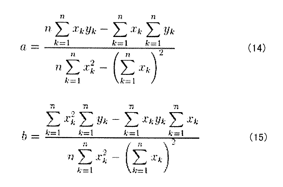
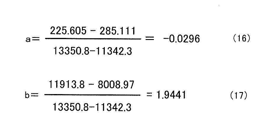
実施例2は上記した第二の形態に関する例であり、すなわち、式(2)に関連する例である。実施例2では、単位プリズムの形状、ピッチ及び光拡散層の表面粗さ(Ra)が異なるプリズムシートを準備して比較をした。以下に条件及び結果を示す。
本体部は各試験体で共通としており、厚さ125μmのPETフィルム(東洋紡株式会社製A4300)を用いた。
本体部の一方に面に、紫外線硬化樹脂(DIC株式会社、RC25-750、硬化後屈折率1.51)を用いて図8に倣った断面形状を有する単位プリズムが配列した単位プリズム部を成型した。ピッチPは異なる4種類を準備した。単位プリズムの具体的な形態は図8に示した記号を用いると次のとおりである。
θ7=75°
θ81=174°
θ82=173°
VIIIa=0.5338
VIIIb=0.1111
VIIIc=0.1388
VIIId=0.2162
ピッチPは18μm、34μm、54.5μm、64μmの4種類とした。
光拡散層を形成するに際して次の組成のものを準備した。各光拡散層とも透光性樹脂層となる樹脂(インキ)中に光拡散粒子を分散したものを本体部のうち単位プリズム部とは反対側となる面にコーターにより塗布して硬化することにより形成した。各光拡散層の構成は次の通りである。ここで全ての組成について透光性樹脂層の樹脂(透光性樹脂、バインダー)はいずれも同じであり、ペンタエリスリトールトリアクリレート(屈折率1.51)を用いた。
(1)組成11
光拡散粒子/透光性樹脂(質量比):20/100
光拡散粒子:ウレタン樹脂製、平均粒子径6μmの多分散(屈折率1.51、根上工業株式会社 アートパール(登録商標) C-800透明)
塗工厚:3μm
(2)組成12
光拡散粒子/透光性樹脂(質量比):10/100
光拡散粒子:アクリル樹脂製、平均粒子径5μm(屈折率1.49、積水化成品工業株式会社 テクポリマー(登録商標) SSX-105)
塗工厚:3μm
(3)組成13
光拡散粒子/透光性樹脂(質量比):4/100
光拡散粒子:アクリル樹脂製、平均粒子径5μm(屈折率1.49、積水化成品工業株式会社 テクポリマー(登録商標) SSX-105)
塗工厚:3μm
(4)組成14
光拡散粒子/透光性樹脂(質量比):7/100
光拡散粒子A:スチレン樹脂製、平均粒子径2μm(屈折率1.59、積水化成品工業株式会社 テクポリマー(登録商標) SSX-302ABE)
光拡散粒子B:アクリル樹脂製、平均粒子径5μm(屈折率1.49、積水化成品工業株式会社 テクポリマー(登録商標) SSX-105)
光拡散粒子A/光拡散粒子B(質量比):8.5/1.5
塗工厚:3μm
(5)組成15
光拡散粒子/透光性樹脂(質量比):9/100
光拡散粒子:アクリル樹脂製、平均粒子径10μm(屈折率1.49、積水化成品工業株式会社 テクポリマー(登録商標) SSX-110)
塗工厚:3μm
(6)組成16
光拡散粒子/透光性樹脂(質量比):9/100
光拡散粒子:アクリル樹脂製、平均粒子径8μm(屈折率1.49、積水化成品工業株式会社 テクポリマー(登録商標) SSX-108)
塗工厚:3μm
(7)組成17
光拡散粒子/透光性樹脂(質量比):9/100
光拡散粒子:アクリル樹脂製、平均粒子径5μm(屈折率1.49、積水化成品工業株式会社 テクポリマー(登録商標) SSX-105)
塗工厚:3μm
試験体21~試験体28は図8に基づいた上記した単位プリズムを適用した。
試験体29は光拡散層を形成せず、本体部及び図8に基づいた上記した単位プリズムによる単位プリズム部のみとした例である。
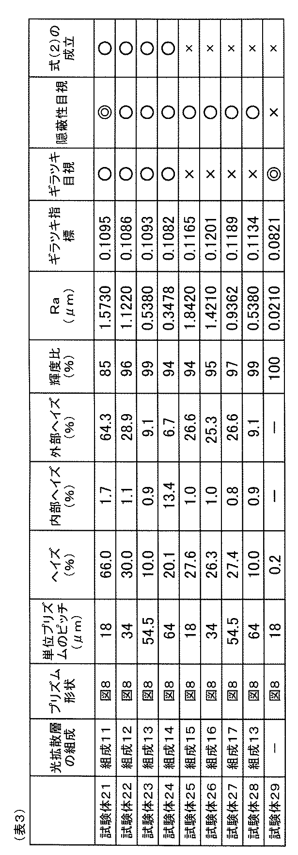
Ra=-0.0263・P+2.0537 (18)
なお、図14中の各プロットの近傍には、試験体の番号を「No」を付して表記した。また、式(18)は試験体21~試験体28の結果に基づき、実施例1で式(11)を導出する方法と同様の方法を用いることで得た。
実施例3は上記した第三の形態に関する例であり、すなわち、式(3)に関連する例である。実施例3では、単位プリズムの形状、ピッチ及び光拡散層の表面粗さ(Ra)が異なるプリズムシートを準備して比較をした。以下に条件及び結果を示す。
本体部は各試験体で共通としており、厚さ125μmのPETフィルム(東洋紡株式会社製A4300)を用いた。
本体部の一方に面に、紫外線硬化樹脂(DIC株式会社、RC25-750)を用いて図15、図16に示した線対称である5角形の断面形状を有する単位プリズムが配列した単位プリズム部を成型した。
図15に示した単位プリズム形状で試験体31から試験体40を作製した。この形態では、ピッチPは異なる4種類を準備した。各種ピッチPの単位プリズムは、ピッチP方向の大きさを図15に括弧書きで表した比率とし、角度が一定である形状とした。ピッチPは、34μm、50μm、64μm、75μmの4種類とした。
図16に示した単位プリズム形状で試験体41、42を作製した。この形態では、ピッチPは34μmとし、ピッチP方向の大きさを図16に括弧書きで表した比率で配分し、角度は図16に示した通りである。
光拡散層を形成するに際して次の組成のものを準備した。各光拡散層とも透光性樹脂層となる樹脂(インキ)中に光拡散粒子を分散したものを本体部のうち単位プリズム部とは反対側となる面にコーターにより塗布して硬化することにより形成した。各光拡散層の構成は次の通りである。ここで全ての組成について透光性樹脂層の樹脂(透光性樹脂、バインダー)はいずれも同じであり、ペンタエリスリトールトリアクリレート(屈折率1.51)を用いた。
(1)組成21
光拡散粒子/透光性樹脂(質量比):10/100
光拡散粒子:アクリル樹脂製、平均粒子径5μm(屈折率1.49)
ここで平均粒子径は、レーザー回折式粒度分布測定法により求められた平均粒子径である。以下同様である。
塗工厚:3μm
(2)組成22
光拡散粒子/透光性樹脂(質量比):15/100
光拡散粒子:アクリル樹脂製、平均粒子径5μm(屈折率1.49)
塗工厚:3μm
(3)組成23
光拡散粒子/透光性樹脂(質量比):8/100
光拡散粒子:アクリル樹脂製、平均粒子径5μm(屈折率1.49)
塗工厚:3μm
(4)組成24
光拡散粒子/透光性樹脂(質量比):9/100
光拡散粒子:スチレン樹脂製、平均粒子径2μm(屈折率1.59)
塗工厚:1.5μm
(5)組成25
光拡散粒子/透光性樹脂(質量比):7/100
光拡散粒子:スチレン樹脂製、平均粒子径2μm(屈折率1.59)
塗工厚:1.5μm
(6)組成26
光拡散粒子/透光性樹脂(質量比):8/100
光拡散粒子:スチレン樹脂製、平均粒子径3.5μm(屈折率1.59)
塗工厚:1.5μm
(7)組成27
光拡散粒子/透光性樹脂(質量比):20/100
光拡散粒子:ウレタン樹脂製、平均粒子径6μmの多分散(屈折率1.43)
塗工厚:3μm
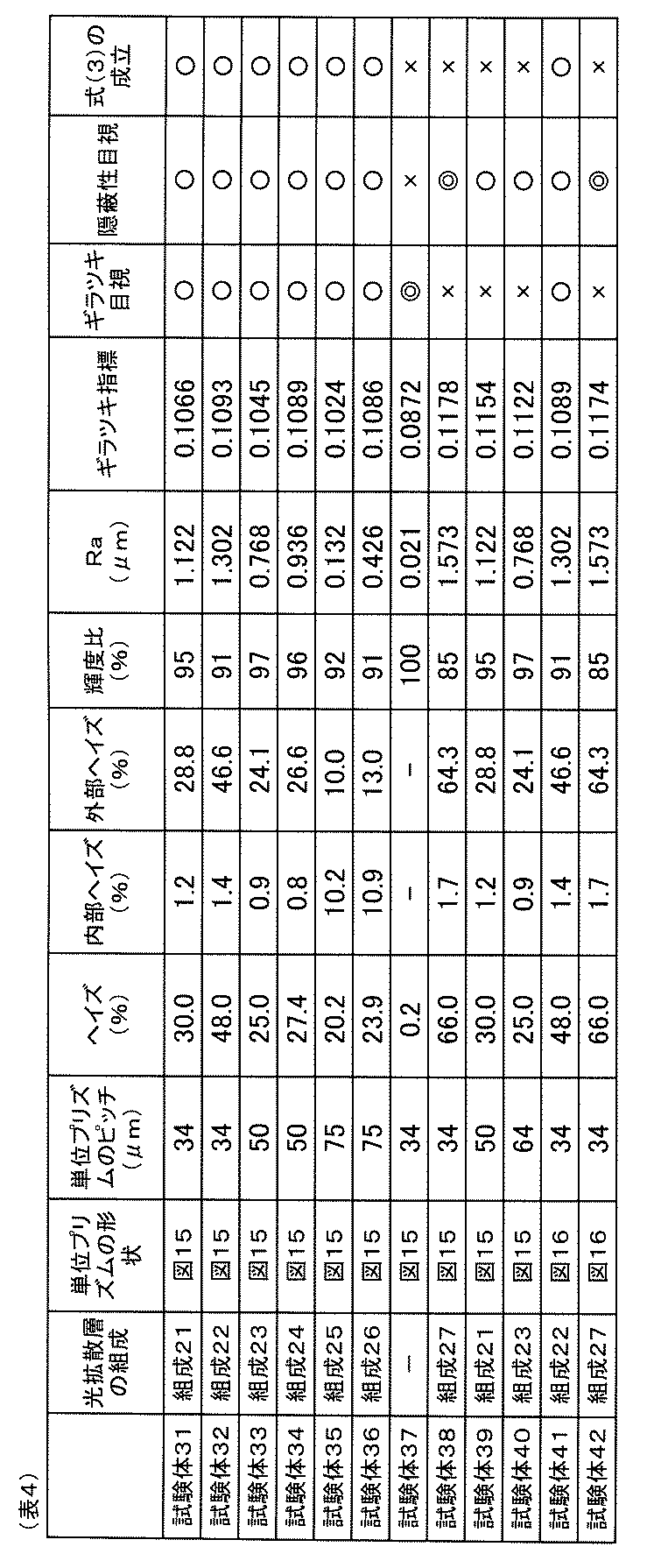
Ra=-0.0208・P+2.0223 (19)
なお、図17中の各プロットの近傍には、試験体の番号を「No」を付して表記した。また、式(19)は、試験体32、34、36、38、39、40の結果に基づき、実施例1で式(11)を導出する方法と同様の方法で得た。ただし、試験体36と試験体40に関してはピッチPが異なるため、さらにギラツキ指標が0.110となるときのピッチPについても比率計算で算出し、算出したピッチを最小二乗法による近似式計算のときに用いる。すなわち、ある表面粗さRaについて、ギラツキ指標が0.110を下回る試験体のギラツキ指標をG1、ピッチPをP1とし、ギラツキ指標が0.110を上回る試験体のギラツキ指標をG2、ピッチPをP2としたとき下記式(20)により求める。
P1+{(P2-P1)/(G2-G1)}×(0.110-G1) (20)
12 液晶層
13、14 偏光板
15 液晶パネル
20 面光源装置
21 導光板
22 基部
23 裏面プリズム部
23a 単位裏面プリズム
24 単位光学要素部
24a 単位光学要素
26 光源
30、130、230 プリズムシート
31 本体部
32、132、232 単位プリズム部
32a、132a、232a 単位プリズム
35、135、235 光拡散層
36 透光性樹脂層
37 光拡散粒子
Claims (6)
- 入射した光の向きを変えて出射するプリズムシートであって、
光透過性を有するシート状の本体部と、
前記本体部の一方の面側に配置され、複数の凸状の単位プリズムがシート面に沿った方向に配列された単位プリズム部と、
前記本体部の他方の面側に配置された光拡散層と、を備え、
前記単位プリズムは、前記凸状の先端における頂角が80°以下であり、
前記複数の単位プリズムのピッチをP(μm)、前記光拡散層の表面粗さをRa(μm)としたとき、
Ra≦-0.0296・P+1.9441
が成り立つ、プリズムシート。 - 入射した光の向きを変えて出射するプリズムシートであって、
光透過性を有するシート状の本体部と、
前記本体部の一方の面側に配置され、複数の凸状の単位プリズムがシート面に沿った方向に配列された単位プリズム部と、
前記本体部の他方の面側に配置された光拡散層と、を備え、
前記単位プリズムは、前記凸状の先端となる頂点を挟んで一方側が入光面、他方側が反射面とされ、前記反射面は傾斜角度が異なる3つの面からなり、
前記複数の単位プリズムのピッチをP(μm)、前記光拡散層の表面粗さをRa(μm)としたとき、Pは10μm以上、Raは0.035μm以上であり、かつ、
Ra≦-0.0263・P+2.0537
が成り立つ、プリズムシート。 - 入射した光の向きを変えて出射するプリズムシートであって、
光透過性を有するシート状の本体部と、
前記本体部の一方の面側に配置され、複数の凸状の単位プリズムがシート面に沿った方向に配列された単位プリズム部と、
前記本体部の他方の面側に配置された光拡散層と、を備え、
前記単位プリズムは、対称形からなるとともに前記凸状の先端における頂角が80°以下であり、
前記複数の単位プリズムのピッチをP(μm)、前記光拡散層の表面粗さをRa(μm)としたとき、
Ra≦-0.0208・P+2.0223
が成り立つ、プリズムシート。 - 光源と、
前記光源から出射した光を導光する導光板と、
前記導光板の出光面側に配置される請求項1乃至3のいずれかに記載のプリズムシートと、を備える面光源装置。 - 請求項4に記載の面光源装置と、
前記面光源装置の出光側に配置された液晶パネルと、を備える映像源ユニット。 - 請求項5に記載の映像源ユニットと、
前記映像源ユニットを内包する筐体と、を備える液晶表示装置。
Priority Applications (3)
| Application Number | Priority Date | Filing Date | Title |
|---|---|---|---|
| KR1020167009763A KR20160062043A (ko) | 2013-09-26 | 2014-09-26 | 프리즘 시트, 면 광원 장치, 영상원 유닛 및 액정 표시 장치 |
| CN201480063049.XA CN105745558A (zh) | 2013-09-26 | 2014-09-26 | 棱镜片、面光源装置、映像源单元及液晶显示设备 |
| US15/025,096 US20160259115A1 (en) | 2013-09-26 | 2014-09-26 | Prism sheet, surface light source device, image source unit, and liquid crystal display device |
Applications Claiming Priority (4)
| Application Number | Priority Date | Filing Date | Title |
|---|---|---|---|
| JP2013-200516 | 2013-09-26 | ||
| JP2013-200515 | 2013-09-26 | ||
| JP2013200516 | 2013-09-26 | ||
| JP2013200515 | 2013-09-26 |
Publications (1)
| Publication Number | Publication Date |
|---|---|
| WO2015046439A1 true WO2015046439A1 (ja) | 2015-04-02 |
Family
ID=52743565
Family Applications (1)
| Application Number | Title | Priority Date | Filing Date |
|---|---|---|---|
| PCT/JP2014/075657 Ceased WO2015046439A1 (ja) | 2013-09-26 | 2014-09-26 | プリズムシート、面光源装置、映像源ユニット、及び液晶表示装置 |
Country Status (5)
| Country | Link |
|---|---|
| US (1) | US20160259115A1 (ja) |
| KR (1) | KR20160062043A (ja) |
| CN (1) | CN105745558A (ja) |
| TW (1) | TW201516485A (ja) |
| WO (1) | WO2015046439A1 (ja) |
Cited By (4)
| Publication number | Priority date | Publication date | Assignee | Title |
|---|---|---|---|---|
| KR101802578B1 (ko) * | 2015-06-05 | 2017-11-29 | 삼성에스디아이 주식회사 | 편광판 및 이를 포함하는 액정표시장치 |
| KR101802579B1 (ko) * | 2015-06-12 | 2017-11-29 | 삼성에스디아이 주식회사 | 광학시트 및 이를 포함하는 액정표시장치 |
| KR101854502B1 (ko) * | 2015-06-11 | 2018-05-04 | 삼성에스디아이 주식회사 | 광학시트 및 이를 포함하는 액정표시장치 |
| JP2021148977A (ja) * | 2020-03-19 | 2021-09-27 | シャープ株式会社 | 表示装置及びヘッドマウントディスプレイ |
Families Citing this family (47)
| Publication number | Priority date | Publication date | Assignee | Title |
|---|---|---|---|---|
| KR102171403B1 (ko) * | 2014-11-11 | 2020-10-29 | 삼성에스디아이 주식회사 | 광학시트 및 이를 포함하는 광학 디스플레이 장치 |
| CH711562B1 (de) * | 2015-09-24 | 2024-12-30 | Regent Beleuchtungskoerper Ag | Optische Folie und Leuchte mit einer solchen. |
| US11079619B2 (en) | 2016-05-19 | 2021-08-03 | Reald Spark, Llc | Wide angle imaging directional backlights |
| WO2018174443A1 (en) | 2017-03-23 | 2018-09-27 | Samsung Electronics Co., Ltd. | Electronic apparatus, controlling method of thereof and non-transitory computer readable recording medium |
| EP3622342A4 (en) | 2017-05-08 | 2021-02-17 | RealD Spark, LLC | OPTICAL STACK FOR DIRECTIVE DISPLAY |
| CN110809732B (zh) | 2017-05-08 | 2025-01-10 | 瑞尔D斯帕克有限责任公司 | 用于成像定向背光源的光学叠堆 |
| US11287694B2 (en) * | 2017-06-06 | 2022-03-29 | Keiwa Inc. | Upper side light diffuser sheet and backlight unit including the same |
| TWI878209B (zh) | 2017-09-15 | 2025-04-01 | 美商瑞爾D斯帕克有限責任公司 | 顯示裝置及應用於顯示裝置的視角控制光學元件 |
| KR102036797B1 (ko) * | 2017-09-20 | 2019-10-25 | 주식회사 엘엠에스 | 일체형 광학시트 모듈 및 이를 구비한 백라이트 유닛 |
| US11070791B2 (en) | 2017-11-06 | 2021-07-20 | Reald Spark, Llc | Privacy display apparatus |
| CN115718382A (zh) | 2018-01-25 | 2023-02-28 | 瑞尔D斯帕克有限责任公司 | 用于防窥显示装置的反射式光学堆叠物 |
| EP3743766B1 (en) | 2018-01-25 | 2026-02-11 | RealD Spark, LLC | Touch screen for privacy display |
| US10935714B2 (en) | 2018-03-22 | 2021-03-02 | Reald Spark, Llc | Optical waveguide for directional backlight |
| JP7017473B2 (ja) * | 2018-05-31 | 2022-02-08 | スタンレー電気株式会社 | 面光源装置 |
| US10955715B2 (en) | 2018-06-29 | 2021-03-23 | Reald Spark, Llc | Optical stack for privacy display |
| US11073735B2 (en) | 2018-07-18 | 2021-07-27 | Reald Spark, Llc | Optical stack for switchable directional display |
| WO2020072643A1 (en) | 2018-10-03 | 2020-04-09 | Reald Spark, Llc | Privacy display control apparatus |
| CN113167953B (zh) | 2018-11-07 | 2023-10-24 | 瑞尔D斯帕克有限责任公司 | 定向显示设备 |
| WO2020120438A1 (en) * | 2018-12-13 | 2020-06-18 | Signify Holding B.V. | Lighting device with sparkle effect |
| US11287677B2 (en) | 2019-01-07 | 2022-03-29 | Reald Spark, Llc | Optical stack for privacy display |
| US11029566B2 (en) | 2019-02-12 | 2021-06-08 | Reald Spark, Llc | Diffuser for privacy display |
| CN109752704B (zh) * | 2019-03-19 | 2025-03-04 | 深圳市镭神智能系统有限公司 | 一种棱镜及多线激光雷达系统 |
| TWI912252B (zh) | 2019-07-02 | 2026-01-21 | 美商瑞爾D斯帕克有限責任公司 | 定向顯示設備 |
| US11114063B2 (en) | 2019-10-02 | 2021-09-07 | Reald Spark, Llc | Privacy display apparatus |
| CN114846393B (zh) | 2019-11-13 | 2024-12-03 | 瑞尔D斯帕克有限责任公司 | 离轴显示装置 |
| WO2021118936A1 (en) | 2019-12-10 | 2021-06-17 | Reald Spark, Llc | Control of reflections of a display device |
| WO2021134514A1 (zh) * | 2019-12-31 | 2021-07-08 | 深圳Tcl新技术有限公司 | 背光模组、扩散板制造方法及显示装置 |
| CN111338128B (zh) * | 2020-04-10 | 2022-11-22 | 马鞍山晶智科技有限公司 | 一种用于显示装置的透明光源系统 |
| US11353752B2 (en) | 2020-04-30 | 2022-06-07 | Reald Spark, Llc | Directional display apparatus |
| WO2021222615A1 (en) | 2020-04-30 | 2021-11-04 | Reald Spark, Llc | Directional display apparatus |
| WO2021222598A1 (en) | 2020-04-30 | 2021-11-04 | Reald Spark, Llc | Directional display apparatus |
| US11262048B2 (en) * | 2020-07-02 | 2022-03-01 | Lumileds Llc | Integrated optical system for dynamic diffuse and directional lighting |
| TWI898003B (zh) | 2020-07-29 | 2025-09-21 | 美商瑞爾D斯帕克有限責任公司 | 光瞳照明裝置 |
| EP4189285A4 (en) | 2020-07-29 | 2024-07-24 | RealD Spark, LLC | BACKLIGHT FOR SWITCHABLE DIRECTIONAL DISPLAY |
| WO2022190602A1 (ja) * | 2021-03-11 | 2022-09-15 | 株式会社ジャパンディスプレイ | 照明装置 |
| WO2022196162A1 (ja) * | 2021-03-19 | 2022-09-22 | 恵和株式会社 | 光拡散シート、バックライトユニット、液晶表示装置及び情報機器 |
| JP2022144629A (ja) * | 2021-03-19 | 2022-10-03 | 株式会社ジャパンディスプレイ | 照明装置 |
| TWI789017B (zh) * | 2021-09-17 | 2023-01-01 | 明基材料股份有限公司 | 高霧度防眩膜以及高霧度防眩抗反射膜 |
| US11892717B2 (en) | 2021-09-30 | 2024-02-06 | Reald Spark, Llc | Marks for privacy display |
| TW202332973A (zh) | 2022-02-09 | 2023-08-16 | 美商瑞爾D斯帕克有限責任公司 | 具均勻減低偏軸亮度之顯示裝置 |
| US11977286B2 (en) | 2022-02-09 | 2024-05-07 | Reald Spark, Llc | Observer-tracked privacy display |
| US11892718B2 (en) | 2022-04-07 | 2024-02-06 | Reald Spark, Llc | Directional display apparatus |
| CN218099874U (zh) | 2022-09-08 | 2022-12-20 | 苏州璨曜光电有限公司 | 背光模块及显示装置 |
| TWI831539B (zh) * | 2022-12-26 | 2024-02-01 | 達運精密工業股份有限公司 | 背光模組 |
| US12523899B2 (en) | 2023-04-25 | 2026-01-13 | Reald Spark, Llc | Switchable privacy display |
| WO2025030030A2 (en) | 2023-08-03 | 2025-02-06 | Reald Spark, Llc | Privacy displays |
| US12554139B1 (en) * | 2025-06-16 | 2026-02-17 | Xiaoli Tang | Eye protection display |
Citations (2)
| Publication number | Priority date | Publication date | Assignee | Title |
|---|---|---|---|---|
| WO2008072581A1 (ja) * | 2006-12-08 | 2008-06-19 | Mitsubishi Rayon Co., Ltd. | 防眩性フィルム及びそれを用いた表示装置、並びに光拡散フィルム及びそれを用いた面光源システム |
| JP2009300869A (ja) * | 2008-06-16 | 2009-12-24 | Mitsubishi Rayon Co Ltd | 光拡散フィルムおよびプリズムシート |
Family Cites Families (1)
| Publication number | Priority date | Publication date | Assignee | Title |
|---|---|---|---|---|
| JP2010224251A (ja) | 2009-03-24 | 2010-10-07 | Mitsubishi Rayon Co Ltd | レンズシート、面光源装置および液晶表示装置 |
-
2014
- 2014-09-26 KR KR1020167009763A patent/KR20160062043A/ko not_active Withdrawn
- 2014-09-26 US US15/025,096 patent/US20160259115A1/en not_active Abandoned
- 2014-09-26 WO PCT/JP2014/075657 patent/WO2015046439A1/ja not_active Ceased
- 2014-09-26 TW TW103133490A patent/TW201516485A/zh unknown
- 2014-09-26 CN CN201480063049.XA patent/CN105745558A/zh active Pending
Patent Citations (2)
| Publication number | Priority date | Publication date | Assignee | Title |
|---|---|---|---|---|
| WO2008072581A1 (ja) * | 2006-12-08 | 2008-06-19 | Mitsubishi Rayon Co., Ltd. | 防眩性フィルム及びそれを用いた表示装置、並びに光拡散フィルム及びそれを用いた面光源システム |
| JP2009300869A (ja) * | 2008-06-16 | 2009-12-24 | Mitsubishi Rayon Co Ltd | 光拡散フィルムおよびプリズムシート |
Cited By (5)
| Publication number | Priority date | Publication date | Assignee | Title |
|---|---|---|---|---|
| KR101802578B1 (ko) * | 2015-06-05 | 2017-11-29 | 삼성에스디아이 주식회사 | 편광판 및 이를 포함하는 액정표시장치 |
| KR101854502B1 (ko) * | 2015-06-11 | 2018-05-04 | 삼성에스디아이 주식회사 | 광학시트 및 이를 포함하는 액정표시장치 |
| KR101802579B1 (ko) * | 2015-06-12 | 2017-11-29 | 삼성에스디아이 주식회사 | 광학시트 및 이를 포함하는 액정표시장치 |
| JP2021148977A (ja) * | 2020-03-19 | 2021-09-27 | シャープ株式会社 | 表示装置及びヘッドマウントディスプレイ |
| JP7421386B2 (ja) | 2020-03-19 | 2024-01-24 | シャープ株式会社 | 表示装置及びヘッドマウントディスプレイ |
Also Published As
| Publication number | Publication date |
|---|---|
| CN105745558A (zh) | 2016-07-06 |
| US20160259115A1 (en) | 2016-09-08 |
| KR20160062043A (ko) | 2016-06-01 |
| TW201516485A (zh) | 2015-05-01 |
Similar Documents
| Publication | Publication Date | Title |
|---|---|---|
| WO2015046439A1 (ja) | プリズムシート、面光源装置、映像源ユニット、及び液晶表示装置 | |
| JP2007304553A (ja) | プリズムシート、それを備えたバックライトユニット及び液晶表示装置 | |
| JP5736957B2 (ja) | 導光板、面光源装置および表示装置 | |
| JP5533310B2 (ja) | 導光板、面光源装置および表示装置 | |
| JP5295721B2 (ja) | バックライトユニット | |
| JP2017167506A (ja) | 映像源ユニット、及び表示装置 | |
| JP2017203979A (ja) | 映像源ユニット、及び液晶表示装置 | |
| JP2015180952A (ja) | プリズムシート、面光源装置、映像源ユニット、及び液晶表示装置 | |
| JP5012221B2 (ja) | バックライトユニット、およびディスプレイ装置 | |
| JP6167786B2 (ja) | 映像源ユニット、及び液晶表示装置 | |
| US11635562B2 (en) | Image source unit, and liquid crystal display device | |
| JP2016212191A (ja) | プリズムシート、面光源装置、映像源ユニット、及び液晶表示装置 | |
| JP2012103290A (ja) | 光学シート、バックライトユニット、および液晶表示装置 | |
| WO2024237185A1 (ja) | 光学部材、面光源装置、及び表示装置 | |
| JP2015060173A (ja) | プリズムシート、面光源装置、映像源ユニット、及び液晶表示装置 | |
| JP6083301B2 (ja) | 映像源ユニット、液晶表示装置 | |
| JP6110826B2 (ja) | プリズムシート、面光源装置、映像源ユニット、及び液晶表示装置 | |
| JP2015087766A (ja) | プリズムシート、面光源装置、映像源ユニット、及び液晶表示装置 | |
| WO2012099123A1 (ja) | 導光板、面光源装置及び透過型画像表示装置 | |
| JP5217404B2 (ja) | 光学シート、ディスプレイ用バックライト・ユニット及び表示装置 | |
| JP6915296B2 (ja) | 光学ユニット、面光源装置、映像源ユニット、及び液晶表示装置 | |
| JP2017059365A (ja) | 導光板、面光源装置、映像源ユニット、及び表示装置 | |
| JP7510624B1 (ja) | 光学部材、面光源装置、及び表示装置 | |
| JP2015069919A (ja) | 導光板、面光源装置、映像源ユニット、及び液晶表示装置、並びに導光板の製造方法 | |
| JP2015068857A (ja) | プリズムシート、面光源装置、映像源ユニット、及び液晶表示装置 |
Legal Events
| Date | Code | Title | Description |
|---|---|---|---|
| 121 | Ep: the epo has been informed by wipo that ep was designated in this application |
Ref document number: 14849503 Country of ref document: EP Kind code of ref document: A1 |
|
| WWE | Wipo information: entry into national phase |
Ref document number: 15025096 Country of ref document: US |
|
| NENP | Non-entry into the national phase |
Ref country code: DE |
|
| ENP | Entry into the national phase |
Ref document number: 20167009763 Country of ref document: KR Kind code of ref document: A |
|
| 122 | Ep: pct application non-entry in european phase |
Ref document number: 14849503 Country of ref document: EP Kind code of ref document: A1 |