WO2015045892A1 - 照明用モジュール、無線通信用モジュール、照明装置、および、照明制御システム - Google Patents
照明用モジュール、無線通信用モジュール、照明装置、および、照明制御システム Download PDFInfo
- Publication number
- WO2015045892A1 WO2015045892A1 PCT/JP2014/074144 JP2014074144W WO2015045892A1 WO 2015045892 A1 WO2015045892 A1 WO 2015045892A1 JP 2014074144 W JP2014074144 W JP 2014074144W WO 2015045892 A1 WO2015045892 A1 WO 2015045892A1
- Authority
- WO
- WIPO (PCT)
- Prior art keywords
- illumination
- wireless communication
- antenna
- unit
- module
- Prior art date
- Legal status (The legal status is an assumption and is not a legal conclusion. Google has not performed a legal analysis and makes no representation as to the accuracy of the status listed.)
- Ceased
Links
Images


Classifications
-
- F—MECHANICAL ENGINEERING; LIGHTING; HEATING; WEAPONS; BLASTING
- F21—LIGHTING
- F21V—FUNCTIONAL FEATURES OR DETAILS OF LIGHTING DEVICES OR SYSTEMS THEREOF; STRUCTURAL COMBINATIONS OF LIGHTING DEVICES WITH OTHER ARTICLES, NOT OTHERWISE PROVIDED FOR
- F21V23/00—Arrangement of electric circuit elements in or on lighting devices
- F21V23/04—Arrangement of electric circuit elements in or on lighting devices the elements being switches
- F21V23/0442—Arrangement of electric circuit elements in or on lighting devices the elements being switches activated by means of a sensor, e.g. motion or photodetectors
- F21V23/045—Arrangement of electric circuit elements in or on lighting devices the elements being switches activated by means of a sensor, e.g. motion or photodetectors the sensor receiving a signal from a remote controller
-
- F—MECHANICAL ENGINEERING; LIGHTING; HEATING; WEAPONS; BLASTING
- F21—LIGHTING
- F21K—NON-ELECTRIC LIGHT SOURCES USING LUMINESCENCE; LIGHT SOURCES USING ELECTROCHEMILUMINESCENCE; LIGHT SOURCES USING CHARGES OF COMBUSTIBLE MATERIAL; LIGHT SOURCES USING SEMICONDUCTOR DEVICES AS LIGHT-GENERATING ELEMENTS; LIGHT SOURCES NOT OTHERWISE PROVIDED FOR
- F21K9/00—Light sources using semiconductor devices as light-generating elements, e.g. using light-emitting diodes [LED] or lasers
- F21K9/20—Light sources comprising attachment means
- F21K9/27—Retrofit light sources for lighting devices with two fittings for each light source, e.g. for substitution of fluorescent tubes
-
- H—ELECTRICITY
- H05—ELECTRIC TECHNIQUES NOT OTHERWISE PROVIDED FOR
- H05B—ELECTRIC HEATING; ELECTRIC LIGHT SOURCES NOT OTHERWISE PROVIDED FOR; CIRCUIT ARRANGEMENTS FOR ELECTRIC LIGHT SOURCES, IN GENERAL
- H05B47/00—Circuit arrangements for operating light sources in general, i.e. where the type of light source is not relevant
- H05B47/10—Controlling the light source
- H05B47/175—Controlling the light source by remote control
- H05B47/19—Controlling the light source by remote control via wireless transmission
-
- F—MECHANICAL ENGINEERING; LIGHTING; HEATING; WEAPONS; BLASTING
- F21—LIGHTING
- F21V—FUNCTIONAL FEATURES OR DETAILS OF LIGHTING DEVICES OR SYSTEMS THEREOF; STRUCTURAL COMBINATIONS OF LIGHTING DEVICES WITH OTHER ARTICLES, NOT OTHERWISE PROVIDED FOR
- F21V23/00—Arrangement of electric circuit elements in or on lighting devices
- F21V23/04—Arrangement of electric circuit elements in or on lighting devices the elements being switches
- F21V23/0442—Arrangement of electric circuit elements in or on lighting devices the elements being switches activated by means of a sensor, e.g. motion or photodetectors
- F21V23/0464—Arrangement of electric circuit elements in or on lighting devices the elements being switches activated by means of a sensor, e.g. motion or photodetectors the sensor sensing the level of ambient illumination, e.g. dawn or dusk sensors
-
- F—MECHANICAL ENGINEERING; LIGHTING; HEATING; WEAPONS; BLASTING
- F21—LIGHTING
- F21V—FUNCTIONAL FEATURES OR DETAILS OF LIGHTING DEVICES OR SYSTEMS THEREOF; STRUCTURAL COMBINATIONS OF LIGHTING DEVICES WITH OTHER ARTICLES, NOT OTHERWISE PROVIDED FOR
- F21V23/00—Arrangement of electric circuit elements in or on lighting devices
- F21V23/04—Arrangement of electric circuit elements in or on lighting devices the elements being switches
- F21V23/0442—Arrangement of electric circuit elements in or on lighting devices the elements being switches activated by means of a sensor, e.g. motion or photodetectors
- F21V23/0471—Arrangement of electric circuit elements in or on lighting devices the elements being switches activated by means of a sensor, e.g. motion or photodetectors the sensor detecting the proximity, the presence or the movement of an object or a person
-
- F—MECHANICAL ENGINEERING; LIGHTING; HEATING; WEAPONS; BLASTING
- F21—LIGHTING
- F21Y—INDEXING SCHEME ASSOCIATED WITH SUBCLASSES F21K, F21L, F21S and F21V, RELATING TO THE FORM OR THE KIND OF THE LIGHT SOURCES OR OF THE COLOUR OF THE LIGHT EMITTED
- F21Y2103/00—Elongate light sources, e.g. fluorescent tubes
- F21Y2103/10—Elongate light sources, e.g. fluorescent tubes comprising a linear array of point-like light-generating elements
-
- F—MECHANICAL ENGINEERING; LIGHTING; HEATING; WEAPONS; BLASTING
- F21—LIGHTING
- F21Y—INDEXING SCHEME ASSOCIATED WITH SUBCLASSES F21K, F21L, F21S and F21V, RELATING TO THE FORM OR THE KIND OF THE LIGHT SOURCES OR OF THE COLOUR OF THE LIGHT EMITTED
- F21Y2115/00—Light-generating elements of semiconductor light sources
- F21Y2115/10—Light-emitting diodes [LED]
Definitions
- the present invention relates to a lighting module, a wireless communication module, a lighting device, and a lighting control system.
- EMS Electronic Management System
- EMS can reduce power consumption and realize an energy-saving environment. Therefore, in recent years, EMS is often introduced into various buildings such as buildings, commercial facilities, and houses. Yes.
- EMS since it is necessary to control a device to be managed, it is indispensable to acquire information on the device to be managed and notify the device to be managed. Therefore, in EMS, it is necessary to mount a communication function on a device to be managed.
- the installation space of lighting equipment is often limited, so that reliable lighting communication is realized in the lighting equipment while ensuring the lighting performance of the lighting equipment and without impairing the appearance of the lighting equipment. It is difficult to attach a wireless communication module or a wireless communication antenna.
- the present invention provides an illumination module, a wireless communication module, and an illumination module that perform reliable wireless communication while ensuring the illumination performance of the illumination device without impairing the appearance of the illumination device.
- An object is to realize an apparatus and a lighting control system.
- a first invention is an illumination module including a housing, an illumination unit, a first antenna unit, and an illumination side connection unit.
- the housing includes an illumination tube that is hollow inside, and an illumination tube terminal portion that is fixed to an end of the illumination tube and includes a terminal for supplying power.
- the illumination unit is disposed in the illumination tube and includes a light emitting element.
- the first antenna portion includes a film substrate having a high light transmittance and a pattern antenna element portion formed by forming a conductor pattern on the film substrate.
- the illumination side connection portion is a connection portion that is arranged in the illumination tube terminal portion and for connecting a wireless communication module.
- this illumination module has a configuration in which a pattern antenna element portion, which is a pattern antenna formed on a film substrate with high light transmittance, and an illumination portion are housed in an illumination tube, an illumination device The appearance of is not impaired.
- the pattern antenna element part which is a pattern antenna formed on a film substrate with high light transmittance, is installed at the end of the illumination tube, for example, so that the illumination part emits light. It is possible to prevent or block the light that is received.
- this illumination module has a connection part for connecting the wireless communication module, it is possible to easily add a wireless communication function by connecting the wireless communication module to the connection part. Can do.
- the illumination module according to the first invention may include a power supply unit that supplies power to the illumination unit.
- 2nd invention is 1st invention, Comprising:
- substrate of a 1st antenna part is the thickness of the grade which can be arrange
- the film substrate of the first antenna portion can be easily disposed at a curved position in the illumination tube (for example, a position along the inner wall in the illumination tube).
- the “thickness that can be arranged in a curved state” is, for example, a thickness of 100 ⁇ m or less when the film substrate of the first antenna part is made of PET.
- the third invention is the first or second invention, wherein the pattern antenna element portion of the first antenna portion is formed of a lattice-like conductor pattern.
- this illumination module the transparency of illumination light from the illumination unit can be maintained in a high state.
- 4th invention is 3rd invention, Comprising: When the wavelength of the light irradiated from an illumination part is set to (lambda) _L and the wavelength of the electromagnetic waves transmitted / received by a 1st antenna part is set to (lambda) _R, the pattern antenna of a 1st antenna part The element part is w ⁇ _R w> ⁇ _L Are formed by a lattice-shaped conductor pattern having a lattice width w satisfying both of the above.
- the light (illumination light) emitted from the illumination unit diffracts the lattice pattern and is not blocked, thereby further appropriately suppressing a decrease in transmittance due to the illumination light passing through the pattern antenna element unit.
- the grating width w is smaller than the wavelength ⁇ _R of the electromagnetic wave transmitted / received by the first antenna unit, the antenna sensitivity of the electromagnetic wave transmitted / received by the pattern antenna element unit of the first antenna unit can be maintained.
- the “lattice-shaped conductor pattern” is not limited to a conductor pattern whose unit pattern is a rectangular shape, and the unit pattern is, for example, a conductor pattern that is a rhombus shape or other shapes. This is a concept including a conductor pattern.
- the “lattice-like conductor pattern” is a concept including, for example, a pattern formed by a plurality of fine metal wires (conductor pattern).
- the distance (or average distance) between adjacent fine metal wires is defined as wa.
- wa ⁇ _R wa> ⁇ _L The pattern antenna element part of the first antenna part may be formed by forming a plurality of fine metal wires (conductor patterns) so as to satisfy the above.
- the fifth invention is any one of the first to fourth inventions, and is an illumination module used together with a reflecting plate for reflecting light emitted from the illumination module.
- a line parallel to the tangent to the reflecting plate at the intersection of the first plane and the reflecting plate and passing through the central point of the illuminating tube is the first line.
- the first antenna part can be arranged at a position where the electromagnetic wave to be received is reflected directly or by the reflector and reaches the first antenna part efficiently.
- the first antenna portion can be arranged at a position where the electromagnetic wave can be transmitted efficiently.
- a sixth invention is any one of the first to fifth inventions, and is configured by forming a film substrate having a high light transmittance disposed on the illumination tube and a conductor pattern on the film substrate. And a second antenna unit including the pattern antenna element unit.
- a diversity antenna can be configured using a plurality of antennas (pattern antennas). Therefore, in this illumination module, the antenna transmission / reception sensitivity can be further improved.
- the second antenna section may be the same as the first antenna of any one of the first to fifth inventions.
- the seventh invention is an illumination module according to any one of the first to sixth inventions and a detachable wireless communication module, comprising a wireless communication side connection section and a wireless communication section.
- the wireless communication side connection unit is a connection unit that can be connected to the illumination side connection unit of the illumination module.
- the wireless communication unit is electrically connected to the pattern antenna element unit of the illumination module by connecting the wireless communication side connection unit to the illumination side connection unit of the illumination module, and performs wireless communication.
- an illumination module with a wireless communication function can be easily realized by connecting to the illumination module.
- the eighth invention is the seventh invention, wherein the wireless communication side connection portion has a spring-type contact structure including an elastic member in the contact portion.
- a ninth aspect of the invention is a lighting device comprising the lighting module according to any one of the first to sixth aspects, and the wireless communication module according to the seventh or eighth aspect.
- an illumination device including the illumination module according to any one of the first to sixth inventions and the wireless communication module according to the seventh or eighth invention.
- a tenth invention is a lighting control system comprising a master device, a lighting module according to any one of the first to sixth inventions, a wireless communication module according to the seventh or eighth invention, and a slave device. It is.
- the slave device communicates with the wireless communication module mounted on the illumination module via the wireless communication network and also communicates with the master device via the wired network.
- a lighting module a wireless communication module, a lighting device, and a lighting control that perform reliable wireless communication while ensuring the lighting performance of the lighting device without impairing the appearance of the lighting device.
- a system can be realized.
- FIG. 10 is a diagram showing the first antenna unit 17 and the second antenna unit 18 superimposed on FIG. 10.
- the schematic block diagram of the illumination control system 3000 which concerns on 3rd Embodiment.
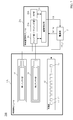
- FIG. 1 is a schematic configuration diagram of an illumination device 100 according to the first embodiment.
- FIG. 2 is a schematic configuration diagram of the antenna unit 11 according to the first embodiment.
- the illumination device 100 includes an illumination module 1, a wireless communication module 2, and a power supply unit 3, as shown in FIG.
- the power supply unit 3 may be included in the illumination module 1.
- the illumination module 1 includes an antenna unit 11 and an illumination unit 12.
- the antenna unit 11 includes, for example, an antenna substrate 111 and an antenna element unit 112.
- the antenna substrate 111 is a substrate formed as a thin film (film) made of a transparent material such as PET (polyethylene terephthalate), and has high light transmittance.
- the thickness of the antenna substrate 111 is preferably set such that light (particularly visible light) can be sufficiently transmitted in consideration of the material.
- the thickness of the antenna substrate 111 is preferably set to a thickness that can be bent or bent. For example, when the material of the antenna substrate 111 is PET, the thickness is preferably 100 ⁇ m or less.
- the antenna element portion 112 is configured by forming a conductor pattern (metal pattern) on the antenna substrate 111.
- the antenna element portion 112 functions as a pattern antenna by forming a predetermined conductor pattern on the antenna substrate 111.
- the antenna unit 11 may have a protective layer (for example, a protective film) that protects the conductor pattern on the antenna substrate 111.
- a protective layer for example, a protective film
- the antenna element portion 112 includes connection terminal portions 112a and 112i for electrically connecting to the wireless communication module 2, and antenna element portions 112b and 112c for constituting a loop antenna. 112d, 112e, 112f, 112g, and 112h.
- the lengths of the antenna element portions 112b to 112h are preferably substantially the same as the wavelength of the electromagnetic wave to be transmitted / received (the wavelength of the electromagnetic wave for which the antenna transmission / reception sensitivity is desired to be maximized).
- the antenna element portion 112 is not limited to the shape (pattern) shown in FIG. 2, and may have other shapes (for example, a shape constituting a dipole antenna) according to the antenna characteristics (transmission / reception characteristics) to be realized. , A shape having a meandering pattern, etc.).
- the antenna unit 11 is, for example, an elongated tube similar to a fluorescent lamp, and the inside thereof is installed in a hollow tube.
- the conductor pattern of the antenna element portion 112 may be formed by, for example, a lattice pattern. That is, the conductor pattern may be formed on the antenna substrate 111 so that a lattice pattern having a lattice width w is formed as in the enlarged view of the region R1 illustrated in FIG.
- the conductor pattern is formed on the antenna substrate 111 so that a lattice pattern having a lattice width w satisfying both the inequalities is formed.
- the illumination light diffracts the lattice pattern and is not blocked, it is possible to appropriately suppress a decrease in transmittance due to the illumination light passing through the antenna element portion 112.
- the lattice pattern may have substantially the same vertical width and horizontal width, or may have a different vertical width and horizontal width.
- width w1 and the horizontal width w2 of the lattice pattern are w1 ⁇ _R w1> ⁇ _L w2 ⁇ _R w2> ⁇ _L
- the conductor pattern may be formed on the antenna substrate 111 so that a lattice pattern satisfying the above condition is formed.
- the lattice pattern is not limited to those formed by metal thin wires (conductor patterns) orthogonal to each other (a pattern in which the unit pattern of the lattice pattern is a square or rectangular shape).
- a plurality of fine metal wires (conductor patterns) may be formed on the antenna substrate 111 so as to cross each other diagonally. That is, a plurality of fine metal wires (conductor patterns) may be formed on the antenna substrate 111 so that the unit pattern of the lattice pattern has a rhombus shape. Further, a plurality of fine metal wires (conductor patterns) are formed on the antenna substrate 111 so that the unit pattern of the unit pattern of the lattice pattern has another shape (for example, a hexagonal shape or a random shape). It may be.
- a plurality of fine metal wires may be formed on the antenna substrate 111 so as to satisfy the above.
- the distance wa may be an average value between adjacent fine metal wires in a plurality of fine metal wires (conductor pattern).
- the illumination unit 12 includes n (n: natural number) LED elements L1, L2,..., Ln as shown in FIG.
- the n LED elements L1 to Ln are connected in series on a printed circuit board, for example, and the light emission control of the n LED elements L1 to Ln is performed by the DC voltage DC_L supplied from the power supply unit 3 to the illumination unit 12. Is executed.
- the illumination unit 12 is, for example, an elongated tube similar to a fluorescent lamp, and the inside thereof is installed in a hollow tube.
- the illumination unit 12 is connected to the power supply unit 3, and the voltage DC_L is supplied from the power supply unit 3. The n LED elements of the illumination unit 12 are driven by the voltage DC_L from the power supply unit 3.
- the wireless communication module 2 includes a matching unit 21, an RF unit 22, and a communication control unit 23.
- the matching unit 21 includes a circuit (impedance adjustment circuit) that performs impedance adjustment.
- the impedance adjustment circuit of the matching unit 21 is connected to the antenna element unit 112 of the antenna unit 11 and performs impedance adjustment.
- the matching unit 21 may include a transmission impedance adjustment circuit and a reception impedance adjustment circuit.
- the matching unit 21 may include a circuit in which a transmission impedance adjustment circuit and a reception impedance adjustment circuit are shared.
- the matching unit 21 outputs the signal after impedance adjustment to the RF unit 22 when the antenna unit 11 functions as a receiving antenna.
- the matching unit 21 inputs a signal from the RF unit 22, performs impedance adjustment on the input signal, and transmits the signal after impedance adjustment to the antenna unit. 11 is output.
- the RF unit 22 includes an antenna transmission processing unit (for example, an antenna transmission processing circuit) and an antenna reception processing unit (for example, an antenna reception processing circuit).
- the RF unit 22 inputs a command signal (control signal) from the communication control unit 23 and executes processing based on the command signal (control signal).
- the RF unit 22 When the antenna unit 11 functions as a reception antenna, the RF unit 22 operates an antenna reception processing unit (for example, an antenna reception processing circuit) and performs an impedance adjustment signal output from the matching unit 21. Then, antenna reception processing (for example, processing including RF demodulation processing) is executed. Then, the RF unit 22 outputs a signal (information) acquired by antenna reception processing (for example, RF demodulation processing) to the communication control unit 23.
- antenna reception processing for example, processing including RF demodulation processing
- the RF unit 22 outputs a signal (information) acquired by antenna reception processing (for example, RF demodulation processing) to the communication control unit 23.
- the RF unit 22 operates an antenna transmission processing unit (for example, an antenna transmission processing circuit).
- the signal (information) output from the communication control unit 23 is RF-modulated, and the RF-modulated signal is output to the matching unit 21.
- the communication control unit 23 controls each functional unit of the wireless communication module.
- the communication control unit 23 is realized by, for example, a microprocessor.
- the communication control unit 23 is connected to the RF unit 22 and outputs a control signal to the RF unit 22 and information (signal) for performing RF modulation and antenna transmission.
- the communication control unit 23 detects that a radio wave is being transmitted from a lighting device other than its own device based on a signal from the RF unit 22, in order to prevent interference, collisions, etc.
- a control signal for stopping the RF modulation processing of the device itself may be output to the RF unit 22.
- the communication control unit 23 generates a power control signal Ctl based on a signal from the RF unit 22 and outputs the generated power control signal Ctl to the power supply unit 3.
- the power supply unit 3 is connected to an AC power supply (not shown) and functions as a constant voltage source for the outside by converting AC current (or AC voltage) into DC current (or AC voltage).
- the power supply unit 3 is connected to the wireless communication module 2 and functions as a direct current power source that supplies a constant voltage DC_W to the wireless communication module 2.
- the power supply unit 3 is connected to the illumination unit 12 of the illumination module 1 and functions as a direct current power source that supplies the voltage DC_L to the illumination unit 12.
- the power supply unit 3 inputs a power supply control signal Ctl output from the communication control unit 23.
- the power supply unit 3 adjusts the value of the voltage DC_L supplied (output) to the illumination unit 12 of the illumination module 1 based on the power supply control signal Ctl.
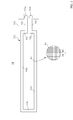
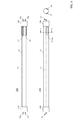
- FIG. 3 is a plan view and a side view of the illumination device 100 according to the first embodiment.
- FIG. 4 is an enlarged view of a part of the illumination device 100 according to the first embodiment. Specifically, FIG. 4 is an enlarged view of a portion including the lighting tube 13 and the lighting tube terminal portion 14a of the lighting device 100, and the upper view of FIG. 4 is a plan view, and the lower left of FIG. The figure is a sectional view taken along the line AA, and the lower right figure in FIG. 4 is a sectional view taken along the line BB.
- the illumination device 100 is provided in an illumination tube 13 having a hollow inside, illumination tube terminal portions 14a and 14b provided at both ends of the illumination tube 13, and an illumination tube terminal portion 14a. Electrodes 15a and 15b, and electrodes 16a and 16b provided on the illumination tube terminal portion 14b. And as shown in FIG. 3, the antenna part 11 and the illumination part 12 are installed in the inside of the tube 13 for illumination.
- the wireless communication module 2 and the power supply unit 3 are provided inside the illumination tube terminal unit 14a.
- the wireless communication module 2 is a module that can be attached to and detached from the illumination module 1.
- a space for housing the wireless communication module 2 is provided in the illumination tube terminal portion 14 a, and the wireless communication module 2 is illuminated as shown in FIG. 4.
- the module 1 is mounted in the illumination tube terminal portion 14a.
- FIG. 5 shows a schematic configuration diagram of the wireless communication module 2.
- the wireless communication module 2 has a spring connection terminal 24.
- the wireless communication module 2 has five spring connection terminals 24a to 24e.
- the spring-type connection terminal 24a of the wireless communication module 2 is a power supply terminal and is a terminal for receiving supply of the DC voltage DC_W from the power supply unit 3.
- the spring-type connection terminal 24 b of the wireless communication module 2 is a GND terminal and is a terminal for connecting to the GND of the power supply unit 3.
- the spring-type connection terminal 24 e of the wireless communication module 2 is a control signal terminal, and is a connection terminal for transmitting the power control signal Ctl from the wireless communication module 2 to the power supply unit 3.
- the spring connection terminals 24c and 24d of the wireless communication module 2 are terminals for connecting to the antenna unit 11, and as shown in FIG. 4, the spring connection terminals 24c and 24d are respectively connected to the antenna unit 11. This is a terminal for connecting to the connection terminal portions 112a and 112i of the antenna element portion 112.
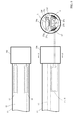
- FIG. 6 is a diagram for explaining the spring-type connection terminal 24 of the wireless communication module 2.
- FIG. 6 is a diagram corresponding to the lower left diagram of FIG. 4 in which a part of the illumination tube terminal portion 14a, the antenna portion 11, and the wireless communication module 2 are extracted and shown. It is the figure which showed typically the condition which attaches the module 2 for radio
- FIG. 6 shows a state in which the wireless communication module 2 is mounted in the illumination tube terminal portion 14a by moving the wireless communication module 2 from left to right.
- the spring-type connection terminal 24 of the wireless communication module 2 includes a conductor contact portion and a conductor elastic member (for example, a spring).
- the illumination tube terminal portion 14 a is provided with a triangular protrusion in the cross section.
- the wireless communication module 2 When the wireless communication module 2 is moved from left to right, the wireless communication module 2 is When passing through the slope of the illumination tube terminal portion 14a, the elastic member of the spring-type connection terminal 24 of the wireless communication module 2 contracts (for example, see the middle diagram of FIG. 6). Then, after the wireless communication module 2 passes through the slope of the illumination tube terminal portion 14a, the elastic member of the spring-type connection terminal 24 of the wireless communication module 2 expands as shown in the lower diagram of FIG. It will be in the state electrically connected with 11 connection terminal parts.
- the spring connection terminal 24a which is a power supply terminal, is connected to a terminal for supplying the DC voltage DC_W from the power supply unit 3 directly or via wiring.
- the spring-type connection terminal 24b which is a GND terminal, to the GND terminal of the power supply unit 3 directly or through wiring.
- the spring-type connection terminal 24e which is a control signal terminal, is connected to the connection terminal for receiving the power control signal Ctl of the power supply unit 3 directly or through wiring. be able to.
- connection terminal portions 112a and 112i of the antenna portion 11 are provided on the highly flexible sheet-like antenna substrate 111, normally, the connection terminals of the detachable wireless communication module are surely electrically connected. It is difficult to do.
- the wireless communication module 2 Since the wireless communication module 2 has the spring connection terminals 24 as described above, the wireless communication module 2 is provided on the highly flexible sheet-like antenna substrate 111 by using the elastic force of the spring connection terminals 24.
- the connection terminal portions 112a and 112i of the antenna portion 11 can be reliably connected electrically.
- the illumination device 100 houses the antenna unit 11 that is a pattern antenna formed on a film substrate with high light transmittance and the illumination unit 12 in the illumination tube 13 of the illumination module 1. Thus, the appearance of the lighting device is not impaired.
- the antenna part 11 which is a pattern antenna formed on the film substrate with high light transmittance is installed at the end in the illumination tube 13 of the illumination module 1, illumination is performed.
- the light emitted from the section 12 is hardly shielded or obstructed.
- w ⁇ _R w> ⁇ _L When a pattern antenna in which a conductor pattern is formed on the antenna substrate 111 is employed so that a lattice pattern having a lattice width w satisfying both the inequalities is formed, the illumination light from the illumination unit 12 Since the pattern is diffracted and is not blocked, it is possible to more appropriately suppress the decrease in transmittance due to the illumination light passing through the antenna element portion 112.
- the illumination module 1 has a structure in which the detachable wireless communication module 2 can be attached. Therefore, by attaching the wireless communication module 2 to the illumination module 1, It can be easily extended to a lighting device with a wireless communication function.
- the illumination module 1 is equipped with the antenna unit 11 and the illumination unit 12, and when it is desired to add a wireless communication function, the detachable wireless communication module 2 is attached, so that the illumination can be easily performed.
- a wireless communication function can be added to the module 1.
- the antenna unit 11 can be arranged at a position where it is easy to transmit and receive electromagnetic waves to be transmitted and received. For example, as shown in FIG. 3, by installing the illumination module 1 in which the antenna unit 11 is disposed below the illumination unit 12, for example, on a ceiling or the like, the antenna unit 11 can transmit and receive electromagnetic waves. Can be wide. As a result, the antenna transmission / reception sensitivity is increased, and as a result, the illumination device 100 can perform highly reliable wireless communication.
- the lighting performance of the lighting device can be ensured and reliable wireless communication can be performed without deteriorating the appearance of the lighting device.
- FIG. 7 is a schematic configuration diagram of an illumination device 200 according to the second embodiment.
- the illumination module 1 of the illumination device 100 of the first embodiment has a configuration having one antenna (antenna unit 11).
- the illumination module 1A of the illumination device 200 of the second embodiment has two antennas ( A structure having a first antenna portion 17 and a second antenna portion 18).
- the illumination device 200 of the second embodiment has a configuration in which the wireless communication module 2 of the first embodiment is replaced with a wireless communication module 2A.
- the first antenna unit 17 and the second antenna unit 18, which are the two antennas of the illumination module 1A, are basically the same as the antenna unit 11 of the first embodiment. However, you may make it change the magnitude
- the wavelength of light emitted from the illumination portion 12 of the illumination module 1A is ⁇ _L
- the antenna portion 11 If the wavelength of electromagnetic waves to be transmitted and received is ⁇ _R, w ⁇ _R w> ⁇ _L
- the conductor pattern may be formed on the antenna substrate so that a lattice-shaped pattern having a lattice width w satisfying both the inequalities is formed.
- the wireless communication module 2A includes a switch unit 26, a matching unit 21A, an RF unit 22A, and a communication control unit 23A.
- the switch unit 26 is connected to the first antenna unit 17 and the second antenna unit 18.
- the switch unit 26 also receives a control signal from the communication control unit 23A.
- the switch unit 26 selects the antenna having the higher antenna sensitivity of the first antenna unit 17 and the second antenna unit 18 based on the control signal from the communication control unit 23A.
- the antenna is connected to the matching unit 21A.
- the switch unit 26 has an output of the matching unit 21A with the higher antenna sensitivity of the first antenna unit 17 and the second antenna unit 18 based on the control signal from the communication control unit 23A. To be input to the antenna.
- the switch unit 26 When receiving the antenna, the switch unit 26 receives the output from the first antenna unit 17 and the second antenna unit 18 according to the ratio (for example, the internal division ratio) specified by the control signal from the communication control unit 23A. May be combined (for example, combining by internal ratio), and the combined output may be output to the matching unit 21A. In addition, when transmitting the antenna, the switch unit 26 outputs the output from the matching unit 21A to the first antenna unit 17 and the second antenna according to the ratio (for example, internal division ratio) specified by the control signal from the communication control unit 23A.
- the antenna unit 18 may be input in a distributed manner.
- the matching unit 21A has the same configuration and function as the matching unit 21 of the first embodiment.
- the matching unit 21 ⁇ / b> A performs impedance adjustment when connected to the first antenna unit 17 and / or the second antenna unit 18 via the switch unit 26.
- the RF unit 22A basically has the same function as the RF unit 22 of the first embodiment.
- the communication control unit 23A basically has the same function as the communication control unit 23 of the first embodiment.
- the communication control unit 23A generates a control signal for controlling the switch unit 26 based on the output from the RF unit 22A, and outputs the generated control signal to the switch unit 26.
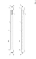
- FIG. 8 is a plan view, a side view, and a cross-sectional view taken along the line CC of the illumination device 200 according to the second embodiment.
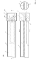
- FIG. 9 is an enlarged view of a part of the illumination device 200 according to the second embodiment. Specifically, FIG. 9 is an enlarged view of a portion including the lighting tube 13 and the lighting tube terminal portion 14a of the lighting device 200.
- the upper view of FIG. 9 is a plan view, and the lower left of FIG. The figure is a side view, and the lower right figure in FIG. 9 is a sectional view taken along the line DD.
- the illumination device 200 is provided in the illumination tube 13 having a hollow inside, illumination tube terminal portions 14a and 14b provided at both ends of the illumination tube 13, and the illumination tube terminal portion 14a. Electrodes 15a and 15b, and electrodes 16a and 16b provided on the illumination tube terminal portion 14b.
- the 1st antenna part 17, the 2nd antenna part 18, and the illumination part 12 are installed in the inside of the tube 13 for illumination.
- the 1st antenna part 17 and the 2nd antenna part 18 can be curved, as shown in FIG. 8, it is installed along the inner wall of the tube 13 for illumination.
- the first antenna unit 17 and the second antenna unit 18 are arranged at positions where the illumination light from the illumination unit 12 is difficult to block, the high transmittance of the illumination light from the illumination unit 12 is achieved. Can be maintained.
- the wireless communication module 2A and the power supply unit 3 are provided inside the illumination tube terminal unit 14a.
- the wireless communication module 2A is a module that can be attached to and detached from the illumination module 1 as in the first embodiment.
- the illumination tube terminal portion 14a is provided with a space for housing the wireless communication module 2A, and the wireless communication module 2A is mounted in the illumination tube terminal portion 14a of the illumination module 1A.
- the wireless communication module 2A has seven spring-type connection terminals 25 (25a to 25g).
- the wireless communication module 2A can be attached to and detached from the illumination module 1A.
- the illumination tube terminal portion 14a has a cross section shown in the lower right diagram of FIG. A space for storing the wireless communication module 2A is provided.
- the connection terminals of the wireless communication module 2A are connected to the first antenna unit 17, the second antenna unit 18, and the power supply unit 3 by the same mechanism as shown in FIG. Are electrically connected to the corresponding connection terminals.
- the spring-type connection terminals 25a and 25b are connected to the two connection terminal portions of the antenna element portion of the first antenna portion 17, respectively.
- the spring-type connection terminals 25c and 25d are connected to the two connection terminal portions of the antenna element portion of the second antenna portion 18, respectively.
- the spring-type connection terminal 25e which is a power supply terminal, is connected to a terminal for supplying the DC voltage DC_W from the power supply unit 3 directly or via wiring.
- connection terminal portions of 17 and the second antenna portion 18 are also arranged in a curved state.
- the wireless communication module 2A includes the spring connection terminals 25 (25a to 25g), the wireless communication module 2A is provided on a highly flexible sheet-like antenna substrate by using the elastic force of the spring connection terminals 25. Even if the connection terminal portions of the first antenna portion 17 and the second antenna portion 18 are curved as described above, they can be reliably electrically connected.
- the first antenna unit 17 and the second antenna unit 18 can be arranged at various positions of the lighting tube 13, and the first antenna unit 17 and the second antenna unit 18 are connected to each other.
- the terminal portion can be reliably connected to the spring-type connection terminal 25 (25a to 25g) of the detachable wireless communication module 2A.
- the illuminating device 200 includes the first antenna unit 17 and the second antenna unit which are pattern antennas formed on the film substrate with high light transmittance in the illumination tube 13 of the illumination module 1A. 18 and the illuminating unit 12 are housed, so that the appearance of the lighting device is not impaired.
- the 1st antenna part 17 and the 2nd antenna part 18 which are pattern antennas formed on the film substrate with a high light transmittance are made into the end in the tube 13 for illumination of the module 1A for illumination. Since it is installed in the unit, the light emitted from the illumination unit 12 is hardly shielded or obstructed.
- the illumination light from the illumination unit 12 is Since the illumination light passes through the antenna element portions of the first antenna portion 17 and the second antenna portion 18, a decrease in transmittance can be further appropriately suppressed.
- the illumination module 1A has a structure in which the detachable wireless communication module 2A can be attached. Therefore, by attaching the wireless communication module 2A to the illumination module 1A. It can be easily extended to a lighting device with a wireless communication function.
- the wireless communication module is expensive, it is not preferable to install the wireless communication module on all the lighting modules 1A from the beginning because the cost increases. Therefore, the first module 17, the second antenna unit 18, and the illumination unit 12 are mounted on the illumination module 1 ⁇ / b> A, and can be attached and detached when a wireless communication function is to be added. By mounting 2A, a wireless communication function can be easily added to the illumination module 1A.
- the first antenna unit 17 and the second antenna unit 18 can be disposed at positions where electromagnetic waves to be transmitted and received can be easily transmitted and received.
- the range in which the first antenna unit 17 and the second antenna unit 18 can transmit and receive electromagnetic waves can be widened.
- the lighting device 200 uses two (plural) antennas, antenna transmission / reception sensitivity can be further improved by antenna diversity. Thereby, in the illuminating device 200, highly reliable wireless communication can be performed.
- the illumination performance of the lighting device can be ensured without damaging the appearance of the lighting device, and highly reliable wireless communication can be performed.
- the lighting device of this modification has the same configuration as the lighting device 200 of the second embodiment.
- the illumination device of this modification is characterized in that the installation positions of the first antenna unit 17 and the second antenna unit 18 are arranged at positions that take into account the reflector of the illumination device.
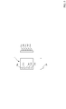
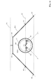
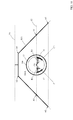
- FIG. 10 is a schematic cross-sectional view of the illumination device 200A of the present modification and the illumination reflector RF1.
- FIG. 10 is a schematic cross-sectional view of the lighting device 200A and the lighting reflector RF1 cut along a line corresponding to the line DD in FIG.
- the power supply unit 3, the wireless communication module 2A, and the like are omitted.
- a plane P1 is a plane (for example, a plane corresponding to a ceiling or a side wall) on which the illumination reflector RF1 is attached.
- the illuminating reflector RF1 when the central point C0 of the illuminating tube 13 is regarded as a point light source, the illuminating reflector RF1 emits illumination light over a wide range opposite to the plane on which the illuminating reflector RF1 is attached. In many cases, the shape is set so as to be irradiated.
- the electromagnetic wave to be received be disposed directly or directly at a position that is reflected by the lighting reflector RF1 and reaches the first antenna portion 17 and the second antenna portion 18 (electromagnetic wave). The same applies when transmitting from the first antenna unit 17 and the second antenna unit 18).
- the first antenna unit 17 is arranged so that at least a part thereof is included in the region R2 of FIG. 10, and the second antenna unit 18 has at least a part of FIG. It is preferable to arrange so as to be included in the region R3.
- the regions R2 and R3 are defined as follows.
- the region R2 includes (1) a plane P2 that passes through the center point C0 of the illumination tube 13 and is parallel to the plane P1 to which the illumination reflector RF1 is attached. ) A space (region) defined by a line C0-C1 passing through the center point C0 of the illumination tube 13 and parallel to the side A1-A2 of the illumination reflector RF1, and (3) the inner wall of the illumination tube 13. is there.
- the region R3 includes (1) a plane P2 passing through the center point C0 of the illumination tube 13 and parallel to the plane P1 to which the illumination reflector RF1 is attached, and (2) illumination.
- This is a space (region) defined by a line C0-C2 passing through the center point C0 of the illuminating tube 13 and parallel to the sides A4-A5 of the illuminating reflector RF1, and (3) the inner wall of the illuminating tube 13.
- a line C0-C1 for defining the region R2 is a line parallel to the tangent to the illumination reflector RF1 at the point A3 (intersection of the plane P2 and the side A1-A2) in FIG. 10, and the center point C0. It may be a line passing through.
- a line C0-C2 for defining the region R3 is a line parallel to the tangent of the illumination reflector RF1 at the point A6 (intersection of the plane P2 and the side A4-A5) in FIG. It may be a line passing through.
- the plane P1 to which the illumination reflector RF1 is attached is an approximate plane (for example, a predetermined region centered on the position to which the illumination reflector RF1 is attached) when the surface to which the illumination reflector RF1 is attached is not a plane. (Virtual plane obtained by averaging).
- FIG. 11 is a diagram in which the first antenna unit 17 and the second antenna unit 18 are superimposed on FIG.
- most of the first antenna unit 17 is disposed in the region R2
- most of the second antenna unit 18 is disposed in the region R3.
- the electromagnetic wave to be received is reflected directly or by the reflector for illumination RF1 and reaches the first antenna unit 17 and the second antenna unit 18 efficiently.
- the antenna sensitivity can be further improved in the lighting device 200A.
- the first antenna is considered in consideration of the positional relationship with the reflector for illumination so that the sensitivity in the direction is increased. It is preferable to determine the arrangement of the unit 17 and the second antenna unit 18.
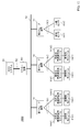
- FIG. 12 is a schematic configuration diagram of an illumination control system 3000 according to the third embodiment.
- the lighting control system 3000 includes a master device M1, a first slave device S1, a second slave device S2, and a third slave device S3 connected to a network N1 (wired network N1).
- the wired network N1 is, for example, a wired network using a dedicated line, or a network (for example, a power line carrier communication network (PLC network)) that performs communication by modulating and superimposing a signal on a power line.
- PLC network power line carrier communication network
- the illumination control system 3000 is connected to a detachable wireless communication module WM11 and a detachable wireless communication module WM12 that are connected to the first slave device S1 via a wireless communication network W1. And an illumination module LM12.
- the illumination control system 3000 is connected to a detachable wireless communication module WM21 and a detachable wireless communication module WM22 that are connected to the second slave device S2 via a wireless communication network W2. And an illumination module LM22.
- the illumination control system 3000 includes an illuminance sensor SS31 connected to the third slave device S3 by a wireless communication network W3, and a human sensor SS32.
- the lighting control system 3000 includes one master device and three slave devices.
- the lighting control system 3000 is not limited to this configuration, and a plurality of master devices. And a plurality of slave devices.
- the removable wireless communication modules WM11, WM12, WM21, and WM22 are the same as the wireless communication module 2 or 2A described in the above embodiment.
- the illumination modules LM11 and LM12 are the same as the illumination module 1 or 1A described in the above embodiment.
- illustration is abbreviate
- the illuminance detected by the illuminance sensor SS31 is in a low (dark) state
- the human sensor SS32 detects a person
- the illumination module 12 of the illumination module LM11 is turned off.
- the control for lighting is described below.
- the illuminance sensor SS31 transmits a signal including information indicating that the illuminance detected by the illuminance sensor SS31 is low (dark) to the third slave device S3 via the wireless communication network W3.
- the third slave device S3 transmits a signal including information acquired from the illuminance sensor SS31 via the wireless communication network W3 to the master device M1 via the wired network N1.
- the master device M1 acquires information about the illuminance detected by the illuminance sensor SS31 received via the wired network N1 from the third slave device S3, and holds the information.
- the human sensor SS32 when the human sensor SS32 detects a person, the human sensor SS32 transmits a signal including information indicating that the person has been detected to the third slave device S3 via the wireless communication network W3.
- the third slave device S3 transmits information received from the human sensor SS32 via the wireless communication network W3 (information indicating that a person has been detected) to the master device M1 via the wired network N1.
- the master device M1 acquires information indicating that a person has been detected by the human sensor SS32 based on a signal received from the third slave device S3 via the wired network N1. And the master apparatus M1 transmits the signal which instruct
- the first slave device S1 receives a signal transmitted from the master device M1 via the wired network N1, and transmits the received signal to the removable wireless communication module WM11 via the wireless communication network W1.
- the detachable wireless communication module WM11 receives a signal from the first slave device S1 via the wireless communication network W1. Specifically, the radio signal from the first slave device S1 is received by the antenna unit 11 (or the first antenna unit 17 and / or the second antenna unit 18) of the illumination module LM11. Then, processing by the matching unit 21 (or 21A) and the RF unit 22 (or 22A) of the removable wireless communication module WM11 is performed on the received signal. Thereby, the communication control unit 23 (or 23A) of the removable wireless communication module WM11 acquires a signal instructing lighting of the illumination unit 12 of the illumination module LM11.
- the communication control unit 23 uses a voltage that the power supply unit 3 supplies to the illumination unit 12 as a predetermined voltage (a predetermined dimming rate) that can turn on the LED elements L1 to Ln of the illumination unit 12.
- a power supply control signal Ctl instructing that the voltage is to be realized) is output to the power supply unit 3.
- the illumination unit 12 of the illumination module LM11 is turned on.
- the communication control unit 23 (or 23A) of the removable wireless communication module WM11 transmits a signal including information on the power consumed when the illumination unit 12 of the illumination module LM11 is turned on to the antenna of the illumination module LM11.
- the unit 11 (or the first antenna unit 17 and / or the second antenna unit 18) may be controlled so as to be transmitted to the first slave device S1 via the wireless communication network W1.
- the first slave device S1 receives the signal transmitted from the removable wireless communication module WM11, and transmits the received signal to the master device M1 via the wired network N1.
- the master device M1 can grasp the amount of power consumed by the lighting module LM11 being lit from the signal received from the first slave device S1 via the wired network N1.
- the lighting control system 3000 by performing such processing, it is possible to grasp the power consumption acquired from each slave device and perform control such as turning off unnecessary lighting in order to realize energy saving.
- the master device M1 may be connected to the host system H1 via the network N2, and the information collected by the master device M1 may be transmitted to the host system H1.
- the host system H1 may instruct the master apparatus M1 to perform predetermined control based on the collected information.
- the detachable wireless communication module and the illumination module have been described for the case where the wireless communication is performed only with the slave device, but the present invention is not limited to this, and the detachable wireless communication module and the illumination module are not limited thereto. You may make it communicate by radio
- the illumination control system can be configured using the removable wireless communication module and the illumination module corresponding to the illumination devices 100 and 200 of the first and second embodiments. it can.
- the lighting control system 3000 only the slave device needs to have the communication functions of both the wired network and the wireless communication network, and the removable wireless communication module and the lighting module need only have the wireless communication function. . Thereby, in the lighting control system 3000, the total cost can be reduced when the system is constructed.
- the wireless communication module can be attached to and detached from the lighting module, the cost of the lighting module can be reduced. And since it is only necessary to load a detachable wireless communication module only to the illumination module to which a wireless communication function is to be added, it is possible to easily construct the illumination control system 3000 having flexibility and high expandability. Can do.
- the said embodiment demonstrated the case where the power supply part 3 was arrange
- the power supply unit 3 may be disposed on the back side of the illumination unit 12 (for example, on the side opposite to the side on which the antenna unit 11 is disposed in FIGS. 3 and 4).
- the power supply part 3 may be arrange
- the wireless communication module 2 includes the antenna unit 11 (or the first antenna unit 17 and the second antenna unit 18) and the power supply unit 3 by the spring-type connection terminals 24 (or 25).
- each terminal of the wireless communication module 2 (or 2A) is connected to the antenna unit 11 (or the first antenna unit 17, the second antenna unit 18) and the power supply unit 3 by a connector. It may be connected to a terminal. Also in this case, it is preferable to provide the connector for connection in the tube terminal part 14a for illumination.
- the spatial diversity antenna is configured using two antennas.
- the present invention is not limited to this.
- a frequency diversity antenna using a plurality of antennas is used. You may make it comprise.
- the number of antennas is not limited to two, and more antennas may be used.
- circuit may be realized in whole or in part by hardware, software, or a mixture of hardware and software.
Landscapes
- Engineering & Computer Science (AREA)
- General Engineering & Computer Science (AREA)
- Physics & Mathematics (AREA)
- Microelectronics & Electronic Packaging (AREA)
- Optics & Photonics (AREA)
- Computer Networks & Wireless Communication (AREA)
- Circuit Arrangement For Electric Light Sources In General (AREA)
- Arrangement Of Elements, Cooling, Sealing, Or The Like Of Lighting Devices (AREA)
- Non-Portable Lighting Devices Or Systems Thereof (AREA)
Applications Claiming Priority (2)
| Application Number | Priority Date | Filing Date | Title |
|---|---|---|---|
| JP2013201881A JP6166633B2 (ja) | 2013-09-27 | 2013-09-27 | 照明用モジュール、無線通信用モジュール、照明装置、および、照明制御システム |
| JP2013-201881 | 2013-09-27 |
Publications (1)
| Publication Number | Publication Date |
|---|---|
| WO2015045892A1 true WO2015045892A1 (ja) | 2015-04-02 |
Family
ID=52743035
Family Applications (1)
| Application Number | Title | Priority Date | Filing Date |
|---|---|---|---|
| PCT/JP2014/074144 Ceased WO2015045892A1 (ja) | 2013-09-27 | 2014-09-11 | 照明用モジュール、無線通信用モジュール、照明装置、および、照明制御システム |
Country Status (2)
| Country | Link |
|---|---|
| JP (1) | JP6166633B2 (enExample) |
| WO (1) | WO2015045892A1 (enExample) |
Cited By (3)
| Publication number | Priority date | Publication date | Assignee | Title |
|---|---|---|---|---|
| CN108551703A (zh) * | 2018-03-13 | 2018-09-18 | 深圳市安拓浦科技有限公司 | 一种一体化led灯天线 |
| GB2576354A (en) * | 2018-08-10 | 2020-02-19 | Tridonic Gmbh & Co Kg | Modular wireless interface for a lighting device |
| WO2023151206A1 (zh) * | 2022-02-09 | 2023-08-17 | 厦门普为光电科技有限公司 | 具有隐藏式天线的照明装置及其制造方法 |
Families Citing this family (11)
| Publication number | Priority date | Publication date | Assignee | Title |
|---|---|---|---|---|
| JP6579511B2 (ja) * | 2015-05-11 | 2019-09-25 | パナソニックIpマネジメント株式会社 | 光源ユニットおよびそれを備えた照明器具 |
| JP6774171B2 (ja) * | 2015-08-03 | 2020-10-21 | アイリスオーヤマ株式会社 | 発光ユニットおよび発光ユニットを備える照明装置 |
| JP6675089B2 (ja) * | 2015-12-10 | 2020-04-01 | パナソニックIpマネジメント株式会社 | 照明器具 |
| JP6692048B2 (ja) | 2016-04-25 | 2020-05-13 | パナソニックIpマネジメント株式会社 | 照明器具及び照明システム |
| JP6967748B2 (ja) * | 2017-02-24 | 2021-11-17 | パナソニックIpマネジメント株式会社 | 照明器具及び照明システム |
| JP7031839B2 (ja) * | 2017-06-28 | 2022-03-08 | アイリスオーヤマ株式会社 | 照明用ランプ |
| JP6955258B2 (ja) * | 2017-11-17 | 2021-10-27 | アイリスオーヤマ株式会社 | 照明装置用の通信ユニット及び照明装置 |
| JP7187948B2 (ja) * | 2018-09-28 | 2022-12-13 | 三菱電機株式会社 | 無線ユニットおよび照明器具 |
| JP6725949B2 (ja) * | 2019-08-22 | 2020-07-22 | アイリスオーヤマ株式会社 | 発光ユニットおよび発光ユニットを備える照明装置 |
| JP7551095B2 (ja) * | 2020-03-31 | 2024-09-17 | アイリスオーヤマ株式会社 | 照明装置 |
| JP7617546B2 (ja) * | 2020-04-20 | 2025-01-20 | パナソニックIpマネジメント株式会社 | 照明器具 |
Citations (4)
| Publication number | Priority date | Publication date | Assignee | Title |
|---|---|---|---|---|
| JP2012529143A (ja) * | 2009-06-05 | 2012-11-15 | コーニンクレッカ フィリップス エレクトロニクス エヌ ヴィ | 組み込みrfアンテナを備える照明装置 |
| JP2012227021A (ja) * | 2011-04-20 | 2012-11-15 | Panasonic Corp | 照明用光源 |
| US20130155664A1 (en) * | 2011-12-19 | 2013-06-20 | Lg Innotek Co., Ltd. | Led lighting apparatus |
| JP2013140751A (ja) * | 2012-01-06 | 2013-07-18 | Sony Corp | 電球型光源装置 |
Family Cites Families (1)
| Publication number | Priority date | Publication date | Assignee | Title |
|---|---|---|---|---|
| JP2004096608A (ja) * | 2002-09-03 | 2004-03-25 | Matsushita Electric Ind Co Ltd | 中継用無線機器 |
-
2013
- 2013-09-27 JP JP2013201881A patent/JP6166633B2/ja not_active Expired - Fee Related
-
2014
- 2014-09-11 WO PCT/JP2014/074144 patent/WO2015045892A1/ja not_active Ceased
Patent Citations (4)
| Publication number | Priority date | Publication date | Assignee | Title |
|---|---|---|---|---|
| JP2012529143A (ja) * | 2009-06-05 | 2012-11-15 | コーニンクレッカ フィリップス エレクトロニクス エヌ ヴィ | 組み込みrfアンテナを備える照明装置 |
| JP2012227021A (ja) * | 2011-04-20 | 2012-11-15 | Panasonic Corp | 照明用光源 |
| US20130155664A1 (en) * | 2011-12-19 | 2013-06-20 | Lg Innotek Co., Ltd. | Led lighting apparatus |
| JP2013140751A (ja) * | 2012-01-06 | 2013-07-18 | Sony Corp | 電球型光源装置 |
Cited By (5)
| Publication number | Priority date | Publication date | Assignee | Title |
|---|---|---|---|---|
| CN108551703A (zh) * | 2018-03-13 | 2018-09-18 | 深圳市安拓浦科技有限公司 | 一种一体化led灯天线 |
| CN108551703B (zh) * | 2018-03-13 | 2024-05-14 | 深圳市安拓浦科技有限公司 | 一种一体化led灯天线 |
| GB2576354A (en) * | 2018-08-10 | 2020-02-19 | Tridonic Gmbh & Co Kg | Modular wireless interface for a lighting device |
| GB2576354B (en) * | 2018-08-10 | 2022-07-06 | Tridonic Gmbh & Co Kg | Modular wireless interface for a lighting device |
| WO2023151206A1 (zh) * | 2022-02-09 | 2023-08-17 | 厦门普为光电科技有限公司 | 具有隐藏式天线的照明装置及其制造方法 |
Also Published As
| Publication number | Publication date |
|---|---|
| JP2015069774A (ja) | 2015-04-13 |
| JP6166633B2 (ja) | 2017-07-19 |
Similar Documents
| Publication | Publication Date | Title |
|---|---|---|
| JP6166633B2 (ja) | 照明用モジュール、無線通信用モジュール、照明装置、および、照明制御システム | |
| JP4366276B2 (ja) | 照明器具 | |
| JP2025111826A (ja) | 光源ユニット及び照明器具 | |
| JP6941812B2 (ja) | 照明器具及び照明制御システム | |
| JP2016157689A (ja) | 照明器具 | |
| US20190257486A1 (en) | Light fixture | |
| JP2016535958A (ja) | 無線送信機を備える照明器具 | |
| US12480647B2 (en) | Control module for a lighting fixture | |
| JP2015115287A (ja) | 照明用モジュール、無線通信用モジュール、照明装置、および、照明制御システム | |
| JP6484886B2 (ja) | 照明器具 | |
| JP2018125145A (ja) | 無線通信モジュール | |
| EP3804028B1 (en) | Stacked circuit boards within a lighting device | |
| JP6854467B2 (ja) | 照明駆動装置および照明器具 | |
| KR20120087396A (ko) | Led 조명장치 | |
| CN106151888B (zh) | 光源单元和包括该光源单元的照明器具 | |
| JP7584069B2 (ja) | 光源ユニット及び照明器具 | |
| JP2019110103A (ja) | 照明装置 | |
| JP2021182560A (ja) | 照明器具 | |
| JP6295074B2 (ja) | 無線通信装置、照明装置、照明用モジュール、無線通信用モジュール、および、照明制御システム | |
| JP6372750B2 (ja) | 照明器具 | |
| JP7565536B2 (ja) | 操作装置、配線器具 | |
| JP6138096B2 (ja) | 照明器具 | |
| JP2023101685A (ja) | 照明装置 | |
| JP2024025115A (ja) | 通信ユニット、通信装置、機器、照明器具、及び通信システム | |
| JP2016134272A (ja) | 操作装置 |
Legal Events
| Date | Code | Title | Description |
|---|---|---|---|
| 121 | Ep: the epo has been informed by wipo that ep was designated in this application |
Ref document number: 14850052 Country of ref document: EP Kind code of ref document: A1 |
|
| NENP | Non-entry into the national phase |
Ref country code: DE |
|
| 122 | Ep: pct application non-entry in european phase |
Ref document number: 14850052 Country of ref document: EP Kind code of ref document: A1 |