WO2015045685A1 - 空気調和装置 - Google Patents
空気調和装置 Download PDFInfo
- Publication number
- WO2015045685A1 WO2015045685A1 PCT/JP2014/071781 JP2014071781W WO2015045685A1 WO 2015045685 A1 WO2015045685 A1 WO 2015045685A1 JP 2014071781 W JP2014071781 W JP 2014071781W WO 2015045685 A1 WO2015045685 A1 WO 2015045685A1
- Authority
- WO
- WIPO (PCT)
- Prior art keywords
- refrigerant
- compressor
- heat exchanger
- valve
- way switching
- Prior art date
- Legal status (The legal status is an assumption and is not a legal conclusion. Google has not performed a legal analysis and makes no representation as to the accuracy of the status listed.)
- Ceased
Links
Images


Classifications
-
- F—MECHANICAL ENGINEERING; LIGHTING; HEATING; WEAPONS; BLASTING
- F25—REFRIGERATION OR COOLING; COMBINED HEATING AND REFRIGERATION SYSTEMS; HEAT PUMP SYSTEMS; MANUFACTURE OR STORAGE OF ICE; LIQUEFACTION SOLIDIFICATION OF GASES
- F25B—REFRIGERATION MACHINES, PLANTS OR SYSTEMS; COMBINED HEATING AND REFRIGERATION SYSTEMS; HEAT PUMP SYSTEMS
- F25B49/00—Arrangement or mounting of control or safety devices
- F25B49/02—Arrangement or mounting of control or safety devices for compression type machines, plants or systems
- F25B49/022—Compressor control arrangements
-
- F—MECHANICAL ENGINEERING; LIGHTING; HEATING; WEAPONS; BLASTING
- F25—REFRIGERATION OR COOLING; COMBINED HEATING AND REFRIGERATION SYSTEMS; HEAT PUMP SYSTEMS; MANUFACTURE OR STORAGE OF ICE; LIQUEFACTION SOLIDIFICATION OF GASES
- F25B—REFRIGERATION MACHINES, PLANTS OR SYSTEMS; COMBINED HEATING AND REFRIGERATION SYSTEMS; HEAT PUMP SYSTEMS
- F25B47/00—Arrangements for preventing or removing deposits or corrosion, not provided for in another subclass
- F25B47/02—Defrosting cycles
- F25B47/022—Defrosting cycles hot gas defrosting
- F25B47/025—Defrosting cycles hot gas defrosting by reversing the cycle
-
- F—MECHANICAL ENGINEERING; LIGHTING; HEATING; WEAPONS; BLASTING
- F25—REFRIGERATION OR COOLING; COMBINED HEATING AND REFRIGERATION SYSTEMS; HEAT PUMP SYSTEMS; MANUFACTURE OR STORAGE OF ICE; LIQUEFACTION SOLIDIFICATION OF GASES
- F25B—REFRIGERATION MACHINES, PLANTS OR SYSTEMS; COMBINED HEATING AND REFRIGERATION SYSTEMS; HEAT PUMP SYSTEMS
- F25B13/00—Compression machines, plants or systems, with reversible cycle
-
- F—MECHANICAL ENGINEERING; LIGHTING; HEATING; WEAPONS; BLASTING
- F25—REFRIGERATION OR COOLING; COMBINED HEATING AND REFRIGERATION SYSTEMS; HEAT PUMP SYSTEMS; MANUFACTURE OR STORAGE OF ICE; LIQUEFACTION SOLIDIFICATION OF GASES
- F25B—REFRIGERATION MACHINES, PLANTS OR SYSTEMS; COMBINED HEATING AND REFRIGERATION SYSTEMS; HEAT PUMP SYSTEMS
- F25B2600/00—Control issues
- F25B2600/02—Compressor control
- F25B2600/026—Compressor control by controlling unloaders
- F25B2600/0261—Compressor control by controlling unloaders external to the compressor
Definitions
- the present invention relates to an air conditioner.
- An air conditioner disclosed in Patent Document 1 is configured to discharge a compressor to a refrigerant circuit that connects a compressor, a four-way switching valve, an indoor heat exchanger, an electric expansion valve, and an outdoor heat exchanger.
- a bypass circuit is connected to bypass the side and the outlet side during heating operation of the outdoor heat exchanger. During the positive cycle defrosting operation, a part of the discharge gas is allowed to flow through the bypass circuit, thereby increasing the dryness of the refrigerant flowing through the outdoor heat exchanger and sucked into the compressor, and returning the liquid back to the compressor. Has been reduced.
- a bypass circuit (hereinafter referred to as a discharge-suction bypass circuit) disclosed in Patent Document 1 is provided between the discharge side of the compressor and the four-way switching valve, and between the outdoor heat exchanger and the four-way switching valve. Therefore, the length of the discharge-suction bypass circuit is long. Thus, when the length of the discharge-suction bypass circuit is long, there is a problem that the amount of refrigerant retained increases and the responsiveness of the refrigerant control becomes slow, so that the refrigerant controllability is lowered.
- an object of the present invention is to provide an air conditioner capable of suppressing an increase in the amount of refrigerant retained and suppressing a decrease in refrigerant controllability.
- An air conditioner includes a main refrigerant circuit and a discharge-suction bypass circuit.
- the main refrigerant circuit includes a compressor, a four-way switching valve, an indoor heat exchanger, a main valve, and an outdoor heat exchanger.
- the main refrigerant circuit is a positive cycle defrost that defrosts the outdoor heat exchanger while circulating the refrigerant in the order of the compressor, the four-way switching valve, the indoor heat exchanger, the main valve, the outdoor heat exchanger, and the four-way switching valve. It is possible to drive.
- the discharge-suction bypass circuit has an overheat valve.
- the discharge-suction bypass circuit is connected to the main refrigerant circuit so that the refrigerant can be bypassed from the discharge side of the compressor to the suction side of the compressor by opening the overheat valve during the positive cycle defrosting operation. ing.
- the junction of the refrigerant bypassed through the discharge-suction bypass circuit during the normal cycle defrosting operation and the refrigerant flowing through the main refrigerant circuit is the four-way switching valve and the suction part of the compressor. It is arranged between.
- the joining portion of the refrigerant bypassed through the discharge-suction bypass circuit and the refrigerant flowing through the main refrigerant circuit during the positive cycle defrosting operation includes the four-way switching valve and the compression It is arranged between the suction part of the machine. For this reason, the length of the discharge-suction bypass circuit can be shortened as compared with the case where the junction portion is disposed between the outdoor heat exchanger and the four-way switching valve.
- An air conditioner according to a second aspect of the present invention is the air conditioner according to the first aspect, wherein the junction is arranged immediately after exiting the four-way switching valve in the refrigerant flow direction during the normal cycle defrosting operation. ing. For this reason, it is possible to secure a distance from the junction part to the suction part of the compressor, and as a result, the mixing of the refrigerant flowing through the main refrigerant circuit and the refrigerant bypassed through the discharge-suction bypass circuit is promoted. Can do. In addition, since the distance from the joining portion to the suction portion of the compressor can be secured, it is possible to reduce the influence of stress generated in the discharge-suction bypass circuit due to the vibration of the compressor.
- An air conditioner according to a third aspect of the present invention is the air conditioner according to the first or second aspect, wherein the main refrigerant circuit is U-shaped as a pipe connecting the four-way switching valve and the suction portion of the compressor. Shaped trap tube. For this reason, since the distance from the four-way switching valve to the suction part of the compressor can be secured as compared with the case where the trap pipe is not included as the pipe, the merging part is arranged upstream of the trap pipe. If so, the mixing of the refrigerant flowing through the main refrigerant circuit and the refrigerant bypassed through the discharge-suction bypass circuit can be promoted.
- the air conditioner according to the fourth aspect of the present invention is the air conditioner according to any one of the first to third aspects, wherein the main refrigerant circuit can perform a reverse cycle defrosting operation.
- the reverse cycle defrosting operation switches the state of the four-way switching valve from the state of the normal cycle defrosting operation, so that the compressor, the four-way switching valve, the outdoor heat exchanger, the main valve, the indoor heat exchanger, the four-way switching In this operation, the outdoor heat exchanger is defrosted while circulating the refrigerant in the order of the valves.
- the refrigerant is circulated through the discharge-suction bypass circuit by closing the overheat valve. In this air conditioner, not only forward cycle defrosting operation but also reverse cycle defrosting operation can be performed.
- the air conditioner according to the fifth aspect of the present invention performs pressure adjustment control before switching the four-way switching valve when the reverse cycle defrosting operation is performed in the air conditioner according to the fourth aspect.
- the overheat valve is opened to avoid a state in which the difference in refrigerant pressure between the discharge side of the compressor and the suction side of the compressor is excessive.
- pressure adjustment control since pressure adjustment control is performed before switching the four-way switching valve during the reverse cycle defrosting operation, it is possible to reduce the generation of noise when switching the four-way switching valve.
- the air conditioner according to the first aspect of the present invention it is possible to suppress an increase in the amount of refrigerant retained and to suppress a decrease in refrigerant controllability.
- mixing of the refrigerant flowing through the main refrigerant circuit and the refrigerant bypassed through the discharge-suction bypass circuit can be promoted, and occurs in the discharge-suction bypass circuit.
- the influence of stress can be reduced.
- mixing of the refrigerant flowing through the main refrigerant circuit and the refrigerant bypassed through the discharge-suction bypass circuit can be promoted.
- the generation of noise when switching the four-way switching valve can be reduced.
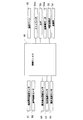
- FIG. 1 is a schematic refrigerant circuit diagram of an air conditioner according to an embodiment of the present invention.
- FIG. 1 is a schematic refrigerant circuit diagram of an air conditioner 100 according to an embodiment of the present invention.
- the air conditioner 100 is an air conditioner that can be operated by switching between a cooling operation and a heating operation by performing a vapor compression refrigeration cycle.
- the air conditioner 100 mainly includes an indoor unit 20 and an outdoor unit 30.
- the indoor unit 20 and the outdoor unit 30 constitute a refrigerant circuit 80 by being connected by a refrigerant pipe as a communication pipe.
- the refrigerant circuit 80 includes a main refrigerant circuit 81 and a discharge-suction bypass circuit 50.
- the main refrigerant circuit 81 is configured by a compressor 31, which will be described later, an outdoor heat exchanger 33, a main valve 35, and the indoor heat exchanger 21 connected by a refrigerant pipe.
- the air conditioner 100 performs the heating operation and the cooling operation by circulating the refrigerant in the main refrigerant circuit 81.
- the air conditioning apparatus 100 when performing the heating operation, circulates the refrigerant in the order of the compressor 31, the indoor heat exchanger 21, the main valve 35, and the outdoor heat exchanger 33.
- the air conditioner 100 circulates the refrigerant in the order of the compressor 31, the outdoor heat exchanger 33, the main valve 35, and the indoor heat exchanger 21.
- the discharge-suction bypass circuit 50 is connected to the main refrigerant circuit 81 so as to bypass a suction pipe 37 and a discharge pipe 38 of the compressor 31 described later.
- the air conditioner 100 then circulates the refrigerant in the main refrigerant circuit 81 and the discharge-suction bypass circuit 50 to remove frost attached to the outdoor heat exchanger 33 while heating the room that is the target of air conditioning. Perform a positive cycle defrosting operation.
- the discharge-suction bypass circuit 50 is normally not used during cooling operation or heating operation but is used when defrosting operation is performed.
- an HFC (hydrofluorocarbon) refrigerant such as R32 or R410A is enclosed as a refrigerant.
- the type of the refrigerant is not limited to the HFC refrigerant.
- the indoor unit 20 is installed indoors.
- the indoor unit 20 includes an indoor heat exchanger 21, an indoor fan 22, and various temperature sensors.
- the indoor heat exchanger 21 is a cross fin type fin-and-tube heat exchanger composed of heat transfer tubes and a large number of heat transfer fins.
- the indoor heat exchanger 21 functions as an evaporator that evaporates the refrigerant during the cooling operation, and functions as a condenser that condenses the high-pressure refrigerant during the heating operation.
- the indoor fan 22 sucks indoor air into the indoor unit 20, causes the air sucked in the indoor heat exchanger 21 and the refrigerant to exchange heat, and supplies the air after heat exchange with the refrigerant to the room. That is, the indoor fan 22 is a fan that supplies indoor air to the indoor heat exchanger 21 as a heating source or cooling source for the refrigerant flowing through the indoor heat exchanger 21.
- a centrifugal fan, a multiblade fan, etc. are used, for example.
- the various temperature sensors include an indoor heat exchange temperature sensor 61 and an indoor temperature sensor 62 (see FIG. 3).
- the indoor heat exchanger temperature sensor 61 is a thermistor that detects the temperature of the refrigerant flowing through the indoor heat exchanger 21.
- the indoor heat exchanger temperature sensor 61 is attached to the indoor heat exchanger 21.
- the room temperature sensor 62 is a thermistor for detecting the room temperature.
- the outdoor unit 30 is installed outdoors.
- the outdoor unit 30 mainly includes a compressor 31, a four-way switching valve 32, an outdoor heat exchanger 33, an outdoor fan 34, a main valve 35, a discharge-suction bypass circuit 50, and various temperature sensors. .
- the compressor 31 is a device that compresses the low-pressure refrigerant in the refrigeration cycle until it reaches a high pressure.
- the compressor 31 sucks the low-pressure refrigerant from the suction pipe 37, compresses the refrigerant, and discharges the high-pressure refrigerant.
- the compressor 31 has a sealed structure in which a rotary type or scroll type positive displacement compression element (not shown) is rotationally driven by a compressor motor 31m controlled by an inverter.
- a suction pipe 37 is connected to the compressor 31 on the suction side, and a discharge pipe 38 is connected to the discharge side.
- the suction pipe 37 is a refrigerant pipe that connects the suction part 31 b of the compressor 31 and the four-way switching valve 32.
- the suction pipe 37 is provided with a small-volume accumulator 36 attached to the compressor 31.
- the accumulator 36 is a gas-liquid separator that divides the incoming refrigerant into a gas phase and a liquid phase.
- the suction pipe 37 includes a trap pipe 37a including a U-shaped trap portion 37aa as shown in FIG.
- the trap pipe 37 a is a refrigerant pipe that connects the four-way switching valve 32 and the accumulator 36.
- the trap pipe 37a of this embodiment is a part of a pipe that connects the four-way switching valve 32 and the suction portion 31b of the compressor 31. Further, the trap tube 37a of the present embodiment is provided with two trap portions 37aa.
- the discharge pipe 38 is a refrigerant pipe that connects the discharge part 31 a of the compressor 31 and the four-way switching valve 32. Further, the suction pipe 37 and the discharge pipe 38 are connected by a bypass pipe 51 constituting a discharge-suction bypass circuit 50.
- the four-way switching valve 32 is a switching valve for switching the flow direction of the refrigerant in the main refrigerant circuit 81.
- the four-way switching valve 32 is connected to the discharge side of the compressor 31 and the indoor heat exchanger 21, and is connected to the outdoor heat exchanger 33 and the suction side of the compressor 31 (see the solid line in FIG. 1). ) And the discharge side of the compressor 31 and the outdoor heat exchanger 33, and the second state (see the broken line in FIG. 1) in which the indoor heat exchanger 21 and the suction side of the compressor 31 are connected.
- the circulation direction of the refrigerant in the main refrigerant circuit 81 is configured to be reversible.
- the four-way switching valve 32 is in the first state, and the refrigerant discharged from the compressor 31 is condensed in the indoor heat exchanger 21 to become liquid refrigerant, and after being decompressed in the main valve 35, The water is evaporated by the outdoor heat exchanger 33 and sucked into the compressor 31 through the accumulator 36.
- the four-way switching valve 32 is in the second state, and the refrigerant discharged from the compressor 31 is condensed by the outdoor heat exchanger 33 to become liquid refrigerant, and after being decompressed by the main valve 35, It evaporates in the indoor heat exchanger 21 and is sucked into the compressor 31 through the accumulator 36.
- the outdoor heat exchanger 33 is a cross-fin type fin-and-tube heat exchanger composed of heat transfer tubes and a large number of heat transfer fins.
- the outdoor heat exchanger 33 is a heat exchanger that functions as a refrigerant condenser that uses outside air as a cooling source during cooling operation, and that functions as a refrigerant evaporator that uses outside air as a heating source during heating operation.
- the main valve 35 is a motor valve with variable opening, and the main valve 35 in this embodiment is an electric expansion valve.
- the opening degree of the main valve 35 is adjusted and controlled by the control unit 40, and the pressure and flow rate of the refrigerant flowing through the main refrigerant circuit 81 are adjusted.
- the main valve 35 expands the refrigerant flowing from the outdoor heat exchanger 33 that functions as a condenser to the indoor heat exchanger 21 that functions as an evaporator.
- the main valve 35 expands the refrigerant flowing from the indoor heat exchanger 21 functioning as a condenser to the outdoor heat exchanger 33 functioning as an evaporator.
- the discharge-suction bypass circuit 50 is a circuit used during the normal cycle frost operation, and is connected to the main refrigerant circuit 81. In the forward cycle defrosting operation, the refrigerant flows in the main refrigerant circuit 81 in the same direction as in the heating operation.
- the discharge-suction bypass circuit 50 includes a bypass pipe 51 and an overheat valve 52.
- the bypass pipe 51 connects the suction pipe 37 and the discharge pipe 38 of the compressor 31.
- one end of the bypass pipe 51 is connected to the discharge pipe 38 of the main refrigerant circuit 81.
- the discharge pipe 38 is connected to the vicinity of the discharge portion 31 a of the compressor 31.
- the other end of the bypass pipe 51 is connected between the four-way switching valve 32 and the accumulator 36 in the suction pipe 37 of the main refrigerant circuit 81.
- the other end of the bypass pipe 51 is connected to the suction pipe 37 immediately after exiting the four-way switching valve 32 in the refrigerant flow direction during the normal cycle defrosting operation.
- the other end of the bypass pipe 51 is connected to the four-way switching valve 32 side with respect to the trap part 37aa of the trap pipe 37a.
- the overheat valve 52 is, for example, an electric valve with a variable opening.
- the opening degree of the superheat valve 52 is adjusted and controlled by the control unit 40 to adjust the flow rate of the refrigerant flowing through the bypass pipe 51.
- the overheat valve 52 is closed during the cooling operation or the heating operation, and the refrigerant does not flow through the bypass pipe 51.
- the overheat valve 52 is opened only during the normal cycle defrosting operation, and bypasses the refrigerant from the discharge side of the compressor 31 to the suction side of the compressor 31.
- the outdoor fan 34 sucks outdoor air into the outdoor unit 30 and exchanges heat between the air sucked in the outdoor heat exchanger 33 and the refrigerant, and the heat-exchanged air is transferred to the outside. Discharge. That is, the outdoor fan 34 is a fan that supplies outdoor air to the outdoor heat exchanger 33 as a cooling source or a heating source of the refrigerant flowing through the outdoor heat exchanger 33. For example, a propeller fan is used as the outdoor fan 34. The outdoor fan 34 is driven by a fan motor 34m capable of controlling the rotational speed.
- the outdoor unit 30 has various temperature sensors.
- the various temperature sensors include an outdoor heat exchange temperature sensor 63, a discharge temperature sensor 64, and an outdoor temperature sensor 65.
- the outdoor heat exchange temperature sensor 63 is a thermistor that detects the temperature of the refrigerant flowing through the outdoor heat exchanger 33.
- the outdoor heat exchange temperature sensor 63 is attached to the outdoor heat exchanger 33.
- the discharge temperature sensor 64 is a thermistor that detects the temperature of the refrigerant discharged from the compressor 31.
- the discharge temperature sensor 64 is provided outside the compressor 31, more specifically, in the discharge pipe 38 near the discharge portion 31 a of the compressor 31.
- the outdoor temperature sensor 65 is a thermistor that detects the outside air temperature.
- FIG. 3 is a control block diagram of the control unit 40 provided in the air conditioning apparatus 100. As shown in FIG. 3, the control unit 40 is connected to various devices included in the air conditioner 100, and operates various devices to perform various operations including a cooling operation, a heating operation, a normal cycle defrosting operation, and the like. Take control.
- control unit 40 is connected to an indoor heat exchange temperature sensor 61, an indoor temperature sensor 62, an outdoor heat exchange temperature sensor 63, a discharge temperature sensor 64, an outdoor temperature sensor 65, and the like. Based on the detection result by each sensor, the compressor motor 31m, the four-way switching valve 32, the fan motor 34m of the outdoor fan 34, the main valve 35, the overheat valve 52, the indoor fan 22 and the like are controlled.
- the control unit 40 determines that frost formation has occurred in the outdoor heat exchanger 33 during the heating operation, the control unit 40 switches the operation of the air conditioner 100 from the heating operation to the normal cycle defrosting operation, and the outdoor heat exchanger
- the operation of the air conditioner 100 is switched from the normal cycle defrosting operation to the heating operation.
- the control unit 40 switches the operation of the air conditioner 100 from the heating operation to the normal cycle defrosting operation based on the temperature of the refrigerant flowing through the outdoor heat exchanger 33 detected by the outdoor heat exchanger temperature sensor 63. And whether or not to switch from the normal cycle defrosting operation to the heating operation is determined.
- control unit 40 performs outdoor heat exchange when the temperature of the refrigerant flowing through the outdoor heat exchanger 33 detected by the outdoor heat exchanger temperature sensor 63 during the heating operation becomes equal to or lower than the defrosting operation start temperature. It is judged that frosting has occurred in the vessel 33, and the operation of the air conditioner 100 is switched from the heating operation to the normal cycle defrosting operation.
- the control unit 40 also performs outdoor heat exchange when the temperature of the refrigerant flowing through the outdoor heat exchanger 33 detected by the outdoor heat exchanger temperature sensor 63 during the positive cycle defrosting operation is equal to or higher than the defrosting operation end temperature. It is determined that the removal of frost in the vessel 33 has been completed, and the operation of the air conditioner 100 is switched from the normal cycle defrosting operation to the heating operation.
- FIG. 3 Operation
- movement of the air conditioning apparatus 100 is demonstrated using FIG.
- the operation of the air conditioning apparatus 100 is executed by the control unit 40.
- the air conditioner 100 can perform operations of cooling operation, heating operation, and forward cycle defrosting operation.
- the four-way switching valve 32 is switched to the first state (the state shown by the solid line in FIG. 1). Further, during the heating operation, the control unit 40 controls the operations of the compressor 31, the indoor fan 22, and the outdoor fan 34 so that the indoor temperature becomes the target temperature (set temperature), and is detected by the discharge temperature sensor 64. The opening degree of the main valve 35 is adjusted based on the refrigerant temperature on the discharge side of the compressor 31 to be performed. During the heating operation, the overheat valve 52 is fully closed.
- the low-pressure gas refrigerant in the refrigeration cycle is sucked into the compressor 31 and is compressed until it reaches a high pressure in the refrigeration cycle, and then discharged.
- the high-pressure gas refrigerant discharged from the compressor 31 is sent to the indoor heat exchanger 21 through the discharge pipe 38 and the four-way switching valve 32.
- the high-pressure gas refrigerant sent to the indoor heat exchanger 21 radiates heat by exchanging heat with indoor air supplied as a cooling source by the indoor fan 22 in the indoor heat exchanger 21 to become a high-pressure liquid refrigerant. . Thereby, indoor air is heated and indoor heating is performed by being supplied indoors.
- the high-pressure liquid refrigerant radiated by the indoor heat exchanger 21 is sent to the main valve 35.
- the high-pressure liquid refrigerant sent to the main valve 35 is depressurized to a low pressure in the refrigeration cycle.
- the refrigerant decompressed by the main valve 35 is sent to the outdoor heat exchanger 33.
- the low-pressure liquid refrigerant sent to the outdoor heat exchanger 33 exchanges heat with the outside air supplied as a heating source by the outdoor fan 34 in the outdoor heat exchanger 33 and evaporates to become a low-pressure gas refrigerant.
- the low-pressure refrigerant evaporated in the outdoor heat exchanger 33 flows through the trap pipe 37a through the four-way switching valve 32, and is again sucked into the compressor 31 through the accumulator 36.
- (3-2) Cooling Operation During the cooling operation, the four-way switching valve 32 is switched to the second state (the state indicated by the broken line in FIG. 1). Further, during the cooling operation, the control unit 40 controls the operations of the compressor 31, the indoor fan 22, and the outdoor fan 34 so that the temperature of the room (air-conditioning target space) becomes the target temperature (set temperature), and discharge The opening degree of the main valve 35 is adjusted based on the refrigerant temperature on the discharge side of the compressor 31 detected by the temperature sensor 64. During the cooling operation, the overheat valve 52 is fully closed.
- the low-pressure gas refrigerant in the refrigeration cycle is sucked into the compressor 31 and is compressed until it reaches a high pressure in the refrigeration cycle, and then discharged.
- the high-pressure gas refrigerant discharged from the compressor 31 is sent to the outdoor heat exchanger 33 through the discharge pipe 38 and the four-way switching valve 32.
- the high-pressure gas refrigerant sent to the outdoor heat exchanger 33 exchanges heat with the outside air supplied as a cooling source by the outdoor fan 34 in the outdoor heat exchanger 33, dissipates heat, and becomes high-pressure liquid refrigerant.
- the high-pressure liquid refrigerant that has radiated heat in the outdoor heat exchanger 33 is sent to the main valve 35.
- the high-pressure liquid refrigerant sent to the main valve 35 is depressurized by the main valve 35 to a low pressure in the refrigeration cycle.
- the low-pressure liquid refrigerant decompressed by the main valve 35 is sent to the indoor heat exchanger 21.
- the low-pressure refrigerant sent to the indoor heat exchanger 21 exchanges heat with indoor air supplied as a heating source by the indoor fan 22 in the indoor heat exchanger 21 and evaporates. As a result, the room air is cooled and then supplied to the room to cool the room.
- the low-pressure gas refrigerant evaporated in the indoor heat exchanger 21 flows through the trap pipe 37a through the four-way switching valve 32, and is again sucked into the compressor 31 through the accumulator 36.
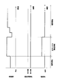
- FIG. 4 is a time chart showing an example of operations of the compressor 31, the four-way switching valve 32, and the overheating valve 52 when the forward cycle defrosting operation is performed.
- the positive cycle defrosting operation is an operation performed when it is determined that frost formation has occurred in the outdoor heat exchanger 33 during the heating operation as described above.
- the air conditioner 100 is operated while the four-way switching valve 32 is in the first state (the state indicated by the solid line in FIG. 1).
- the refrigerant flows in the main refrigerant circuit 81 in the same manner as in the heating operation. Therefore, it is possible to perform the defrosting while continuing the heating.
- the compressor motor 31m is operated at a predetermined rotational speed, preferably the maximum rotational speed. In this way, by operating the compressor motor 31m of the compressor 31 at the highest possible rotational speed, it is easy to keep the input power to the compressor 31 large and to secure the amount of heat for defrosting. Further, during the forward cycle defrosting operation, the indoor fan 22 is continuously operated to continue the heating operation. On the other hand, during the forward cycle defrosting operation, the driving of the outdoor fan 34 is stopped.
- the main valve 35 in the normal cycle defrosting operation, is controlled so that the temperature of the refrigerant flowing through the indoor heat exchanger 21 detected by the indoor heat exchanger temperature sensor 61 becomes the target temperature value. .
- the overheat valve 52 is opened so that the high-temperature and high-pressure gas refrigerant discharged from the compressor 31 is supplied to the suction pipe 37.
- the superheat valve 52 is controlled such that the degree of superheat of the discharged refrigerant detected by the discharge temperature sensor 64 becomes the target discharge superheat degree (for example, 10 deg).
- the low-pressure gas refrigerant in the refrigeration cycle is sucked into the compressor 31 and is compressed until it reaches a high pressure in the refrigeration cycle, and then discharged.
- a part of the high-pressure gas refrigerant discharged from the compressor 31 flows through the discharge pipe 38 to the four-way switching valve 32, and the rest flows from the middle of the discharge pipe 38 to the bypass pipe 51.
- the high-pressure gas refrigerant that has reached the four-way switching valve 32 is sent to the indoor heat exchanger 21.
- the high-pressure gas refrigerant sent to the indoor heat exchanger 21 radiates heat by exchanging heat with indoor air supplied as a cooling source by the indoor fan 22 in the indoor heat exchanger 21 to become a high-pressure liquid refrigerant. . Thereby, indoor air is heated and indoor heating is performed by being supplied indoors.
- the high-pressure liquid refrigerant radiated by the indoor heat exchanger 21 is sent to the main valve 35.
- the high-pressure liquid refrigerant sent to the main valve 35 is depressurized to a low pressure corresponding to the opening of the main valve 35 and sent to the outdoor heat exchanger 33.
- the liquid refrigerant sent to the outdoor heat exchanger 33 melts frost adhering to the outdoor heat exchanger 33 by flowing through the outdoor heat exchanger 33, and then sent to the four-way switching valve 32.
- the refrigerant that has reached the four-way switching valve 32 reaches a merging portion 90 that is a connection portion between the suction pipe 37 and the bypass pipe 51.
- the high-pressure gas refrigerant that has flowed from the discharge pipe 38 to the bypass pipe 51 reaches the junction 90 through the overheat valve 52.
- the high-pressure gas refrigerant discharged from the compressor 31 and the low-pressure refrigerant flowing from the outdoor heat exchanger 33 through the four-way switching valve 32 merge at the junction 90.
- the high-pressure gas refrigerant and the low-pressure refrigerant merged in the merge section 90 flow through the trap pipe 37a and the accumulator 36 while being mixed, and are sucked into the compressor 31 again.
- the refrigerant that has been cooled by performing defrosting in the outdoor heat exchanger 33 and the high-temperature refrigerant that is supplied through the superheater valve 52 because the superheater valve 52 is opened. Are merged and mixed in the merging section 90, so that liquid back of the compressor 31 is prevented and the compressor 31 can be operated continuously.
- the junction 90 between the refrigerant that has circulated through the main refrigerant circuit 81 and the refrigerant that has been bypassed through the discharge-suction bypass circuit 50 is provided between the four-way switching valve 32 and the compressor 31. It arrange
- the other end of the bypass pipe 51 is connected to the suction pipe 37 immediately after exiting the four-way switching valve 32 in the refrigerant flow direction during the normal cycle defrosting operation. That is, the merging unit 90 is disposed immediately after exiting the four-way switching valve 32 in the refrigerant flow direction during the forward cycle defrosting operation. For this reason, the distance from the confluence
- the suction pipe 37 includes a trap pipe 37a, and the four-way switching valve 32 and the accumulator 36 are connected by the trap pipe 37a.
- the main refrigerant circuit 81 includes the trap pipe 37a as a pipe connecting the four-way switching valve 32 and the suction portion 31b of the compressor 31.
- the four-way switching valve 32 and the accumulator 36 are connected by the trap pipe 37a, the four-way switching valve is compared with the case where the four-way switching valve 32 and the accumulator 36 are connected by a refrigerant pipe that is not curved. A distance from 32 to the suction portion 31b of the compressor 31 can be secured.
- merging part 90 is arrange
- the merging portion 90 is disposed upstream of the trap portion 37aa of the trap pipe 37a, so that the refrigerant circulating in the main refrigerant circuit 81 and the refrigerant bypassed through the discharge-suction bypass circuit 50 are mixed. Can be promoted.
- the air conditioner 100 performs a defrosting operation in which the refrigerant circulates in the main refrigerant circuit 81 in the same direction as in the cooling operation, that is, the compressor 31, the outdoor heat exchanger 33, A reverse cycle defrosting operation in which the refrigerant circulates in the order of the main valve 35 and the indoor heat exchanger 21 may be performed.
- the reverse cycle defrosting operation since the high-temperature gas refrigerant discharged from the compressor 31 flows through the outdoor heat exchanger 33, the time required for defrosting the outdoor heat exchanger 33 can be shortened.
- the discharge-suction bypass circuit 50 is not used during the reverse cycle defrosting operation, and the discharge-suction bypass circuit 50 is used in the pressure equalization operation performed before and after the reverse cycle defrosting operation. That is, the superheat valve 52 of the discharge-suction bypass circuit 50 is closed during the reverse cycle defrosting operation, and the superheat valve 52 of the discharge-suction bypass circuit 50 is opened only during the pressure equalization operation.
- the reverse cycle defrosting operation and the pressure equalizing operation will be described.
- the operations of the pressure equalizing operation and the reverse cycle defrosting operation of the air conditioner 100 are executed by the control unit 40. Note that the selection of whether to perform the normal cycle defrosting operation or the reverse cycle defrosting operation as the defrosting operation may be determined by user settings, and is determined by the control unit 40 based on conditions such as the outside air temperature. Also good.
- the control unit 40 When the reverse cycle defrosting operation is selected as the defrosting operation, the control unit 40 performs the pressure equalizing operation from the heating operation when determining that frost formation has occurred in the outdoor heat exchanger 33 during the heating operation. After that, when the operation of the air conditioner 100 is switched to the reverse cycle defrosting operation and it is determined that the frost removal in the outdoor heat exchanger 33 is completed, the air is switched from the reverse cycle defrosting operation to the heating operation through the pressure equalization operation. The operation of the harmony device 100 is switched.
- the pressure equalizing operation is an operation that is performed before the operation of the air conditioning apparatus 100 is switched from the heating operation to the reverse cycle defrosting operation and before the reverse cycle defrosting operation is switched to the heating operation. This operation is performed in order to avoid a state in which the difference in refrigerant pressure between the suction side and the suction side of the compressor 31 is excessive. That is, the pressure equalizing operation is an operation performed before the state of the four-way switching valve 32 is switched when the reverse cycle defrosting operation is performed.
- the pressure equalizing operation is an operation performed when the control unit 40 executes pressure adjustment control. In the pressure adjustment control, the rotation of the compressor motor 31m is stopped and the driving of the compressor is stopped. In the pressure adjustment control, the driving of the indoor fan 22 and the outdoor fan 34 is also stopped.
- the overheat valve 52 is opened so as to have a predetermined opening. At this time, the opening of the main valve 35 and the state of the four-way switching valve 32 are maintained in the state before the pressure equalizing operation is performed (heating operation or reverse cycle defrosting operation). In the pressure equalizing operation, the superheat valve 52 is opened, so that the difference in refrigerant pressure between the discharge side of the compressor 31 and the suction side of the compressor 31 is alleviated.
- the reverse cycle defrosting operation is an operation performed when it is determined that frost formation has occurred in the outdoor heat exchanger 33 during the heating operation as described above.
- the four-way switching valve 32 is switched to the second state (the state indicated by the broken line in FIG. 1), similarly to the cooling operation.
- the compressor motor 31m is operated at a predetermined rotational speed. Further, during the reverse cycle defrosting operation, the driving of the indoor fan 22 and the outdoor fan 34 is stopped. Further, during the reverse cycle defrosting operation, the main valve 35 is controlled to have a predetermined opening, and the overheat valve 52 is closed. Since the overheat valve 52 is closed during the reverse cycle defrosting operation, the refrigerant flow through the discharge-suction bypass circuit 50 is blocked.
- the low-pressure gas refrigerant in the refrigeration cycle is sucked into the compressor 31 and compressed after being compressed to a high pressure in the refrigeration cycle, and then discharged.
- the high-pressure gas refrigerant discharged from the compressor 31 is sent to the outdoor heat exchanger 33 through the discharge pipe 38 and the four-way switching valve 32.
- the high-pressure gas refrigerant sent to the outdoor heat exchanger 33 melts frost adhering to the outdoor heat exchanger 33 by flowing through the outdoor heat exchanger 33, and then sent to the main valve 35.
- the high-pressure refrigerant sent to the main valve 35 is depressurized by the main valve 35, flows through the trap pipe 37 a through the indoor heat exchanger 21 and the four-way switching valve 32, and again enters the compressor 31 through the accumulator 36. Inhaled.
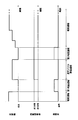
- FIG. 5 is a time chart illustrating an example of operations of the compressor 31, the four-way switching valve 32, and the overheat valve 52 when the reverse cycle defrosting operation is performed.
- the pressure equalization operation performed before switching from the heating operation to the reverse cycle defrosting operation is referred to as the first pressure equalization operation, and the pressure equalization performed before switching from the reverse cycle defrosting operation to the heating operation.
- the pressure operation is called second pressure equalization operation.
- the control unit 40 determines that frost formation has occurred in the outdoor heat exchanger 33 during the heating operation, the control unit 40 switches the operation of the air conditioner 100 from the heating operation to the first pressure equalizing operation. Specifically, the control unit 40 stops the drive of the compressor 31, the indoor fan 22, and the outdoor fan 34, and performs control so that the overheat valve 52 is opened to a predetermined opening degree. In the first pressure equalization operation, the overheat valve 52 may be opened simultaneously with the stop of the compressor 31, or the overheat valve 52 may be opened after the drive of the compressor 31 is stopped.
- the control unit 40 switches the operation of the air conditioner 100 from the first pressure equalizing operation to the reverse cycle defrosting operation. Specifically, the control unit 40 switches the state of the four-way switching valve 32 from the first state to the second state, starts driving the compressor 31, and fully closes the overheat valve 52.
- the state of the four-way switching valve 32 may be switched from the first state to the second state at the same time as the overheating valve 52 is closed. After the heat valve 52 is closed, the state of the four-way switching valve 32 may be switched from the first state to the second state. Thereby, in the air conditioning apparatus 100, a reverse cycle defrosting operation is performed.
- the control unit 40 determines that the frost removal in the outdoor heat exchanger 33 has been completed during the reverse cycle defrosting operation, the operation of the air conditioner 100 is changed from the reverse cycle defrosting operation to the second pressure equalization operation.
- Switch. Specifically, the control unit 40 stops the drive of the compressor 31 and controls the overheat valve 52 to open to a predetermined opening degree.
- the superheat valve 52 may be opened simultaneously with the stop of the compressor 31 drive, or the overheat valve 52 may be opened after the drive of the compressor 31 is stopped.
- the control unit 40 switches the operation of the air conditioner 100 from the second pressure equalization operation to the heating operation. Specifically, the control unit 40 switches the state of the four-way switching valve 32 from the second state to the first state, starts driving the compressor 31, the indoor fan 22, and the outdoor fan 34, and all the overheat valves 52 are turned on. Close. Note that when the operation is switched from the second pressure equalization operation to the heating operation, the state of the four-way switching valve 32 may be switched from the second state to the first state at the same time as the overheat valve 52 is closed. After being closed, the state of the four-way switching valve 32 may be switched from the second state to the first state. Thereby, in the air conditioning apparatus 100, heating operation is restarted.
- the main refrigerant circuit 81 can perform the reverse cycle defrosting operation in addition to the normal cycle defrosting operation.
- the state of the four-way switching valve 32 during the reverse cycle defrosting operation is the same second state as during the cooling operation.
- the state of the four-way switching valve 32 during the normal cycle defrosting operation is the same first state as during the heating operation. That is, it can be said that the reverse cycle defrosting operation is an operation performed in a state where the state of the four-way switching valve 32 is switched from the state of the normal cycle defrosting operation.
- the normal cycle defrosting operation and the reverse cycle defrosting operation are operations performed while the heating operation is performed.
- the operation of the air conditioner 100 is switched from the heating operation to the normal cycle defrosting operation, and When switching from cycle defrosting operation to heating operation, there is no need to switch the state of the four-way switching valve 32.
- the drive of the compressor 31 is temporarily stopped and a predetermined time (hereinafter referred to as pressure equalizing time) has elapsed. Then, means for switching the state of the four-way switching valve 32 can be considered. However, with this means, heating operation and defrosting operation are not performed until the pressure equalization time elapses after the drive of the compressor 31 is stopped. May cause discomfort.
- the pressure equalizing operation is performed before and after the reverse cycle defrosting operation, that is, when the state of the four-way switching valve 32 is switched.
- the overheating valve 52 is opened, so that relaxation of the refrigerant pressure difference between the discharge side of the compressor 31 and the suction side of the compressor 31 can be promoted.
- the pressure equalizing operation since the pressure equalizing operation is performed, it is possible to avoid a state where the difference in refrigerant pressure between the discharge side of the compressor 31 and the suction side of the compressor 31 is excessive. The generation of noise that occurs when the four-way switching valve 32 is switched can be suppressed, and the pressure equalization time can be shortened.
- the discharge-suction bypass circuit 50 when the forward cycle defrosting operation is performed, the discharge-suction bypass circuit 50 is used as a circuit for preventing liquid back to the compressor 31, and the reverse cycle defrosting operation is performed. Is performed, the discharge-suction bypass circuit 50 can be used as a circuit for promoting the relaxation of the refrigerant pressure difference between the discharge side of the compressor 31 and the suction side of the compressor 31.
- the present invention can suppress an increase in the amount of refrigerant retained and suppress a decrease in refrigerant controllability, and is effectively applied to an air conditioner that performs a defrosting operation.
Landscapes
- Engineering & Computer Science (AREA)
- Physics & Mathematics (AREA)
- Mechanical Engineering (AREA)
- Thermal Sciences (AREA)
- General Engineering & Computer Science (AREA)
- Air Conditioning Control Device (AREA)
Abstract
空気調和装置(100)は、圧縮機(31)、四路切替弁(32)、室内熱交換器(21)、主弁(35)及び室外熱交換器(33)を有し正サイクル除霜運転を行うことが可能な主冷媒回路(81)と、過熱弁(52)を有する吐出-吸入バイパス回路(50)とを備える。吐出-吸入バイパス回路(50)は、正サイクル除霜運転時に、過熱弁(52)を開けることで、圧縮機(31)の吐出側から圧縮機(31)の吸入側に冷媒をバイパスすることが可能になるように主冷媒回路(81)に接続されている。正サイクル除霜運転時に吐出-吸入バイパス回路(50)を通じてバイパスされた冷媒と、主冷媒回路(81)を流れてきた冷媒との合流部(90)は、四路切替弁(32)と圧縮機(31)の吸入部(31b)との間に配置されている。
Description
本発明は、空気調和装置に関する。
従来より、暖房運転時に室外熱交換器に生じた着霜を除去する除霜運転を行う空気調和装置がある。この除霜運転としては、例えば、特許文献1(特開昭61-262560号公報)に開示されているように、暖房を継続しながら除霜を行うことが可能な正サイクル除霜運転が知られている。
特許文献1に開示されている空気調和装置は、圧縮機と、四路切替弁と、室内熱交換器と、電動膨張弁と、室外熱交換器とを接続する冷媒回路に、圧縮機の吐出側と室外熱交換器の暖房運転時の出口側とをバイパスするバイパス回路が接続されている。そして、正サイクル除霜運転時には、このバイパス回路に吐出ガスの一部を流すことで、室外熱交換器を流れて圧縮機に吸入される冷媒の乾き度を上昇させ、圧縮機への液バックを軽減している。
ところで、特許文献1に開示されているバイパス回路(以下、吐出-吸入バイパス回路という)は、圧縮機の吐出側と四路切替弁との間と、室外熱交換器と四路切替弁との間と、をバイパスする構成であるため、吐出-吸入バイパス回路の長さが長くなっている。このように吐出-吸入バイパス回路の長さが長いと、保有冷媒量が増加するとともに、冷媒制御の応答性が遅くなるため冷媒制御性が低下してしまうという問題がある。
そこで、本発明の課題は、保有冷媒量の増加を抑制し、かつ冷媒制御性の低下を抑制することができる空気調和装置を提供することにある。
本発明の第1観点に係る空気調和装置は、主冷媒回路と、吐出-吸入バイパス回路と、を備える。主冷媒回路は、圧縮機と、四路切替弁と、室内熱交換器と、主弁と、室外熱交換器と、を有する。主冷媒回路は、圧縮機、四路切替弁、室内熱交換器、主弁、室外熱交換器、四路切替弁の順に冷媒を循環させつつ、室外熱交換器を除霜する正サイクル除霜運転を行うことが可能である。吐出-吸入バイパス回路は、過熱弁を有する。吐出-吸入バイパス回路は、正サイクル除霜運転時に、過熱弁を開けることで、圧縮機の吐出側から圧縮機の吸入側に冷媒をバイパスすることが可能になるように主冷媒回路に接続されている。そして、この空気調和装置では、正サイクル除霜運転時に吐出-吸入バイパス回路を通じてバイパスされた冷媒と、主冷媒回路を流れてきた冷媒との合流部は、四路切替弁と圧縮機の吸入部との間に配置されている。
本発明の第1観点に係る空気調和装置では、正サイクル除霜運転時に吐出-吸入バイパス回路を通じてバイパスされた冷媒と主冷媒回路を流れてきた冷媒との合流部が、四路切替弁と圧縮機の吸入部との間に配置されている。このため、合流部が室外熱交換器と四路切替弁との間に配置されている場合と比較して、吐出-吸入バイパス回路の長さを短くすることができる。
これにより、保有冷媒量の増加を抑制し、かつ冷媒制御性の低下を抑制することができる。
本発明の第2観点に係る空気調和装置は、第1観点の空気調和装置において、合流部は、正サイクル除霜運転時の冷媒の流れ方向において、四路切替弁を出た直後に配置されている。このため、合流部から圧縮機の吸入部までの距離を確保することができ、この結果、主冷媒回路を流れてきた冷媒と吐出-吸入バイパス回路を通じてバイパスされた冷媒との混合を促進することができる。さらに、合流部から圧縮機の吸入部までの距離を確保することができるため、圧縮機の振動によって吐出-吸入バイパス回路に生じる応力影響を低減することができる。
本発明の第3観点に係る空気調和装置は、第1観点又は第2観点の空気調和装置において、主冷媒回路は、四路切替弁と圧縮機の吸入部とを接続する配管として、U字状のトラップ管を含む。このため、前記配管としてトラップ管が含まれない場合と比較して四路切替弁から圧縮機の吸入部までの距離を確保することができるため、合流部がトラップ管よりも上流側に配置されていれば、主冷媒回路を流れてきた冷媒と吐出-吸入バイパス回路を通じてバイパスされた冷媒との混合を促進することができる。
本発明の第4観点に係る空気調和装置は、第1観点から第3観点のいずれかの空気調和装置において、主冷媒回路は、逆サイクル除霜運転を行うことが可能である。逆サイクル除霜運転は、四路切替弁の状態を正サイクル除霜運転の状態から切り替えることで、圧縮機、四路切替弁、室外熱交換器、主弁、室内熱交換器、四路切替弁の順に冷媒を循環させつつ、室外熱交換器を除霜する運転である。逆サイクル除霜運転時には、過熱弁を閉じて吐出-吸入バイパス回路を通じた冷媒の流通が遮断される。この空気調和装置では、正サイクル除霜運転だけでなく、逆サイクル除霜運転を行うことができる。
本発明の第5観点に係る空気調和装置は、第4観点の空気調和装置において、逆サイクル除霜運転が行われる場合には、四路切替弁を切り替える前に、圧力調整制御を行う。圧力調整制御では、圧縮機の吐出側と圧縮機の吸入側との冷媒圧力の差が過剰についている状態を回避するために、過熱弁が開けられる。この空気調和装置では、逆サイクル除霜運転時には四路切替弁を切り替える前に圧力調整制御が行われるため、四路切替弁を切り替える際の騒音の発生を低減することができる。
本発明の第1観点に係る空気調和装置では、保有冷媒量の増加を抑制し、かつ冷媒制御性の低下を抑制することができる。
本発明の第2観点に係る空気調和装置では、主冷媒回路を流れてきた冷媒と吐出-吸入バイパス回路を通じてバイパスされた冷媒との混合を促進することができ、かつ吐出-吸入バイパス回路に生じる応力影響を低減することができる。
本発明の第3観点に係る空気調和装置では、主冷媒回路を流れてきた冷媒と吐出-吸入バイパス回路を通じてバイパスされた冷媒との混合を促進することができる。
本発明の第4観点に係る空気調和装置では、正サイクル除霜運転だけでなく、逆サイクル除霜運転を行うことができる。
本発明の第5観点に係る空気調和装置では、四路切替弁を切り替える際の騒音の発生を低減することができる。
以下、本発明に係る空気調和装置の一実施形態について、図面を用いて説明する。なお、本発明に係る空気調和装置の具体的な構成は、下記の実施形態に限られるものではなく、発明の要旨を逸脱しない範囲で適宜変更可能である。
(1)全体構成
図1は、本発明の一実施形態に係る空気調和装置100の概略冷媒回路図である。空気調和装置100は、蒸気圧縮式の冷凍サイクルを行うことによって、冷房運転と暖房運転とを切り替えて運転可能な空気調和装置である。
図1は、本発明の一実施形態に係る空気調和装置100の概略冷媒回路図である。空気調和装置100は、蒸気圧縮式の冷凍サイクルを行うことによって、冷房運転と暖房運転とを切り替えて運転可能な空気調和装置である。
空気調和装置100は、図1に示すように、主に、室内ユニット20と、室外ユニット30と、を備える。
室内ユニット20と、室外ユニット30とは、連絡配管としての冷媒配管によって接続されて冷媒回路80を構成する。冷媒回路80は、主冷媒回路81と、吐出-吸入バイパス回路50と、を有する。主冷媒回路81は、後述する圧縮機31と、室外熱交換器33と、主弁35と、室内熱交換器21とが冷媒配管によって接続されて構成されている。そして、空気調和装置100は、主冷媒回路81内に冷媒を循環させて暖房運転及び冷房運転を行う。例えば、暖房運転を行う場合には、空気調和装置100は、圧縮機31、室内熱交換器21、主弁35、室外熱交換器33の順に冷媒を循環させる。また、冷房運転を行う場合には、空気調和装置100は、圧縮機31、室外熱交換器33、主弁35、室内熱交換器21の順に冷媒を循環させる。
また、吐出-吸入バイパス回路50は、後述する圧縮機31の吸入管37と吐出管38とをバイパスするように主冷媒回路81に接続されている。そして、空気調和装置100は、主冷媒回路81内及び吐出-吸入バイパス回路50内に冷媒を循環させて、空気調和の対象である室内を暖房しながら室外熱交換器33に付着した霜を除去する正サイクル除霜運転を行う。吐出-吸入バイパス回路50は、通常、冷房運転時や暖房運転時には使用されず、除霜運転が行われる際に使用される。
なお、この空気調和装置100には、冷媒として、例えばR32やR410A等のHFC(ハイドロフルオロカーボン)冷媒が封入されている。ただし、冷媒の種類は、HFC冷媒に限定されるものではない。
(2)詳細構成
(2-1)室内ユニット
室内ユニット20は、室内に設置される。室内ユニット20は、室内熱交換器21、室内ファン22、及び各種温度センサを有する。
(2-1)室内ユニット
室内ユニット20は、室内に設置される。室内ユニット20は、室内熱交換器21、室内ファン22、及び各種温度センサを有する。
室内熱交換器21は、伝熱管と多数の伝熱フィンとにより構成されたクロスフィン式のフィン・アンド・チューブ型熱交換器である。室内熱交換器21は、冷房運転時には冷媒を蒸発させる蒸発器として機能し、暖房運転時には高圧の冷媒を凝縮させる凝縮器として機能する。
室内ファン22は、室内ユニット20内に室内の空気を吸入し、室内熱交換器21において吸入した空気と冷媒とを熱交換させ、室内に冷媒との熱交換後の空気を供給する。すなわち、室内ファン22は、室内熱交換器21を流れる冷媒の加熱源又は冷却源としての室内空気を室内熱交換器21に供給するファンである。なお、室内ファン22としては、例えば遠心ファンや多翼ファン等が使用される。
各種温度センサには、室内熱交温度センサ61、及び室内温度センサ62(図3参照)が含まれる。室内熱交温度センサ61は、室内熱交換器21を流れる冷媒の温度を検出するサーミスタである。室内熱交温度センサ61は、室内熱交換器21に取り付けられている。室内温度センサ62は、室内温度を検出するためのサーミスタである。
(2-2)室外ユニット
室外ユニット30は、室外に設置されている。また、室外ユニット30は、主に、圧縮機31、四路切替弁32、室外熱交換器33、室外ファン34、主弁35、吐出-吸入バイパス回路50、及び各種温度センサを有している。
室外ユニット30は、室外に設置されている。また、室外ユニット30は、主に、圧縮機31、四路切替弁32、室外熱交換器33、室外ファン34、主弁35、吐出-吸入バイパス回路50、及び各種温度センサを有している。
(2-2-1)圧縮機
圧縮機31は、冷凍サイクルにおける低圧の冷媒を高圧になるまで圧縮する機器である。圧縮機31は、吸入管37から低圧の冷媒を吸入し、冷媒の圧縮を行って高圧の冷媒を吐出する。圧縮機31は、ロータリ式やスクロール式等の容積式の圧縮要素(図示せず)をインバータにより制御される圧縮機モータ31mによって回転駆動する密閉式構造となっている。圧縮機31には、吸入側に吸入管37が接続されており、吐出側に吐出管38が接続されている。
圧縮機31は、冷凍サイクルにおける低圧の冷媒を高圧になるまで圧縮する機器である。圧縮機31は、吸入管37から低圧の冷媒を吸入し、冷媒の圧縮を行って高圧の冷媒を吐出する。圧縮機31は、ロータリ式やスクロール式等の容積式の圧縮要素(図示せず)をインバータにより制御される圧縮機モータ31mによって回転駆動する密閉式構造となっている。圧縮機31には、吸入側に吸入管37が接続されており、吐出側に吐出管38が接続されている。
吸入管37は、圧縮機31の吸入部31bと四路切替弁32とを接続する冷媒配管である。また、吸入管37には、圧縮機31に付属する小容積のアキュムレータ36が設けられている。アキュムレータ36は、流入してくる冷媒を、気相と液相とに分ける気液分離器である。また、吸入管37は、図2に示すように、U字状のトラップ部37aaを含むトラップ管37aを含む。トラップ管37aは、四路切替弁32とアキュムレータ36とを接続する冷媒配管である。すなわち、本実施形態のトラップ管37aは、四路切替弁32と圧縮機31の吸入部31bとを接続する配管の一部であるといえる。また、本実施形態のトラップ管37aには、トラップ部37aaが2つ設けられている。
吐出管38は、圧縮機31の吐出部31aと四路切替弁32とを接続する冷媒配管である。また、吸入管37と吐出管38とは、吐出-吸入バイパス回路50を構成するバイパス管51により接続されている。
(2-2-2)四路切替弁
四路切替弁32は、主冷媒回路81における冷媒の流れる方向を切り替えるための切替弁である。四路切替弁32は、圧縮機31の吐出側と室内熱交換器21と接続し、かつ、室外熱交換器33と圧縮機31の吸入側とを接続する第1状態(図1の実線参照)と、圧縮機31の吐出側と室外熱交換器33とを接続し、かつ、室内熱交換器21と圧縮機31の吸入側とを接続する第2状態(図1の破線参照)とに切り替わることで、主冷媒回路81における冷媒の循環方向が可逆に構成されている。
四路切替弁32は、主冷媒回路81における冷媒の流れる方向を切り替えるための切替弁である。四路切替弁32は、圧縮機31の吐出側と室内熱交換器21と接続し、かつ、室外熱交換器33と圧縮機31の吸入側とを接続する第1状態(図1の実線参照)と、圧縮機31の吐出側と室外熱交換器33とを接続し、かつ、室内熱交換器21と圧縮機31の吸入側とを接続する第2状態(図1の破線参照)とに切り替わることで、主冷媒回路81における冷媒の循環方向が可逆に構成されている。
そして、暖房運転時には、四路切替弁32が第1状態となっており、圧縮機31から吐出した冷媒は室内熱交換器21で凝縮されて液冷媒となり、主弁35で減圧された後、室外熱交換器33で蒸発器し、アキュムレータ36を介して圧縮機31へと吸入される。一方、冷房運転時には、四路切替弁32が第2状態となっており、圧縮機31から吐出した冷媒は室外熱交換器33で凝縮されて液冷媒となり、主弁35で減圧された後、室内熱交換器21で蒸発し、アキュムレータ36を介して圧縮機31へと吸入される。
(2-2-3)室外熱交換器
室外熱交換器33は、伝熱管と多数の伝熱フィンとにより構成されたクロスフィン式のフィン・アンド・チューブ型熱交換器である。室外熱交換器33は、冷房運転時には外気を冷却源とする冷媒の凝縮器として機能し、暖房運転時には外気を加熱源とする冷媒の蒸発器として機能する熱交換器である。
室外熱交換器33は、伝熱管と多数の伝熱フィンとにより構成されたクロスフィン式のフィン・アンド・チューブ型熱交換器である。室外熱交換器33は、冷房運転時には外気を冷却源とする冷媒の凝縮器として機能し、暖房運転時には外気を加熱源とする冷媒の蒸発器として機能する熱交換器である。
(2-2-4)主弁
主弁35は開度可変の電動弁であって、本実施形態における主弁35は電動膨張弁である。主弁35は、制御ユニット40により開度が調整制御され、主冷媒回路81を流れる冷媒の圧力や流量の調節を行う。主弁35は、冷房運転時には、凝縮器として機能する室外熱交換器33から、蒸発器として機能する室内熱交換器21へと流れる冷媒を膨張させる。また、暖房運転時には、主弁35は、凝縮器として機能する室内熱交換器21から、蒸発器として機能する室外熱交換器33へと流れる冷媒を膨張させる。
主弁35は開度可変の電動弁であって、本実施形態における主弁35は電動膨張弁である。主弁35は、制御ユニット40により開度が調整制御され、主冷媒回路81を流れる冷媒の圧力や流量の調節を行う。主弁35は、冷房運転時には、凝縮器として機能する室外熱交換器33から、蒸発器として機能する室内熱交換器21へと流れる冷媒を膨張させる。また、暖房運転時には、主弁35は、凝縮器として機能する室内熱交換器21から、蒸発器として機能する室外熱交換器33へと流れる冷媒を膨張させる。
(2-2-5)吐出-吸入バイパス回路
吐出-吸入バイパス回路50は、上述したように、正サイクル霜運転時に用いられる回路であり、主冷媒回路81に接続されている。なお、正サイクル除霜運転では、主冷媒回路81内を暖房運転時と同じ方向に冷媒が流れる。
吐出-吸入バイパス回路50は、上述したように、正サイクル霜運転時に用いられる回路であり、主冷媒回路81に接続されている。なお、正サイクル除霜運転では、主冷媒回路81内を暖房運転時と同じ方向に冷媒が流れる。
吐出-吸入バイパス回路50は、バイパス管51と、過熱弁52とを有する。バイパス管51は、圧縮機31の吸入管37と吐出管38とを接続する。具体的には、バイパス管51の一端は、主冷媒回路81の吐出管38に接続されており、例えば吐出管38において圧縮機31の吐出部31a近傍に接続されている。また、バイパス管51の他端は、主冷媒回路81の吸入管37において四路切替弁32とアキュムレータ36との間に接続されている。なお、本実施形態では、バイパス管51の他端は、吸入管37において、正サイクル除霜運転時の冷媒の流れ方向で四路切替弁32を出た直後に接続されている。具体的には、バイパス管51の他端は、トラップ管37aのトラップ部37aaよりも四路切替弁32側に接続されている。
過熱弁52は、例えば開度可変の電動弁である。過熱弁52は、制御ユニット40により開度が調整制御され、バイパス管51を流れる冷媒の流量調節を行う。なお、過熱弁52は、冷房運転時や暖房運転時には閉じられており、バイパス管51には冷媒は流れない。過熱弁52は、正サイクル除霜運転時にのみ開かれ、圧縮機31の吐出側から圧縮機31の吸入側に冷媒をバイパスする。
(2-2-6)室外ファン
室外ファン34は、室外ユニット30内に室外の空気を吸入し、室外熱交換器33において吸入した空気と冷媒と熱交換させ、熱交換後の空気を外部に排出する。すなわち、室外ファン34は、室外熱交換器33を流れる冷媒の冷却源又は加熱源としての室外空気を室外熱交換器33に供給するファンである。室外ファン34としては、例えばプロペラファンが使用される。室外ファン34は、回転数制御が可能なファンモータ34mによって駆動される。
室外ファン34は、室外ユニット30内に室外の空気を吸入し、室外熱交換器33において吸入した空気と冷媒と熱交換させ、熱交換後の空気を外部に排出する。すなわち、室外ファン34は、室外熱交換器33を流れる冷媒の冷却源又は加熱源としての室外空気を室外熱交換器33に供給するファンである。室外ファン34としては、例えばプロペラファンが使用される。室外ファン34は、回転数制御が可能なファンモータ34mによって駆動される。
(2-2-7)各種温度センサ
室外ユニット30は、各種温度センサを有している。各種温度センサには、室外熱交温度センサ63、吐出温度センサ64、及び室外温度センサ65が含まれる。室外熱交温度センサ63は、室外熱交換器33を流れる冷媒の温度を検出するサーミスタである。室外熱交温度センサ63は、室外熱交換器33に取り付けられている。吐出温度センサ64は、圧縮機31から吐出される冷媒の温度を検出するサーミスタである。吐出温度センサ64は、圧縮機31の外部、より具体的には、圧縮機31の吐出部31a近傍の吐出管38に設けられる。室外温度センサ65は、外気温度を検出するサーミスタである。
室外ユニット30は、各種温度センサを有している。各種温度センサには、室外熱交温度センサ63、吐出温度センサ64、及び室外温度センサ65が含まれる。室外熱交温度センサ63は、室外熱交換器33を流れる冷媒の温度を検出するサーミスタである。室外熱交温度センサ63は、室外熱交換器33に取り付けられている。吐出温度センサ64は、圧縮機31から吐出される冷媒の温度を検出するサーミスタである。吐出温度センサ64は、圧縮機31の外部、より具体的には、圧縮機31の吐出部31a近傍の吐出管38に設けられる。室外温度センサ65は、外気温度を検出するサーミスタである。
(2-3)制御ユニット
図3は、空気調和装置100の備える制御ユニット40の制御ブロック図である。制御ユニット40は、図3に示すように、空気調和装置100の有する各種機器と接続されており、冷房運転、暖房運転、正サイクル除霜運転等を含む各種運転を行うために各種機器の動作制御を行う。
図3は、空気調和装置100の備える制御ユニット40の制御ブロック図である。制御ユニット40は、図3に示すように、空気調和装置100の有する各種機器と接続されており、冷房運転、暖房運転、正サイクル除霜運転等を含む各種運転を行うために各種機器の動作制御を行う。
また、制御ユニット40は、図3に示すように、室内熱交温度センサ61、室内温度センサ62、室外熱交温度センサ63、吐出温度センサ64、及び室外温度センサ65等と接続されており、各センサによる検出結果に基づいて圧縮機モータ31m、四路切替弁32、室外ファン34のファンモータ34m、主弁35、過熱弁52、及び室内ファン22等を制御する。
また、制御ユニット40は、暖房運転中に室外熱交換器33において着霜が発生したと判断し場合には暖房運転から正サイクル除霜運転に空気調和装置100の運転を切り替え、室外熱交換器33における着霜の除去が完了したと判断した場合には正サイクル除霜運転から暖房運転に空気調和装置100の運転を切り替える。例えば、制御ユニット40は、室外熱交温度センサ63によって検出される室外熱交換器33を流れる冷媒の温度に基づいて、空気調和装置100の運転を、暖房運転から正サイクル除霜運転に切り替えるか否か、及び正サイクル除霜運転から暖房運転に切り替えるか否かを判定する。具体的には、制御ユニット40は、暖房運転中に室外熱交温度センサ63によって検出される室外熱交換器33を流れる冷媒の温度が除霜運転開始温度以下となった場合に、室外熱交換器33において着霜が発生していると判断し、空気調和装置100の運転を暖房運転から正サイクル除霜運転に切り替える。また、制御ユニット40は、正サイクル除霜運転中に室外熱交温度センサ63によって検出される室外熱交換器33を流れる冷媒の温度が除霜運転終了温度以上となった場合に、室外熱交換器33における着霜の除去が完了したと判断し、空気調和装置100の運転を正サイクル除霜運転から暖房運転に切り替える。
(3)空気調和装置の動作
次に、空気調和装置100の動作について、図1を用いて説明する。空気調和装置100の動作は、制御ユニット40により実行される。この空気調和装置100は、冷房運転、暖房運転、及び正サイクル除霜運転の動作を行うことが可能である。
次に、空気調和装置100の動作について、図1を用いて説明する。空気調和装置100の動作は、制御ユニット40により実行される。この空気調和装置100は、冷房運転、暖房運転、及び正サイクル除霜運転の動作を行うことが可能である。
(3-1)暖房運転
暖房運転時には、四路切替弁32が第1状態(図1の実線で示される状態)に切り替えられる。また、暖房運転時には、制御ユニット40は、室内の温度が目標温度(設定温度)になるよう、圧縮機31、室内ファン22、及び室外ファン34の動作を制御するとともに、吐出温度センサ64によって検出される圧縮機31の吐出側の冷媒温度に基づいて主弁35の開度を調整する。なお、暖房運転時には、過熱弁52は全閉されている。
暖房運転時には、四路切替弁32が第1状態(図1の実線で示される状態)に切り替えられる。また、暖房運転時には、制御ユニット40は、室内の温度が目標温度(設定温度)になるよう、圧縮機31、室内ファン22、及び室外ファン34の動作を制御するとともに、吐出温度センサ64によって検出される圧縮機31の吐出側の冷媒温度に基づいて主弁35の開度を調整する。なお、暖房運転時には、過熱弁52は全閉されている。
主冷媒回路81において、冷凍サイクルにおける低圧のガス冷媒は、圧縮機31に吸入され、冷凍サイクルにおける高圧になるまで圧縮された後に吐出される。圧縮機31から吐出された高圧のガス冷媒は、吐出管38、四路切替弁32を通じて、室内熱交換器21に送られる。室内熱交換器21に送られた高圧のガス冷媒は、室内熱交換器21において、室内ファン22によって冷却源として供給される室内空気と熱交換を行って放熱して、高圧の液冷媒になる。これにより室内空気は加熱され、室内に供給されることで室内の暖房が行われる。室内熱交換器21で放熱した高圧の液冷媒は、主弁35に送られる。主弁35に送られた高圧の液冷媒は、冷凍サイクルにおける低圧まで減圧される。主弁35で減圧された冷媒は、室外熱交換器33に送られる。室外熱交換器33に送られた低圧の液冷媒は、室外ファン34により加熱源として供給される外気と室外熱交換器33において熱交換を行い、蒸発して、低圧のガス冷媒になる。室外熱交換器33で蒸発した低圧の冷媒は、四路切替弁32を通じて、トラップ管37aを流れ、アキュムレータ36を介して、再び、圧縮機31に吸入される。
(3-2)冷房運転
冷房運転時には、四路切替弁32が第2状態(図1の破線で示される状態)に切り替えられる。また、冷房運転時には、制御ユニット40は、室内(空調対象空間)の温度が目標温度(設定温度)になるよう、圧縮機31、室内ファン22、及び室外ファン34の動作を制御するとともに、吐出温度センサ64によって検出される圧縮機31の吐出側の冷媒温度に基づいて主弁35の開度を調整する。なお、冷房運転時には、過熱弁52は全閉されている。
冷房運転時には、四路切替弁32が第2状態(図1の破線で示される状態)に切り替えられる。また、冷房運転時には、制御ユニット40は、室内(空調対象空間)の温度が目標温度(設定温度)になるよう、圧縮機31、室内ファン22、及び室外ファン34の動作を制御するとともに、吐出温度センサ64によって検出される圧縮機31の吐出側の冷媒温度に基づいて主弁35の開度を調整する。なお、冷房運転時には、過熱弁52は全閉されている。
主冷媒回路81において、冷凍サイクルにおける低圧のガス冷媒は、圧縮機31に吸入され、冷凍サイクルにおける高圧になるまで圧縮された後に吐出される。圧縮機31から吐出された高圧のガス冷媒は、吐出管38、四路切替弁32を通じて、室外熱交換器33に送られる。室外熱交換器33に送られた高圧のガス冷媒は、室外ファン34により冷却源として供給される外気と、室外熱交換器33において熱交換を行い、放熱して、高圧の液冷媒になる。室外熱交換器33において放熱した高圧の液冷媒は、主弁35に送られる。主弁35に送られた高圧の液冷媒は、主弁35によって冷凍サイクルにおける低圧まで減圧される。主弁35で減圧された低圧の液冷媒は、室内熱交換器21に送られる。室内熱交換器21に送られた低圧の冷媒は、室内ファン22により加熱源として供給される室内空気と、室内熱交換器21において熱交換を行い、蒸発する。これにより、室内空気は冷却され、その後に、室内に供給されることで室内の冷房が行われる。室内熱交換器21において蒸発した低圧のガス冷媒は、四路切替弁32を通じて、トラップ管37aを流れ、アキュムレータ36を介して、再び、圧縮機31に吸入される。
(3-3)正サイクル除霜運転
図4は、正サイクル除霜運転が行われる際の圧縮機31、四路切替弁32及び過熱弁52の動作の一例を示すタイムチャートである。
図4は、正サイクル除霜運転が行われる際の圧縮機31、四路切替弁32及び過熱弁52の動作の一例を示すタイムチャートである。
正サイクル除霜運転は、上述のように、暖房運転時に、室外熱交換器33において着霜が生じていると判断された際に行われる運転である。正サイクル除霜運転時には、四路切替弁32を第1状態(図1の実線で示される状態)にしたまま空気調和装置100を運転する。正サイクル除霜運転では、主冷媒回路81内を暖房運転時と同様に冷媒が流れるため、暖房を継続しながら、除霜を行うことが可能である。
また、正サイクル除霜運転では、圧縮機モータ31mは、所定の回転数、好ましくは最大回転数で運転される。このように、圧縮機31の圧縮機モータ31mができるだけ大きな回転数で運転されることで、圧縮機31への投入動力を大きく保ち、除霜のための熱量を確保することが容易になる。また、正サイクル除霜運転中には、室内ファン22は、暖房運転を継続するため運転が継続される。一方で、正サイクル除霜運転中には、室外ファン34の駆動は停止される。
さらに、本実施形態では、正サイクル除霜運転において、主弁35は、室内熱交温度センサ61によって検出される室内熱交換器21を流れる冷媒の温度が目標温度値となるように制御される。また、正サイクル除霜運転中は、圧縮機31から吐出された高温高圧のガス冷媒が吸入管37に供給されるように、過熱弁52が開かれる。そして、本実施形態では、過熱弁52は、吐出温度センサ64によって検出される吐出冷媒の過熱度が目標吐出過熱度(例えば、10deg)となるように制御される。
冷媒回路80において、冷凍サイクルにおける低圧のガス冷媒は、圧縮機31に吸入され、冷凍サイクルにおける高圧になるまで圧縮された後に吐出される。圧縮機31から吐出された高圧のガス冷媒は、その一部が吐出管38を流れて四路切替弁32に至り、残りが吐出管38の途中からバイパス管51へと流れる。
四路切替弁32に至った高圧のガス冷媒は、室内熱交換器21に送られる。室内熱交換器21に送られた高圧のガス冷媒は、室内熱交換器21において、室内ファン22によって冷却源として供給される室内空気と熱交換を行って放熱して、高圧の液冷媒になる。これにより室内空気は加熱され、室内に供給されることで室内の暖房が行われる。室内熱交換器21で放熱した高圧の液冷媒は、主弁35に送られる。主弁35に送られた高圧の液冷媒は、主弁35の開度に応じた低圧まで減圧されて、室外熱交換器33に送られる。室外熱交換器33に送られた液冷媒は、室外熱交換器33を流れることで室外熱交換器33に付着している霜を溶かし、その後、四路切替弁32へと送られる。四路切替弁32まで到達した冷媒は、吸入管37とバイパス管51との接続部分である合流部90に至る。また、吐出管38からバイパス管51へと流れた高圧のガス冷媒は、過熱弁52を経て合流部90に至る。これにより、圧縮機31から吐出された高圧のガス冷媒と、室外熱交換器33から四路切替弁32を通じて流れてきた低圧の冷媒とが、合流部90において合流する。そして、合流部90において合流した高圧のガス冷媒と低圧の冷媒とは、混合されながらトラップ管37a、アキュムレータ36を流れて、再び、圧縮機31に吸入される。このように、正サイクル除霜運転では、過熱弁52が開かれていることで、室外熱交換器33で除霜を行うことで冷やされた冷媒と、過熱弁52を通じて供給される高温の冷媒とが合流部90において合流して混合されることで、圧縮機31の液バックを防止し、圧縮機31を継続して運転することが可能となる。
(4)特徴
(4-1)
本実施形態では、正サイクル除霜運転時に、主冷媒回路81を循環してきた冷媒と吐出-吸入バイパス回路50を通じてバイパスされた冷媒との合流部90が、四路切替弁32と圧縮機31の吸入部31bとの間に配置されている。このため、合流部90が室外熱交換器33と四路切替弁32との間に配置されている場合と比較して、吐出-吸入バイパス回路50を構成するバイパス管51の配管長さを短くすることができる。
(4-1)
本実施形態では、正サイクル除霜運転時に、主冷媒回路81を循環してきた冷媒と吐出-吸入バイパス回路50を通じてバイパスされた冷媒との合流部90が、四路切替弁32と圧縮機31の吸入部31bとの間に配置されている。このため、合流部90が室外熱交換器33と四路切替弁32との間に配置されている場合と比較して、吐出-吸入バイパス回路50を構成するバイパス管51の配管長さを短くすることができる。
これにより、冷媒制御の応答性が速くなるので冷媒制御性の低下を抑制することができ、かつ保有冷媒量の増加を抑制することができている。
(4-2)
本実施形態では、バイパス管51の他端は、吸入管37において、正サイクル除霜運転時の冷媒の流れ方向で四路切替弁32を出た直後に接続されている。すなわち、合流部90は、正サイクル除霜運転時の冷媒の流れ方向において、四路切替弁32を出た直後に配置されている。このため、合流部90から圧縮機31の吸入部31bまでの距離を確保することができる。これにより、主冷媒回路81を流れてきた冷媒と、吐出-吸入バイパス回路50を通じてバイパスされた冷媒との混合を促進することができている。さらに、合流部90から圧縮機31の吸入部31bまでの距離が確保されることで、圧縮機31の振動によって吐出-吸入バイパス回路50を構成するバイパス管51に生じる応力影響を低減することができる。これにより、バイパス管51に亀裂が生じるおそれを低減することができ、吐出-吸入バイパス回路50の破損を抑制することができている。
本実施形態では、バイパス管51の他端は、吸入管37において、正サイクル除霜運転時の冷媒の流れ方向で四路切替弁32を出た直後に接続されている。すなわち、合流部90は、正サイクル除霜運転時の冷媒の流れ方向において、四路切替弁32を出た直後に配置されている。このため、合流部90から圧縮機31の吸入部31bまでの距離を確保することができる。これにより、主冷媒回路81を流れてきた冷媒と、吐出-吸入バイパス回路50を通じてバイパスされた冷媒との混合を促進することができている。さらに、合流部90から圧縮機31の吸入部31bまでの距離が確保されることで、圧縮機31の振動によって吐出-吸入バイパス回路50を構成するバイパス管51に生じる応力影響を低減することができる。これにより、バイパス管51に亀裂が生じるおそれを低減することができ、吐出-吸入バイパス回路50の破損を抑制することができている。
(4-3)
本実施形態では、吸入管37がトラップ管37aを含んでおり、四路切替弁32とアキュムレータ36とがトラップ管37aによって接続されている。このため、主冷媒回路81は、四路切替弁32と圧縮機31の吸入部31bとを接続する配管として、トラップ管37aを含んでいるといえる。
本実施形態では、吸入管37がトラップ管37aを含んでおり、四路切替弁32とアキュムレータ36とがトラップ管37aによって接続されている。このため、主冷媒回路81は、四路切替弁32と圧縮機31の吸入部31bとを接続する配管として、トラップ管37aを含んでいるといえる。
四路切替弁32とアキュムレータ36とがトラップ管37aによって接続されているため、四路切替弁32とアキュムレータ36とが湾曲していない冷媒配管によって接続される場合と比較して、四路切替弁32から圧縮機31の吸入部31bまでの距離を確保することができる。また、本実施形態では、正サイクル除霜運転時の冷媒の流れ方向において、合流部90がトラップ管37aのトラップ部37aaよりも上流側に配置されている。このように合流部90がトラップ管37aのトラップ部37aaよりも上流側に配置されていることで、主冷媒回路81を循環してきた冷媒と吐出-吸入バイパス回路50を通じてバイパスされた冷媒との混合を促進することができている。
(5)変形例
(5-1)変形例A
上記実施形態の除霜運転は、主冷媒回路81内を、暖房運転時と同じ方向に冷媒が循環する、すなわち圧縮機31、室内熱交換器21、主弁35、室外熱交換器33の順に冷媒が循環する、正サイクル除霜運転である。
(5-1)変形例A
上記実施形態の除霜運転は、主冷媒回路81内を、暖房運転時と同じ方向に冷媒が循環する、すなわち圧縮機31、室内熱交換器21、主弁35、室外熱交換器33の順に冷媒が循環する、正サイクル除霜運転である。
この正サイクル除霜運転に加えて、空気調和装置100が、除霜運転として、主冷媒回路81内を冷房運転時と同じ方向に冷媒が循環する、すなわち圧縮機31、室外熱交換器33、主弁35、室内熱交換器21の順に冷媒が循環する逆サイクル除霜運転を行ってもよい。逆サイクル除霜運転では、圧縮機31から吐出された高温のガス冷媒が室外熱交換器33を流れるため、室外熱交換器33の除霜にかかる時間を短くすることができる。
また、本変形例では、逆サイクル除霜運転時には、吐出-吸入バイパス回路50は使用されず、逆サイクル除霜運転の前後に行われる均圧運転において吐出-吸入バイパス回路50が使用される。すなわち、逆サイクル除霜運転時には吐出-吸入バイパス回路50の過熱弁52が閉じられており、均圧運転時にのみ吐出-吸入バイパス回路50の過熱弁52が開かれる。以下に、逆サイクル除霜運転及び均圧運転について説明する。
空気調和装置100の均圧運転及び逆サイクル除霜運転の動作は、制御ユニット40により実行される。なお、除霜運転として正サイクル除霜運転を行うか逆サイクル除霜運転を行うかの選択は、ユーザ設定により決定されてもよく、外気温度等の条件に基づいて制御ユニット40によって決定されてもよい。
除霜運転として逆サイクル除霜運転が選択されている場合、制御ユニット40は、暖房運転中に室外熱交換器33において着霜が発生したと判断し場合には、暖房運転から均圧運転を経て逆サイクル除霜運転に空気調和装置100の運転を切り替え、室外熱交換器33における着霜の除去が完了したと判断した場合には逆サイクル除霜運転から均圧運転を経て暖房運転に空気調和装置100の運転を切り替える。
均圧運転は、空気調和装置100の運転が、暖房運転から逆サイクル除霜運転に切り替わる前、及び逆サイクル除霜運転から暖房運転に切り替わる前に行われる運転であって、圧縮機31の吐出側と圧縮機31の吸入側との冷媒圧力の差が過剰についている状態を回避するために行われる運転である。すなわち、均圧運転は、逆サイクル除霜運転が行われる際に、四路切替弁32の状態が切り替わる前に行われる運転である。均圧運転は、制御ユニット40が圧力調整制御を実行することにより行われる運転である。圧力調整制御では、圧縮機モータ31mの回転は停止され、圧縮機の駆動は停止される。また、圧力調整制御では、室内ファン22及び室外ファン34の駆動も停止される。さらに、圧力調整制御では、過熱弁52は所定開度となるように開かれる。このとき、主弁35の開度及び四路切替弁32の状態は、均圧運転が行われる前の運転(暖房運転又は逆サイクル除霜運転)の状態が維持される。均圧運転では、過熱弁52が開かれることにより、圧縮機31の吐出側と圧縮機31の吸入側との冷媒圧力の差が緩和されることになる。
逆サイクル除霜運転は、上述のように、暖房運転時に、室外熱交換器33において着霜が生じていると判断された際に行われる運転である。逆サイクル除霜運転時には、冷房運転時と同様に、四路切替弁32が第2状態(図1の破線で示される状態)に切り替えられる。
また、逆サイクル除霜運転では、圧縮機モータ31mは、所定の回転数で運転される。また、逆サイクル除霜運転中には、室内ファン22及び室外ファン34の駆動は停止される。さらに、逆サイクル除霜運転時には、主弁35は所定開度となるように制御され、過熱弁52は閉じられる。逆サイクル除霜運転時には過熱弁52が閉じられているため、吐出-吸入バイパス回路50を通じた冷媒の流通が遮断されることになる。
逆サイクル除霜運転では、主冷媒回路81において、冷凍サイクルにおける低圧のガス冷媒は、圧縮機31に吸入され、冷凍サイクルにおける高圧になるまで圧縮された後に吐出される。圧縮機31から吐出された高圧のガス冷媒は、吐出管38、四路切替弁32を通じて、室外熱交換器33に送られる。室外熱交換器33に送られた高圧のガス冷媒は、室外熱交換器33を流れることで室外熱交換器33に付着している霜を溶かし、その後、主弁35に送られる。主弁35に送られた高圧の冷媒は、主弁35によって減圧され、室内熱交換器21及び四路切替弁32を通じて、トラップ管37aを流れ、アキュムレータ36を介して、再び、圧縮機31に吸入される。
図5は、逆サイクル除霜運転が行われる際の圧縮機31、四路切替弁32及び過熱弁52の動作の一例を示すタイムチャートである。
次に、暖房運転から逆サイクル除霜運転に切り替わり、その後逆サイクル除霜運転から暖房運転に復帰する場合の一例を説明する。なお、以下より、説明の便宜上、暖房運転から逆サイクル除霜運転に切り替わる前に行われる均圧運転を第1均圧運転といい、逆サイクル除霜運転から暖房運転に切り替わる前に行われる均圧運転を第2均圧運転という。
制御ユニット40は、暖房運転中に室外熱交換器33において着霜が発生したと判断した場合、暖房運転から第1均圧運転に空気調和装置100の運転を切り替える。具体的には、制御ユニット40は、圧縮機31、室内ファン22及び室外ファン34の駆動を停止し、過熱弁52が開いて所定開度となるように制御する。なお、第1均圧運転では、圧縮機31の駆動停止と同時に過熱弁52が開かれてもよく、圧縮機31の駆動が停止された後に、過熱弁52が開かれてもよい。
第1均圧運転が開始してから所定時間が経過すると、制御ユニット40は、第1均圧運転から逆サイクル除霜運転に空気調和装置100の運転を切り替える。具体的には、制御ユニット40は、四路切替弁32の状態を第1状態から第2状態に切り替え、圧縮機31の駆動を開始し、過熱弁52を全閉する。なお、第1均圧運転から逆サイクル除霜運転に運転が切り替わる際、過熱弁52を閉じると同時に、四路切替弁32の状態が第1状態から第2状態に切り替えられてもよく、過熱弁52が閉じられた後に、四路切替弁32の状態が第1状態から第2状態に切り替えられてもよい。これにより、空気調和装置100において、逆サイクル除霜運転が行われる。
そして、制御ユニット40は、逆サイクル除霜運転中に室外熱交換器33における着霜の除去が完了したと判断すると、空気調和装置100の運転を逆サイクル除霜運転から第2均圧運転に切り替える。具体的には、制御ユニット40は、圧縮機31の駆動を停止し、過熱弁52が開いて所定開度となるように制御する。なお、第2均圧運転では、圧縮機31の駆動停止と同時に過熱弁52が開かれてもよく、圧縮機31の駆動が停止された後に、過熱弁52が開かれてもよい。
第2均圧運転が開始してから所定時間が経過すると、制御ユニット40は、第2均圧運転から暖房運転に空気調和装置100の運転を切り替える。具体的には、制御ユニット40は、四路切替弁32の状態を第2状態から第1状態に切り替え、圧縮機31、室内ファン22及び室外ファン34の駆動を開始し、過熱弁52を全閉する。なお、第2均圧運転から暖房運転に運転が切り替わる際、過熱弁52を閉じると同時に、四路切替弁32の状態が第2状態から第1状態に切り替えられてもよく、過熱弁52が閉じられた後に、四路切替弁32の状態が第2状態から第1状態に切り替えられてもよい。これにより、空気調和装置100において、暖房運転が再開される。
本変形例では、主冷媒回路81は、正サイクル除霜運転に加えて、逆サイクル除霜運転を行うことができる。逆サイクル除霜運転時の四路切替弁32の状態は冷房運転時と同じ第2状態である。一方、正サイクル除霜運転時の四路切替弁32の状態は暖房運転時と同じ第1状態である。すなわち、逆サイクル除霜運転は、四路切替弁32の状態を正サイクル除霜運転の状態から切り替えた状態で行われる運転といえる。
ここで、正サイクル除霜運転及び逆サイクル除霜運転は、暖房運転が行われている間に行われる運転である。そして、正サイクル除霜運転では、四路切替弁32の状態が暖房運転時の状態と同様であるため、空気調和装置100の運転が、暖房運転から正サイクル除霜運転に切り替わる際、及び正サイクル除霜運転から暖房運転に切り替わる際に、四路切替弁32の状態を切り替える必要は生じない。一方で、逆サイクル除霜運転では、四路切替弁32の状態が冷房運転時の状態と同様であるため、空気調和装置100の運転が、暖房運転から逆サイクル除霜運転に切り替わる際、及び逆サイクル除霜運転から暖房運転に切り替わる際に、四路切替弁32の状態を切り替える必要が生じる。
ところで、圧縮機31の吐出側と圧縮機31の吸入側との冷媒圧力の差が過剰についている状態、例えば、圧縮機31が駆動している状態で四路切替弁32の状態を切り替えると、四路切替弁32を切り替える際に騒音が発生する。このため、逆サイクル除霜運転を行う場合には、圧縮機31の吐出側と圧縮機31の吸入側との冷媒圧力の差を緩和した状態で、四路切替弁32の状態を切り替えることが望ましい。圧縮機31の吐出側と圧縮機31の吸入側との冷媒圧力の差を緩和する手段として、例えば、圧縮機31の駆動を一旦停止し、所定時間(以下、均圧時間という)が経過してから四路切替弁32の状態を切り替えるという手段が考えられる。しかしながら、この手段では、圧縮機31の駆動を停止してから均圧時間が経過するまでの間、暖房運転も除霜運転も行われていないことになり、暖房能力の低下を招くとともに、ユーザに不快感を与えるおそれがある。
そこで、本変形例では、逆サイクル除霜運転が行われる際には、逆サイクル除霜運転の前後、すなわち四路切替弁32の状態を切り替える際には、均圧運転を行う。均圧運転では、過熱弁52が開かることで、圧縮機31の吐出側と圧縮機31の吸入側との冷媒圧力差の緩和を促進することができる。このように、本変形例では、均圧運転が行われることで、圧縮機31の吐出側と圧縮機31の吸入側との冷媒圧力の差が過剰についている状態を回避することができるため、四路切替弁32が切り替えられる際に生じる騒音の発生を抑制することができるとともに、均圧時間を短縮することができる。
このように、本変形例では、正サイクル除霜運転が行われる際には、吐出-吸入バイパス回路50を圧縮機31への液バックを防止するための回路として使用し、逆サイクル除霜運転が行われる際には、吐出-吸入バイパス回路50を圧縮機31の吐出側と圧縮機31の吸入側との冷媒圧力差の緩和を促進するための回路として使用することができる。
(5-2)変形例B
上記実施形態及び上記変形例Aでは、主弁35及び過熱弁52として電動弁が採用されているが、主弁35及び過熱弁52として電磁弁が採用されていてもよい。
上記実施形態及び上記変形例Aでは、主弁35及び過熱弁52として電動弁が採用されているが、主弁35及び過熱弁52として電磁弁が採用されていてもよい。
本発明は、保有冷媒量の増加を抑制し、かつ冷媒制御性の低下を抑制することができるものであり、除霜運転を行う空気調和装置への適用が有効である。
21 室内熱交換器
31 圧縮機
31b 吸入部
32 四路切替弁
33 室外熱交換器
35 主弁
37 吸入管(配管)
37a トラップ管
50 吐出-吸入バイパス回路
52 過熱弁
81 主冷媒回路
90 合流部
100 空気調和装置
31 圧縮機
31b 吸入部
32 四路切替弁
33 室外熱交換器
35 主弁
37 吸入管(配管)
37a トラップ管
50 吐出-吸入バイパス回路
52 過熱弁
81 主冷媒回路
90 合流部
100 空気調和装置
Claims (5)
- 圧縮機(31)と四路切替弁(32)と室内熱交換器(21)と主弁(35)と室外熱交換器(33)とを有しており、前記圧縮機、前記四路切替弁、前記室内熱交換器、前記主弁、前記室外熱交換器、前記四路切替弁の順に冷媒を循環させつつ前記室外熱交換器を除霜する正サイクル除霜運転を行うことが可能な主冷媒回路(81)と、
過熱弁(52)を有しており、前記正サイクル除霜運転時に前記過熱弁を開けることで前記圧縮機の吐出側から前記圧縮機の吸入側に冷媒をバイパスすることが可能になるように前記主冷媒回路に接続されている吐出-吸入バイパス回路(50)と、
を備えており、
前記正サイクル除霜運転時に前記吐出-吸入バイパス回路を通じてバイパスされた冷媒と前記主冷媒回路を流れてきた冷媒との合流部(90)は、前記四路切替弁と前記圧縮機の吸入部(31b)との間に配置されている、
空気調和装置(100)。 - 前記合流部は、前記正サイクル除霜運転時の冷媒の流れ方向において前記四路切替弁を出た直後に配置されている、
請求項1に記載の空気調和装置。 - 前記主冷媒回路は、前記四路切替弁と前記圧縮機の前記吸入部とを接続する配管(37)として、U字状のトラップ管(37a)を含む、
請求項1又は2に記載の空気調和装置。 - 前記主冷媒回路は、前記四路切替弁の状態を前記正サイクル除霜運転時の状態から切り替えることで、前記圧縮機、前記四路切替弁、前記室外熱交換器、前記主弁、前記室内熱交換器、前記四路切替弁の順に冷媒を循環させつつ前記室外熱交換器を除霜する逆サイクル除霜運転を行うことが可能であり、
前記逆サイクル除霜運転時には、前記過熱弁を閉じて前記吐出-吸入バイパス回路を通じた冷媒の流通が遮断される、
請求項1から3のいずれか1項に記載の空気調和装置。 - 前記逆サイクル除霜運転が行われる場合には、前記四路切替弁を切り替える前に、前記圧縮機の吐出側と前記圧縮機の吸入側との冷媒圧力の差が過剰についている状態を回避するために、前記過熱弁を開ける圧力調整制御を行う、
請求項4に記載の空気調和装置。
Applications Claiming Priority (2)
| Application Number | Priority Date | Filing Date | Title |
|---|---|---|---|
| JP2013-205445 | 2013-09-30 | ||
| JP2013205445A JP5737353B2 (ja) | 2013-09-30 | 2013-09-30 | 空気調和装置 |
Publications (1)
| Publication Number | Publication Date |
|---|---|
| WO2015045685A1 true WO2015045685A1 (ja) | 2015-04-02 |
Family
ID=52742839
Family Applications (1)
| Application Number | Title | Priority Date | Filing Date |
|---|---|---|---|
| PCT/JP2014/071781 Ceased WO2015045685A1 (ja) | 2013-09-30 | 2014-08-20 | 空気調和装置 |
Country Status (2)
| Country | Link |
|---|---|
| JP (1) | JP5737353B2 (ja) |
| WO (1) | WO2015045685A1 (ja) |
Cited By (3)
| Publication number | Priority date | Publication date | Assignee | Title |
|---|---|---|---|---|
| EP3594592A4 (en) * | 2017-03-10 | 2020-02-26 | Mitsubishi Electric Corporation | REFRIGERATION CIRCUIT DEVICE |
| WO2024185830A1 (ja) * | 2023-03-07 | 2024-09-12 | 東芝キヤリア株式会社 | 空気調和装置の室外ユニット、および空気調和装置 |
| JP7727225B1 (ja) | 2024-02-28 | 2025-08-21 | ダイキン工業株式会社 | 四路切換弁と遮断弁を有する冷凍装置 |
Families Citing this family (4)
| Publication number | Priority date | Publication date | Assignee | Title |
|---|---|---|---|---|
| CN107884511B (zh) * | 2016-09-30 | 2022-01-21 | 日本电气株式会社 | 用于预测室内空气质量的设备和方法 |
| CN107270492B (zh) * | 2017-07-21 | 2020-08-04 | 广东美的暖通设备有限公司 | 空调系统控制方法、装置及空调 |
| JP7162173B2 (ja) * | 2019-03-28 | 2022-10-28 | パナソニックIpマネジメント株式会社 | 空気調和装置 |
| JP7191914B2 (ja) * | 2020-10-14 | 2022-12-19 | 三菱電機株式会社 | 冷凍サイクル装置 |
Citations (3)
| Publication number | Priority date | Publication date | Assignee | Title |
|---|---|---|---|---|
| JPS61262560A (ja) * | 1985-05-15 | 1986-11-20 | 松下電器産業株式会社 | ヒ−トポンプ式空調機 |
| JPS62138660A (ja) * | 1985-12-13 | 1987-06-22 | 株式会社日立製作所 | 空気調和機 |
| JP2006125715A (ja) * | 2004-10-28 | 2006-05-18 | Sanyo Electric Co Ltd | 空気調和装置 |
Family Cites Families (1)
| Publication number | Priority date | Publication date | Assignee | Title |
|---|---|---|---|---|
| US4158950A (en) * | 1978-02-16 | 1979-06-26 | General Electric Company | Heat pump defrost system |
-
2013
- 2013-09-30 JP JP2013205445A patent/JP5737353B2/ja active Active
-
2014
- 2014-08-20 WO PCT/JP2014/071781 patent/WO2015045685A1/ja not_active Ceased
Patent Citations (3)
| Publication number | Priority date | Publication date | Assignee | Title |
|---|---|---|---|---|
| JPS61262560A (ja) * | 1985-05-15 | 1986-11-20 | 松下電器産業株式会社 | ヒ−トポンプ式空調機 |
| JPS62138660A (ja) * | 1985-12-13 | 1987-06-22 | 株式会社日立製作所 | 空気調和機 |
| JP2006125715A (ja) * | 2004-10-28 | 2006-05-18 | Sanyo Electric Co Ltd | 空気調和装置 |
Cited By (6)
| Publication number | Priority date | Publication date | Assignee | Title |
|---|---|---|---|---|
| EP3594592A4 (en) * | 2017-03-10 | 2020-02-26 | Mitsubishi Electric Corporation | REFRIGERATION CIRCUIT DEVICE |
| WO2024185830A1 (ja) * | 2023-03-07 | 2024-09-12 | 東芝キヤリア株式会社 | 空気調和装置の室外ユニット、および空気調和装置 |
| JP7727225B1 (ja) | 2024-02-28 | 2025-08-21 | ダイキン工業株式会社 | 四路切換弁と遮断弁を有する冷凍装置 |
| WO2025182462A1 (ja) * | 2024-02-28 | 2025-09-04 | ダイキン工業株式会社 | 四路切換弁と遮断弁を有する冷凍装置 |
| JP2025131415A (ja) * | 2024-02-28 | 2025-09-09 | ダイキン工業株式会社 | 四路切換弁と遮断弁を有する冷凍装置 |
| EP4632293A4 (en) * | 2024-02-28 | 2026-04-15 | Daikin Ind Ltd | REFRIGERATION DEVICE FEATURING A FOUR-WAY SWITCHING VALVE AND A SHUT-OFF VALVE |
Also Published As
| Publication number | Publication date |
|---|---|
| JP2015068611A (ja) | 2015-04-13 |
| JP5737353B2 (ja) | 2015-06-17 |
Similar Documents
| Publication | Publication Date | Title |
|---|---|---|
| JP5737353B2 (ja) | 空気調和装置 | |
| JP5783215B2 (ja) | 空気調和装置 | |
| JP5929862B2 (ja) | 空気調和装置 | |
| JP5172012B2 (ja) | 空気調和装置 | |
| JP6138711B2 (ja) | 空気調和装置 | |
| JP5634071B2 (ja) | 空気調和機および空気調和機の除霜運転方法 | |
| JP7148344B2 (ja) | 空気調和機 | |
| WO2011010473A1 (ja) | ヒートポンプ装置 | |
| WO2015162696A1 (ja) | 空気調和機及びその除霜運転方法 | |
| JP2014105891A (ja) | 冷凍サイクル装置及びそれを備えた温水生成装置 | |
| JP2015064169A (ja) | 温水生成装置 | |
| WO2015162679A1 (ja) | 冷凍サイクル装置 | |
| JP2015068610A (ja) | 空気調和装置 | |
| JP2011174639A (ja) | 空気調和機 | |
| JP5786914B2 (ja) | 空気調和装置 | |
| JP2015059708A (ja) | 冷凍装置 | |
| JP5517891B2 (ja) | 空気調和装置 | |
| WO2006115053A1 (ja) | 空気調和機 | |
| JP3941817B2 (ja) | 空気調和機 | |
| JP2015068608A (ja) | 空気調和装置 | |
| JP6884213B2 (ja) | 冷凍サイクル装置 | |
| JP2015068570A (ja) | 空気調和装置 | |
| JP2021076347A (ja) | 冷凍サイクル装置 | |
| JP4774858B2 (ja) | 空気調和装置 | |
| WO2017195294A1 (ja) | 冷凍サイクル装置 |
Legal Events
| Date | Code | Title | Description |
|---|---|---|---|
| 121 | Ep: the epo has been informed by wipo that ep was designated in this application |
Ref document number: 14848434 Country of ref document: EP Kind code of ref document: A1 |
|
| NENP | Non-entry into the national phase |
Ref country code: DE |
|
| 122 | Ep: pct application non-entry in european phase |
Ref document number: 14848434 Country of ref document: EP Kind code of ref document: A1 |