WO2015045453A1 - バーコード画像検査装置及びその方法並びにそのプログラム - Google Patents
バーコード画像検査装置及びその方法並びにそのプログラム Download PDFInfo
- Publication number
- WO2015045453A1 WO2015045453A1 PCT/JP2014/060123 JP2014060123W WO2015045453A1 WO 2015045453 A1 WO2015045453 A1 WO 2015045453A1 JP 2014060123 W JP2014060123 W JP 2014060123W WO 2015045453 A1 WO2015045453 A1 WO 2015045453A1
- Authority
- WO
- WIPO (PCT)
- Prior art keywords
- barcode
- printing
- area
- decoding
- Prior art date
- Legal status (The legal status is an assumption and is not a legal conclusion. Google has not performed a legal analysis and makes no representation as to the accuracy of the status listed.)
- Ceased
Links
Images




Classifications
-
- G—PHYSICS
- G06—COMPUTING OR CALCULATING; COUNTING
- G06K—GRAPHICAL DATA READING; PRESENTATION OF DATA; RECORD CARRIERS; HANDLING RECORD CARRIERS
- G06K5/00—Methods or arrangements for verifying the correctness of markings on a record carrier; Column detection devices
-
- G—PHYSICS
- G06—COMPUTING OR CALCULATING; COUNTING
- G06K—GRAPHICAL DATA READING; PRESENTATION OF DATA; RECORD CARRIERS; HANDLING RECORD CARRIERS
- G06K1/00—Methods or arrangements for marking the record carrier in digital fashion
- G06K1/12—Methods or arrangements for marking the record carrier in digital fashion otherwise than by punching
Definitions
- the present invention relates to a barcode image inspection apparatus, a method thereof, and a program thereof for inspecting the printing state of a barcode printed on a print medium such as paper.
- an image sensor that captures a printed barcode with an optical system
- a filter processing unit that performs barcode decoding on the captured image using an image restoration filter
- filter processing And a determination unit that determines whether or not decoding of the barcode image is appropriate based on the result of the barcode, and outputs barcode decoded data only when the barcode decoding result is appropriate (for example, patents) Reference 1).
- the conventional example having such a configuration has the following problems. That is, the conventional apparatus cannot distinguish between a decoding error caused by small stains adhering to a barcode during printing and a decoding error caused by no barcode being originally printed. If the barcode is not printed, it is an error even though it should not be a decoding error. Therefore, there is a problem that the inspection accuracy of the decoded image is lowered. In recent years, even if the same format is used, variable printing is performed in which printing is performed in accordance with whether or not barcode printing is performed as necessary. Therefore, there is a high demand for increasing inspection accuracy.
- the present invention has been made in view of such circumstances, and even if it is the same format, it is inspected even if it is a variable print corresponding to a case where a barcode is printed or not, if necessary. It is an object of the present invention to provide a barcode image inspection apparatus and method, and a program thereof that can improve accuracy.
- the present invention has the following configuration. That is, the present invention is a bar code image inspection apparatus that inspects a bar code printed on a print medium, and shoots so as to include a bar code print area on which the bar code is printed on the print medium.
- a decoding unit that obtains a processing result, decodes the barcode of the print data printed on the print medium, and obtains a data decoding processing result; the printing decoding processing result and the data decoding processing result; Based on the comparison with the barcode area, the bar code area quality judgment means for judging the quality of printing for the barcode printing area When, and is characterized in that it comprises a.
- the print decoding process result is obtained by the decoding unit from the barcode print area photographed by the photographing unit, and the data decoding process is performed by the decoding unit from the print data obtained by the print data obtaining unit. Get results.
- the bar code area quality determination unit determines whether the bar code print area is printed based on a comparison between the print decoding process result and the data decoding process result. Since the quality of printing is judged by comparing the decoding results of the printing results and their data, variable printing corresponding to the case where barcodes are printed and the case where the same format is used, as required, can be used. If the barcode is not printed, it is not determined as an error. Therefore, the inspection accuracy can be increased even in variable printing.
- the bar code area pass / fail determination means determines that printing of the bar code print area is abnormal when the print decoding process result and the data decoding process result do not match. Is preferred.
- the bar code area pass / fail judgment means determines that if the print decode processing result and the data decode process result do not match, the print data that is not in the print data is printed in the bar code print area. Indicates that printing is not performed in the barcode printing area, and it is determined that printing in the barcode printing area is abnormal.
- the barcode area pass / fail judgment means determines that the barcode printing is performed when the print decoding processing result and the data decoding processing result are identical and the data decoding processing result is empty. It is preferable to determine that the printing of the area is normal.
- the bar code area pass / fail judgment means indicates that the bar code print area is intentionally blank when the print decode process result and the data decode process result match and the data decode process result is empty. Then, it is determined that the printing of the barcode printing area is normal.
- the bar code area pass / fail judgment means determines that the bar code print area is the same when the print decode processing result matches the data decode process result and the data decode process result is not empty. It is preferable to determine that printing is normal.
- the bar code area pass / fail judgment means indicates that an image is intentionally printed in the bar code printing area when the print decoding process result and the data decoding process result match and the data decoding process result is not empty. Therefore, it is determined that printing of the barcode printing area is normal.
- the present invention is also a barcode image inspection apparatus that inspects a barcode printed on a print medium, and photographs the barcode so as to include a barcode print area on which the barcode is printed on the print medium.
- a photographing unit, a decoding unit that decodes the barcode in the barcode printing area photographed by the photographing unit, and a printing that performs printing on the print medium when the decoding process by the decoding unit fails Print data acquisition means for acquiring data, barcode image presence / absence determination means for determining whether or not an image having a predetermined shape is present in the barcode print area of the print data, and decoding processing by the decoding means.
- the bar code area determination unit determines whether the bar code print area of the print medium is good or bad based on the bar code image presence / absence determination unit by the bar code image existence determination unit. And a judging means.
- the decoding process is performed by the decoding unit from the bar code printing area photographed by the photographing unit.
- the print data acquisition unit acquires the print data.
- the bar code area quality determination unit determines that printing on the bar code printing area of the print medium is normal when the decoding process by the decoding unit is successful.
- the bar code area pass / fail judgment unit determines whether the bar code image presence / absence judging unit has a bar code print area of the print medium based on the presence / absence of an image having a predetermined shape corresponding to the bar code. The quality of printing for is determined.
- the inspection accuracy can be increased in variable printing corresponding to the case where the barcode is printed and the case where the barcode is not printed.
- the barcode area pass / fail judgment means determines that the decoding by the decoding means has failed and the barcode image presence / absence judgment means determines that the barcode image does not exist. It is preferable to determine that printing of the barcode printing area on the printing medium is normal.
- the barcode area pass / fail judgment means determines that the barcode print area is intended when the decoding by the decoding means fails and the barcode image presence / absence judgment means determines that an image having a predetermined shape corresponding to the barcode does not exist. Therefore, it is determined that printing of the barcode printing area is normal.
- the barcode area pass / fail judgment means determines that the printing by the decoding means fails when the decoding means fails and the barcode image existence judgment means determines that a barcode image exists. It is preferable to determine that printing of the barcode printing area on the medium is abnormal.
- the bar code area pass / fail judgment means determines that the bar code print area has a bar code if the decoding by the decoding means has failed and the bar code image presence / absence judgment means determines that an image of a predetermined shape corresponding to the bar code exists. Therefore, it is determined that printing of the barcode printing area on the printing medium is abnormal.
- the invention according to claim 8 is a barcode image inspection method for inspecting a barcode printed on a print medium, wherein a barcode print area in which the barcode is printed on the print medium is provided.
- a process of photographing so as to include, a process of obtaining print data printed on the print medium, and a decoding process on the barcode of the photographed barcode printing area to obtain a print decoding process result
- a process of decoding process so as to include, a process of obtaining print data printed on the print medium, and a decoding process on the barcode of the photographed barcode printing area to obtain a print decoding process result
- based on the process of decoding the barcode of the print data printed on the print medium and obtaining the data decode process result and comparing the print decode process result and the data decode process result And a step of determining whether or not printing on the barcode printing area of the printing medium is good.
- shooting is performed so as to include a barcode printing area
- print data is acquired
- decoding processing is performed on the shot barcode
- a print decoding processing result is acquired.
- Decoding processing is performed on the barcode of the print data
- the data decoding processing result is acquired.
- the quality of printing on the barcode printing area of the printing medium is determined. Since the quality of printing is determined by comparing the decoding result of the printing result and its data, it is not determined that there is an error when the barcode is not printed in variable printing. Therefore, even if the format is the same, the inspection accuracy can be increased in variable printing corresponding to the case where the barcode is printed and the case where the barcode is not printed.
- the present invention is also a barcode image inspection method for inspecting a barcode printed on a print medium, and photographing the barcode so as to include a barcode print area where the barcode is printed on the print medium.
- a process of decoding the barcode in the captured barcode printing area a process of acquiring print data printed on the print medium when the decoding process fails, and the printing
- the printing In the process of determining whether or not an image having a predetermined shape exists in the barcode print area of the data, and when the decoding process is successful, the printing on the barcode print area of the print medium is normal. If the decoding process fails, the barcode printing area of the print medium is determined based on the presence or absence of the image corresponding to the barcode. It is characterized in that and a process determining the acceptability of printing on.
- an image is captured so as to include the barcode printing area, and the barcode in the photographed barcode printing area is subjected to decoding processing.
- Print data that has been printed is acquired, and it is determined whether or not an image having a predetermined shape is present in the barcode printing area of the print data. If the decoding process is successful, it is determined that printing on the barcode print area of the print medium is normal. If the decode process fails, the barcode of the print medium is determined based on the presence or absence of an image corresponding to the barcode. The quality of printing for the code printing area is determined. Even if the decoding process fails, if there is no barcode image, it is not determined as an error. Therefore, even if the format is the same, the inspection accuracy can be increased in variable printing corresponding to the case where the barcode is printed and the case where the barcode is not printed.
- the print decoding processing result is obtained by the decoding means from the barcode print area photographed by the photographing means, and the data by the decoding means is obtained from the print data obtained by the print data obtaining means. Get the decoding result.
- the bar code area quality determination unit determines whether the bar code print area is printed based on a comparison between the print decoding process result and the data decoding process result. Since the quality of printing is determined by comparing the decoding result of the printing result and its data, it is not determined that there is an error when the barcode is not printed in variable printing. Therefore, even if the format is the same, the inspection accuracy can be increased in variable printing corresponding to the case where the barcode is printed and the case where the barcode is not printed.
- FIG. 1 is a schematic configuration diagram illustrating an entire inkjet printing system including a barcode image inspection apparatus according to Embodiment 1.
- FIG. It is the block diagram which showed the control part in Example 1 functionally. It is a schematic diagram with which it uses for description of the printing area
- FIG. 1 is a schematic configuration diagram illustrating the entire inkjet printing system including the barcode image inspection apparatus according to the first embodiment.
- the inkjet printing system includes a paper feeding unit 1, an inkjet printing apparatus 3, and a paper discharge unit 5.
- the paper feed unit 1 holds the roll-shaped continuous paper WP so as to be rotatable around a horizontal axis, and unwinds and supplies the continuous paper WP to the inkjet printing apparatus 3.
- the ink jet printing apparatus 3 performs printing on the continuous paper WP.
- the paper discharge unit 5 winds the continuous paper WP printed by the inkjet printer 3 around the horizontal axis. If the supply side of the continuous paper WP is the upstream side and the discharge side of the continuous paper WP is the downstream side, the paper feed unit 1 is disposed on the upstream side of the ink jet printing apparatus 3, and the paper discharge unit 5 is on the downstream side of the ink jet printing apparatus 3. Is arranged.
- the inkjet printing apparatus 3 includes a driving roller 7 for taking in the continuous paper WP from the paper feeding unit 1 on the upstream side.
- the continuous paper WP unwound from the paper feeding unit 1 by the driving roller 7 is conveyed along the plurality of conveying rollers 9 toward the paper discharge unit 5 on the downstream side.
- a driving roller 11 is arranged between the most downstream conveying roller 9 and the paper discharge unit 5. The drive roller 11 feeds the continuous paper WP conveyed on the conveyance roller 9 toward the paper discharge unit 5.
- the inkjet printing apparatus 3 includes a printing unit 13, a drying unit 15, and an inspection unit 17 in that order from the upstream side between the driving roller 7 and the driving roller 11.
- the drying unit 15 dries a portion printed by the printing unit 13.
- the inspection unit 17 includes a photographing camera for inspecting the printed portion for dirt or missing.
- the printing unit 13 includes a print head 19 that ejects ink droplets.
- a plurality of printing units 13 are arranged along the conveyance direction of the continuous paper WP.
- four printing units 13 are individually provided for black (K), cyan (C), magenta (M), and yellow (Y).
- K black
- C cyan
- M magenta
- Y yellow
- the printing unit 13 includes a plurality of print heads 19 that can perform printing without moving the printing area in the width direction of the continuous paper WP (the front side of the paper).
- the ink jet printing apparatus 3 in the present embodiment does not move the print head 19 in the direction orthogonal to the conveyance direction of the continuous paper WP for main scanning, and moves the continuous paper WP in the sub-scanning direction with the position fixed. Is printed on the continuous paper WP.
- Such a configuration is called a one-pass machine.
- the driving rollers 7 and 11, the printing unit 13, the drying unit 15, and the inspection unit 17 are comprehensively controlled by the control unit 21.
- the control unit 21 includes a CPU, a memory, and the like, sends image data to be printed on the continuous paper WP to the printing unit 13, and drives the driving roller 7 according to the printing speed, the ink droplet ejection speed in the printing unit 13, and the like. , 11 and the bar code image is inspected.
- the control unit 21 and the inspection unit 17 constitute a barcode image inspection apparatus BC.
- FIG. 2 is a block diagram functionally showing the control unit in the first embodiment
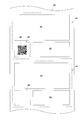
- FIG. 3 is a schematic diagram for explaining a printing area on continuous paper.
- the control unit 21 includes a computer having a CPU 23, a memory 25, and the like.
- a disk drive 27 is connected to the control unit 21.
- the disk drive 27 is configured such that a storage medium 29 is detachable.
- the storage medium 29 stores a program P described later. This program P is loaded into the memory 25 from the storage medium 29 via the disk drive 27.
- the control unit 21 performs processing described later by executing the program P loaded in the memory 25 by the CPU 23.
- the control unit 21 includes the CPU 23 and the memory 25 as described above. Functionally, the control unit 21 includes a bar code image from the print data acquisition unit 29, the decoding processing unit 31, and the bar code area quality determination unit 33. A part related to the inspection is configured.
- the print data acquisition unit 29 acquires print data from an external computer (not shown) given to the inkjet printing apparatus 3.
- the print data is, for example, data for printing information as shown in FIG. 3 in the print area PA of the continuous paper WP.
- the print area PA will be described using a credit card usage statement as an example.
- the print area PA includes a detail print area SA on which usage details are printed, a comment print area CA disposed below the printed information area, and a barcode BM disposed on the side thereof. It is composed of a barcode printing area BA to be printed.
- the bar code BM is obtained by encoding character information indicating a URL of a site for browsing details of usage details on the web, for example.
- the two-dimensional barcode is a barcode BM, but a one-dimensional barcode may be used.
- the print area PA is set as described above, even if the print area PA is the same, the bar code print area BA is displayed by the credit card user due to the presence of a customer whose URL is not encoded.
- the barcode BM may or may not be printed. Printing with the same format but different contents is called variable printing. Therefore, even if the print area PA is photographed by the inspection unit 17 and the presence / absence of the barcode BM is uniformly inspected in the barcode print area BA, the barcode is not always present. Can not.
- the barcode BM may be stained due to blurring or ink dripping during printing, or may not be printed due to a malfunction of the printing unit 13. Of course, the barcode BM that has not been printed cannot be read correctly by the credit card user who has received the usage statement. Therefore, such a barcode BM in the barcode printing area BA needs to be determined as an error.
- the decoding processing unit 31 decodes (decodes) the barcode BM. Specifically, the print data obtained by printing the print area PA is received from the print data acquisition unit 29, and after the bar code print area BA is cut out, the bar code BM therein is decoded. In addition, after receiving the photographing data from the inspection unit 17 and cutting out the barcode print area BA in it, the barcode BM in the barcode is decoded.
- the bar code area pass / fail judgment unit 33 compares the decoding result of the bar code BM of the photographic data and the bar code BM of the print data received from the decode processing unit 31 and, based on the comparison, the bar code on the continuous paper WP. The quality of printing in the printing area BA is determined.
- the bar code area pass / fail judgment unit 33 judges that the printing of the bar code printing area BA is abnormal, the bar code area pass / fail judgment unit 33 gives an error to the operator via the notification unit 35 such as a lamp, a buzzer, or a display device (not shown). Announce the occurrence.
- the inspection unit 17 described above corresponds to the “imaging unit” in the present invention
- the print data acquisition unit 29 corresponds to the “print data acquisition unit” in the present invention
- the decode processing unit 31 in the present invention “decode processing unit”.
- the barcode area quality determination unit 33 corresponds to “barcode area quality determination means” in the present invention.
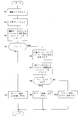
- FIG. 4 is a flowchart showing the operation of the barcode image inspection apparatus.
- Step S1 The decode processing unit 31 inputs the shooting data of the print area PA of the continuous paper WP that has been printed from the inspection unit 17.
- Step S2 The print data acquisition unit 29 inputs print data obtained by printing the print area PA of the continuous paper WP that has been printed.
- Steps S3 and S4 The decode processing unit 31 cuts out the barcode print area BA for the photographic data, and decodes the barcode BM therein.
- This decoding result (data decoding processing result) is A.
- Steps S5 and S6 The decode processing unit 31 cuts out the barcode print area BA for the print data, and decodes the barcode BM therein. Note that this decoding result (print decoding processing result) is B.
- Step S7 The bar code area pass / fail judgment unit 33 branches the process according to the comparison between A and B of the decoding result.
- Step S10 In step S9, if the decoding result of the barcode BM of the print data is empty, it indicates that the barcode BM is not printed in the barcode printing area BA. Therefore, since the barcode BM as a result of printing matches the barcode BM of the print data used for printing and is empty, it is determined to be normal.
- Step S11 In step S9, if it is determined that the barcode BM decoding result of the print data is not empty and some image exists, the decoding result is some character information (for example, URL), so that it is normal. judge.
- the decoding result is some character information (for example, URL), so that it is normal. judge.
- the decoding processing unit 31 obtains the print decoding processing result A from the barcode printing area BA photographed by the inspection unit 17, and the decoding processing unit 31 from the printing data obtained by the printing data unit 29. Thus, a data decoding process result B is obtained.
- the barcode area quality determination unit 33 determines the quality of printing for the barcode printing area BA based on the comparison between the print decoding processing result A and the data decoding processing result B. Since the quality of printing is determined by comparing the decoding result of the printing result and its data, it is not determined that there is an error when the barcode is not printed in variable printing. Therefore, even if the format is the same, the inspection accuracy can be increased in variable printing corresponding to the case where the barcode is printed and the case where the barcode is not printed.
- FIG. 5 is a block diagram functionally illustrating the control unit according to the second embodiment.
- the overall configuration is the same as that of the first embodiment (FIG. 1) described above.
- the same components of the control unit 21 are denoted by the same reference numerals, and detailed description thereof is omitted.
- the control unit 21 constituting the barcode image inspection apparatus BC according to the second embodiment includes a print data acquisition unit 29, a decoding processing unit 31A, a barcode area quality determination unit 33A, and a barcode image presence / absence determination unit 41. It has.
- the decode processing unit 31A acquires the shooting data from the inspection unit 17, cuts out the barcode print area BA, and decodes the barcode BM therein. However, if the barcode BM cannot be decoded, an error is output.
- the barcode image presence / absence determination unit 41 determines whether or not a barcode exists based on whether or not there is an image having a predetermined shape in the barcode printing area BA in the print data received from the print data acquisition unit 29. Specifically, the barcode print area BA is cut out from the print data, and the barcode BM is decoded. The determination result resulting in an error due to the inability to decode and the decoding result are provided to the bar code area pass / fail determination unit 33A.
- the bar code area pass / fail judgment unit 33A determines that the printing on the bar code printing area BA has been normally performed when the decoding process in the decoding processing unit 31A is normally performed. If the decoding process in the decoding processing unit 31A fails, the quality of printing in the barcode printing area BA is determined based on the barcode presence / absence determination in the barcode image presence / absence determining unit 41.
- the decoding processing unit 31A described above corresponds to the “decoding processing unit” in the present invention
- the barcode area quality determination unit 33A corresponds to the “barcode area quality determination unit” in the present invention
- the barcode image presence / absence determination unit. 41 corresponds to “barcode image presence / absence determining means”.
- FIG. 4 is a flowchart showing the operation of the barcode image inspection apparatus.
- Step T1 The decode processing unit 31A takes in the image data of the printing area PA of the continuous paper WP that has been printed from the inspection unit 17.
- Step T2 The print data acquisition unit 29 acquires the print data used for printing the print area PA of the continuous paper WP that has been printed.
- Step T3, T4 The decode processing unit 31A cuts out the barcode print area BA in the print area PA and decodes the barcode BM in the barcode print area BA. Then, the process branches according to the decoding result.
- Step T5 If the decoding is normally performed and no error occurs in step T3, the printed barcode BM is free of dirt, character information can be obtained, and the barcode printing area BA is not empty. Represents that. Therefore, in this case, the barcode area quality determination unit 33A determines that printing is normal.
- Step T6, T7 On the other hand, if the decoding is not normally performed in step T3 and an error occurs, the barcode print area BA of the print data is cut out, and the barcode BM in the area is decoded.
- Step T8 The bar code area pass / fail judgment unit 33A branches the process based on the result of the decoding process in step T7.
- Step T9 In step T8, if the result of the decoding process is an error or if it is blank, this means that there is no barcode BM in the barcode print area BA of the print data. Therefore, it is determined that printing is normal.
- Step T10 In step T8, if the result of the decoding process is neither error nor blank, the barcode BM exists in the barcode printing area BA of the print data, but the barcode printing area BA on the printed continuous paper WP. Has a barcode BM that cannot be normally decoded. Therefore, in this case, it is determined that printing is abnormal. Then, the notification unit 35 notifies the error.
- the decoding processing unit 31A performs decoding processing from the barcode printing area BA photographed by the inspection unit 17. As a result, if the decoding process fails, the print data acquisition unit 29 acquires the print data.
- the barcode area quality determination unit 33A determines that the printing on the barcode printing area BA of the continuous paper WP is normal.
- the barcode area pass / fail judgment unit 33A determines whether the continuous paper WP is based on the presence / absence of an image having a predetermined shape corresponding to the barcode by the barcode image presence / absence judgment unit 41. The quality of printing for the barcode printing area BA is determined. Even if the decoding process fails, if there is no barcode BM image, it is not determined as an error. Therefore, the inspection accuracy can be increased even in variable printing.
- the present invention is not limited to the above embodiment, and can be modified as follows.
- the barcode image inspection apparatus BC in the inkjet printing system is taken as an example, but the present invention can also be applied to apparatuses other than the inkjet system.
- the credit card usage details are given as an example of variable printing, but the present invention is not limited to this.
- it can be applied to variable printing related to barcode printing such as mobile phone usage details and life insurance details.
- the continuous paper WP is taken as an example of the print medium.
- the present invention is not limited to this, and can be applied to a print medium such as a resin film. .
Landscapes
- Physics & Mathematics (AREA)
- General Physics & Mathematics (AREA)
- Engineering & Computer Science (AREA)
- Theoretical Computer Science (AREA)
- Accessory Devices And Overall Control Thereof (AREA)
Abstract
検査部17によって撮影されたバーコード印刷領域からデコード処理部31により印刷デコード処理結果を得るとともに、印刷データ部29により得られた印刷データからデコード処理部31によりデータデコード処理結果を得る。バーコード領域良否判定部33は、印刷デコード処理結果とデータデコード処理結果との比較に基づいて、バーコード印刷領域に対する印刷の良否を判定する。印刷結果とそのデータとのそれぞれのデコード結果の比較により印刷の良否判定を行うので、バリアブル印刷においてバーコードが印刷されていない場合にはエラーとの判定を行わない。したがって、バリアブル印刷においても検査精度を高めることができる。
Description
本発明は、紙などの印刷媒体に印刷されたバーコードの印刷状態を検査するバーコード画像検査装置及びその方法並びにそのプログラムに関する。
従来、この種の装置として、印刷されたバーコードを光学系で撮影する撮像素子と、撮影した画像に対して画像復元フィルタによるフィルタリングを行ってバーコードのデコードを行うフィルタ処理部と、フィルタ処理部の結果に基づいてバーコード画像のデコードの適否を判定する判定部とを備え、バーコードのデコード結果が適切であった場合にだけバーコードのデコードデータを出力するものがある(例えば、特許文献1参照)。
しかしながら、このような構成を有する従来例の場合には、次のような問題がある。
すなわち、従来の装置は、印刷時にバーコードに小さな汚れが付着することに起因するデコードエラーと、元々バーコードが印刷されていないことに起因するデコードエラーとを区別できない。バーコードが印刷されていない場合には、本来はデコードエラーにするべきではないにも関わらずエラーとされているので、デコード画像の検査精度が低くなるという問題がある。なお、最近は、同一の書式であっても、必要に応じてバーコードを印刷する場合としない場合とに対応して印刷を行うバリアブル印刷が行われるので、検査精度を高める需要が高い。
すなわち、従来の装置は、印刷時にバーコードに小さな汚れが付着することに起因するデコードエラーと、元々バーコードが印刷されていないことに起因するデコードエラーとを区別できない。バーコードが印刷されていない場合には、本来はデコードエラーにするべきではないにも関わらずエラーとされているので、デコード画像の検査精度が低くなるという問題がある。なお、最近は、同一の書式であっても、必要に応じてバーコードを印刷する場合としない場合とに対応して印刷を行うバリアブル印刷が行われるので、検査精度を高める需要が高い。
本発明は、このような事情に鑑みてなされたものであって、同一の書式であっても必要に応じて、バーコードを印刷する場合としない場合とに対応したバリアブル印刷であっても検査精度を高めることができるバーコード画像検査装置及びその方法並びにそのプログラムを提供することを目的とする。
本発明は、このような目的を達成するために、次のような構成をとる。
すなわち、本発明は、印刷媒体に印刷されているバーコードの検査を行うバーコード画像検査装置であって、前記印刷媒体に対してバーコードが印刷されるバーコード印刷領域を含むように撮影する撮影手段と、前記印刷媒体に印刷を行った印刷データを取得する印刷データ取得手段と、前記撮影手段によって撮影された前記バーコード印刷領域のうち、バーコードに対してデコード処理を行い、印刷デコード処理結果を取得するとともに、前記印刷媒体に印刷を行った印刷データのバーコードに対してデコード処理を行い、データデコード処理結果を取得するデコード手段と、前記印刷デコード処理結果と前記データデコード処理結果との比較に基づいて、前記バーコード印刷領域に対する印刷の良否を判定するバーコード領域良否判定手段と、を備えていることを特徴とするものである。
すなわち、本発明は、印刷媒体に印刷されているバーコードの検査を行うバーコード画像検査装置であって、前記印刷媒体に対してバーコードが印刷されるバーコード印刷領域を含むように撮影する撮影手段と、前記印刷媒体に印刷を行った印刷データを取得する印刷データ取得手段と、前記撮影手段によって撮影された前記バーコード印刷領域のうち、バーコードに対してデコード処理を行い、印刷デコード処理結果を取得するとともに、前記印刷媒体に印刷を行った印刷データのバーコードに対してデコード処理を行い、データデコード処理結果を取得するデコード手段と、前記印刷デコード処理結果と前記データデコード処理結果との比較に基づいて、前記バーコード印刷領域に対する印刷の良否を判定するバーコード領域良否判定手段と、を備えていることを特徴とするものである。
[作用・効果]本発明によれば、撮影手段によって撮影されたバーコード印刷領域からデコード手段により印刷デコード処理結果を得るとともに、印刷データ取得手段により得られた印刷データからデコード手段によりデータデコード処理結果を得る。バーコード領域良否判定手段は、印刷デコード処理結果とデータデコード処理結果との比較に基づいて、バーコード印刷領域に対する印刷の良否を判定する。印刷結果とそのデータとのそれぞれのデコード結果の比較により印刷の良否判定を行うので、同一の書式であっても必要に応じて、バーコードを印刷する場合としない場合とに対応したバリアブル印刷においてバーコードが印刷されていない場合にはエラーとの判定を行わない。したがって、バリアブル印刷においても検査精度を高めることができる。
また、本発明において、前記バーコード領域良否判定手段は、前記印刷デコード処理結果と前記データデコード処理結果とが不一致である場合には、前記バーコード印刷領域の印刷は異常であると判定することが好ましい。
バーコード領域良否判定手段は、印刷デコード処理結果とデータデコード処理結果とが不一致である場合には、印刷データにはないものがバーコード印刷領域に印刷されていることや、印刷データにはあるがバーコード印刷領域には印刷されていないことを示すので、バーコード印刷領域の印刷が異常であると判定する。
また、本発明において、前記バーコード領域良否判定手段は、前記印刷デコード処理結果と前記データデコード処理結果とが一致であって、前記データデコード処理結果が空である場合には、前記バーコード印刷領域の印刷は正常であると判定することが好ましい。
バーコード領域良否判定手段は、印刷デコード処理結果とデータデコード処理結果とが一致であって、データデコード処理結果が空である場合には、バーコード印刷領域が意図的に空白とされているので、バーコード印刷領域の印刷が正常であると判定する。
また、本発明において、前記バーコード領域良否判定手段は、前記印刷デコード処理結果と前記データデコード処理結果とが一致であって、前記データデコード処理結果が空でない場合には、前記バーコード印刷領域の印刷は正常であると判定することが好ましい。
バーコード領域良否判定手段は、印刷デコード処理結果とデータデコード処理結果とが一致であって、データデコード処理結果が空でない場合には、バーコード印刷領域に何らかの画像が意図的に印刷されているので、バーコード印刷領域の印刷は正常であると判定する。
また、本発明は、印刷媒体に印刷されているバーコードの検査を行うバーコード画像検査装置であって、前記印刷媒体に対してバーコードが印刷されるバーコード印刷領域を含むように撮影する撮影手段と、前記撮影手段によって撮影された前記バーコード印刷領域におけるバーコードに対してデコード処理を行うデコード手段と、前記デコード手段によるデコード処理が失敗した場合、前記印刷媒体に印刷を行った印刷データを取得する印刷データ取得手段と、前記印刷データのうち、前記バーコード印刷領域に所定形状の画像が存在するか否かを判定するバーコード画像存否判定手段と、前記デコード手段によるデコード処理が成功した場合には、前記印刷媒体の前記バーコード印刷領域に対する印刷が正常であると判定し、前記デコード手段によるデコード処理が失敗した場合には、前記バーコード画像存否判定手段によるバーコードの画像の存否に基づいて、前記印刷媒体の前記バーコード印刷領域に対する印刷の良否を判定するバーコード領域良否判定手段と、を備えていることを特徴とするものである。
[作用・効果]本発明によれば、撮影手段によって撮影されたバーコード印刷領域からデコード手段によりデコード処理を行う。その結果、デコード処理が失敗した場合には、印刷データ取得手段により印刷データを取得する。バーコード領域良否判定手段は、デコード手段によるデコード処理が成功した場合には、印刷媒体のバーコード印刷領域に対する印刷が正常であると判定する。一方、バーコード領域良否判定手段は、デコード手段によるデコード処理が失敗した場合には、バーコード画像存否判定手段によるバーコード相当の所定形状の画像の存否に基づいて、印刷媒体のバーコード印刷領域に対する印刷の良否を判定する。デコード処理が失敗しても、バーコード印刷領域にバーコードの画像が存在しない場合には、エラーとの判定を行わない。したがって、同一の書式であっても必要に応じて、バーコードを印刷する場合としない場合とに対応したバリアブル印刷においても検査精度を高めることができる。
また、本発明において、前記バーコード領域良否判定手段は、前記デコード手段によるデコードが失敗し、かつ、前記バーコード画像存否判定手段によりバーコードの画像が存在しないと判定された場合には、前記印刷媒体における前記バーコード印刷領域の印刷は正常であると判定することが好ましい。
バーコード領域良否判定手段は、デコード手段によるデコードが失敗し、かつ、バーコード画像存否判定手段によりバーコード相当の所定形状の画像が存在しないと判定された場合には、バーコード印刷領域が意図的に空白とされているので、バーコード印刷領域の印刷が正常であると判定する。
また、本発明において、前記バーコード領域良否判定手段は、前記デコード手段によるデコードが失敗し、かつ、前記バーコード画像存否判定手段によりバーコードの画像が存在すると判定された場合には、前記印刷媒体における前記バーコード印刷領域の印刷は異常であると判定することが好ましい。
バーコード領域良否判定手段は、デコード手段によるデコードが失敗し、かつ、バーコード画像存否判定手段によりバーコード相当の所定形状の画像が存在すると判定された場合には、バーコード印刷領域にバーコードを意図的に印刷しようとしていたので、印刷媒体におけるバーコード印刷領域の印刷は異常であると判定する。
また、請求項8に記載の発明は、印刷媒体に印刷されているバーコードの検査を行うバーコード画像検査方法であって、前記印刷媒体に対してバーコードが印刷されるバーコード印刷領域を含むように撮影する過程と、前記印刷媒体に印刷を行った印刷データを取得する過程と、撮影された前記バーコード印刷領域のバーコードに対してデコード処理を行い、印刷デコード処理結果を取得するとともに、前記印刷媒体に印刷を行った印刷データのバーコードに対してデコード処理を行い、データデコード処理結果を取得する過程と、前記印刷デコード処理結果と前記データデコード処理結果との比較に基づいて、前記印刷媒体の前記バーコード印刷領域に対する印刷の良否を判定する過程と、を備えていることを特徴とするものである。
[作用・効果]本発明によれば、バーコード印刷領域を含むように撮影し、印刷データを取得し、撮影されたバーコードに対してデコード処理を行い、印刷デコード処理結果を取得するとともに、印刷データのバーコードに対してデコード処理を行い、データデコード処理結果を取得する。印刷デコード処理結果とデータデコード処理結果との比較に基づいて、印刷媒体のバーコード印刷領域に対する印刷の良否を判定する。印刷結果とそのデータとのそれぞれのデコード結果の比較により印刷の良否判定を行うので、バリアブル印刷においてバーコードが印刷されていない場合にはエラーとの判定を行わない。したがって、同一の書式であっても必要に応じて、バーコードを印刷する場合としない場合とに対応したバリアブル印刷においても検査精度を高めることができる。
また、本発明は、印刷媒体に印刷されているバーコードの検査を行うバーコード画像検査方法であって、前記印刷媒体に対してバーコードが印刷されるバーコード印刷領域を含むように撮影する過程と、撮影された前記バーコード印刷領域におけるバーコードに対してデコード処理を行う過程と、前記デコード処理が失敗した場合、前記印刷媒体に印刷を行った印刷データを取得する過程と、前記印刷データのうち、前記バーコード印刷領域に所定形状の画像が存在するか否かを判定する過程と、前記デコード処理が成功した場合には、前記印刷媒体の前記バーコード印刷領域に対する印刷が正常であると判定し、前記デコード処理が失敗した場合には、前記バーコード相当の画像の存否に基づいて、前記印刷媒体の前記バーコード印刷領域に対する印刷の良否を判定する過程と、を備えていることを特徴とするものである。
[作用・効果]本発明によれば、バーコード印刷領域を含むように撮影し、撮影されたバーコード印刷領域におけるバーコードに対してデコード処理を行い、デコード処理が失敗した場合、印刷媒体に印刷を行った印刷データを取得し、印刷データのうち、バーコード印刷領域に所定形状の画像が存在するか否かを判定する。デコード処理が成功した場合には、印刷媒体のバーコード印刷領域に対する印刷が正常であると判定し、デコード処理が失敗した場合には、バーコード相当の画像の存否に基づいて、印刷媒体のバーコード印刷領域に対する印刷の良否を判定する。デコード処理が失敗しても、バーコードの画像が存在しない場合には、エラーとの判定を行わない。したがって、同一の書式であっても必要に応じて、バーコードを印刷する場合としない場合とに対応したバリアブル印刷においても検査精度を高めることができる。
本発明に係るバーコード画像検査装置によれば、撮影手段によって撮影されたバーコード印刷領域からデコード手段により印刷デコード処理結果を得るとともに、印刷データ取得手段により得られた印刷データからデコード手段によりデータデコード処理結果を得る。バーコード領域良否判定手段は、印刷デコード処理結果とデータデコード処理結果との比較に基づいて、バーコード印刷領域に対する印刷の良否を判定する。印刷結果とそのデータとのそれぞれのデコード結果の比較により印刷の良否判定を行うので、バリアブル印刷においてバーコードが印刷されていない場合にはエラーとの判定を行わない。したがって、同一の書式であっても必要に応じて、バーコードを印刷する場合としない場合とに対応したバリアブル印刷においても検査精度を高めることができる。
以下に本発明に係るバーコード画像検査装置を備えた装置として、インクジェット印刷システムを例にとって説明する。
以下、図面を参照して本発明の実施例1について説明する。
図1は、実施例1に係るバーコード画像検査装置を備えたインクジェット印刷システムの全体を示す概略構成図である。
図1は、実施例1に係るバーコード画像検査装置を備えたインクジェット印刷システムの全体を示す概略構成図である。
実施例1に係るインクジェット印刷システムは、給紙部1と、インクジェット印刷装置3と、排紙部5とを備えている。
給紙部1は、ロール状の連続紙WPを水平軸周りに回転可能に保持し、インクジェット印刷装置3に対して連続紙WPを巻き出して供給する。インクジェット印刷装置3は、連続紙WPに対して印刷を行う。排紙部5は、インクジェット印刷装置3で印刷された連続紙WPを水平軸周りに巻き取る。連続紙WPの供給側を上流とし、連続紙WPの排紙側を下流とすると、給紙部1はインクジェット印刷装置3の上流側に配置され、排紙部5はインクジェット印刷装置3の下流側に配置されている。
インクジェット印刷装置3は、給紙部1からの連続紙WPを取り込むための駆動ローラ7を上流側に備えている。駆動ローラ7によって給紙部1から巻き出された連続紙WPは、複数個の搬送ローラ9に沿って下流側の排紙部5に向かって搬送される。最下流の搬送ローラ9と排紙部5との間には、駆動ローラ11が配置されている。この駆動ローラ11は、搬送ローラ9上を搬送されている連続紙WPを排紙部5に向かって送り出す。
インクジェット印刷装置3は、駆動ローラ7と駆動ローラ11との間に、印刷ユニット13と、乾燥部15と、検査部17とを上流側からその順で備えている。乾燥部15は、印刷ユニット13によって印刷された部分の乾燥を行う。検査部17は、印刷された部分に汚れや抜け等がないかを検査するための撮影用カメラを備えている。
印刷ユニット13は、インク滴を吐出する印刷ヘッド19を備えている。印刷ユニット13は、連続紙WPの搬送方向に沿って複数個配置されているのが一般的である。例えば、ブラック(K)、シアン(C)、マゼンタ(M)、イエロー(Y)について個別に4個の印刷ユニット13を備えている。しかし、以下においては、発明の理解を容易にするために、1個の印刷ユニット13だけを備えているものとして説明する。また、印刷ユニット13は、連続紙WPの幅方向(紙面の奥手前方向)における印刷領域を移動することなく印刷できるだけの印刷ヘッド19を複数個備えている。つまり、本実施例におけるインクジェット印刷装置3は、印刷ヘッド19が連続紙WPの搬送方向に直交する方向に主走査のために移動することがなく、位置固定のままで連続紙WPを副走査方向に送りながら連続紙WPに対して印刷を行う。なお、このような構成は、1パス機と呼ばれる。
駆動ローラ7,11、印刷ユニット13、乾燥部15、検査部17は、制御部21によって統括的に制御される。制御部21は、CPUやメモリなどを備えており、連続紙WPに印刷する画像のデータを印刷ユニット13に送るとともに、印刷速度や印刷ユニット13におけるインク滴の吐出速度等に応じて駆動ローラ7,11の駆動速度を操作したり、バーコード画像の検査を行ったりする。上記の構成のうち、制御部21と、検査部17とがバーコード画像検査装置BCを構成している。
次に、図2及び図3を参照する。なお、図2は、実施例1における制御部を機能的に示したブロック図であり、図3は、連続紙における印刷領域の説明に供する模式図である。
制御部21は、CPU23やメモリ25等を備えたコンピュータで構成されている。制御部21には、ディスクドライブ27が接続されている。このディスクドライブ27は、記憶メディア29を着脱自在に構成されている。記憶メディア29は、後述するプログラムPが記憶されている。このプログラムPは、記憶メディア29からディスクドライブ27を介してメモリ25にロードされる。制御部21は、メモリ25にロードされたプログラムPをCPU23で実行することによって、後述する処理を行う。
制御部21は、上述したようにCPU23やメモリ25で構成されているが、機能的には、印刷データ取得部29と、デコード処理部31と、バーコード領域良否判定部33とからバーコード画像検査に係る部分が構成されている。
印刷データ取得部29は、インクジェット印刷装置3に与えられる外部コンピュータ(不図示)からの印刷データを取得する。印刷データは、例えば、連続紙WPの印刷領域PA内に図3に示すような情報を印刷するためのデータである。ここで印刷領域PAについて、クレジットカードの利用明細書を例にとって説明する。印刷領域PAは、利用明細が印刷される明細印刷領域SAと、その下方に配置された、クレジットカードに関する情報が印刷されるコメント印刷領域CAと、その側方に配置された、バーコードBMが印刷されるバーコード印刷領域BAとから構成されている。バーコードBMは、例えば、利用明細の詳細等をウエブ上で閲覧するためのサイトのURLを示す文字情報をコード化したものである。図3においては、二次元バーコートをバーコードBMとしているが、一次元バーコードであってもよい。
印刷領域PAは、上述したように設定されているが、同じ印刷領域PAであっても、クレジットカードの利用者によってバーコード印刷領域BAは、URLがコード化されていない取引先の存在等に応じて、バーコードBMが印刷されたりされなかったりすることがある。このような書式が同じでも内容が異なる印刷は、バリアブル印刷と呼ばれている。したがって、印刷領域PAを検査部17で撮影して、バーコード印刷領域BAにおいてバーコードBMの有無を一律に検査しても、必ずバーコードが存在するとは限らないので、正しい検査を行うことはできない。また、バーコードBMは、印刷時におけるすれやインク滴垂れなどに起因した汚れが付着したり、印刷ユニット13の不具合により印刷がされなかったりすることがある。印刷されなかったバーコードBMは無論のこと、汚れが付着したバーコードBMは、利用明細を受け取ったクレジットカードの利用者が正しく読み取ることができない。したがって、バーコード印刷領域BAにおけるこのようなバーコードBMはエラーとして判定する必要がある。
デコード処理部31は、バーコードBMをデコード(復号化)する。具体的には、印刷領域PAを印刷した印刷データを印刷データ取得部29から受け取り、そのなかのバーコード印刷領域BAを切り出し処理した後に、その中のバーコードBMをデコードする。また、検査部17から撮影データを受け取り、その中のバーコード印刷領域BAを切り出し処理した後に、その中のバーコードBMに対してデコードを行う。
バーコード領域良否判定部33は、デコード処理部31から受け取った、撮影データのバーコードBMと、印刷データのバーコードBMとのデコード結果を比較し、その比較に基づいて連続紙WPにおけるバーコード印刷領域BAの印刷の良否を判定する。
また、バーコード領域良否判定部33は、バーコード印刷領域BAの印刷が異常であると判定した場合には、ランプやブザーあるいは図示しない表示装置などの報知部35を介してオペレータに対して異常発生を報知する。
なお、上述した検査部17が本発明における「撮影手段」に相当し、印刷データ取得部29が本発明における「印刷データ取得手段」に相当し、デコード処理部31が本発明における「デコード処理手段」に相当し、バーコード領域良否判定部33が本発明における「バーコード領域良否判定手段」に相当する。
ここで図4を参照して、上述したバーコード画像検査装置BCの動作について説明する。なお、図4は、バーコード画像検査装置の動作を示すフローチャートである。
ステップS1
デコード処理部31は、印刷を終えた連続紙WPの印刷領域PAの撮影データを検査部17から入力する。
デコード処理部31は、印刷を終えた連続紙WPの印刷領域PAの撮影データを検査部17から入力する。
ステップS2
印刷データ取得部29は、印刷を終えた連続紙WPの印刷領域PAを印刷した印刷データを入力する。
印刷データ取得部29は、印刷を終えた連続紙WPの印刷領域PAを印刷した印刷データを入力する。
ステップS3,S4
デコード処理部31は、撮影データについてバーコード印刷領域BAを切り出し処理し、その中のバーコードBMをデコードする。なお、このデコード結果(データデコード処理結果)をAとする。
デコード処理部31は、撮影データについてバーコード印刷領域BAを切り出し処理し、その中のバーコードBMをデコードする。なお、このデコード結果(データデコード処理結果)をAとする。
ステップS5,S6
デコード処理部31は、印刷データについてバーコード印刷領域BAを切り出し処理し、その中のバーコードBMをデコードする。なお、このデコード結果(印刷デコード処理結果)をBとする。
デコード処理部31は、印刷データについてバーコード印刷領域BAを切り出し処理し、その中のバーコードBMをデコードする。なお、このデコード結果(印刷デコード処理結果)をBとする。
ステップS7
バーコード領域良否判定部33は、上記のデコード結果のAとBとの比較に応じて処理を分岐する。
バーコード領域良否判定部33は、上記のデコード結果のAとBとの比較に応じて処理を分岐する。
ステップS8
バーコード領域良否判定部33は、ステップS7における比較の結果、A=Bでない場合には、このステップS8に分岐し、デコード結果がエラーであるとして、報知部35を介してエラーの報知を行う。つまり、印刷した結果のバーコードBMと、印刷に用いた印刷データのバーコードBMとが不一致であるので、印刷時に何らかの汚れがバーコードBMに付着したり、バーコードBMが正常に印刷されなかったりしたと判定する。
バーコード領域良否判定部33は、ステップS7における比較の結果、A=Bでない場合には、このステップS8に分岐し、デコード結果がエラーであるとして、報知部35を介してエラーの報知を行う。つまり、印刷した結果のバーコードBMと、印刷に用いた印刷データのバーコードBMとが不一致であるので、印刷時に何らかの汚れがバーコードBMに付着したり、バーコードBMが正常に印刷されなかったりしたと判定する。
ステップS9
バーコード領域良否判定部33は、ステップS7における比較の結果、A=Bである場合には、このステップS9に分岐し、印刷データのバーコードBMのデコード結果が空であるか否かによって処理を分岐する。
バーコード領域良否判定部33は、ステップS7における比較の結果、A=Bである場合には、このステップS9に分岐し、印刷データのバーコードBMのデコード結果が空であるか否かによって処理を分岐する。
ステップS10
ステップS9において、印刷データのバーコードBMのデコード結果が空であった場合には、バーコード印刷領域BAにバーコードBMが印刷されていないことを表す。したがって、印刷した結果のバーコードBMと、印刷に用いた印刷データのバーコードBMとが一致し、かつ空であるので、正常であると判定する。
ステップS9において、印刷データのバーコードBMのデコード結果が空であった場合には、バーコード印刷領域BAにバーコードBMが印刷されていないことを表す。したがって、印刷した結果のバーコードBMと、印刷に用いた印刷データのバーコードBMとが一致し、かつ空であるので、正常であると判定する。
ステップS11
ステップS9において、印刷データのバーコードBMのデコード結果が空ではなく、何らかの画像が存在したと判断された場合には、そのデコード結果が何らかの文字情報(例えばURL)であるので、正常であると判定する。
ステップS9において、印刷データのバーコードBMのデコード結果が空ではなく、何らかの画像が存在したと判断された場合には、そのデコード結果が何らかの文字情報(例えばURL)であるので、正常であると判定する。
上述した実施例1によると、検査部17によって撮影されたバーコード印刷領域BAからデコード処理部31により印刷デコード処理結果Aを得るとともに、印刷データ部29により得られた印刷データからデコード処理部31によりデータデコード処理結果Bを得る。バーコード領域良否判定部33は、印刷デコード処理結果Aとデータデコード処理結果Bとの比較に基づいて、バーコード印刷領域BAに対する印刷の良否を判定する。印刷結果とそのデータとのそれぞれのデコード結果の比較により印刷の良否判定を行うので、バリアブル印刷においてバーコードが印刷されていない場合にはエラーとの判定を行わない。したがって、同一の書式であっても必要に応じて、バーコードを印刷する場合としない場合とに対応したバリアブル印刷においても検査精度を高めることができる。
次に、図面を参照して本発明の実施例2について説明する。
図5は、実施例2における制御部を機能的に示したブロック図である。なお、全体の構成は、上述した実施例1(図1)と同じである。また、制御部21のうち、共通する構成については同符号を付すことで詳細な説明については省略する。
図5は、実施例2における制御部を機能的に示したブロック図である。なお、全体の構成は、上述した実施例1(図1)と同じである。また、制御部21のうち、共通する構成については同符号を付すことで詳細な説明については省略する。
実施例2のバーコード画像検査装置BCを構成している制御部21は、印刷データ取得部29と、デコード処理部31Aと、バーコード領域良否判定部33Aと、バーコード画像存否判定部41とを備えている。
デコード処理部31Aは、検査部17から撮影データを取得し、バーコード印刷領域BAを切り出し処理するとともに、そのなかのバーコードBMをデコードする。但し、バーコードBMがデコードできなかった場合には、エラーを出力する。
バーコード画像存否判定部41は、印刷データ取得部29から受け取った印刷データのうち、バーコード印刷領域BAのなかに所定形状の画像があるか否かによってバーコードの存否を判定する。具体的には、印刷データからバーコード印刷領域BAを切り出し、そのなかのバーコードBMをデコードする。デコード不可によりエラーとなった判定結果及びデコード結果は、バーコード領域良否判定部33Aに与えられる。
バーコード領域良否判定部33Aは、デコード処理部31Aにおけるデコード処理が正常に行われた場合には、バーコード印刷領域BAに対する印刷が正常に行われたと判断する。また、デコード処理部31Aにおけるデコード処理が失敗した場合には、バーコード画像存否判定部41におけるバーコードの存否判定に基づいて、バーコード印刷領域BAにおける印刷の良否を判定する。
なお、上述したデコード処理部31Aが本発明における「デコード処理手段」に相当し、バーコード領域良否判定部33Aが本発明における「バーコード領域良否判定手段」に相当し、バーコード画像存否判定部41が「バーコード画像存否判定手段」に相当する。
ここで図6を参照して、上述したバーコード画像検査装置BCの動作について説明する。なお、図4は、バーコード画像検査装置の動作を示すフローチャートである。
ステップT1
デコード処理部31Aは、印刷を終えた連続紙WPの印刷領域PAの撮影データを検査部17から取り込む。
デコード処理部31Aは、印刷を終えた連続紙WPの印刷領域PAの撮影データを検査部17から取り込む。
ステップT2
印刷データ取得部29は、印刷を終えた連続紙WPの印刷領域PAを印刷するために使用された印刷データを取得する。
印刷データ取得部29は、印刷を終えた連続紙WPの印刷領域PAを印刷するために使用された印刷データを取得する。
ステップT3,T4
デコード処理部31Aは、印刷領域PAのうちのバーコード印刷領域BAを切り出し処理するとともに、バーコード印刷領域BAのバーコードBMをデコードする。そして、デコードの結果に応じて処理を分岐する。
デコード処理部31Aは、印刷領域PAのうちのバーコード印刷領域BAを切り出し処理するとともに、バーコード印刷領域BAのバーコードBMをデコードする。そして、デコードの結果に応じて処理を分岐する。
ステップT5
ステップT3においてデコードが正常に行われ、エラーが生じなかった場合には、印刷した結果のバーコードBMに汚れ等がなく、文字情報を得ることができ、バーコード印刷領域BAも空ではなかったことを表す。したがって、この場合には、バーコード領域良否判定部33Aは印刷が正常であると判定する。
ステップT3においてデコードが正常に行われ、エラーが生じなかった場合には、印刷した結果のバーコードBMに汚れ等がなく、文字情報を得ることができ、バーコード印刷領域BAも空ではなかったことを表す。したがって、この場合には、バーコード領域良否判定部33Aは印刷が正常であると判定する。
ステップT6,T7
一方、ステップT3においてデコードが正常に行われず、エラーとなった場合には、印刷データのバーコード印刷領域BAを切り出し処理し、その領域内のバーコードBMに対してデコード処理を施す。
一方、ステップT3においてデコードが正常に行われず、エラーとなった場合には、印刷データのバーコード印刷領域BAを切り出し処理し、その領域内のバーコードBMに対してデコード処理を施す。
ステップT8
バーコード領域良否判定部33Aは、ステップT7におけるデコード処理の結果に基づいて処理を分岐する。
バーコード領域良否判定部33Aは、ステップT7におけるデコード処理の結果に基づいて処理を分岐する。
ステップT9
ステップT8において、デコード処理の結果がエラーである場合または空白であった場合には、印刷データのバーコード印刷領域BAにバーコードBMがなかったことを表す。したがって、印刷は正常であったと判定する。
ステップT8において、デコード処理の結果がエラーである場合または空白であった場合には、印刷データのバーコード印刷領域BAにバーコードBMがなかったことを表す。したがって、印刷は正常であったと判定する。
ステップT10
ステップT8において、デコード処理の結果がエラーまたは空白でもなかった場合には、印刷データのバーコード印刷領域BAにバーコードBMが存在しているが、印刷された連続紙WPにおけるバーコード印刷領域BAには正常にデコードできない状態のバーコードBMがあることになる。したがって、この場合には、印刷は異常であると判定する。そして、報知部35によりエラーの報知を行う。
ステップT8において、デコード処理の結果がエラーまたは空白でもなかった場合には、印刷データのバーコード印刷領域BAにバーコードBMが存在しているが、印刷された連続紙WPにおけるバーコード印刷領域BAには正常にデコードできない状態のバーコードBMがあることになる。したがって、この場合には、印刷は異常であると判定する。そして、報知部35によりエラーの報知を行う。
上述した実施例2によると、検査部17によって撮影されたバーコード印刷領域BAからデコード処理部31Aによりデコード処理を行う。その結果、デコード処理が失敗した場合には、印刷データ取得部29により印刷データを取得する。バーコード領域良否判定部33Aは、デコード処理部31Aによるデコード処理が成功した場合には、連続紙WPのバーコード印刷領域BAに対する印刷が正常であると判定する。一方、バーコード領域良否判定部33Aは、デコード処理部31Aによるデコード処理が失敗した場合には、バーコード画像存否判定部41によるバーコード相当の所定形状の画像の存否に基づいて、連続紙WPのバーコード印刷領域BAに対する印刷の良否を判定する。デコード処理が失敗しても、バーコードBMの画像が存在しない場合には、エラーとの判定を行わない。したがって、バリアブル印刷においても検査精度を高めることができる。
本発明は、上記実施形態に限られることはなく、下記のように変形実施することができる。
(1)上述した各実施例1,2では、インクジェット印刷システムにおけるバーコード画像検査装置BCを例にとったが、本発明はインクジェット方式の以外の装置にも適用することができる。
(2)上述した各実施例1,2では、バリアブル印刷の例としてクレジットカードの利用明細をあげたが、本発明はこれに限定されない。例えば、携帯電話の利用明細、生命保険の明細などのバーコード印刷に係るバリアブル印刷であれば適用できる。
(3)上述した各実施例1,2では、印刷媒体として連続紙WPを例にとったが、本発明はこれに限定されるものではなく、例えば、樹脂フィルムなどの印刷媒体にも適用できる。
3 … インクジェット印刷装置
WP … 連続紙
13 … 印刷ユニット
21 … 制御部
BC … バーコード画像検査装置
29 … 印刷データ取得部
31,31A … デコード処理部
33,33A … バーコード領域良否判定部
35 … 報知部
41 … バーコード画像存否判定部
PA … 印刷領域
SA … 明細印刷領域
CA … コメント印刷領域
BM … バーコード
BA … バーコード印刷領域
WP … 連続紙
13 … 印刷ユニット
21 … 制御部
BC … バーコード画像検査装置
29 … 印刷データ取得部
31,31A … デコード処理部
33,33A … バーコード領域良否判定部
35 … 報知部
41 … バーコード画像存否判定部
PA … 印刷領域
SA … 明細印刷領域
CA … コメント印刷領域
BM … バーコード
BA … バーコード印刷領域
Claims (11)
- 印刷媒体に印刷されているバーコードの検査を行うバーコード画像検査装置であって、
前記印刷媒体に対してバーコードが印刷されるバーコード印刷領域を含むように撮影する撮影手段と、
前記印刷媒体に印刷を行った印刷データを取得する印刷データ取得手段と、
前記撮影手段によって撮影された前記バーコード印刷領域のうち、バーコードに対してデコード処理を行い、印刷デコード処理結果を取得するとともに、前記印刷媒体に印刷を行った印刷データのバーコードに対してデコード処理を行い、データデコード処理結果を取得するデコード手段と、
前記印刷デコード処理結果と前記データデコード処理結果との比較に基づいて、前記バーコード印刷領域に対する印刷の良否を判定するバーコード領域良否判定手段と、
を備えていることを特徴とするバーコード画像検査装置。 - 請求項1に記載のバーコード画像検査装置において、
前記バーコード領域良否判定手段は、前記印刷デコード処理結果と前記データデコード処理結果とが不一致である場合には、前記バーコード印刷領域の印刷は異常であると判定することを特徴とするバーコード画像検査装置。 - 請求項1に記載のバーコード画像検査装置において、
前記バーコード領域良否判定手段は、前記印刷デコード処理結果と前記データデコード処理結果とが一致であって、前記データデコード処理結果が空である場合には、前記バーコード印刷領域の印刷は正常であると判定することを特徴とするバーコード画像検査装置。 - 請求項1に記載のバーコード画像検査装置において、
前記バーコード領域良否判定手段は、前記印刷デコード処理結果と前記データデコード処理結果とが一致であって、前記データデコード処理結果が空でない場合には、前記バーコード印刷領域の印刷は正常であると判定することを特徴とするバーコード画像検査装置。 - 印刷媒体に印刷されているバーコードの検査を行うバーコード画像検査装置であって、
前記印刷媒体に対してバーコードが印刷されるバーコード印刷領域を含むように撮影する撮影手段と、
前記撮影手段によって撮影された前記バーコード印刷領域におけるバーコードに対してデコード処理を行うデコード手段と、
前記デコード手段によるデコード処理が失敗した場合、前記印刷媒体に印刷を行った印刷データを取得する印刷データ取得手段と、
前記印刷データのうち、前記バーコード印刷領域に所定形状の画像が存在するか否かを判定するバーコード画像存否判定手段と、
前記デコード手段によるデコード処理が成功した場合には、前記印刷媒体の前記バーコード印刷領域に対する印刷が正常であると判定し、前記デコード手段によるデコード処理が失敗した場合には、前記バーコード画像存否判定手段によるバーコードの画像の存否に基づいて、前記印刷媒体の前記バーコード印刷領域に対する印刷の良否を判定するバーコード領域良否判定手段と、
を備えていることを特徴とするバーコード画像検査装置。 - 請求項5に記載のバーコード画像検査装置において、
前記バーコード領域良否判定手段は、前記デコード手段によるデコードが失敗し、かつ、前記バーコード画像存否判定手段によりバーコードの画像が存在しないと判定された場合には、前記印刷媒体における前記バーコード印刷領域の印刷は正常であると判定することを特徴とするバーコード画像検査装置。 - 請求項5に記載のバーコード画像検査装置において、
前記バーコード領域良否判定手段は、前記デコード手段によるデコードが失敗し、かつ、前記バーコード画像存否判定手段によりバーコードの画像が存在すると判定された場合には、前記印刷媒体における前記バーコード印刷領域の印刷は異常であると判定することを特徴とするバーコード画像検査装置。 - 印刷媒体に印刷されているバーコードの検査を行うバーコード画像検査方法であって、
前記印刷媒体に対してバーコードが印刷されるバーコード印刷領域を含むように撮影する過程と、
前記印刷媒体に印刷を行った印刷データを取得する過程と、
撮影された前記バーコード印刷領域のバーコードに対してデコード処理を行い、印刷デコード処理結果を取得するとともに、前記印刷媒体に印刷を行った印刷データのバーコードに対してデコード処理を行い、データデコード処理結果を取得する過程と、
前記印刷デコード処理結果と前記データデコード処理結果との比較に基づいて、前記印刷媒体の前記バーコード印刷領域に対する印刷の良否を判定する過程と、
を備えていることを特徴とするバーコード画像検査方法。 - 印刷媒体に印刷されているバーコードの検査を行うバーコード画像検査方法であって、
前記印刷媒体に対してバーコードが印刷されるバーコード印刷領域を含むように撮影する過程と、
撮影された前記バーコード印刷領域におけるバーコードに対してデコード処理を行う過程と、
前記デコード処理が失敗した場合、前記印刷媒体に印刷を行った印刷データを取得する過程と、
前記印刷データのうち、前記バーコード印刷領域に所定形状の画像が存在するか否かを判定する過程と、
前記デコード処理が成功した場合には、前記印刷媒体の前記バーコード印刷領域に対する印刷が正常であると判定し、前記デコード処理が失敗した場合には、前記バーコード相当の画像の存否に基づいて、前記印刷媒体の前記バーコード印刷領域に対する印刷の良否を判定する過程と、
を備えていることを特徴とするバーコード画像検査方法。 - 印刷媒体に印刷されているバーコードの検査をコンピュータによって行うバーコード画像検査プログラムであって、
前記コンピュータのCPUがメモリにおいて実行することにより、
前記印刷媒体に対してバーコードが印刷されるバーコード印刷領域を含むように撮影する機能と、
前記印刷媒体に印刷を行った印刷データを取得する機能と、
撮影された前記バーコード印刷領域のうち、バーコードに対してデコード処理を行い、印刷デコード処理結果を取得するとともに、前記印刷媒体に印刷を行った印刷データのバーコードに対してデコード処理を行い、データデコード処理結果を取得する機能と、
前記印刷デコード処理結果と前記データデコード処理結果との比較に基づいて、前記印刷媒体の前記バーコード印刷領域に対する印刷の良否を判定する機能と、
を前記コンピュータに実現させることを特徴とするバーコード画像検査プログラム。 - 印刷媒体に印刷されているバーコードの検査をコンピュータによって行うバーコード画像検査プログラムであって、
前記コンピュータのCPUがメモリにおいて実行することにより、
前記印刷媒体に対してバーコードが印刷されるバーコード印刷領域を含むように撮影する機能と、
撮影された前記バーコード印刷領域におけるバーコードに対してデコード処理を行う機能と、
前記デコード処理が失敗した場合、前記印刷媒体に印刷を行った印刷データを取得する機能と、
前記バーコード印刷領域に所定形状の画像が存在するか否かを判定する機能と、
前記デコード処理が成功した場合には、前記印刷媒体の前記バーコード印刷領域に対する印刷が正常であると判定し、前記デコード処理が失敗した場合には、前記バーコード相当の画像の存否に基づいて、前記印刷媒体の前記バーコード印刷領域に対する印刷の良否を判定する機能と、
を前記コンピュータに実現させることを特徴とするバーコード画像検査プログラム。
Applications Claiming Priority (2)
| Application Number | Priority Date | Filing Date | Title |
|---|---|---|---|
| JP2013-201745 | 2013-09-27 | ||
| JP2013201745A JP6100661B2 (ja) | 2013-09-27 | 2013-09-27 | バーコード画像検査装置及びその方法並びにそのプログラム |
Publications (1)
| Publication Number | Publication Date |
|---|---|
| WO2015045453A1 true WO2015045453A1 (ja) | 2015-04-02 |
Family
ID=52742613
Family Applications (1)
| Application Number | Title | Priority Date | Filing Date |
|---|---|---|---|
| PCT/JP2014/060123 Ceased WO2015045453A1 (ja) | 2013-09-27 | 2014-04-07 | バーコード画像検査装置及びその方法並びにそのプログラム |
Country Status (2)
| Country | Link |
|---|---|
| JP (1) | JP6100661B2 (ja) |
| WO (1) | WO2015045453A1 (ja) |
Cited By (3)
| Publication number | Priority date | Publication date | Assignee | Title |
|---|---|---|---|---|
| WO2018073938A1 (ja) * | 2016-10-20 | 2018-04-26 | 日本電気株式会社 | 個体識別装置 |
| WO2018073937A1 (ja) * | 2016-10-20 | 2018-04-26 | 日本電気株式会社 | 個体識別装置 |
| JP2023034478A (ja) * | 2021-08-31 | 2023-03-13 | キヤノン株式会社 | 検査装置および検査方法 |
Families Citing this family (1)
| Publication number | Priority date | Publication date | Assignee | Title |
|---|---|---|---|---|
| JP7500513B2 (ja) | 2021-08-31 | 2024-06-17 | キヤノン株式会社 | 印刷物の検査装置および方法 |
Citations (4)
| Publication number | Priority date | Publication date | Assignee | Title |
|---|---|---|---|---|
| JPS5475807U (ja) * | 1977-11-05 | 1979-05-30 | ||
| JPH05307627A (ja) * | 1991-09-18 | 1993-11-19 | Nippondenso Co Ltd | バーコード端末装置 |
| WO1998027512A1 (en) * | 1996-12-16 | 1998-06-25 | C.I.M. Card Identification Machines S.P.A. | Method for personalizing flat supports |
| JP2008236177A (ja) * | 2007-03-19 | 2008-10-02 | Ricoh Co Ltd | 画像形成装置、画像形成方法、およびそのプログラム |
-
2013
- 2013-09-27 JP JP2013201745A patent/JP6100661B2/ja active Active
-
2014
- 2014-04-07 WO PCT/JP2014/060123 patent/WO2015045453A1/ja not_active Ceased
Patent Citations (4)
| Publication number | Priority date | Publication date | Assignee | Title |
|---|---|---|---|---|
| JPS5475807U (ja) * | 1977-11-05 | 1979-05-30 | ||
| JPH05307627A (ja) * | 1991-09-18 | 1993-11-19 | Nippondenso Co Ltd | バーコード端末装置 |
| WO1998027512A1 (en) * | 1996-12-16 | 1998-06-25 | C.I.M. Card Identification Machines S.P.A. | Method for personalizing flat supports |
| JP2008236177A (ja) * | 2007-03-19 | 2008-10-02 | Ricoh Co Ltd | 画像形成装置、画像形成方法、およびそのプログラム |
Cited By (9)
| Publication number | Priority date | Publication date | Assignee | Title |
|---|---|---|---|---|
| WO2018073938A1 (ja) * | 2016-10-20 | 2018-04-26 | 日本電気株式会社 | 個体識別装置 |
| WO2018073937A1 (ja) * | 2016-10-20 | 2018-04-26 | 日本電気株式会社 | 個体識別装置 |
| JPWO2018073938A1 (ja) * | 2016-10-20 | 2019-07-11 | 日本電気株式会社 | 個体識別装置 |
| JPWO2018073937A1 (ja) * | 2016-10-20 | 2019-07-11 | 日本電気株式会社 | 個体識別装置 |
| US20190333209A1 (en) * | 2016-10-20 | 2019-10-31 | Nec Corporation | Individual identifying device |
| US10839505B2 (en) | 2016-10-20 | 2020-11-17 | Nec Corporation | Individual identifying device |
| US11263740B2 (en) | 2016-10-20 | 2022-03-01 | Nec Corporation | Individual identifying device |
| JP2023034478A (ja) * | 2021-08-31 | 2023-03-13 | キヤノン株式会社 | 検査装置および検査方法 |
| JP7746072B2 (ja) | 2021-08-31 | 2025-09-30 | キヤノン株式会社 | 検査装置および検査方法 |
Also Published As
| Publication number | Publication date |
|---|---|
| JP2015069317A (ja) | 2015-04-13 |
| JP6100661B2 (ja) | 2017-03-22 |
Similar Documents
| Publication | Publication Date | Title |
|---|---|---|
| EP3509286B1 (en) | Methods, apparatuses, and systems for detecting printing defects and contaminated components of a printer | |
| US9126404B2 (en) | Ink jet recording apparatus and method for detecting faulty discharge in ink jet recording apparatus | |
| JP5334902B2 (ja) | 印刷装置およびカメラ位置調整方法 | |
| CN101096156B (zh) | 记录装置及搬送方法 | |
| US20180021969A1 (en) | Cutting apparatus | |
| JP6100661B2 (ja) | バーコード画像検査装置及びその方法並びにそのプログラム | |
| WO2009119030A1 (ja) | 画像記録装置 | |
| US10800193B2 (en) | Nozzle operating situation checking method for inkjet printing apparatus, an inkjet printing apparatus, and a program thereof | |
| US9681006B2 (en) | Print control apparatus, print control method, and program | |
| CN113436180A (zh) | 生产线上喷射码的检测方法、装置、系统、设备和介质 | |
| EP2848921B1 (en) | Substrate defect detection mechanism | |
| JP5879140B2 (ja) | 印刷画像検査装置及び印刷画像検査方法 | |
| JP2013244706A (ja) | 印字ユニット | |
| US8789913B2 (en) | Printing apparatus | |
| JP6111901B2 (ja) | 液体吐出装置、液体吐出方法及び該液体吐出装置に用いられるプログラム | |
| JP2010066822A (ja) | 検査装置 | |
| US9266364B2 (en) | Printing associated plots in registration | |
| JP2014066618A (ja) | 画像検査装置及び画像検査方法並びに画像検査プログラム | |
| JP6285766B2 (ja) | 記録装置及び記録方法 | |
| JP7797832B2 (ja) | 印刷装置および印刷方法 | |
| JP5374632B2 (ja) | 印刷装置 | |
| JP2014189385A (ja) | シート搬送装置、印刷機、シート搬送方法及びプログラム | |
| JP6235285B2 (ja) | 印刷装置及び印刷制御装置並びに印刷制御方法 | |
| JP2025033294A (ja) | 印刷装置、印刷制御方法、および印刷制御プログラム | |
| JP2013159047A (ja) | 不良ノズル検出装置、不良ノズル検出方法、および、コンピュータープログラム |
Legal Events
| Date | Code | Title | Description |
|---|---|---|---|
| 121 | Ep: the epo has been informed by wipo that ep was designated in this application |
Ref document number: 14849359 Country of ref document: EP Kind code of ref document: A1 |
|
| NENP | Non-entry into the national phase |
Ref country code: DE |
|
| 122 | Ep: pct application non-entry in european phase |
Ref document number: 14849359 Country of ref document: EP Kind code of ref document: A1 |