WO2015045353A1 - 画像診断装置及びその制御方法及びプログラム及びコンピュータ可読記憶媒体 - Google Patents
画像診断装置及びその制御方法及びプログラム及びコンピュータ可読記憶媒体 Download PDFInfo
- Publication number
- WO2015045353A1 WO2015045353A1 PCT/JP2014/004848 JP2014004848W WO2015045353A1 WO 2015045353 A1 WO2015045353 A1 WO 2015045353A1 JP 2014004848 W JP2014004848 W JP 2014004848W WO 2015045353 A1 WO2015045353 A1 WO 2015045353A1
- Authority
- WO
- WIPO (PCT)
- Prior art keywords
- light
- catheter
- imaging core
- line data
- image
- Prior art date
- Legal status (The legal status is an assumption and is not a legal conclusion. Google has not performed a legal analysis and makes no representation as to the accuracy of the status listed.)
- Ceased
Links
Images





Classifications
-
- A—HUMAN NECESSITIES
- A61—MEDICAL OR VETERINARY SCIENCE; HYGIENE
- A61B—DIAGNOSIS; SURGERY; IDENTIFICATION
- A61B8/00—Diagnosis using ultrasonic, sonic or infrasonic waves
- A61B8/52—Devices using data or image processing specially adapted for diagnosis using ultrasonic, sonic or infrasonic waves
- A61B8/5215—Devices using data or image processing specially adapted for diagnosis using ultrasonic, sonic or infrasonic waves involving processing of medical diagnostic data
- A61B8/5223—Devices using data or image processing specially adapted for diagnosis using ultrasonic, sonic or infrasonic waves involving processing of medical diagnostic data for extracting a diagnostic or physiological parameter from medical diagnostic data
-
- A—HUMAN NECESSITIES
- A61—MEDICAL OR VETERINARY SCIENCE; HYGIENE
- A61B—DIAGNOSIS; SURGERY; IDENTIFICATION
- A61B5/00—Measuring for diagnostic purposes; Identification of persons
- A61B5/0059—Measuring for diagnostic purposes; Identification of persons using light, e.g. diagnosis by transillumination, diascopy, fluorescence
- A61B5/0062—Arrangements for scanning
- A61B5/0066—Optical coherence imaging
-
- A—HUMAN NECESSITIES
- A61—MEDICAL OR VETERINARY SCIENCE; HYGIENE
- A61B—DIAGNOSIS; SURGERY; IDENTIFICATION
- A61B5/00—Measuring for diagnostic purposes; Identification of persons
- A61B5/0059—Measuring for diagnostic purposes; Identification of persons using light, e.g. diagnosis by transillumination, diascopy, fluorescence
- A61B5/0073—Measuring for diagnostic purposes; Identification of persons using light, e.g. diagnosis by transillumination, diascopy, fluorescence by tomography, i.e. reconstruction of 3D images from 2D projections
-
- A—HUMAN NECESSITIES
- A61—MEDICAL OR VETERINARY SCIENCE; HYGIENE
- A61B—DIAGNOSIS; SURGERY; IDENTIFICATION
- A61B5/00—Measuring for diagnostic purposes; Identification of persons
- A61B5/0059—Measuring for diagnostic purposes; Identification of persons using light, e.g. diagnosis by transillumination, diascopy, fluorescence
- A61B5/0082—Measuring for diagnostic purposes; Identification of persons using light, e.g. diagnosis by transillumination, diascopy, fluorescence adapted for particular medical purposes
- A61B5/0084—Measuring for diagnostic purposes; Identification of persons using light, e.g. diagnosis by transillumination, diascopy, fluorescence adapted for particular medical purposes for introduction into the body, e.g. by catheters
-
- A—HUMAN NECESSITIES
- A61—MEDICAL OR VETERINARY SCIENCE; HYGIENE
- A61B—DIAGNOSIS; SURGERY; IDENTIFICATION
- A61B5/00—Measuring for diagnostic purposes; Identification of persons
- A61B5/68—Arrangements of detecting, measuring or recording means, e.g. sensors, in relation to patient
- A61B5/6846—Arrangements of detecting, measuring or recording means, e.g. sensors, in relation to patient specially adapted to be brought in contact with an internal body part, i.e. invasive
- A61B5/6847—Arrangements of detecting, measuring or recording means, e.g. sensors, in relation to patient specially adapted to be brought in contact with an internal body part, i.e. invasive mounted on an invasive device
- A61B5/6852—Catheters
-
- A—HUMAN NECESSITIES
- A61—MEDICAL OR VETERINARY SCIENCE; HYGIENE
- A61B—DIAGNOSIS; SURGERY; IDENTIFICATION
- A61B5/00—Measuring for diagnostic purposes; Identification of persons
- A61B5/68—Arrangements of detecting, measuring or recording means, e.g. sensors, in relation to patient
- A61B5/6846—Arrangements of detecting, measuring or recording means, e.g. sensors, in relation to patient specially adapted to be brought in contact with an internal body part, i.e. invasive
- A61B5/6867—Arrangements of detecting, measuring or recording means, e.g. sensors, in relation to patient specially adapted to be brought in contact with an internal body part, i.e. invasive specially adapted to be attached or implanted in a specific body part
- A61B5/6876—Blood vessel
-
- A—HUMAN NECESSITIES
- A61—MEDICAL OR VETERINARY SCIENCE; HYGIENE
- A61B—DIAGNOSIS; SURGERY; IDENTIFICATION
- A61B5/00—Measuring for diagnostic purposes; Identification of persons
- A61B5/72—Signal processing specially adapted for physiological signals or for diagnostic purposes
- A61B5/7221—Determining signal validity, reliability or quality
-
- A—HUMAN NECESSITIES
- A61—MEDICAL OR VETERINARY SCIENCE; HYGIENE
- A61B—DIAGNOSIS; SURGERY; IDENTIFICATION
- A61B8/00—Diagnosis using ultrasonic, sonic or infrasonic waves
- A61B8/08—Clinical applications
- A61B8/0891—Clinical applications for diagnosis of blood vessels
-
- A—HUMAN NECESSITIES
- A61—MEDICAL OR VETERINARY SCIENCE; HYGIENE
- A61B—DIAGNOSIS; SURGERY; IDENTIFICATION
- A61B8/00—Diagnosis using ultrasonic, sonic or infrasonic waves
- A61B8/12—Diagnosis using ultrasonic, sonic or infrasonic waves in body cavities or body tracts, e.g. by using catheters
-
- A—HUMAN NECESSITIES
- A61—MEDICAL OR VETERINARY SCIENCE; HYGIENE
- A61B—DIAGNOSIS; SURGERY; IDENTIFICATION
- A61B8/00—Diagnosis using ultrasonic, sonic or infrasonic waves
- A61B8/44—Constructional features of the ultrasonic, sonic or infrasonic diagnostic device
- A61B8/4416—Constructional features of the ultrasonic, sonic or infrasonic diagnostic device related to combined acquisition of different diagnostic modalities, e.g. combination of ultrasound and X-ray acquisitions
-
- A—HUMAN NECESSITIES
- A61—MEDICAL OR VETERINARY SCIENCE; HYGIENE
- A61B—DIAGNOSIS; SURGERY; IDENTIFICATION
- A61B8/00—Diagnosis using ultrasonic, sonic or infrasonic waves
- A61B8/44—Constructional features of the ultrasonic, sonic or infrasonic diagnostic device
- A61B8/4444—Constructional features of the ultrasonic, sonic or infrasonic diagnostic device related to the probe
- A61B8/445—Details of catheter construction
-
- A—HUMAN NECESSITIES
- A61—MEDICAL OR VETERINARY SCIENCE; HYGIENE
- A61B—DIAGNOSIS; SURGERY; IDENTIFICATION
- A61B8/00—Diagnosis using ultrasonic, sonic or infrasonic waves
- A61B8/44—Constructional features of the ultrasonic, sonic or infrasonic diagnostic device
- A61B8/4444—Constructional features of the ultrasonic, sonic or infrasonic diagnostic device related to the probe
- A61B8/4461—Features of the scanning mechanism, e.g. for moving the transducer within the housing of the probe
-
- A—HUMAN NECESSITIES
- A61—MEDICAL OR VETERINARY SCIENCE; HYGIENE
- A61B—DIAGNOSIS; SURGERY; IDENTIFICATION
- A61B8/00—Diagnosis using ultrasonic, sonic or infrasonic waves
- A61B8/44—Constructional features of the ultrasonic, sonic or infrasonic diagnostic device
- A61B8/4483—Constructional features of the ultrasonic, sonic or infrasonic diagnostic device characterised by features of the ultrasound transducer
- A61B8/4494—Constructional features of the ultrasonic, sonic or infrasonic diagnostic device characterised by features of the ultrasound transducer characterised by the arrangement of the transducer elements
-
- A—HUMAN NECESSITIES
- A61—MEDICAL OR VETERINARY SCIENCE; HYGIENE
- A61B—DIAGNOSIS; SURGERY; IDENTIFICATION
- A61B8/00—Diagnosis using ultrasonic, sonic or infrasonic waves
- A61B8/46—Ultrasonic, sonic or infrasonic diagnostic devices with special arrangements for interfacing with the operator or the patient
- A61B8/461—Displaying means of special interest
-
- A—HUMAN NECESSITIES
- A61—MEDICAL OR VETERINARY SCIENCE; HYGIENE
- A61B—DIAGNOSIS; SURGERY; IDENTIFICATION
- A61B8/00—Diagnosis using ultrasonic, sonic or infrasonic waves
- A61B8/52—Devices using data or image processing specially adapted for diagnosis using ultrasonic, sonic or infrasonic waves
- A61B8/5207—Devices using data or image processing specially adapted for diagnosis using ultrasonic, sonic or infrasonic waves involving processing of raw data to produce diagnostic data, e.g. for generating an image
-
- A—HUMAN NECESSITIES
- A61—MEDICAL OR VETERINARY SCIENCE; HYGIENE
- A61B—DIAGNOSIS; SURGERY; IDENTIFICATION
- A61B8/00—Diagnosis using ultrasonic, sonic or infrasonic waves
- A61B8/52—Devices using data or image processing specially adapted for diagnosis using ultrasonic, sonic or infrasonic waves
- A61B8/5215—Devices using data or image processing specially adapted for diagnosis using ultrasonic, sonic or infrasonic waves involving processing of medical diagnostic data
- A61B8/5238—Devices using data or image processing specially adapted for diagnosis using ultrasonic, sonic or infrasonic waves involving processing of medical diagnostic data for combining image data of patient, e.g. merging several images from different acquisition modes into one image
- A61B8/5261—Devices using data or image processing specially adapted for diagnosis using ultrasonic, sonic or infrasonic waves involving processing of medical diagnostic data for combining image data of patient, e.g. merging several images from different acquisition modes into one image combining images from different diagnostic modalities, e.g. ultrasound and X-ray
-
- A—HUMAN NECESSITIES
- A61—MEDICAL OR VETERINARY SCIENCE; HYGIENE
- A61B—DIAGNOSIS; SURGERY; IDENTIFICATION
- A61B8/00—Diagnosis using ultrasonic, sonic or infrasonic waves
- A61B8/13—Tomography
- A61B8/14—Echo-tomography
-
- A—HUMAN NECESSITIES
- A61—MEDICAL OR VETERINARY SCIENCE; HYGIENE
- A61B—DIAGNOSIS; SURGERY; IDENTIFICATION
- A61B8/00—Diagnosis using ultrasonic, sonic or infrasonic waves
- A61B8/42—Details of probe positioning or probe attachment to the patient
- A61B8/4272—Details of probe positioning or probe attachment to the patient involving the acoustic interface between the transducer and the tissue
- A61B8/4281—Details of probe positioning or probe attachment to the patient involving the acoustic interface between the transducer and the tissue characterised by sound-transmitting media or devices for coupling the transducer to the tissue
-
- A—HUMAN NECESSITIES
- A61—MEDICAL OR VETERINARY SCIENCE; HYGIENE
- A61B—DIAGNOSIS; SURGERY; IDENTIFICATION
- A61B8/00—Diagnosis using ultrasonic, sonic or infrasonic waves
- A61B8/46—Ultrasonic, sonic or infrasonic diagnostic devices with special arrangements for interfacing with the operator or the patient
- A61B8/461—Displaying means of special interest
- A61B8/463—Displaying means of special interest characterised by displaying multiple images or images and diagnostic data on one display
-
- A—HUMAN NECESSITIES
- A61—MEDICAL OR VETERINARY SCIENCE; HYGIENE
- A61B—DIAGNOSIS; SURGERY; IDENTIFICATION
- A61B8/00—Diagnosis using ultrasonic, sonic or infrasonic waves
- A61B8/54—Control of the diagnostic device
Definitions
- the present invention relates to an image diagnostic apparatus, a control method thereof, a program, and a computer-readable storage medium.
- Image diagnostic apparatuses in particular, apparatuses for acquiring images of blood vessel lumens include intravascular ultrasonic diagnostic apparatus (IVUS: IntraVascular Ultra Sound) and optical coherence tomography diagnostic apparatus (OCT: Optical Coherence Tomography).
- IVUS IntraVascular Ultra Sound
- OCT optical coherence tomography diagnostic apparatus
- an imaging core including a configuration for emitting ultrasonic waves or light and a configuration for receiving reflected waves or light from the blood vessel tissue is housed in a catheter sheath.
- OCT can obtain a high-resolution image of the luminal surface of the blood vessel, but can only obtain an image from the luminal surface of the blood vessel to a relatively shallow tissue.
- the image resolution obtained is lower than that of OCT, but conversely, an image of vascular tissue deeper than that of OCT can be obtained. Therefore, recently, an image diagnostic apparatus combining an IVUS function and an OCT function (an image diagnostic apparatus including an ultrasonic transmission / reception unit capable of transmitting / receiving ultrasonic waves and an optical transmission / reception unit capable of transmitting / receiving light) is also proposed. (For example, see Patent Documents 1 and 2).
- a liquid may be contained between the imaging core and the catheter sheath as a transmission medium for signals transmitted and received by the imaging core.
- a liquid may be contained between the imaging core and the catheter sheath as a transmission medium for signals transmitted and received by the imaging core.
- liquid closer to the refractive index of the optical member or the catheter sheath than the refractive index of air it is possible to reduce the light refraction at the interface between the optical member and the catheter sheath. This is because.
- the provision of a hole for venting air at the tip of the catheter sheath may cause inconvenience. It is a problem of blood inflow into the catheter sheath in a pull-back process that can be performed after the tip of the catheter sheath is positioned in the blood vessel to be diagnosed. In the pull-back process, the imaging core is pulled along its rotation axis while rotating, so that the inside of the catheter sheath has a negative pressure relative to the outside of the catheter sheath. It is a problem that blood flows in. In addition, when an intravascular catheter is left for a long time, blood may flow into the catheter sheath without performing a pullback process due to blood pressure in the blood vessel.
- Blood that has flowed into the catheter sheath can be eliminated by re-injecting a liquid that has little effect on the human body, such as physiological saline, from the rear end of the catheter sheath, as in priming. It is necessary to know that blood is flowing into the catheter sheath.
- the present invention has been made in view of the above problems.
- a technique for detecting that air or blood other than the transparent liquid has entered the catheter sheath and notifying the user with the diagnostic imaging apparatus is provided.
- the diagnostic imaging apparatus has the following configuration. That is, In order to transmit the light from the light source toward the vascular tissue, as well as containing an imaging core having an optical transmission / reception unit for receiving reflected light from the vascular tissue, using a catheter having an opening at the tip, An image for reconstructing a blood vessel image based on interference light data obtained by converting interference light obtained by combining the measurement light obtained by rotating the imaging core and the reference light separated from the light from the light source into an electrical signal A diagnostic device, Line data generating means for generating line data from the interference light data in the radial direction from the rotational center position of the imaging core; Determining whether foreign matter other than the predetermined liquid is mixed between the imaging core and the inner surface of the catheter from the distribution of signal intensity values in the line data generated by the line data generating means Means, And a display means for displaying a message indicating that the contamination is detected when the determination result of the determination means indicates the contamination.
- FIG. 1 is a diagram showing an external configuration of an image diagnostic apparatus 100 according to an embodiment of the present invention.
- the diagnostic imaging apparatus 100 includes a probe 101, a scanner / pullback unit 102, and an operation control device 103, and the scanner / pullback unit 102 and the operation control device 103 are connected via a connector 105. They are connected by a cable 104 containing a signal line or an optical fiber.
- the probe 101 is inserted directly into a blood vessel, transmits an ultrasonic wave based on a pulse signal and receives a reflected wave from the blood vessel, and transmitted light (measurement light). Is inserted into a blood vessel, and a catheter that houses an imaging core including an optical transmission / reception unit that continuously receives reflected light from the blood vessel is inserted. In the diagnostic imaging apparatus 100, the state inside the blood vessel is measured by using the imaging core.
- the scanner and pullback unit 102 is detachably attached to the probe 101, and operates in the axial direction and rotational direction in the blood vessel of the imaging core in the catheter inserted into the probe 101 by driving a built-in motor. Is stipulated. In addition, the scanner and pullback unit 102 acquires the reflected wave signal received by the ultrasonic transmission / reception unit in the imaging core and the reflected light received by the optical transmission / reception unit, and transmits them to the operation control device 103.
- the operation control device 103 has a function for inputting various set values and a function for processing ultrasonic data and optical interference data obtained by the measurement and displaying various blood vessel images when performing the measurement.
- 111 is a main body control unit.
- the main body control unit 111 generates line data from an ultrasonic reflected wave signal obtained by measurement, and generates an ultrasonic cross-sectional image through interpolation processing. Further, the main body control unit 111 generates interference light data by causing interference between the reflected light from the imaging core and the reference light obtained by separating the light from the light source. Based on this, line data is generated, and a blood vessel cross-sectional image based on optical interference is generated through interpolation processing.
- Reference numeral 111-1 is a printer and a DVD recorder, which prints the processing results in the main body control unit 111 or stores them as data.
- Reference numeral 112 denotes an operation panel, and the user inputs various setting values and instructions via the operation panel 112.
- Reference numeral 113 denotes an LCD monitor as a display device, which displays various cross-sectional images generated by the main body control unit 111.
- Reference numeral 114 denotes a mouse as a pointing device (coordinate input device).
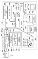
- FIG. 2 is a block configuration diagram of the diagnostic imaging apparatus 100.
- the functional configuration of the wavelength sweep type OCT will be described with reference to FIG.
- reference numeral 201 denotes a signal processing unit that controls the entire diagnostic imaging apparatus, and is composed of several circuits including a microprocessor.
- Reference numeral 210 denotes a non-volatile storage device represented by a hard disk, which stores various programs and data files executed by the signal processing unit 201.
- Reference numeral 202 denotes a memory (RAM) provided in the signal processing unit 201.
- a wavelength swept light source 203 is a light source that repeatedly generates light having a wavelength that changes within a preset range along the time axis.
- the light output from the wavelength swept light source 203 is incident on one end of the first single mode fiber 271 and transmitted toward the distal end side.
- the first single mode fiber 271 is optically coupled to the fourth single mode fiber 275 at an intermediate optical fiber coupler 272.
- the light incident on the first single mode fiber 271 and emitted from the optical fiber coupler 272 toward the front end is guided to the second single mode fiber 273 via the connector 105.
- the other end of the second single mode fiber 273 is connected to the optical rotary joint 230 in the pullback unit 102.
- the probe 101 has an adapter 101 a for connecting to the pullback unit 102. Then, the probe 101 is stably held by the pullback unit 102 by connecting the probe 101 to the pullback unit 102 by the adapter 101a. Furthermore, the end of the third single mode fiber 274 rotatably accommodated in the probe 101 is connected to the optical rotary joint 230. As a result, the second single mode fiber 273 and the third single mode fiber 274 are optically coupled. At the other end of the third single-mode fiber 274 (the head portion side of the probe 101), an optical transmission / reception unit composed of a mirror and a lens that emits light in a direction substantially perpendicular to the rotation axis (see FIG. An imaging core 250 is provided, which will be described with reference to FIG.
- the light emitted from the wavelength swept light source 203 passes through the first single mode fiber 271, the second single mode fiber 273, and the third single mode fiber 274 to the end of the third single mode fiber 274. It is guided to the provided imaging core 250.
- the optical transmission / reception unit of the image core 250 emits this light in a direction perpendicular to the axis of the fiber, receives the reflected light, and the received reflected light is led in reverse this time to the operation control device 103. returned.
- an optical path length adjustment mechanism 220 that finely adjusts the optical path length of the reference light is provided at the opposite end of the fourth single mode fiber 275 coupled to the optical fiber coupler 272.
- the optical path length variable mechanism 220 functions as an optical path length changing unit that changes the optical path length corresponding to the variation in length so that the variation in length of each probe 101 can be absorbed when the probe 101 is replaced.
- a collimating lens 225 located at the end of the fourth single mode fiber 275 is provided on a movable uniaxial stage 224 as indicated by an arrow 226 in the optical axis direction.
- the uniaxial stage 224 functions as an optical path length changing unit having a variable range of the optical path length that can absorb the variation in the optical path length of the probe 101. Further, the uniaxial stage 224 also has a function as an adjusting means for adjusting the offset. For example, even when the tip of the probe 101 is not in close contact with the surface of the living tissue, the optical path length can be minutely changed by the uniaxial stage so as to interfere with the reflected light from the surface position of the living tissue. Is possible.
- the optical path length is finely adjusted by the uniaxial stage 224, and the light reflected by the mirror 223 via the grating 221 and the lens 222 is again guided to the fourth single mode fiber 275, and the second optical fiber coupler 272 performs the second operation.
- the second optical fiber coupler 272 performs the second operation.
- the interference light received by the photodiode 204 in this way is photoelectrically converted, amplified by the amplifier 205, and then input to the demodulator 206.
- the demodulator 206 performs demodulation processing for extracting only the signal portion of the interfered light, and its output is input to the A / D converter 207 as an interference light signal.
- the A / D converter 207 samples the interference light signal for 2048 points at 90 MHz, for example, and generates one line of digital data (interference light data).
- the sampling frequency of 90 MHz is based on the assumption that about 90% of the wavelength sweep cycle (25 ⁇ sec) is extracted as 2048 digital data when the wavelength sweep repetition frequency is 40 kHz. There is no particular limitation.
- the line-by-line interference light data generated by the A / D converter 207 is input to the signal processing unit 201 and temporarily stored in the memory 202.
- the interference light data is subjected to frequency decomposition by FFT (Fast Fourier Transform) to generate data in the depth direction (line data), and this is coordinate-converted to obtain data at each position in the blood vessel.
- FFT Fast Fourier Transform
- An optical section image is constructed and output to the LCD monitor 113 at a predetermined frame rate.
- the signal processing unit 201 is further connected to an optical path length adjustment driving unit 209 and a communication unit 208.
- the signal processing unit 201 controls the position of the uniaxial stage 224 (optical path length control) via the optical path length adjustment driving unit 209.
- the communication unit 208 incorporates several drive circuits and communicates with the pullback unit 102 under the control of the signal processing unit 201. Specifically, from the encoder unit 242 for detecting the rotational position of the radial motor by supplying a driving signal to the radial scanning motor for rotating the third single mode fiber by the optical rotary joint in the pullback unit 102. And the supply of a drive signal to the linear drive unit 243 for pulling the third single mode fiber 274 at a predetermined speed.
- the above processing in the signal processing unit 201 is also realized by a predetermined program being executed by a computer.
- the signal processing unit 201 drives the wavelength swept light source 203 to drive the radial scanning motor 241 and the linear driving unit 243 (hereinafter, the radial scanning motor 241 and the linear driving unit). (Light irradiation and light reception processing by driving 243 is called scanning).
- the wavelength swept light is supplied from the wavelength swept light source 203 to the imaging core 250 through the path as described above.
- the imaging core 250 at the distal end position of the probe 101 rotates and moves along the rotation axis
- the imaging core 250 rotates while moving along the blood vessel axis. Light is emitted to the blood vessel lumen surface and its reflected light is received.
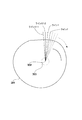
- FIG. 1 is a diagram for explaining the reconstruction processing of the cross-sectional image of the lumen surface 301 of the blood vessel in which the imaging core 250 is located.
- the measurement light is transmitted and received a plurality of times.
- data of one line in the direction of irradiation with the light can be obtained.
- 512 line data extending radially from the rotation center 302 can be obtained by transmitting and receiving light 512 times, for example, during one rotation.
- These 512 line data are dense in the vicinity of the rotation center position and become sparse with each other as the distance from the rotation center position increases.
- the pixels in the empty space of each line are generated by performing a known interpolation process, and a two-dimensional cross-sectional image that can be seen by humans is generated. Then, as shown in FIG. 4, a three-dimensional blood vessel image 402 can be obtained by connecting the generated two-dimensional cross-sectional images 401 to each other along the blood vessel axis.
- the center position of the two-dimensional cross-sectional image coincides with the rotation center position of the imaging core 250, but is not the center position of the blood vessel cross section.
- it is weak light is reflected by the lens surface of the imaging core 250, the surface of the catheter, etc., so that several concentric circles are generated with respect to the rotation center axis as indicated by reference numeral 303 in the drawing.
- Scanning using ultrasonic waves is performed simultaneously with the optical interference scanning described above. That is, while scanning and rotating the imaging core 250 while moving in the catheter sheath of the probe 101, the ultrasonic wave is emitted from the ultrasonic wave transmission / reception unit accommodated in the imagen core 250 and the reflected wave is transmitted. Perform detection. For this reason, it is necessary to generate a drive electric signal for driving the ultrasonic transmission / reception unit accommodated in the imagen core 250 and to receive an ultrasonic detection signal output from the ultrasonic transmission / reception unit.
- the ultrasonic transmission / reception control unit 232 performs transmission of the drive signal and reception of the detected signal.
- the ultrasonic transmission / reception control unit 232 and the imaging core 250 are connected via signal line cables 281, 282, and 283.
- the signal line cables 282 and 283 are electrically connected via the slip ring 231 provided in the pullback unit 102.
- the signal line cables 281 to 283 are shown as being connected by a single line, but actually they are accommodated by a plurality of signal lines.
- the ultrasonic transmission / reception control unit 232 operates under the control of the signal processing unit 201, drives the ultrasonic transmission / reception unit accommodated in the imaging core 250, and generates an ultrasonic pulse wave.
- the ultrasonic transmission / reception unit converts the reflected wave from the vascular tissue into an electric signal and supplies the electric signal to the ultrasonic transmission / reception control unit 232.
- the ultrasonic transmission / reception control unit 232 outputs the received ultrasonic signal to the amplifier 233 for amplification. Thereafter, the amplified ultrasonic signal is supplied to the signal processing unit 201 as ultrasonic data through the detector 234 and the A / D converter 235 and temporarily stored in the memory 202.
- the A / D converter 235 samples the ultrasonic signal output from the detector 454 for 200 points at 30.6 MHz to generate one line of digital data (ultrasound data).
- 30.6 MHz is assumed, but this is calculated on the assumption that 200 points are sampled at a depth of 5 mm when the sound speed is 1530 m / sec. Therefore, the sampling frequency is not particularly limited to this.
- the signal processing unit 201 generates an ultrasonic cross-sectional image at each position in the blood vessel by converting the ultrasonic data stored in the memory 202 into a gray scale.
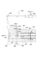
- An injection port 501 for injecting a transparent liquid 550 (such as physiological saline) into the catheter sheath is provided in the vicinity of the rear end (the end connected to the pullback portion 102) of the catheter 500.
- the catheter 500 accommodates the third single mode fiber 274 and the signal line cable 283 already described, but the rear end of the catheter 500 has a shield structure so that liquid does not leak.
- a priming hole 520 for discharging bubbles when the catheter sheath is filled with the liquid 550 is provided at the distal end portion of the catheter 500.
- the catheter sheath 510 of the catheter 500 is made of a transparent material, and accommodates an imaging core 250 that is rotatable and movable along the catheter 500.
- the imaging core 250 includes an ultrasonic transmission / reception unit 511, an optical transmission / reception unit 512, and a housing 513 that houses the ultrasonic transmission / reception unit 511.
- the housing 513 is supported by the drive shaft 514.
- the drive shaft 514 is made of a material that is flexible and can transmit rotation well.
- the drive shaft 514 includes a multi-layered close contact coil made of a metal wire such as stainless steel.
- a signal line cable 283 and a third single mode fiber 274 are accommodated in the drive shaft 514.
- the housing 513 has a notch in a part of a cylindrical metal pipe.
- the ultrasonic transmission / reception unit 511 and the optical transmission / reception unit 512 transmit and receive ultrasonic waves and light through the notch.
- the ultrasonic transmission / reception unit 511 emits ultrasonic waves toward the arrow 571a shown in the figure according to the pulse signal applied from the signal line cable 283, detects the reflected wave from the vascular tissue indicated by the arrow 571b, and electrically converts it.
- the signal is output onto the signal line cable 283 as a signal.
- the optical transmission / reception unit 512 is provided at the end of the third single mode fiber 274 and has a hemispherical shape in which a sphere is cut at an angle of approximately 45 degrees with respect to the vertical plane of FIG. The part is formed.
- the optical transmission / reception unit 512 has a hemispherical shape, and thus has a lens function.
- the light supplied via the third single mode fiber 274 is reflected by this mirror part and emitted toward the vascular tissue along the arrow 572a shown in the drawing. Then, the reflected light from the vascular tissue indicated by the arrow 572b shown in the figure is received, reflected by the mirror portion, and returned to the third single mode fiber 274.
- the pull back unit 102 drives the radial scanning motor 241 and the linear drive unit 243, so that the drive shaft 514 rotates along the arrow 573 and along the arrow 574. Moving.
- the imaging core 250 performs emission of ultrasonic waves and detection of reflected waves, and emission of light and detection of reflected light while performing rotation and movement in the axial direction.
- the catheter sheath 510 is subjected to a priming operation before the operation, that is, an operation of filling the catheter sheath 510 with the liquid 550 by injecting the liquid 550 from the liquid inlet 501 and discharging the internal air from the priming hole 520.
- a priming operation before the operation, that is, an operation of filling the catheter sheath 510 with the liquid 550 by injecting the liquid 550 from the liquid inlet 501 and discharging the internal air from the priming hole 520.
- the problem of the case where the priming operation is not sufficient and the bubbles 560 exist will be considered.
- a blood vessel image reconstruction process using optical interference and a blood vessel image reconstruction process using ultrasound are filled with a known medium (in the embodiment, physiological saline) between the catheter sheath 510 and the imaging core 250.
- the blood vessel image reconstruction process is performed on the assumption that the propagation speed of the ultrasound and light between the catheter sheath 510 and the imaging core 250 is known. If a medium other than the known medium is present between the catheter sheath 510 and the imaging core 250, the propagation speed of sound waves and light in that portion becomes unexpected, and the reconstructed image is disturbed and artifacts.
- an ultrasonic wave is almost totally reflected at the interface between a gas such as air and a liquid such as physiological saline, an image reconstructed using IVUS is significantly deteriorated.
- the light supplied to the third single mode fiber 274 is reflected by the mirror of the optical transceiver 512 and is emitted in a direction (arrow 572a) orthogonal to the moving direction of the imaging core 250 (arrow 574).
- the Light has the property of reflecting at the interface between two media with different refractive indices. Therefore, most of the light reflected by the mirror of the light transmitting / receiving unit 512 is emitted to the outside of the catheter sheath 510.
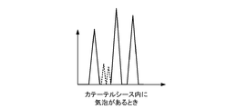
- the pixels (luminance values) constituting the line data obtained by the FFT conversion are arranged from the rotation center axis, they are as shown in FIG. 6A.
- the horizontal axis shown corresponds to the distance from the rotation center position, and the vertical axis is the luminance at that position.
- three peaks of the lens surface position of the light transmitting / receiving unit 512, the position of the inner side surface 510a of the catheter sheath 510, and the position of the outer side surface 510b are detected in the order close to the rotation center position.
- the brightness of the valley between the position of the lens surface of the portion 512 and the peak of the position of the inner surface 510a of the catheter sheath 510 is zero or substantially equal to zero.
- the reason is that the liquid 550 is transparent.
- the distance from the lens surface position of the light transmitting / receiving unit 512 to the outer surface 510b of the catheter sheath 510 corresponds to a value obtained by subtracting the distance from the center of rotation to the lens surface of the light transmitting / receiving unit 512 from the radius of the catheter.
- the three peaks up to the known range can be regarded as indicating the positions of the lens surface of the optical transceiver 512, the inner surface 510a of the catheter sheath 510, and the outer surface 510b.
- a case where a bubble 560 exists between the optical transceiver 512 and the inner surface of the catheter sheath 510 will be considered.
- at least one light passing through the lens of the light transmitting / receiving unit 512 passes through the boundary surface between the bubble 560 and the liquid 550 before reaching the inner surface 510 a of the catheter sheath 510.
- the propagation speed of light is higher in the gas than in the liquid. Therefore, when bubbles are present between the optical transceiver 512 and the inner surface of the catheter sheath 510, the time for propagation between them is shorter than when only the liquid 550 is present between them. Accordingly, the peaks indicating the positions of the inner surface 510a and the outer surface 510b of the catheter sheath 510 in FIG. 6B appear to appear at positions slightly shifted to the left (rotation center position) as compared with FIG. 6A. Therefore, in the embodiment, the conditions for specifying the peaks of the lens surface of the optical transceiver 512 and the inner surface 510a and the outer surface 510b of the catheter sheath 510 are defined as follows.
- the optical transmission / reception unit 512 is provided at the end of the third single mode fiber 274, and the light supplied to the third single mode fiber 274 is reflected first without depending on the presence or absence of bubbles.
- the position of the lens is the position of the surface of the lens of the optical transmission / reception unit 512. Therefore, among the peaks generated on the line data obtained by the FFT processing of the signal processing unit 201, the peak most generated on the rotation center side corresponds to reflection on the surface of the lens of the optical transmission / reception unit 512. Further, the distance from the rotation center to the lens surface of the optical transceiver 512 is fixed (known).
- the apparent distance from the lens surface of the light transmitting / receiving unit 512 to the outer surface 510a of the catheter sheath is maximized when only the liquid 550 is between them, and the maximum distance is the catheter sheath. It is equal to a value obtained by subtracting the distance (known) from the center of rotation to the lens surface of the optical transceiver 512 from the radius of the outer surface 510b of 510.
- the apparent distance from the surface of the lens of the light transmitting / receiving unit 512 to the outer surface 510a of the catheter sheath is minimized when there is only gas (air) between them. Accordingly, it can be considered that the peak between the maximum distance and the minimum distance indicates the outer surface 510a of the catheter sheath.
- the material of the catheter sheath 510 occupies a range corresponding to the thickness of the catheter sheath 510 from the peak position of the outer surface 510a of the catheter sheath toward the rotation center position, and no peak is generated there. Under such conditions, the peak position of the outer surface 510b of the catheter sheath 510 can be specified with sufficient accuracy. (3) When the peak position of the outer surface 510b of the catheter sheath 510 can be specified, the position separated from the rotation center position by the thickness of the catheter sheath 510 is the peak position of the inner surface 510a of the catheter sheath 510. is there.
- the HDD 210 is filled with only the liquid 550 and has no air bubbles, and a pixel value serving as a reference between the peak position of the lens surface of the optical transceiver 512 and the peak position of the inner surface 510a of the catheter sheath 510 (hereinafter referred to as a reference).
- C1, C2, ..., Cm (referred to as pixel values) are stored in advance.
- the threshold T is set to a small value, a stricter judgment standard can be set, and if the threshold T is set to a large value, a relaxed judgment standard can be set.
- the allowable range for foreign matter can be changed by the signal processing unit 201 according to the situation. For example, it can be changed by inputting the value of the threshold value T displayed on the LCD monitor 113 from the operation panel 112 or the mouse 114 through the operation control device 103.
- the above is the processing related to the detection of bubbles in the catheter 500, but when the probe 101 is actually inserted into the blood vessel of the patient and scanned, blood flows into the catheter 500 from the priming hole 520. There is also. Therefore, in the following, the reason and problems of the blood inflow will be considered.
- the pullback unit 102 is driven, so that the imaging core 250 rotates along the arrow 573 in the catheter sheath 510 and moves along the arrow 574. . Then, the imaging core 250 and the drive shaft 514 just function as pistons, and the inside of the catheter 500 becomes negative pressure. This is one of the reasons why blood flows into the catheter 500 from the priming hole 520.
- the inflow of blood into the catheter 500 is also detected, and when it is detected, a message prompting priming is displayed.
- the conditions for determining the peak position of the lens surface of the optical transmitter / receiver 512, the peak position of the inner surface 510a of the catheter sheath 510, and the peak position of the outer surface 510b are the same as the bubble detection conditions (1) to (3). It's okay. Further, it can be understood that the same algorithm as the bubble detection can be applied to the condition for determining whether or not an opaque liquid (blood) exists.
- step S701 the signal processing unit 201 waits for an input from the operation panel 112 or the mouse 114 from the user. If there is an input, it is determined in step S702 whether or not the input is an instruction indicating that the priming operation has been completed. In cases other than an instruction indicating completion of priming, the process proceeds to step S703, and the corresponding processing is performed. On the other hand, if it is an instruction input for completion of the priming operation, it is inspected in step S704 whether or not foreign matter (bubbles) actually disappears.
- step S704 Such processing is as described above, but is briefly described as follows.
- the signal processing unit 201 drives the wavelength sweep light source 203 and drives the radial scanning motor for the pullback unit 102 to rotate the imaging core 250 for a predetermined time. At this time, the linear drive unit 243 is not driven. As a result, the imaging core 250 starts rotating as indicated by an arrow 573 in FIG. However, since the linear drive unit 243 is not driven, the imaging core 250 does not move along the arrow 574.
- the signal processing unit 201 stores interference light data obtained by combining the light detected by the optical transmission / reception unit 512 of the imaging core 250 and the reference light in the memory 202, performs FFT conversion, and outputs a plurality of line data (for 360 degrees). Line data is preferred). Then, the plurality of line data are analyzed, and the position of the lens surface of the optical transmission / reception unit 512, the inner side surface 510a and the outer side surface 510a of the catheter sheath is determined for each line data according to the above-described conditions.
- the evaluation value S of the contamination of the foreign matter is obtained from the pixel group between the position indicating the lens surface of the optical transmission / reception unit 512 in the line data, the pixel group between the position indicating the inner surface 510a of the catheter sheath, and the reference pixel group. Ask. Then, it is determined whether or not the evaluation value S is larger than a preset threshold value. If even one line data larger than the threshold exists, it is determined that there is a foreign substance (bubble) in the catheter 500, and if no line data larger than the threshold exists, it is determined that there is no foreign substance.
- step S705 it is determined whether or not the foreign object inspection indicates the presence of a foreign object. If there is a foreign object, the process proceeds to step S706, a message indicating that priming is insufficient is displayed on the LCD monitor 113, and the process returns to step S701.
- the user When it is determined that there is no foreign object, the user performs various settings for pullback processing or inserts the probe 101 into the patient's blood vessel and positions the tip of the probe 101 in the coronary artery or the like.
- a pull back scan start instruction is input from the operation panel 112. In some cases, the end of processing may be input.
- step S707 When there is any instruction input from the operation panel 112 (step S707), the signal processing unit 201 determines whether the instruction is a pullback scan start instruction (step S708). The process to perform is performed in step S709.
- step S710 the signal processing unit 201 detects foreign matter (here, blood) again before starting actual pull-back processing.
- This foreign object detection processing is the same as step S704 already described, and is performed by driving the radial scanning motor without driving the linear drive unit 243 of the pullback unit 102. If it is determined in step S711 that there is a foreign object, there is a possibility that a clear image may not be obtained even if pullback scanning is performed as it is. Therefore, the process proceeds to step S712, and a message prompting priming is displayed on the LCD monitor 113. Then, the process returns to step S707.
- step S713 the process proceeds to step S713 to start the pull-back scan process. That is, the wavelength sweep light source 203 is driven and the ultrasonic transmission / reception control unit 232 is controlled to start generation and reception of ultrasonic waves.
- the radial scanning motor 241 and the linear drive unit 243 are driven with respect to the pullback unit 102 to rotate the imaging core 250 at a predetermined speed and to move at a predetermined speed by a set distance.
- the interference light data and the ultrasonic data are obtained from the A / D converters 207 and 235, they are accumulated in the memory 202.
- the signal processing unit 201 performs FFT conversion processing on the interference light data and ultrasonic data stored in the memory 202 in step S714 to construct line data, and pulls back the blood vessel axis.
- a process of generating a cross-sectional image of the entire area along the line is performed, and a process of displaying on the LCD monitor 113 is performed.
- step S715 the line data already constructed in the memory 202 is analyzed to determine whether or not a foreign substance (blood) flows into the catheter 500. This determination is substantially the same as step S704 described above. If it is determined in step S716 that foreign matter (blood) is flowing into the catheter 500, the image obtained by scanning in step S717 is deteriorated due to the influence of blood flow. A message that prompts priming when there is a possibility and a subsequent scanning is displayed on the LCD monitor 113, and the process returns to step S707.
- the diagnostic imaging apparatus using optical interference when a blood vessel image is obtained after storing a preset transparent liquid in the catheter, the medium other than the transparent liquid is the catheter. It is possible to maintain a high-accuracy image by determining whether or not the image exists in the image and prompting priming if the image exists.
- a diagnosis apparatus having both IVUS and OCT functions has been described as an example.
- the present invention may be applied to a diagnosis apparatus having only an OCT function.
- a notification means using an alarm or voice may be used.
- the bubble test and blood test are performed by the signal processing unit 201 formed of a microprocessor. Since the microprocessor realizes its function by executing a program, the program naturally falls within the scope of the present invention. Further, the program is usually stored in a computer-readable storage medium such as a CD-ROM or DVD-ROM, and is set in a reading device (CD-ROM drive or the like) included in the computer and copied or installed in the system. It is obvious that such a computer-readable storage medium is also within the scope of the present invention.
Landscapes
- Health & Medical Sciences (AREA)
- Life Sciences & Earth Sciences (AREA)
- Engineering & Computer Science (AREA)
- Physics & Mathematics (AREA)
- Veterinary Medicine (AREA)
- Pathology (AREA)
- Public Health (AREA)
- Biophysics (AREA)
- Biomedical Technology (AREA)
- Heart & Thoracic Surgery (AREA)
- Medical Informatics (AREA)
- Molecular Biology (AREA)
- Surgery (AREA)
- Animal Behavior & Ethology (AREA)
- General Health & Medical Sciences (AREA)
- Radiology & Medical Imaging (AREA)
- Nuclear Medicine, Radiotherapy & Molecular Imaging (AREA)
- Computer Vision & Pattern Recognition (AREA)
- Vascular Medicine (AREA)
- Physiology (AREA)
- Artificial Intelligence (AREA)
- Psychiatry (AREA)
- Signal Processing (AREA)
- Gynecology & Obstetrics (AREA)
- Endoscopes (AREA)
- Ultra Sonic Daignosis Equipment (AREA)
Abstract
本発明は、カテーテル内に透明な液体以外の空気や血液などの異物が存在する場合には、それを検知して、ユーザにプライミングを促すことで、より精度の高い画像を再構成することを可能にする。本発明によれば、プライミングを行ったとき、或いは、プルバックスキャンを行う前後の段階で、得られた干渉光データに基づき生成したラインデータから、イメージングコアとカテーテルシースの内面との間に空気や血液などの異物が存在するか否かを判定し、異物の混入がある場合にはプライミングを促すメッセージを表示する。
Description
本発明は画像診断装置及びその制御方法、プログラム及びコンピュータ可読記憶媒体に関するものである。
画像診断装置、とりわけ、血管内腔の画像を取得する装置には、血管内超音波診断装置(IVUS:IntraVascular Ultra Sound)や光干渉断層診断装置(OCT:Optical Coherence Tomography)等がある。
上記の画像診断装置は、超音波または光を出射する構成と、その血管組織から反射波又は光を受信する構成とを含むイメージングコアが、カテーテルシース内に収容されている。
OCTは血管の内腔面に対して高い解像度の画像が得られるが、その血管内腔面から比較的浅い組織までの像しか得られない。一方、IVUSの場合は、得られる画像の解像度という点ではOCTよりは低いものの、逆に、OCTより深い血管組織の像を得ることができる。そこで、最近では、IVUSの機能と、OCTの機能とを組み合わせた画像診断装置(超音波を送受信可能な超音波送受信部と、光を送受信可能な光送受信部とを備える画像診断装置)も提案されている(例えば、特許文献1、2参照)。
イメージングコアとカテーテルシースの間には、イメージングコアの送受信する信号の伝達媒体として、液体を収容することがある。例えば、光干渉を利用した診断装置の場合、イメージングコアとカテーテルシースの間に液体を収容することで、一般的にイメージングコアの先端に位置する光学部材の設計を容易にすることができる。これは空気の屈折率に比べてより光学部材の屈折率やカテーテルシースの屈折率に近い液体を収容することで、光学部材の界面とカテーテルシースの界面での光の屈折を低減することが可能であるためである。
また、超音波は空気中で著しく減衰することに加え、超音波振動子と被検体間に空気が存在するとその界面で超音波はほぼ全反射し被検体まで伝送されない。そこで、IVUSの場合、空気による超音波の減衰や全反射を可能な限り少なくするため、イメージングコアとカテーテルシースの間に液体を満し、被検体への超音波伝播効率の低下を抑えている。
イメージングコアとカテーテルシース間へ液体を容易に満たすようにするには、その間の空気(気泡)を外部に排出し易くする、すなわち、容易にプライミングできることである。それ故、一般に、カテーテルシースの先端(イメージングコアの存在する側)には空気を抜く孔を設けている。反対端から液体(一般に生理食塩水)を注入したとき、カテーテルシース内の空気が外部に排出できるからである。
ところが、プライミングが正常に行われたか否かは、カテーテルシースの先端の孔から液体が排出されたことをもってプライミングの完了として扱われる。カテーテルシースは非常に細い管であって、目視では確認しづらいのがその理由である。
更に、カテーテルシースの先端に空気を抜く孔を設けたことが、逆に不都合を招くこともある。それは、カテーテルシースの先端を、診断対象の血管内に位置させた後に行われ得るプルバック処理でのカテーテルシース内への血液の流入の問題である。プルバック処理では、イメージングコアを回転させながらその回転軸に沿って引っ張るので、カテーテルシース内は、カテーテルシース外に対して相対的に負圧になり、その結果、カテーテルシースの先端の孔からカテーテルシース内に血液が流入してくるという問題である。また、血管内カテーテルを長時間留置すると血管内の血圧によりプルバック処理を行わずともカテーテルシース内に血液が流入することもある。血液は不透明な液体であるので、光干渉を利用した診断装置の場合、得られる画像が不鮮明になり易い。カテーテルシース内に流入した血液は、プライミングと同様にカテーテルシースの後端から生理食塩水などの人体に与える影響が少ない液体を再注入すれば排除できるものの、そのためには画像の不鮮明さの原因が血液のカテーテルシース内への流入であることを知る必要がある。
本発明は上記の問題に鑑みなされたものである。そして、本明細書では、画像診断装置にて、カテーテルシース内に透明な液内以外の空気や血液が入り込んでいることを検知し、ユーザに報知する技術を提供する。
上記の目的を達成するために、本発明に係る画像診断装置は以下のような構成を備える。すなわち、
光源からの光を血管組織に向けて送信するため、並びに、血管組織からの反射光を受信するための光送受信部を有するイメージングコアを収納し、先端部に開孔を有するカテーテルを用いて、前記イメージングコアを回転させて得た測定光と、前記光源からの光から分離した参照光とを合成した干渉光を電気信号に変換して得た干渉光データに基づき血管画像を再構成する画像診断装置であって、
前記干渉光データから、前記イメージングコアの回転中心位置から径方向に向かうラインデータを生成するラインデータ生成手段と、
該ラインデータ生成手段で生成されたラインデータ中の信号強度値の分布から、前記イメージングコアから前記カテーテルの内面までの間に、前記所定液体以外の異物が混入しているか否かを判定する判定手段と、
該判定手段の判定結果が異物の混入を示している場合、前記異物の混入を検出したことを示すメッセージを表示する表示手段とを有する。
光源からの光を血管組織に向けて送信するため、並びに、血管組織からの反射光を受信するための光送受信部を有するイメージングコアを収納し、先端部に開孔を有するカテーテルを用いて、前記イメージングコアを回転させて得た測定光と、前記光源からの光から分離した参照光とを合成した干渉光を電気信号に変換して得た干渉光データに基づき血管画像を再構成する画像診断装置であって、
前記干渉光データから、前記イメージングコアの回転中心位置から径方向に向かうラインデータを生成するラインデータ生成手段と、
該ラインデータ生成手段で生成されたラインデータ中の信号強度値の分布から、前記イメージングコアから前記カテーテルの内面までの間に、前記所定液体以外の異物が混入しているか否かを判定する判定手段と、
該判定手段の判定結果が異物の混入を示している場合、前記異物の混入を検出したことを示すメッセージを表示する表示手段とを有する。
本願の明細書によれば、カテーテル内に透明な液内以外の空気や血液などの異物が存在する場合には、それを検知して、ユーザにプライミングを促すので、より精度の高い画像を再構成することが可能になる。
本発明のその他の特徴及び利点は、添付図面を参照とした以下の説明により明らかになるであろう。なお、添付図面においては、同じ若しくは同様の構成には、同じ参照番号を付す。
添付図面は明細書に含まれ、その一部を構成し、本発明の実施の形態を示し、その記述と共に本発明の原理を説明するために用いられる。
本実施形態に係る画像診断装置の外観構成を示す図である。
画像診断装置の構成を示す図である。
断面画像の再構成処理を説明するための図である。
再構成された血管の3次元モデルデータの例を示す図である。
実施形態におけるカテーテルの構造を示す断面図である。
気泡、血液の検出の原理を説明するための図である。
気泡、血液の検出の原理を説明するための図である。
気泡、血液の検出の原理を説明するための図である。
実施形態における画像診断装置の処理手順を示すフローチャートである。
実施形態における画像診断装置の処理手順を示すフローチャートである。
以下、本発明の各実施形態について添付図面を参照しながら詳細に説明する。なお、以下に述べる実施の形態は、本発明の好適な具体例であるから、技術的に好ましい種々の限定が付されているが、本発明の範囲は、以下の説明において特に本発明を限定する旨の記載がない限り、これらの態様に限られるものではない。
[第1の実施形態]
以下添付図面に従って本発明に係る実施形態を詳細に説明する。なお、本明細書での画像診断装置は、IVUS機能とOCT機能を有するものとして説明する。また、OCT機能のみの診断装置にも適用可能であるので、係る点で本発明が限定されるものでない。
以下添付図面に従って本発明に係る実施形態を詳細に説明する。なお、本明細書での画像診断装置は、IVUS機能とOCT機能を有するものとして説明する。また、OCT機能のみの診断装置にも適用可能であるので、係る点で本発明が限定されるものでない。
図1は本発明の一実施形態に係る画像診断装置100の外観構成を示す図である。
図1に示すように、画像診断装置100は、プローブ101と、スキャナ及びプルバック部102と、操作制御装置103とを備え、スキャナ及びプルバック部102と操作制御装置103とは、コネクタ105を介して、信号線や光ファイバを収容したケーブル104により接続されている。
プローブ101は、直接血管内に挿入されるものであり、パルス信号に基づく超音波を送信すると共に血管内からの反射波を受信する超音波送受信部と、伝送されてきた光を(測定光)を連続的に血管内に送信するとともに、血管内からの反射光を連続的に受信する光送受信部と、を備えるイメージングコアを収容するカテーテルが内挿されている。画像診断装置100では、該イメージングコアを用いることで血管内部の状態を測定する。
スキャナ及びプルバック部102は、プローブ101が着脱可能に取り付けられ、内蔵されたモータを駆動させることでプローブ101に内挿されたカテーテル内のイメージングコアの血管内の軸方向の動作及び回転方向の動作を規定している。また、スキャナ及びプルバック部102は、イメージングコア内の超音波送受信部において受信された反射波の信号及び光送受信部において受信された反射光を取得し、操作制御装置103に対して送信する。
操作制御装置103は、測定を行うにあたり、各種設定値を入力するための機能や、測定により得られた超音波データや光干渉データを処理し、各種血管像を表示するための機能を備える。
操作制御装置103において、111は本体制御部である。この本体制御部111は、測定により得られた超音波の反射波の信号から、ラインデータを生成し、補間処理を経て超音波断面像を生成する。さらに、この本体制御部111は、イメージングコアからの反射光と、光源からの光を分離することで得られた参照光とを干渉させることで干渉光データを生成するとともに、該干渉光データに基づいてラインデータを生成し、補間処理を経て光干渉に基づく血管断面画像を生成する。
111-1はプリンタ及びDVDレコーダであり、本体制御部111における処理結果を印刷したり、データとして記憶したりする。112は操作パネルであり、ユーザは該操作パネル112を介して、各種設定値及び指示の入力を行う。113は表示装置としてのLCDモニタであり、本体制御部111において生成された各種断面画像を表示する。114は、ポインティングデバイス(座標入力装置)としてのマウスである。
次に、画像診断装置100の機能構成について説明する。図2は、画像診断装置100のブロック構成図である。以下、同図を用いて、波長掃引型OCTの機能構成について説明する。
図中、201は画像診断装置の全体の制御を司る信号処理部であり、マイクロプロセッサをはじめ、いくつかの回路で構成される。210はハードディスクに代表される不揮発性の記憶装置であり、信号処理部201が実行する各種プログラムやデータファイルを格納している。202は信号処理部201内に設けられたメモリ(RAM)である。203は波長掃引光源であり、時間軸に沿って、予め設定された範囲内で変化する波長の光を繰り返し発生する光源である。
波長掃引光源203から出力された光は、第1のシングルモードファイバ271の一端に入射され、先端側に向けて伝送される。第1のシングルモードファイバ271は、途中の光ファイバカップラ272において第4のシングルモードファイバ275と光学的に結合されている。
第1のシングルモードファイバ271に入射され、光ファイバカップラ272より先端側に発した光は、コネクタ105を介して、第2のシングルモードファイバ273に導かれる。この第2のシングルモードファイバ273の他端はプルバック部102内の光ロータリージョイント230に接続されている。
一方、プローブ101はプルバック部102と接続するためのアダプタ101aを有する。そして、このアダプタ101aによりプローブ101をプルバック部102に接続することで、プローブ101が安定してプルバック部102に保持される。さらに、プローブ101内に回転自在に収容された第3のシングルモードファイバ274の端部が、光ロータリージョイト230に接続される。この結果、第2シングルモードファイバ273と第3シングルモードファイバ274が光学的に結合される。第3のシングルモードファイバ274の他方端(プローブ101の先頭部分側)には、光を回転軸に対してほぼ直行する方向に出射するミラーとレンズで構成される光送受信部(詳細は図5を用いて説明する)を搭載したイメージングコア250が設けられている。
上記の結果、波長掃引光源203が発した光は、第1シングルモードファイバ271、第2シングルモードファイバ273、第3のシングルモードファイバ274を介して、第3のシングルモードファイバ274の端部に設けられたイメージングコア250に導かれる。イメージコア250の光送受信部は、この光を、ファイバの軸に直行する方向に出射するとともに、その反射光を受信し、その受信した反射光が今度は逆に導かれ、操作制御装置103に返される。
一方、光ファイバカップラ272に結合された第4のシングルモードファイバ275の反対の端部には、参照光の光路長を微調整する光路長調整機構220が設けられている。この光路長可変機構220は、プローブ101を交換した場合など、個々のプローブ101の長さのばらつきを吸収できるよう、その長さのばらつきに相当する光路長を変化させる光路長変更手段として機能する。そのため、第4のシングルモードファイバ275に端部に位置するコリメートレンズ225が、その光軸方向である矢印226で示すように移動自在な1軸ステージ224上に設けられている。
具体的には、1軸ステージ224はプローブ101を交換した場合に、プローブ101の光路長のばらつきを吸収できるだけの光路長の可変範囲を有する光路長変更手段として機能する。さらに、1軸ステージ224はオフセットを調整する調整手段としての機能も備えている。例えば、プローブ101の先端が生体組織の表面に密着していない場合でも、1軸ステージにより光路長を微小変化させることにより、生体組織の表面位置からの反射光と干渉させる状態に設定することが可能である。
1軸ステージ224で光路長が微調整され、グレーティング221、レンズ222を介してミラー223にて反射された光は再び第4のシングルモードファイバ275に導かれ、光ファイバカップラ272にて、第2のシングルモードファイバ273側から得られた光と混合されて、干渉光としてフォトダイオード204にて受光される。
このようにしてフォトダイオード204にて受光された干渉光は光電変換され、アンプ205により増幅された後、復調器206に入力される。この復調器206では干渉した光の信号部分のみを抽出する復調処理を行い、その出力は干渉光信号としてA/D変換器207に入力される。
A/D変換器207では、干渉光信号を例えば90MHzで2048ポイント分サンプリングして、1ラインのデジタルデータ(干渉光データ)を生成する。なお、サンプリング周波数を90MHzとしたのは、波長掃引の繰り返し周波数を40kHzにした場合に、波長掃引の周期(25μsec)の90%程度を2048点のデジタルデータとして抽出することを前提としたものであり、特にこれに限定されるものではない。
A/D変換器207にて生成されたライン単位の干渉光データは、信号処理部201に入力され、一旦、メモリ202に格納される。そして、信号処理部201では干渉光データをFFT(高速フーリエ変換)により周波数分解して深さ方向のデータ(ラインデータ)を生成し、これを座標変換することにより、血管内の各位置での光断面画像を構築し、所定のフレームレートでLCDモニタ113に出力する。
信号処理部201は、更に光路長調用駆動部209、通信部208と接続されている。信号処理部201は光路長調整用駆動部209を介して1軸ステージ224の位置の制御(光路長制御)を行う。
通信部208は、いくつかの駆動回路を内蔵するとともに、信号処理部201の制御下にてプルバック部102と通信する。具体的には、プルバック部102内の光ロータリージョイントによる第3のシングルモードファイバの回転を行うためのラジアル走査モータへの駆動信号の供給、ラジアルモータの回転位置を検出するためのエンコーダ部242からの信号受信、並びに、第3のシングルモードファイバ274を所定速度で引っ張るための直線駆動部243への駆動信号の供給である。
なお、信号処理部201における上記処理も、所定のプログラムがコンピュータによって実行されることで実現されるものとする。
上記構成において、プローブ101を患者の診断対象の血管位置(冠状動脈など)に位置させると、ユーザの操作によりプローブ101の先端に向けて、ガイディングカテーテルなどを通じて透明なフラッシュ液を血管内に放出させる。血液の影響を除外するためである。そして、ユーザーがスキャン開始の指示入力を行うと、信号処理部201は、波長掃引光源203を駆動し、ラジアル走査モータ241並びに直線駆動部243を駆動させる(以降、ラジアル走査モータ241と直線駆動部243の駆動による光の照射と受光処理をスキャニングと呼ぶ)。この結果、波長掃引光源203から波長掃引光が、上記のような経路でイメージングコア250に供給される。このとき、プローブ101の先端位置にあるイメージングコア250は回転しながら、回転軸に沿って移動することになるので、イメージングコア250は、回転しながら、なおかつ、血管軸に沿って移動しながら、血管内腔面への光の出射とその反射光の受信を行うことになる。
ここで、1枚の光断面画像の生成にかかる処理を図3を用いて簡単に説明する。同図はイメージングコア250が位置する血管の内腔面301の断面画像の再構成処理を説明するための図である。イメージングコア250の1回転(360度)する間に、複数回の測定光の送信と受信を行う。1回の光の送受信により、その光を照射した方向の1ラインのデータを得ることができる。従って、1回転の間に、例えば512回の光の送受信を行うことで、回転中心302から放射線状に延びる512個のラインデータを得ることができる。この512個のラインデータは、回転中心位置の近傍では密で、回転中心位置から離れるにつれて互いに疎になっていく。そこで、この各ラインの空いた空間における画素については、周知の補間処理を行なって生成していき、人間が視覚できる2次元の断面画像を生成することになる。そして、図4に示すごとく、生成された2次元断面画像401を血管軸に沿って互いに接続することで、3次元血管画像402を得ることができる。なお、2次元の断面画像の中心位置は、イメージングコア250の回転中心位置と一致するが、血管断面の中心位置ではない点に注意されたい。また、微弱ではあるが、イメージングコア250のレンズ表面、カテーテルの表面などで光は反射するので、図示の符号303に示すように、回転中心軸に対して同心円がいくつか発生する。
次に、超音波を用いた画像形成にかかる構成とその処理内容を説明する。
超音波を用いたスキャニングは、上記の光干渉のスキャニングと同時に行われる。すなわち、スキャニングを行い、イメージングコア250を回転させながら、プローブ101のカテーテルシース内を移動している間、そのイメージンコア250に収容された超音波送受信部から超音波の出射とその反射波の検出を行う。このため、イメージンコア250に収容された超音波送受信部への駆動するための駆動電気信号の生成、並びに、超音波送受信部が出力した超音波の検出信号を受信する必要がある。この駆動信号の送信と、検出した信号の受信を行うのが、超音波送受信制御部232である。この超音波送受信制御部232と、イメージングコア250とは、信号線ケーブル281、282、283を介して接続される。イメージングコア250は回転するので、プルバック部102内に設けられたスリップリング231を介して、信号線ケーブル282と283とが電気的に接続されることになる。なお、図示では信号線ケーブル281乃至283は一本の線で結ばれているように示しているが、実際には、複数の信号線で収容している。
超音波送受信制御部232は、信号処理部201の制御下で動作し、イメージングコア250に収容された超音波送受信部を駆動し、超音波のパルス波を発生させる。超音波送受信部は、血管組織からの反射波を電気信号に変換し、超音波送受信制御部232に供給する。超音波送受信制御部232は、受信した超音波信号をアンプ233に出力し、増幅させる。このあと、この増幅された超音波信号は、検波器234、A/D変換器235を経て、超音波データとして信号処理部201に供給され、メモリ202に一旦格納される。なお、A/D変換器235では、検波器454より出力された超音波信号を30.6MHzで200ポイント分サンプリングして、1ラインのデジタルデータ(超音波データ)を生成する。なお、ここでは、30.6MHzとしているが、これは音速を1530m/secとしたときに、深度5mmに対して200ポイントサンプリングすることを前提として算出されたものである。したがって、サンプリング周波数は特にこれに限定されるものではない。
信号処理部201は、メモリ202に格納された超音波データから、グレースケールに変換することにより、血管内の各位置での超音波断面画像を生成することになる。
次に、プローブ101における、イメージングコア250を収容するカテーテルの構造について図5に従い説明する。
図5の符号500が実施形態におけるカテーテルである。このカテーテル500における後端(プルバック部102との接続する端部)の近傍には、カテーテルシース内に透明な液体550(生理食塩水など)を注入するための注入口501が設けられている。カテーテル500には、既に説明した第3のシングルモードファイバ274や、信号線ケーブル283を収容されるが、カテーテル500の後端は液体が漏れないようにシールド構造を成している。
カテーテル500の先端部には、カテーテルシース内を液体550で満たす際の気泡を排出するためのプライミング孔520が設けられている。また、カテーテル500のカテーテルシース510は透明な材質で構成され、内部には、回転自在で、かつ、カテーテル500に沿って移動可能なイメージングコア250を収容している。このイメージングコア250は、超音波送受信部511、光送受信部512と、それを収容するハウジング513で構成される。また、このハウジング513は駆動シャフト514に支持される。駆動シャフト514は柔軟で、かつ回転をよく伝送できる特性を素材であり、例えば、ステンレス等の金属線からなる多重多層密着コイル等により構成されている。そして、駆動シャフト514の内部には信号線ケーブル283及び第3のシングルモードファイバ274が収容されている。
また、ハウジング513は円筒状の金属パイプの一部に切り欠き部を有する。超音波送受信部511や光送受信部512は、その切欠き部を介して超音波、並びに、光の送信と受信を行うことになる。
超音波送受信部511は、信号線ケーブル283から印加されるパルス信号に従って図示の矢印571aに向けて超音波を出射し、矢印571bで示される血管組織からの反射波を検出して、それを電気信号として信号線ケーブル283上に出力する。
光送受信部512は、第3のシングルモードファイバ274の端部に設けられ、同図の垂直面に対し球体を略45度の角度で切った半球体形状を成し、その傾斜面にはミラー部が形成されている。また、この光送受信部512は半球体形状を有することで、レンズの機能を兼ね備えている。第3のシングルモードファイバ274を介して供給された光は、このミラー部で反射され、図示の矢印572aに沿って血管組織に向けて出射される。そして、図示の矢印572bで示される血管組織からの反射光を受信し、ミラー部で反射して、第3のシングルモードファイバ274にその反射光を返すことになる。
先に説明したように、スキャン時、プルバック部102はそのラジアル走査モータ241、直線駆動部243を駆動することになるので、駆動シャフト514は矢印573にそって回転すると共に、矢印574に沿って移動する。この結果、イメージングコア250は、回転とその軸方向への移動を行いながら、超音波の出射と反射波の検出、並びに、光の出射とその反射光の検出を行うことになる。
カテーテルシース510は、術前にプライミング操作、すなわち、液体注入口501から液体550を注入し、内部の空気をプライミング孔520から排出することで、カテーテルシース510内を液体550で満たす操作が行われる。しかしながら、そのプライミング操作が十分ではなく、気泡560が存在した場合についての問題点について考察する。
光干渉を利用した血管像の再構成処理、並びに、超音波を利用した血管像の再構成処理は、カテーテルシース510とイメージングコア250間に既知の媒体(実施形態では生理食塩水)で満たされている、換言すれば、カテーテルシース510とイメージングコア250間の超音波や光の伝搬速度は既知である、という前提の下で血管像の再構成処理を行う。既知の媒体以外の媒体が、カテーテルシース510とイメージングコア250の間に存在すると、その部分での音波や光の伝搬速度が想定外となり、再構成される画像に乱れやアーチファクトが生じする。特に、空気などの気体と生理食塩水等の液体の界面では超音波はほぼ全反射してしまうので、IVUSを利用して再構成した画像は著しく劣化する。
したがって、気泡が存在した場合には、ユーザに対して、プライミングが十分ではないことを伝えることが重要であることは理解できよう。以下、気泡の検出原理を説明する。
第3のシングルモードファイバ274に供給された光は、光送受信部512のミラー部で反射し、イメージングコア250の移動方向(矢印574)に対して直交する方向(矢印572a)に向けて出射される。光は、異なる屈折率の2つの媒体の境界面で反射するという性質がある。従って、光送受信部512のミラー部で反射した大部分の光は、カテーテルシース510の外部へと出射されるものの、上記の性質のため、その一部は光送受信部512自身のレンズ表面、カテーテルシース510の内側面510a、並びに、カテーテルシース510の外側面510bで反射する。
ここで、光送受信部512とカテーテルシース510の内側面との間に液体550のみが存在し、気泡が存在しない場合を考察する。この場合、FFT変換して得られたラインデータを構成する画素(輝度値)を、回転中心軸から並べて示すと図6Aのようになる。図示の水平軸が、回転中心位置からの距離に対応し、縦軸はその位置における輝度である。図示のごとく、回転中心位置に近い順に、光送受信部512のレンズの表面の位置、カテーテルシース510の内側面510aの位置、及び、外側面510bの位置の3つのピークが検出され、しかも光送受信部512のレンズの表面の位置とカテーテルシース510の内側面510aの位置のピーク間の谷の輝度は、ゼロまたは実質的にゼロに等しい。理由は、液体550が透明だからである。なお、光送受信部512のレンズの表面の位置からカテーテルシース510の外側面510bまでの距離は、カテーテルの半径から、回転中心から光送受信部512のレンズの表面までの距離を引いた値に対応し、既知である。従って、その既知とする範囲までの3つのピークが、光送受信部512のレンズ表面、カテーテルシース510の内側面510a、並びに、外側面510bの位置を示しているものとしてみなせる。
次に、図5に示すごとく、光送受信部512とカテーテルシース510の内側面との間に気泡560が存在する場合について考察する。この場合、光送受信部512のレンズを通過した光がカテーテルシース510の内側面510aに到達するまでに、気泡560と液体550の境界面を最低でも1つ通過することになる。気泡の数が増えれば、その個数に応じた境界面が存在することになり、それぞれの境界面で反射現象が発生する。従って、信号処理部201のFFT処理で得られるラインデータは、図6Bのように、光送受信部512とカテーテルシース510の内側面との間の谷の部分に、いくつかのピークが発生する。
したがって、光送受信部512とカテーテルシース510の内側面との間の谷の部分の、本来は輝度がゼロとなっている谷の範囲内に、予め設定した閾値以上の輝度が存在するとき、気泡が存在するものとして判断できる。
なお、光の伝搬速度は、液体中よりも気体中の方が早い。したがって、光送受信部512とカテーテルシース510の内側面との間に気泡が存在する場合、それら間を伝搬する時間は、それらの間に液体550のみが存在する場合よりも短くなる。従って、図6Bにおける、カテーテルシース510の内側面510aと外側面510bの位置を示すピークは、図6Aよりは多少は左側(回転中心位置)にシフトした位置に現れて見える。そこで、実施形態では、光送受信部512のレンズ表面、カテーテルシース510の内側面510aと外側面510bのピークを特定するための条件を次のように定めた。
(1)光送受信部512は、第3のシングルモードファイバ274の端部に設けられており、気泡の有無に依存せず、第3のシングルモードファイバ274に供給された光が最初に反射される位置は光送受信部512のレンズの表面の位置である。したがって、信号処理部201のFFT処理で得られるラインデータ上に発生するピークのうち、最も回転中心側に発生するピークが光送受信部512のレンズの表面での反射に相当する。また、回転中心から光送受信部512のレンズの表面までの距離は固定(既知)である。
(2)光送受信部512のレンズの表面からカテーテルシースの外側面510aまでの見かけ上の距離が最大になるのは、それらの間が液体550のみの場合であり、かつ、最大距離はカテーテルシース510の外側面510bの半径から回転中心から光送受信部512のレンズの表面までの距離(既知)を引いた値に等しい。また、光送受信部512のレンズの表面からカテーテルシースの外側面510aまでの見かけ上の距離が最小となるのは、それらの間が気体(空気)のみの場合である。従って、最大距離と最小距離の間にあるピークが、カテーテルシースの外側面510aを示していると見なせる。さらに、カテーテルシースの外側面510aのピーク位置から回転中心位置に向かう、カテーテルシース510の厚みに相当する範囲内は、カテーテルシース510の材質が占め、そこにはピークは発生しない。かかる条件で、カテーテルシース510の外側面510bのピーク位置は十分な精度で特定できる。
(3)カテーテルシース510の外側面510bのピーク位置が特定できた場合、そこから回転中心位置に向かってカテーテルシース510の厚み分だけ隔てた位置が、カテーテルシース510の内側面510aのピーク位置である。
(1)光送受信部512は、第3のシングルモードファイバ274の端部に設けられており、気泡の有無に依存せず、第3のシングルモードファイバ274に供給された光が最初に反射される位置は光送受信部512のレンズの表面の位置である。したがって、信号処理部201のFFT処理で得られるラインデータ上に発生するピークのうち、最も回転中心側に発生するピークが光送受信部512のレンズの表面での反射に相当する。また、回転中心から光送受信部512のレンズの表面までの距離は固定(既知)である。
(2)光送受信部512のレンズの表面からカテーテルシースの外側面510aまでの見かけ上の距離が最大になるのは、それらの間が液体550のみの場合であり、かつ、最大距離はカテーテルシース510の外側面510bの半径から回転中心から光送受信部512のレンズの表面までの距離(既知)を引いた値に等しい。また、光送受信部512のレンズの表面からカテーテルシースの外側面510aまでの見かけ上の距離が最小となるのは、それらの間が気体(空気)のみの場合である。従って、最大距離と最小距離の間にあるピークが、カテーテルシースの外側面510aを示していると見なせる。さらに、カテーテルシースの外側面510aのピーク位置から回転中心位置に向かう、カテーテルシース510の厚みに相当する範囲内は、カテーテルシース510の材質が占め、そこにはピークは発生しない。かかる条件で、カテーテルシース510の外側面510bのピーク位置は十分な精度で特定できる。
(3)カテーテルシース510の外側面510bのピーク位置が特定できた場合、そこから回転中心位置に向かってカテーテルシース510の厚み分だけ隔てた位置が、カテーテルシース510の内側面510aのピーク位置である。
HDD210には、液体550のみで満たされ気泡がない状態における光送受信部512のレンズの表面のピーク位置とカテーテルシース510の内側面510aのピーク位置の間にある基準となる画素値(以降、基準画素値という)C1、C2、…、Cmが予め格納されている。
そして、上記条件の下で実測にて3つのピークが得られた場合、ラインデータ中の、光送受信部512のレンズの表面のピーク位置とカテーテルシース510の内側面510aのピーク位置の間にある画素値(輝度)P1,P2,P3、…、Pnを求める。
ここで、mとnは、ほぼ等しくなることは容易に想像できるものの、気泡の混入などの影響による伝搬速度が変化することもあって必ずしも同じになるとは限らない。そこで、水平軸を画素位置、垂直を輝度値とし、基準画素値C1,C2,…、Cmを結ぶ近似曲線を補間処理(水平軸に対してn/m倍する)して、補間基準画素値C’1、C’2,…、C’nを求める。この結果、実測した画素値の個数nと同数となるので、それらの相違度を表す評価値Sを次式(1)に従って求める。
S=Σ|C'i-Pi| …(1)
ここで、Σはi=1,2,…、nの合算を示し、|x|はxの絶対値を表す。
そして、この評価値Sと予め設定した閾値Tとを比較し、S>Tの関係にあるとき、気泡有りとして判定し、S≦Tの場合には気泡なしと判定することとした。
S=Σ|C'i-Pi| …(1)
ここで、Σはi=1,2,…、nの合算を示し、|x|はxの絶対値を表す。
そして、この評価値Sと予め設定した閾値Tとを比較し、S>Tの関係にあるとき、気泡有りとして判定し、S≦Tの場合には気泡なしと判定することとした。
なお、閾値Tの設定を小さい値にすれば、より厳しい判定基準とすることができ、また閾値Tの設定を大きい値にすれば、緩和された判定基準とすることができる。状況に応じて異物に対する許容範囲を信号処理部201によって変更することができる。例えば、操作制御装置103を介して行い、LCDモニタ113に表示された閾値Tの数値を操作パネル112やマウス114から入力することで変更することができる。
なお、上記では絶対値を用いたが、次式(2)で評価値Sを求めても良い。
S=Σ(C'i-Pi)2 …(2)
また、液体550は透明な液体であり、基準値画素値は全て0と見なして良いなら、次式(3)を評価値Sを求めても良い。
S=ΣPi …(3)
信号処理部201はプルバック処理の前にプローブのカテーテル500の気泡チェックを行い、気泡無しと判断した場合のみ次の処理(プルバックスキャン)に進めるように制御する。
S=Σ(C'i-Pi)2 …(2)
また、液体550は透明な液体であり、基準値画素値は全て0と見なして良いなら、次式(3)を評価値Sを求めても良い。
S=ΣPi …(3)
信号処理部201はプルバック処理の前にプローブのカテーテル500の気泡チェックを行い、気泡無しと判断した場合のみ次の処理(プルバックスキャン)に進めるように制御する。
以上はカテーテル500内の気泡の検出にかかる処理であったが、実際にプローブ101を患者の血管内に挿入し、スキャンを行った際、プライミング孔520からカテーテル500内への血液の流入する場合もある。そこで、以下では、その血液流入の理由と問題点を考察する。
図5に示すように、スキャン処理を実行すると、プルバック部102が駆動することで、イメージングコア250はカテーテルシース510内にて矢印573に沿って回転しつつ、かつ、矢印574に沿って移動する。すると、イメージングコア250や駆動シャフト514は、ちょうどピストンとして機能し、カテーテル500内は負圧になる。これがプライミング孔520からカテーテル500内に血液が流入してくる理由の一つである。
光干渉を用いたスキャン処理では、一般に、血液の影響を少なくするため、スキャン時にはプローブ101の先端に向けて、ガイディングカテーテルなどを通じて透明なフラッシュ液を血管内に放出する。しかし、それでも血液を除外できるとは限らず、多少の血液がカテーテル500内に流入することが往々にしてある。特に、患部を何回に分けてスキャンする場合には、各スキャン処理の間の待機時間の間に血圧により血液がカテーテル500内に流入する可能性が高い。血液は不透明な液体であるから、カテーテル500内へ血液が流入すると、光干渉を利用して再構成される画像は不鮮明になる。
本実施形態では、血液のカテーテル500内への流入をも検出し、それを検出した場合、プライミングを促すメッセージを表示するようにした。
カテーテル500内への血液が流入すると、光送受信部512のレンズの表面のピーク位置と、カテーテルシース510の内側面510aのピーク位置の間に不透明な液体が存在することとなるので、イメージングコア250の近傍のラインデータの輝度値は図6Cに示すような分布となる。すなわち、光送受信部512のレンズの表面のピーク位置と、カテーテルシース510の内側面510aのピーク位置の間の谷は浅くなる。
光送受信部512のレンズの表面のピーク位置、カテーテルシース510の内側面510aのピーク位置、及び、その外側面510bのピーク位置を判定条件は、気泡検出の条件(1)乃至(3)と同じでよい。さらに、不透明な液体(血液)が存在するか否かの判定条件も、気泡検出と全く同じアルゴリズムが適用できることも理解できよう。
以上、実施形態におけるカテーテル500内の気泡、血液の検出原理とその対処処理を説明したが、信号処理部201は図7A,7Bのフローチャートに従って処理を行うことになる。 ステップS701では、信号処理部201はユーザからの操作パネル112やマウス114からの入力を待つ。入力があると、ステップS702にて、その入力がプライミング作業を完了した旨の指示であるか否かを判定する。プライミング完了を示す指示以外の場合にはステップS703に進み、該当する処理を行う。一方、プライミング作業完了の指示入力であった場合には、ステップS704内に実際に異物(気泡)が存在しなくなったのか否かの検査を行う。かかる処理は、既に説明した通りであるが、再度、簡単に説明すると次の通りである。
信号処理部201は波長掃引光源203を駆動すると共に、プルバック部102に対してラジアル走査モータを駆動させ、イメージングコア250を所定時間回転させる。このとき、直線駆動部243に対しては駆動させない。この結果、イメージングコア250は、図5の矢印573で示すように回転を始める。ただし、直線駆動部243は駆動していないので、イメージングコア250は矢印574に沿って移動しない。
そして、信号処理部201は、イメージングコア250の光送受信部512で検出した光と参照光との合成した干渉光データをメモリ202に格納し、FFT変換を行い、複数のラインデータ(360度分のラインデータが望ましい)を生成する。そして、それら複数のラインデータを解析し、各ラインデータごとに、先に示した条件に従い、光送受信部512のレンズの表面、カテーテルシースの内側面510a及び外側面510aの位置を決定する。そして、ラインデータ中の光送受信部512のレンズの表面を示す位置と、カテーテルシースの内側面510aを示す位置の間にある画素群と、基準画素群とから、異物の混入の評価値Sを求める。そして、その評価値Sが予め設定した閾値より大きいか否かを判定する。そして、閾値より大きいラインデータが1つでも存在した場合、カテーテル500内には異物(気泡)有りと判定し、閾値より大きいラインデータが1つも存在しない場合には異物無しと判定する。
さて、ステップS705では、異物検査が異物有りを示すか否かを判定する。異物有りを示している場合、処理はステップS706に進み、プライミングが不十分であることを示すメッセージをLCDモニタ113に表示し、ステップS701に戻る。
さて、異物無しと判断した場合、ユーザは、プルバック処理に備えた各種設定や、プローブ101を患者の血管に挿入し、その先端を冠動脈などに位置させる作業を行うことになる。また、プローブ101をその位置に移動できたとき、プルバックスキャン開始指示を操作パネル112から入力する。また、場合によっては、処理終了の入力することもある。
信号処理部201は、操作パネル112からの何らかの指示入力があると(ステップS707)、その指示がプルバックスキャン開始指示であるか否かを判定する(ステップS708。プルバックスキャン以外の場合には、対応する処理をステップS709にて行う。
一方、プルバックスキャン開始指示であると判断した場合には、信号処理部201は実際のプルバック処理を開始する以前に、再度の異物(ここでは血液)検出を行う(ステップS710)。この異物検出処理は、既に説明したステップS704と同じであり、プルバック部102の直線駆動部243を駆動しないで、ラジアル走査モータを駆動させて行う。そして、ステップS711にて、異物有りを判定した場合、そのままプルバックスキャンしたとしても鮮明な画像が得らなくなる可能性があるので、処理はステップS712に進み、プライミングを促すメッセージをLCDモニタ113に表示し、ステップS707に戻る。
そして、異物無しと判定した場合には、ステップS713に処理を進め、プルバックスキャン処理を開始する。すなわち、波長掃引光源203を駆動し、超音波送受信制御部232を制御して、超音波の発生と受信を開始させる。また、プルバック部102に対しては、ラジアル走査モータ241及び直線駆動部243を駆動し、イメージングコア250の回転を予め設定した速度で回転させると共に、設定した距離だけ所定の速度で移動させる。この間、A/D変換器207、235からは干渉光データ、超音波データが得られるので、それらをメモリ202に蓄積していく。
プルバックスキャン処理を終えると、信号処理部201はステップS714にて、メモリ202に蓄積された干渉光データ、超音波データに対してFFT変換処理を行い、ラインデータを構築し、プルバックした血管軸に沿った全域の断面画像を生成する処理を行い、LCDモニタ113に表示する処理を行う。
そして、ステップS715にて、メモリ202に既に構築されたラインデータを解析し、カテーテル500内に異物(血液が)流入しているか否かを判定する。この判定は、先に説明したステップS704と実質的に同じである。そして、ステップS716にて、カテーテル500内に異物(血液)が流入していると判断した場合には、ステップS717にて、スキャンして得られた画像が、血流の影響で劣化している可能性がある点、並びに、続いてスキャンする場合に一度プライミングを行うことを促すメッセージをLCDモニタ113に表示し、ステップS707に戻る。
以上説明したように本実施形態によれば、光干渉を利用した画像診断装置において、カテーテル内に予め設定した透明液体を収容した上で血管像を得る場合に、その透明液体以外の媒体がカテーテル内に存在するか否かを判定し、存在する場合にはプライミングを促すことで、精度の高い画像を得ることを維持できるようになる。
なお、上記実施形態では、IVUSとOCTの両方の機能を有する診断装置を例にして説明したが、OCT機能のみの診断装置に適用しても構わない。また、上記実施形態では、異物(気泡)有りと判定した場合、表示画面で異物(気泡)有りのメッセージをLCDモニタ113に表示することで報知することを例に説明したが、これに限らず、アラームや音声などによる報知手段でも構わない。さらには、画面表示とアラームや音声などの報知手段を兼ねて報知することでも良い。視覚と聴覚との両方でユーザに報知することで、より確実にユーザに知らせることが出来る。
上記実施形態からもわかるように、気泡検査、血液検査の処理は、マイクロプロセッサで構成される信号処理部201によるものである。マイクロプロセッサはプログラムを実行することで、その機能を実現するわけであるから、当然、そのプログラムも本願発明の範疇になる。また、通常、プログラムは、CD-ROMやDVD-ROM等のコンピュータ可読記憶媒体に格納されており、それのコンピュータが有する読み取り装置(CD-ROMドライブ等)にセットし、システムにコピーもしくはインストールすることで実行可能になるわけであるから、係るコンピュータ可読記憶媒体も本願発明の範疇に入ることも明らかである。
本発明は上記実施の形態に制限されるものではなく、本発明の要旨及び範囲から離脱することなく、様々な変更及び変形が可能である。従って、本発明の範囲を公にするために、以下の請求項を添付する。
本願は、2013年9月27日提出の日本国特許出願特願2013-201406を基礎として優先権を主張するものであり、その記載内容の全てを、ここに援用する。
Claims (7)
- 光源からの光を血管組織に向けて送信するため、並びに、血管組織からの反射光を受信するための光送受信部を有するイメージングコアを収納し、先端部に開孔を有するカテーテルを用いて、前記イメージングコアを回転させて得た測定光と、前記光源からの光から分離した参照光とを合成した干渉光を電気信号に変換して得た干渉光データに基づき血管画像を再構成する画像診断装置であって、
前記干渉光データから、前記イメージングコアの回転中心位置から径方向に向かうラインデータを生成するラインデータ生成手段と、
該ラインデータ生成手段で生成されたラインデータ中の信号強度値の分布から、前記イメージングコアから前記カテーテルの内面までの間に、前記所定液体以外の異物が混入しているか否かを判定する判定手段と、
該判定手段の判定結果が異物の混入を示している場合、前記異物の混入を検出したことを示すメッセージを表示する表示手段と
を有することを特徴とする画像診断装置。 - 前記表示手段は、前記カテーテル内への所定液体を満たすプライミングを促すメッセージを表示することを特徴とする請求項1に記載の画像診断装置。
- 前記判定手段の判定結果が異物の混入を示している場合には、次の処理への移行を禁止する制御手段を更に有することを特徴とする請求項1又は2に記載の画像診断装置。
- 前記判定手段の判定対象の異物は気泡、又は、血液であることを特徴とする請求項1乃至3のいずれか1項に記載の画像診断装置。
- 光源からの光を血管組織に向けて送信するため、並びに、血管組織からの反射光を受信するための光送受信部を有するイメージングコアを収納し、先端部に開孔を有するカテーテルを用いて、前記イメージングコアを回転させて得た測定光と、前記光源からの光から分離した参照光とを合成した干渉光を電気信号に変換して得た干渉光データに基づき血管画像を再構成する画像診断装置の制御方法であって、
前記干渉光データから、前記イメージングコアの回転中心位置から径方向に向かうラインデータを生成するラインデータ生成工程と、
該ラインデータ生成工程で生成されたラインデータ中の信号強度値の分布から、前記イメージングコアから前記カテーテルの内面までの間に、前記所定液体以外の異物が混入しているか否かを判定する判定工程と、
該判定工程の判定結果が異物の混入を示している場合、前記異物の混入を検出したことを示すメッセージを表示する表示工程と
を有することを特徴とする画像診断装置の制御方法。 - 請求項5に記載の方法の各工程をコンピュータに実行させるためのプログラム。
- 請求項6に記載のプログラムを格納したコンピュータ可読記憶媒体。
Priority Applications (2)
| Application Number | Priority Date | Filing Date | Title |
|---|---|---|---|
| JP2015538900A JP6437440B2 (ja) | 2013-09-27 | 2014-09-22 | 画像診断装置及びその作動方法、プログラム及びコンピュータ可読記憶媒体 |
| US15/081,371 US10478156B2 (en) | 2013-09-27 | 2016-03-25 | Imaging apparatus for diagnosis, method of controlling the same, program, and computer readable storage medium |
Applications Claiming Priority (2)
| Application Number | Priority Date | Filing Date | Title |
|---|---|---|---|
| JP2013201406 | 2013-09-27 | ||
| JP2013-201406 | 2013-09-27 |
Related Child Applications (1)
| Application Number | Title | Priority Date | Filing Date |
|---|---|---|---|
| US15/081,371 Continuation US10478156B2 (en) | 2013-09-27 | 2016-03-25 | Imaging apparatus for diagnosis, method of controlling the same, program, and computer readable storage medium |
Publications (1)
| Publication Number | Publication Date |
|---|---|
| WO2015045353A1 true WO2015045353A1 (ja) | 2015-04-02 |
Family
ID=52742525
Family Applications (1)
| Application Number | Title | Priority Date | Filing Date |
|---|---|---|---|
| PCT/JP2014/004848 Ceased WO2015045353A1 (ja) | 2013-09-27 | 2014-09-22 | 画像診断装置及びその制御方法及びプログラム及びコンピュータ可読記憶媒体 |
Country Status (3)
| Country | Link |
|---|---|
| US (1) | US10478156B2 (ja) |
| JP (1) | JP6437440B2 (ja) |
| WO (1) | WO2015045353A1 (ja) |
Cited By (4)
| Publication number | Priority date | Publication date | Assignee | Title |
|---|---|---|---|---|
| WO2017164071A1 (ja) * | 2016-03-22 | 2017-09-28 | テルモ株式会社 | カテーテル及び画像診断装置 |
| WO2018061780A1 (ja) * | 2016-09-29 | 2018-04-05 | テルモ株式会社 | 制御装置、画像診断装置、制御装置の処理方法およびプログラム |
| JP2018153564A (ja) * | 2017-03-21 | 2018-10-04 | テルモ株式会社 | 画像診断装置及びその作動方法及びプログラム |
| JPWO2022071280A1 (ja) * | 2020-09-29 | 2022-04-07 |
Families Citing this family (10)
| Publication number | Priority date | Publication date | Assignee | Title |
|---|---|---|---|---|
| WO2011046903A2 (en) | 2009-10-12 | 2011-04-21 | Moore Thomas C | Intravascular ultrasound system for co-registered imaging |
| EP4675259A3 (en) | 2015-08-31 | 2026-04-08 | Spryte Medical, Inc. | Imaging system includes imaging probe and delivery devices |
| US10909661B2 (en) * | 2015-10-08 | 2021-02-02 | Acist Medical Systems, Inc. | Systems and methods to reduce near-field artifacts |
| US11369337B2 (en) | 2015-12-11 | 2022-06-28 | Acist Medical Systems, Inc. | Detection of disturbed blood flow |
| JP7160935B2 (ja) | 2017-11-28 | 2022-10-25 | ジェンテュイティ・リミテッド・ライアビリティ・カンパニー | 撮像システム |
| WO2019236606A1 (en) * | 2018-06-06 | 2019-12-12 | The General Hospital Corporation | Miniaturized intravascular fluorescence-ultrasound imaging catheter |
| JP2022500174A (ja) | 2018-09-17 | 2022-01-04 | ジェンテュイティ・リミテッド・ライアビリティ・カンパニーGentuity, LLC | 光学経路を有する撮像システム |
| WO2020223433A1 (en) | 2019-04-30 | 2020-11-05 | Gentuity, Llc | Imaging probe with fluid pressurization element |
| US12239412B2 (en) | 2019-05-21 | 2025-03-04 | Spryte Medical, Inc. | Systems and methods for OCT-guided treatment of a patient |
| US11024034B2 (en) | 2019-07-02 | 2021-06-01 | Acist Medical Systems, Inc. | Image segmentation confidence determination |
Citations (1)
| Publication number | Priority date | Publication date | Assignee | Title |
|---|---|---|---|---|
| JP2011152274A (ja) * | 2010-01-27 | 2011-08-11 | Terumo Corp | 生体内診断装置およびその制御方法 |
Family Cites Families (2)
| Publication number | Priority date | Publication date | Assignee | Title |
|---|---|---|---|---|
| JP3772002B2 (ja) | 1997-08-28 | 2006-05-10 | オリンパス株式会社 | 被検体内断層イメージング装置 |
| JP2006204430A (ja) | 2005-01-26 | 2006-08-10 | Fuji Photo Film Co Ltd | 断層画像取得装置 |
-
2014
- 2014-09-22 JP JP2015538900A patent/JP6437440B2/ja active Active
- 2014-09-22 WO PCT/JP2014/004848 patent/WO2015045353A1/ja not_active Ceased
-
2016
- 2016-03-25 US US15/081,371 patent/US10478156B2/en active Active
Patent Citations (1)
| Publication number | Priority date | Publication date | Assignee | Title |
|---|---|---|---|---|
| JP2011152274A (ja) * | 2010-01-27 | 2011-08-11 | Terumo Corp | 生体内診断装置およびその制御方法 |
Cited By (10)
| Publication number | Priority date | Publication date | Assignee | Title |
|---|---|---|---|---|
| WO2017164071A1 (ja) * | 2016-03-22 | 2017-09-28 | テルモ株式会社 | カテーテル及び画像診断装置 |
| JPWO2017164071A1 (ja) * | 2016-03-22 | 2019-01-31 | テルモ株式会社 | カテーテル及び画像診断装置 |
| US11317890B2 (en) | 2016-03-22 | 2022-05-03 | Terumo Kabushiki Kaisha | Catheter and imaging apparatus for diagnosis |
| WO2018061780A1 (ja) * | 2016-09-29 | 2018-04-05 | テルモ株式会社 | 制御装置、画像診断装置、制御装置の処理方法およびプログラム |
| JPWO2018061780A1 (ja) * | 2016-09-29 | 2019-07-11 | テルモ株式会社 | 制御装置、画像診断装置、制御装置の処理方法およびプログラム |
| US11331082B2 (en) | 2016-09-29 | 2022-05-17 | Terumo Kabushiki Kaisha | Control device, image diagnosis apparatus, method for processing of control device, and program |
| JP2018153564A (ja) * | 2017-03-21 | 2018-10-04 | テルモ株式会社 | 画像診断装置及びその作動方法及びプログラム |
| US11129592B2 (en) | 2017-03-21 | 2021-09-28 | Terumo Kabushiki Kaisha | Image diagnostic apparatus and method and program |
| JPWO2022071280A1 (ja) * | 2020-09-29 | 2022-04-07 | ||
| JP7753240B2 (ja) | 2020-09-29 | 2025-10-14 | テルモ株式会社 | プログラム、情報処理装置及び情報処理方法 |
Also Published As
| Publication number | Publication date |
|---|---|
| JPWO2015045353A1 (ja) | 2017-03-09 |
| US10478156B2 (en) | 2019-11-19 |
| US20160206290A1 (en) | 2016-07-21 |
| JP6437440B2 (ja) | 2018-12-12 |
Similar Documents
| Publication | Publication Date | Title |
|---|---|---|
| JP6437440B2 (ja) | 画像診断装置及びその作動方法、プログラム及びコンピュータ可読記憶媒体 | |
| JP6105740B2 (ja) | 画像診断装置及びその作動方法 | |
| JP6791976B2 (ja) | 制御装置、画像診断装置、制御装置の処理方法およびプログラム | |
| JP6059334B2 (ja) | 画像診断装置及び情報処理装置及びそれらの作動方法、プログラム及びコンピュータ可読記憶媒体 | |
| JP4768494B2 (ja) | 画像診断装置およびその処理方法 | |
| JP5485760B2 (ja) | 光干渉断層像形成装置及びその制御方法 | |
| JP6533078B2 (ja) | 画像診断装置、その制御方法、プログラム及びコンピュータ可読記憶媒体 | |
| JP6549098B2 (ja) | 制御装置及びその動作方法並びに診断システム | |
| JP6753924B2 (ja) | カテーテル及び画像診断装置 | |
| JP6046749B2 (ja) | 画像診断装置及び情報処理装置及びプログラム及びコンピュータ可読記憶媒体 | |
| JP6587624B2 (ja) | 断層像形成装置および制御方法 | |
| US11129592B2 (en) | Image diagnostic apparatus and method and program | |
| JP6437920B2 (ja) | 画像診断装置 | |
| JP2018157938A (ja) | 画像診断装置 | |
| JP2015070939A (ja) | 測定システム | |
| JP6224496B2 (ja) | 画像診断装置及びその作動方法 | |
| JP6584806B2 (ja) | 画像診断装置及びその制御方法、プログラム及びコンピュータ可読記憶媒体 | |
| JP2015181701A (ja) | 画像診断装置及びその制御方法 | |
| JP2016182303A (ja) | 画像診断装置及びその制御方法、プログラム及びコンピュータ可読記憶媒体 |
Legal Events
| Date | Code | Title | Description |
|---|---|---|---|
| 121 | Ep: the epo has been informed by wipo that ep was designated in this application |
Ref document number: 14847322 Country of ref document: EP Kind code of ref document: A1 |
|
| ENP | Entry into the national phase |
Ref document number: 2015538900 Country of ref document: JP Kind code of ref document: A |
|
| NENP | Non-entry into the national phase |
Ref country code: DE |
|
| 122 | Ep: pct application non-entry in european phase |
Ref document number: 14847322 Country of ref document: EP Kind code of ref document: A1 |