WO2015045249A1 - 携帯端末及びその製造方法 - Google Patents
携帯端末及びその製造方法 Download PDFInfo
- Publication number
- WO2015045249A1 WO2015045249A1 PCT/JP2014/004034 JP2014004034W WO2015045249A1 WO 2015045249 A1 WO2015045249 A1 WO 2015045249A1 JP 2014004034 W JP2014004034 W JP 2014004034W WO 2015045249 A1 WO2015045249 A1 WO 2015045249A1
- Authority
- WO
- WIPO (PCT)
- Prior art keywords
- cover
- laser light
- layer
- reflective layer
- heat generating
- Prior art date
- Legal status (The legal status is an assumption and is not a legal conclusion. Google has not performed a legal analysis and makes no representation as to the accuracy of the status listed.)
- Ceased
Links
Images



Classifications
-
- H—ELECTRICITY
- H04—ELECTRIC COMMUNICATION TECHNIQUE
- H04M—TELEPHONIC COMMUNICATION
- H04M1/00—Substation equipment, e.g. for use by subscribers
- H04M1/02—Constructional features of telephone sets
- H04M1/0202—Portable telephone sets, e.g. cordless phones, mobile phones or bar type handsets
- H04M1/026—Details of the structure or mounting of specific components
- H04M1/0266—Details of the structure or mounting of specific components for a display module assembly
-
- G—PHYSICS
- G06—COMPUTING OR CALCULATING; COUNTING
- G06F—ELECTRIC DIGITAL DATA PROCESSING
- G06F1/00—Details not covered by groups G06F3/00 - G06F13/00 and G06F21/00
- G06F1/16—Constructional details or arrangements
- G06F1/1613—Constructional details or arrangements for portable computers
- G06F1/1633—Constructional details or arrangements of portable computers not specific to the type of enclosures covered by groups G06F1/1615 - G06F1/1626
- G06F1/1637—Details related to the display arrangement, including those related to the mounting of the display in the housing
Definitions
- the present invention relates to a portable terminal having a display unit, a cover that covers the display unit, and a cabinet in which a cover adhering recess to which the cover is bonded is formed, and a method for manufacturing the portable terminal.
- a cover made of transparent glass or acrylic plate covering the display unit has been bonded to the cabinet containing the display unit with double-sided tape or the like. Since the electrodes of the touch panel and the like are disposed, the adhesive portion is hidden by a black print layer that has a high light shielding property and is suitable for hiding the member on the back side.
- the black print layer is often used as a heat generating layer that absorbs laser light. For this reason, if it is set as the heat_generation
- the present invention has been made in view of such points, and the object of the present invention is to securely bond the cover to the cabinet with an adhesive member heated by a laser beam while enhancing the appearance with a color other than black. It is in.
- a reflective layer that reflects part of visible light is provided on the front side of the heat generating layer that absorbs laser light.
- the present invention is directed to a portable terminal having a display unit, a cabinet having a cover adhering recess for housing the display unit, and a cover that covers the cabinet from the front of the display unit,
- the cover is made of a material that transmits laser light, and a thin-film reflective layer that transmits most of the laser light and reflects part of visible light is formed on the back surface of the outer peripheral edge of the cover.
- a heating layer that absorbs the laser light is provided, The back surface of the cover is bonded to the inner surface of the cover bonding recess by an adhesive member heated by the heat generating layer.
- the present invention is directed to a manufacturing method for manufacturing a mobile terminal having a display unit, a cabinet having a cover adhering recess for housing the display unit, and a cover that covers the cabinet from the front of the display unit
- the above manufacturing method is A reflective layer forming step of forming a thin-film reflective layer that transmits most of the laser light and reflects part of visible light on the back surface of the outer peripheral edge of the cover that transmits laser light; A heat generating layer forming step of forming a heat generating layer that absorbs the laser light on the back side of the reflective layer; A sandwiching step of sandwiching an adhesive member between the heat generating layer and the cover adhering recess; A bonding step of irradiating laser light from the front side of the cover, transmitting the reflection layer, heating the heat generating layer to heat the adhesive member, and bonding the cover to the inner surface of the cover bonding recess.
- the reflective layer since a part of visible light is reflected by the reflective layer, even if there is a heat generating layer made of a black print layer or the like on the back side, it does not look just black when viewed by the user, Will improve. Since this reflective layer transmits most of the laser light, the heat generating layer on the back side of the reflective layer can be heated by the laser light, and the cover can be adhered to the cover adhering recess by the adhesive member. For this reason, the display area can be increased as much as possible without deteriorating waterproofness.
- the adhesive member may be either a thermoplastic resin material or a thermosetting resin material, and may be liquid or solid.
- the reflective layer is suitable not to transmit 100% of the laser light but to transmit part of the visible light while transmitting the laser light as much as possible.
- laser light is irradiated from the front side of the cover, the reflective layer that reflects a part of the visible light is transmitted, and the heat generating layer on the back side is heated to bond the adhesive member.
- the cover can be securely bonded to the cabinet by an adhesive member heated by laser light while enhancing the appearance in a color other than black. .
- FIG. 4 is an enlarged sectional view taken along line IV-IV in FIG. 2. It is a graph which shows the result of having compared the transmittance
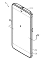
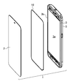
- the mobile phone 1 is made of, for example, a rectangular plate-like smartphone that is long in the vertical direction, and accommodates the display unit 2 on the front side.
- a front cabinet 3 is provided.
- a rectangular dish-shaped metal frame 3a is insert-molded, and a cover adhering recess 3b is formed continuously at the outer peripheral edge.
- the left and right widths of the cover bonding recesses 3b are narrow, and the upper and lower cover bonding recesses 3b are wide. This left and right width is narrower than that of the prior art, for example, about 0.5 to 1 mm.
- the material of the front-side cabinet 3 is not particularly limited, such as a resin molded product or a metal molded product, but it needs to be able to withstand the heat generated by the laser beam.
- the back side cabinet 4 is coupled to the back side of the front side cabinet 3, and the back side is covered with a rear cover 5.
- a circuit board and a rechargeable battery housed inside are omitted.
- the display unit 2 has a cover 2a made of a transparent glass plate.
- a touch panel (not shown) may be attached to the back side, or the cover 2a itself may be a touch panel.
- a display unit 2b such as a liquid crystal display is attached to the back side of the cover 2a.
- the cover 2a may be made of a transparent resin material that easily transmits laser light, such as an acrylic plate, but needs to be able to withstand the heat generated by the laser light.
- a black print layer is provided on the back surface of the cover 2a to hide the outside of the display area of the display unit 2b.
- the black print layer does not transmit and reflect the laser light, but absorbs it easily, and thus plays the role of the heat generating layer 11.
- the black print layer is provided by attaching an ink containing a black dye or pigment to the back surface of the cover 2a, but it must be capable of withstanding the heat generated by the laser light.
- the heat generating layer 11 may be provided by vapor deposition, film sticking, primer application, or the like.
- a thin-film reflective layer 12 that reflects part of visible light is formed on the front side of the heat generating layer 11.
- the reflective layer 12 is formed, for example, by depositing silicon oxide layers and niobium oxide layers alternately in multiple layers.
- the thickness per layer is generally 20 to 50 nm. By adjusting the thickness and the number of layers of each reflective layer 12, the reflected color changes, so that the appearance can be easily adjusted.
- the reflective layer 12 may be composed of zirconium oxide, titanium pentoxide, magnesium fluoride, tantalum pentoxide, chromium, alumina, or the like.
- the reflection layer 12 does not have a high reflectance of laser light having a wavelength of, for example, 900 nm or more and 1050 nm or less.
- silicon oxide and niobium oxide which are highly available and do not have high reflectivity of laser light, are suitable.
- a cover 2a without the reflective layer 12 is prepared as a comparative example (shown by a solid line), and a cover 2a with the reflective layer 12 is prepared as an example (shown by a broken line).
- the cover 2a is bonded by the bonding member 10 in the cover bonding recess 3b.
- the adhesive member 10 is obtained by molding a thermoplastic resin material that is melted by heating into a rectangular frame shape in front view according to the shape of the concave portion 3b for cover bonding. Although it does not specifically limit as a thermoplastic resin material, it is easy to adhere
- the cover 2a cut out from the glass plate, the adhesive member 10, the display unit 2b, the front cabinet 3 and the like molded according to the cover adhering recess 3b are prepared.
- a silicon oxide layer and a niobium oxide layer are alternately deposited in multiple layers on the back surface of the outer peripheral edge of the cover 2a that transmits laser light.
- the film thickness and the number of layers of the reflective layer are adjusted so that the reflectance of the laser beam does not increase as in the above-described embodiment.
- the heat generating layer 11 is formed on the back side of the reflective layer 12.
- an electrode of a touch panel is formed in an electrode installation process.
- this electrode installation process does not need to be.
- the adhesive member 10 is clamped between the back surface of the cover 2a and the front cabinet 3.
- the adhesive member 10 is formed in advance in a rectangular frame shape in front view according to the shape of the cover adhering recess 3b and pasted on, for example, a transparent separator with a positioning mark. Compared to the case where an adhesive member is applied to the recess 3b, it is extremely easy to provide the adhesive member 10 in the cover adhering recess 3b that is particularly narrow in the width direction.
- pressurizing step pressure is applied in a state where the adhesive member 10 is sandwiched between the back surface of the cover 2a and the inner surface of the cover adhering recess 3b. This pressurizing step is not always necessary.
- the bonding process laser light is irradiated from the front side of the cover 2a.
- the reflection layer 12 provided on the back surface of the cover 2 a has a laser beam reflectance as low as possible, most of the laser beam is transmitted through the reflection layer 12.
- the transmitted laser light is absorbed by the heat generating layer 11 and generates heat.
- the adhesive member 10 is heated and the thermoplastic resin material is melted and then cured again, and the back surface of the cover 2a is bonded to the inner surface of the cover bonding recess 3b.
- the heating condition may be, for example, 0.4 to 1.2 J, preferably 0.6 to 1.0 J at which the temperature of the adhesive member 10 is 100 to 150 ° C.
- the cover 2a When the pressurizing step is provided, the cover 2a is pressed against the front cabinet 3 side, so that the gap between the unevenness on the back surface of the cover 2a and the inner surface of the cover adhering recess 3b and the adhesive member 10 is eliminated. It is advantageous that the heat generating layer 11 can be heated by laser light to melt and cure the adhesive member 10.
- the periphery of the cover 2a is bonded to the cover adhering recess 3b formed continuously from the outer peripheral edge of the front cabinet 3 by the adhesive member 10 heated by the heat generation of the black print layer which is the heat generating layer 11 of the cover 2a.
- the conventional black printing layer which makes the inside invisible can be used as it is and the adhesive member 10 can be heated by the heat generating layer 11, it is not necessary to add a process only for providing the heat generating layer 11. .
- the waterproof mobile phone 1 can be assembled.
- the adhesive member 10 may be either a thermoplastic resin material or a thermosetting resin material, and may be liquid or solid. However, when the adhesive member 10 is shaped in advance in accordance with the adhesion site as in the above-described embodiment, it is easier to handle than the liquid and the adhesive member 10 is easily clamped, and even if the adhesion area is narrow, it is reliable. Can be glued on.
- the mobile phone 1 looks to the user in a color other than black even if the heat generating layer 11 is black, so that the appearance is improved.
- the cover 2a can be reliably bonded to the front cabinet 3 by the adhesive member 10 heated by the laser beam while enhancing the appearance with colors other than black.
- the heat generating layer 11 is a black printed layer printed on the back surface of the cover 2a. However, even if the heat generating layer 11 that easily absorbs laser light is formed on the front surface of the cover adhering recess 3b on the cover 2a side. Good.
- the heat generating layer 11 may be provided with a black print layer or a black tape, for example.
- the heat generating layer 11 is provided on the cover bonding concave portion 3b side, thereby heating the front side cabinet 3 side and softening the adhesive member 10. Can be melted or cured.
- the present invention may be configured as follows with respect to the above embodiment.
- the heat generating layer 11 is a heat generating layer provided in the black printed layer on the back surface of the cover 2a or the cover adhering recess 3b, but the heat generating layer 11 on the back surface of the cover 2a may transmit laser light to some extent.
- the adhesive member 10 may be heated by both the heat generating layer 11 provided in the cover adhering recess 3b.
- the adhesive member 10 itself may include a component that generates heat by absorbing laser light and a water material that transmits heat.
- the adhesive member 10 since the adhesive member 10 was made into the frame shape which shape
- the mobile terminal is the mobile phone 1, but has a display unit, PHS (Personal Handy-phone System), PDA (Personal Digital Assistant), smartphone, personal computer, mobile tool, electronic dictionary, calculator It may be a game machine or the like.
- PHS Personal Handy-phone System
- PDA Personal Digital Assistant
- smartphone personal computer
- mobile tool electronic dictionary
- calculator It may be a game machine or the like.
Landscapes
- Engineering & Computer Science (AREA)
- Computer Hardware Design (AREA)
- Theoretical Computer Science (AREA)
- Human Computer Interaction (AREA)
- Physics & Mathematics (AREA)
- General Engineering & Computer Science (AREA)
- General Physics & Mathematics (AREA)
- Signal Processing (AREA)
- Telephone Set Structure (AREA)
- Devices For Indicating Variable Information By Combining Individual Elements (AREA)
Abstract
携帯端末の製造方法において、カバー(2a)の正面側からレーザ光を照射し、可視光の一部を反射する反射層(12)を透過させて発熱層(11)を加熱して接着部材(10)を加熱し、カバー(2a)をカバー接着用凹部(3b)の内面に接着する。
Description
本発明は、表示ユニットと、この表示ユニットを覆うカバーと、このカバーが接着されるカバー接着用凹部が形成されたキャビネットとを有する携帯端末及びその製造方法に関するものである。
従来より、表示ユニットを覆う透明なガラスやアクリル板よりなるカバーは、表示ユニットを収容するキャビネットに両面テープなどで接着されていた。この接着部分は、タッチパネルの電極などが配置されるので、遮光性が高くて最も背面側の部材を隠すのには適している黒色印刷層により隠されることが行われている。
近年、携帯電話機に代表される携帯端末は、表示部を広くしながらも、携帯端末自体の大きさは大きくしないことが求められている。しかも、携帯端末を誤って水の中に落としてしまっても壊れない防水性能が求められている。携帯端末が一方に長い矩形板状であった場合、特にその幅方向両側は、防水性を保つために両面テープによる接着面積をある程度大きく保つ必要がある。
そこで、特許文献1のようにレーザ光を利用して熱硬化性樹脂よりなる接着部材を加熱して接着させる接着方法を利用することが考えられる。
しかしながら、外観をよくするために、従来より用いられている黒色印刷層以外の色彩が求められることがある。
一方、特許文献1のようなレーザ光を用いる方法では、黒色印刷層がレーザ光を吸収する発熱層として用いられることが多い。このため、黒色以外の発熱層とすると、レーザ光の吸収効率が悪くなる。
本発明は、かかる点に鑑みてなされたものであり、その目的とするところは、黒色以外の色彩で外観を高めながらもレーザ光により加熱された接着部材によりカバーをキャビネットに確実に接着することにある。
上記の目的を達成するために、この発明では、レーザ光を吸収する発熱層の正面側に可視光の一部を反射する反射層を設けた。
具体的には、本発明では、表示ユニットと、該表示ユニットを収容するカバー接着用凹部を有するキャビネットと、該表示ユニットの正面から該キャビネットを覆うカバーとを有する携帯端末を対象とし、
上記カバーは、レーザ光を透過する材料よりなり、該カバーの外周縁の背面には、該レーザ光の大部分を透過すると共に可視光の一部を反射する薄膜の反射層が形成され、該反射層の背面側には、上記レーザ光を吸収する発熱層が設けられ、
上記カバーの背面が上記発熱層により加熱された接着部材により上記カバー接着用凹部の内面に接着されている。
上記カバーは、レーザ光を透過する材料よりなり、該カバーの外周縁の背面には、該レーザ光の大部分を透過すると共に可視光の一部を反射する薄膜の反射層が形成され、該反射層の背面側には、上記レーザ光を吸収する発熱層が設けられ、
上記カバーの背面が上記発熱層により加熱された接着部材により上記カバー接着用凹部の内面に接着されている。
また、本発明では、表示ユニットと、該表示ユニットを収容するカバー接着用凹部を有するキャビネットと、該表示ユニットの正面から該キャビネットを覆うカバーとを有する携帯端末を製造する製造方法を対象とし、
上記製造方法は、
レーザ光を透過する上記カバーの外周縁の背面に該レーザ光の大部分を透過すると共に可視光の一部を反射する薄膜の反射層を形成する反射層形成工程と、
上記反射層の背面側に上記レーザ光を吸収する発熱層を形成する発熱層形成工程と、
上記発熱層と、上記カバー接着用凹部との間に、接着部材を挟持する挟持工程と、
上記カバーの正面側からレーザ光を照射し、上記反射層を透過させて発熱層を加熱して上記接着部材を加熱し、上記カバーを上記カバー接着用凹部の内面に接着する接着工程とを含む。
上記製造方法は、
レーザ光を透過する上記カバーの外周縁の背面に該レーザ光の大部分を透過すると共に可視光の一部を反射する薄膜の反射層を形成する反射層形成工程と、
上記反射層の背面側に上記レーザ光を吸収する発熱層を形成する発熱層形成工程と、
上記発熱層と、上記カバー接着用凹部との間に、接着部材を挟持する挟持工程と、
上記カバーの正面側からレーザ光を照射し、上記反射層を透過させて発熱層を加熱して上記接着部材を加熱し、上記カバーを上記カバー接着用凹部の内面に接着する接着工程とを含む。
このため、本発明では、反射層によって可視光の一部が反射されるので、その背面側に黒色印刷層などよりなる発熱層があっても、ユーザが見ると単なる黒色には見えず、外観が向上する。この反射層は、レーザ光の大部分を透過するので、レーザ光によって反射層の背面側の発熱層を加熱して接着部材によりカバーをカバー接着用凹部に接着することができる。このため、防水性を低下させることなく、できるだけ表示面積を広くすることができる。なお、接着部材は、熱可塑性樹脂材及び熱硬化性樹脂材のどちらでもよく、液状でも固体でもよい。反射層は、レーザ光を100%透過するのではなく、できるだけレーザ光を透過しながらも可視光の一部を透過するものが適している。
以上説明したように、本発明によれば、カバーの正面側からレーザ光を照射し、可視光の一部を反射する反射層を透過させてその背面側の発熱層を加熱して接着部材を加熱し、カバーをカバー接着用凹部の内面に接着するようにしたことにより、黒色以外の色彩で外観を高めながらもレーザ光により加熱された接着部材によりカバーをキャビネットに確実に接着することができる。
以下、本発明の実施形態を図面に基づいて説明する。
図1~図4は本発明の実施形態の携帯端末としての携帯電話機1を示し、この携帯電話機1は、例えば上下方向に長い矩形板状のスマートフォンよりなり、正面側に表示部2を収容する正面側キャビネット3を有する。正面側キャビネット3は、例えば、矩形皿状の金属フレーム3aがインサート成形され、外周縁部に一段低くなったカバー接着用凹部3bが連続して形成されている。このカバー接着用凹部3bの左右幅は狭く、上下のカバー接着用凹部3bの幅は広くなっている。この左右幅は、従来に比べてさらに狭く、例えば0.5~1mm程度となっている。正面側キャビネット3の材質は、樹脂成形品、金属成形品など特に限定されないが、レーザ光による発熱に耐えうるものである必要がある。
図1にも拡大して示すように、正面側キャビネット3の背面側には、背面側キャビネット4が結合され、その背面側がリアカバー5で覆われている。なお、図4では、内部に収容されている回路基板や充電池は省略している。
表示部2は、透明なガラス板よりなるカバー2aを有する。その背面側にタッチパネル(図示せず)が貼り付けられてもよいし、カバー2a自体がタッチパネルでもよい。カバー2aの背面側に液晶ディスプレイなどの表示ユニット2bが貼り付けられている。カバー2aは、アクリル板などの透明でレーザ光を透過しやすい樹脂材料で構成されていてもよいが、レーザ光による発熱に耐えうるものである必要がある。
本実施形態では、カバー2aの背面に表示ユニット2bの表示エリアの外側を隠す黒色印刷層が施されている。この黒色印刷層は、レーザ光を透過及び反射するのではなく、吸収しやすいので、発熱層11の役割を果たす。黒色印刷層は、黒色の染料や顔料を含むインクをカバー2aの背面に付着させることによって設けられるが、レーザ光による発熱に耐えうるものである必要がある。発熱層11を蒸着、フィルムの貼付、プライマーの塗布等によって設けてもよい。
本実施形態では、この発熱層11の正面側に可視光の一部を反射する薄膜の反射層12が形成されている。この反射層12は、例えば、酸化シリコンの層と、酸化ニオブの層とを交互に多層に蒸着したものよりなる。一層あたりの厚みは20~50nmが一般的である。各反射層12の厚さと層数を調整することにより、反射する色が変化するので、外観を調整しやすい。また、反射層12は、酸化ジルコニウム、五酸化チタン、フッ化マグネシウム、五酸化タンタル、クロム及びアルミナ系等で構成してもよい。しかしながら、本実施形態では、この反射層12が、例えば波長が900nm以上1050nm以下であるレーザ光の反射率が高くないことが重要である。この点で、入手性がよく、レーザ光の反射率が高くない酸化シリコンと酸化ニオブが適している。
例えば、図5に示すように、比較例(実線で示す)として反射層12のないカバー2aと、実施例(破線で示す)として反射層12のあるカバー2aとを用意し、可視光、赤外光等の透過率について実験した。これによると、可視光領域において、反射層12によりある所定の色が反射されて透過率が5%ほど低下している。波長が900nm以上1050nm以下であるレーザ光の反射率についても、実施例では、比較例に比べて5%程度の低下に抑えられている。
カバー2aは、カバー接着用凹部3bにおいて、接着部材10によって接着されている。接着部材10は、加熱により溶ける熱可塑性樹脂材をカバー接着用凹部3bの形状に合わせて予め正面視矩形枠状に成形したものである。熱可塑性樹脂材としては特に限定されないが、カバー2a及び正面側キャビネット3のいずれにも接着しやすく、これらの材料に悪影響を与えない温度で溶けるものである必要がある。
次に、本発明のカバー2aの貼付手順について説明する。
まず準備工程において、ガラス板から切り出したカバー2a、カバー接着用凹部3bに合わせて成形した接着部材10、表示ユニット2b、正面側キャビネット3等を用意する。
次いで、反射層形成工程において、レーザ光を透過するカバー2aの外周縁の背面に酸化シリコンの層と、酸化ニオブの層とを交互に多層に蒸着する。このとき、上述した実施例のように反射層の膜厚と層数は、レーザ光の反射率が高くならないように調整する。
次いで、黒色印刷工程において、反射層12の背面側に発熱層11を形成する。
次いで、例えば電極設置工程において、タッチパネルの電極等を形成する。なお、この電極設置工程は、なくてもよい。
次いで、挟持工程において、カバー2aの背面と、正面側キャビネット3との間に接着部材10を挟持する。接着部材10は、カバー接着用凹部3bの形状に合わせて予め正面視矩形枠状に成形し、例えば位置決めの印が付けられた透明なセパレータに貼り付けておけば、カバー2a背面又はカバー接着用凹部3bに接着部材を塗布する場合に比べ、特に幅方向の幅の狭いカバー接着用凹部3bに接着部材10を設けるのが極めて容易となる。
次いで、加圧工程において、カバー2aの背面とカバー接着用凹部3bの内面との間に接着部材10を挟持した状態で、加圧する。この加圧工程は、必ずしも必要ではない。
次いで、接着工程において、カバー2aの正面側からレーザ光を照射する。ここでは、カバー2aの背面に設けた反射層12は、できるだけレーザ光の反射率を低くされているので、レーザ光の大部分は、この反射層12を透過する。そして、この透過したレーザ光が発熱層11で吸収され、発熱する。このことで、接着部材10が加熱され、熱可塑性樹脂材が溶けた後、再び硬化し、カバー2aの背面がカバー接着用凹部3bの内面に接着される。加熱のための条件は、例えば、接着部材10の温度が100~150℃となる0.4~1.2J好ましくは、0.6~1.0Jとすればよい。なお、ここで、エネルギーJは、レーザ出力をWワット、レーザ焦点径をφmm、走査速度をVmm/secとすれば、J=W×φ/Vで計算される。なお、接着部材10の温度が150~170℃となる1.0~1.2Jのエネルギーであれば、適度に加圧した場合でも、発泡して防水性が保ちにくい。0.4Jよりも小さいと、接着部材10の発熱温度が80℃以下となり接着部材10が充分に軟化、溶融又は硬化しない。
なお、加圧工程を設けた場合、カバー2aを正面側キャビネット3側へ押さえ付けているので、カバー2a背面やカバー接着用凹部3b内面にある凹凸と接着部材10との隙間をなくした状態で、レーザ光により発熱層11を加熱して接着部材10を溶かして硬化させることができて有利である。
また、カバー2aの発熱層11である黒色印刷層の発熱によって加熱された接着部材10により、カバー2a周縁が正面側キャビネット3の外周縁部に連続して形成したカバー接着用凹部3bに接着される。そして、従来よりある、内部を見えなくする黒色印刷層をそのまま使用でき、その発熱層11によって接着部材10を加熱することができるので、発熱層11を設けるためだけの工程を追加しなくてよい。
そして、接着部材10により、カバー2aと正面側キャビネット3との間を防水可能に密閉させた状態で、回路基板、充電池等を収容して背面側キャビネット4を結合し、リアカバー5で覆うことにより、防水型の携帯電話機1を組み立てることができる。
なお、接着部材10は、熱可塑性樹脂材及び熱硬化性樹脂材のどちらでもよく、液状でも固体でもよい。しかし、上記実施形態のように接着部材10を予め接着部位に合わせた形状に成形した場合には、液体よりも取り扱いが容易で接着部材10の挟持が容易となり、接着領域が狭い場合でも、確実に接着を行うことができる。
そして、携帯電話機1は、反射層12により、可視光の一部が反射されるので、発熱層11が黒色であってもユーザには、黒色以外の色に見えるので、外観が向上する。
したがって、本実施形態では、黒色以外の色彩で外観を高めながらもレーザ光により加熱された接着部材10によりカバー2aを正面側キャビネット3に確実に接着することができる。
-変形例-
上記実施形態では、発熱層11は、カバー2aの背面に印刷した黒色印刷層としたが、カバー接着用凹部3bのカバー2a側の正面にレーザ光を吸収しやすい発熱層11を形成してもよい。この発熱層11は、例えば、黒色印刷層を施してもよいし、黒色のテープを貼り付けてもよい。
上記実施形態では、発熱層11は、カバー2aの背面に印刷した黒色印刷層としたが、カバー接着用凹部3bのカバー2a側の正面にレーザ光を吸収しやすい発熱層11を形成してもよい。この発熱層11は、例えば、黒色印刷層を施してもよいし、黒色のテープを貼り付けてもよい。
本変形例によれば、カバー2a側に発熱層11を設けられない場合でも、カバー接着用凹部3b側に発熱層11を設けることで、正面側キャビネット3側を加熱して接着部材10を軟化、溶融又は硬化させることができる。
そして、反射層12により、可視光の一部が反射されるので、カバー接着用凹部3bの発熱層11が黒色であってもユーザには、黒色以外の色に見えるので、外観が向上する。
(その他の実施形態)
本発明は、上記実施形態について、以下のような構成としてもよい。
本発明は、上記実施形態について、以下のような構成としてもよい。
すなわち、上記実施形態では、発熱層11をカバー2a背面の黒色印刷層又はカバー接着用凹部3bに設けた発熱層としているが、カバー2a背面の発熱層11がレーザ光をある程度透過するものであれば、カバー接着用凹部3bに設けた発熱層11と両方で接着部材10を加熱してもよい。さらには、接着部材10自体がレーザ光を吸収して発熱する成分及び熱を伝達した水材料を含んでいてもよい。
また、上記実施形態では、接着部材10を予め熱可塑性樹脂材を成形した枠状のものとしたので、従来の両面テープのような簡易な方法による貼付を行えるが、粘性の高い液状の接着部材10をディスペンサーなどによりカバー2aの背面又はカバー接着用凹部3bの内面に塗りつけるようにしてもよい。
また、上記実施形態では、携帯端末は、携帯電話機1としたが、表示ユニットを有する、PHS(Personal Handy-phone System )、PDA(Personal Digital Assistant)、スマートフォン、パソコン、モバイルツール、電子辞書、電卓、ゲーム機等であってもよい。
なお、以上の実施形態は、本質的に好ましい例示であって、本発明、その適用物や用途の範囲を制限することを意図するものではない。また、各実施形態に記載された技術的特徴は、互いに組合せ可能であり、組み合わせることにより、新しい技術的特徴を形成することができる。
1 携帯電話機(携帯端末)
2 表示部
2a カバー
2b 表示ユニット
3 正面側キャビネット(キャビネット)
3a 金属フレーム
3b 接着用凹部
4 背面側キャビネット
5 リアカバー
10 接着部材
11 発熱層
12 反射層
2 表示部
2a カバー
2b 表示ユニット
3 正面側キャビネット(キャビネット)
3a 金属フレーム
3b 接着用凹部
4 背面側キャビネット
5 リアカバー
10 接着部材
11 発熱層
12 反射層
Claims (4)
- 表示ユニットと、該表示ユニットを覆うカバーと、該カバーが接着されるカバー接着用凹部が形成されたキャビネットとを有する携帯端末であって、
上記カバーは、レーザ光を透過する材料よりなり、該カバーの外周縁の背面には、該レーザ光の大部分を透過すると共に可視光の一部を反射する薄膜の反射層が形成され、該反射層の背面側には、上記レーザ光を吸収する発熱層が設けられ、
上記カバーの背面が上記発熱層により加熱された接着部材により上記カバー接着用凹部の内面に接着されている
ことを特徴とする携帯端末。 - 請求項1に記載の携帯端末において、
上記反射層は、酸化シリコン、酸化ニオブ、酸化ジルコニウム、五酸化チタン、フッ化マグネシウム、五酸化タンタル、クロム及びアルミナ系からなる群から選択された少なくとも2つの層が積層されている
ことを特徴とする携帯端末。 - 表示ユニットと、該表示ユニットを覆うカバーと、該カバーが接着されるカバー接着用凹部が形成されたキャビネットとを有する携帯端末を製造する製造方法であって、
レーザ光を透過する上記カバーの外周縁の背面に該レーザ光の大部分を透過すると共に可視光の一部を反射する薄膜の反射層を形成する反射層形成工程と、
上記反射層の背面側に上記レーザ光を吸収する発熱層を形成する発熱層形成工程と、
上記発熱層と、上記カバー接着用凹部との間に、接着部材を挟持する挟持工程と、
上記カバーの正面側からレーザ光を照射し、上記反射層を透過させて発熱層を加熱して上記接着部材を加熱し、上記カバーを上記カバー接着用凹部の内面に接着する接着工程とを含む
ことを特徴とする携帯端末の製造方法。 - 請求項3に記載の携帯端末の製造方法において、
上記反射層形成工程において、酸化シリコン、酸化ニオブ、酸化ジルコニウム、五酸化チタン、フッ化マグネシウム、五酸化タンタル、クロム、アルミナ系からなる群から選択された少なくとも2つの層を積層する
ことを特徴とする携帯端末の製造方法。
Applications Claiming Priority (2)
| Application Number | Priority Date | Filing Date | Title |
|---|---|---|---|
| JP2013197066A JP6113037B2 (ja) | 2013-09-24 | 2013-09-24 | 携帯端末及びその製造方法 |
| JP2013-197066 | 2013-09-24 |
Publications (1)
| Publication Number | Publication Date |
|---|---|
| WO2015045249A1 true WO2015045249A1 (ja) | 2015-04-02 |
Family
ID=52742429
Family Applications (1)
| Application Number | Title | Priority Date | Filing Date |
|---|---|---|---|
| PCT/JP2014/004034 Ceased WO2015045249A1 (ja) | 2013-09-24 | 2014-07-31 | 携帯端末及びその製造方法 |
Country Status (3)
| Country | Link |
|---|---|
| JP (1) | JP6113037B2 (ja) |
| TW (1) | TW201518069A (ja) |
| WO (1) | WO2015045249A1 (ja) |
Cited By (1)
| Publication number | Priority date | Publication date | Assignee | Title |
|---|---|---|---|---|
| WO2018204091A1 (en) * | 2017-05-01 | 2018-11-08 | Microsoft Technology Licensing, Llc | Computing devices with an adhered cover and methods of manufacturing thereof |
Citations (7)
| Publication number | Priority date | Publication date | Assignee | Title |
|---|---|---|---|---|
| JP2001092376A (ja) * | 1999-09-20 | 2001-04-06 | Denso Corp | 表示素子およびその製造方法 |
| JP2001198982A (ja) * | 2000-01-20 | 2001-07-24 | Nissha Printing Co Ltd | 加飾プラスチック成形品の製造方法 |
| JP2009173023A (ja) * | 2007-12-25 | 2009-08-06 | Hayakawa Rubber Co Ltd | レーザー接合用シート及びそれを用いた接合方法 |
| JP2009196325A (ja) * | 2008-02-25 | 2009-09-03 | Rb Controls Co | 防水ケースの水密構造 |
| JP2011156858A (ja) * | 2010-01-08 | 2011-08-18 | Hayakawa Rubber Co Ltd | レーザー光を用いた接合方法 |
| WO2012029347A1 (ja) * | 2010-09-03 | 2012-03-08 | アルプス電気株式会社 | ガラス複合体、ガラス複合体を用いた電子機器、及び、入力装置 |
| JP2012218316A (ja) * | 2011-04-11 | 2012-11-12 | Hayakawa Rubber Co Ltd | レーザー光を用いた部材の接着方法 |
-
2013
- 2013-09-24 JP JP2013197066A patent/JP6113037B2/ja not_active Expired - Fee Related
-
2014
- 2014-07-31 WO PCT/JP2014/004034 patent/WO2015045249A1/ja not_active Ceased
- 2014-08-20 TW TW103128691A patent/TW201518069A/zh unknown
Patent Citations (7)
| Publication number | Priority date | Publication date | Assignee | Title |
|---|---|---|---|---|
| JP2001092376A (ja) * | 1999-09-20 | 2001-04-06 | Denso Corp | 表示素子およびその製造方法 |
| JP2001198982A (ja) * | 2000-01-20 | 2001-07-24 | Nissha Printing Co Ltd | 加飾プラスチック成形品の製造方法 |
| JP2009173023A (ja) * | 2007-12-25 | 2009-08-06 | Hayakawa Rubber Co Ltd | レーザー接合用シート及びそれを用いた接合方法 |
| JP2009196325A (ja) * | 2008-02-25 | 2009-09-03 | Rb Controls Co | 防水ケースの水密構造 |
| JP2011156858A (ja) * | 2010-01-08 | 2011-08-18 | Hayakawa Rubber Co Ltd | レーザー光を用いた接合方法 |
| WO2012029347A1 (ja) * | 2010-09-03 | 2012-03-08 | アルプス電気株式会社 | ガラス複合体、ガラス複合体を用いた電子機器、及び、入力装置 |
| JP2012218316A (ja) * | 2011-04-11 | 2012-11-12 | Hayakawa Rubber Co Ltd | レーザー光を用いた部材の接着方法 |
Cited By (2)
| Publication number | Priority date | Publication date | Assignee | Title |
|---|---|---|---|---|
| WO2018204091A1 (en) * | 2017-05-01 | 2018-11-08 | Microsoft Technology Licensing, Llc | Computing devices with an adhered cover and methods of manufacturing thereof |
| US10698443B2 (en) | 2017-05-01 | 2020-06-30 | Microsoft Technology Licensing, Llc | Computing devices with an adhered cover and methods of manufacturing thereof |
Also Published As
| Publication number | Publication date |
|---|---|
| TW201518069A (zh) | 2015-05-16 |
| JP2015064430A (ja) | 2015-04-09 |
| JP6113037B2 (ja) | 2017-04-12 |
Similar Documents
| Publication | Publication Date | Title |
|---|---|---|
| CN210137341U (zh) | 电子设备及其壳体组件 | |
| JP4021925B2 (ja) | 電子機器表示窓の保護パネル及び保護パネルの製造方法 | |
| US6518493B1 (en) | Display device for electronic apparatus comprising solar cell | |
| CN109581777A (zh) | 电子设备、壳体组件、电致变色模组及其制备方法 | |
| WO2015045250A1 (ja) | 携帯端末及びその製造方法 | |
| TWI534518B (zh) | Electrochromic device | |
| JP6277559B2 (ja) | 表示デバイス及びその製造方法 | |
| JP2007279756A (ja) | 表示窓に保護パネルが付された電子機器 | |
| JP2022504598A (ja) | 偏光板の製造方法 | |
| WO2015097966A1 (ja) | 携帯端末及びその製造方法 | |
| JP6113037B2 (ja) | 携帯端末及びその製造方法 | |
| WO2015097960A1 (ja) | 携帯端末及びその製造方法 | |
| JP2017090637A (ja) | 加飾部材 | |
| US9327474B2 (en) | Display device and methods for producing the same | |
| JP3225094U (ja) | 反射型液晶セル | |
| JP6245911B2 (ja) | 携帯端末及びその製造方法 | |
| JP4279890B2 (ja) | 電子機器表示窓の保護パネル及び保護パネルの製造方法 | |
| CN217821195U (zh) | 一种电致变色镜片和ar眼镜 | |
| CN214896136U (zh) | 电致变色的盖板组件及电子设备 | |
| CN105448200A (zh) | 一种增强oled户外可读性的方法 | |
| TW202445218A (zh) | 觸控顯示面板、顯示裝置、以及製造觸控顯示面板的方法 | |
| KR200364153Y1 (ko) | 페트필름에 종이 장식지가 합지된 건조가열 접착시트지 | |
| CN114895500A (zh) | 一种具有双封装空间的电致变色镜片 | |
| CN217821196U (zh) | 一种电致变色镜片 | |
| CN112925449A (zh) | 触控模组及触控显示屏 |
Legal Events
| Date | Code | Title | Description |
|---|---|---|---|
| 121 | Ep: the epo has been informed by wipo that ep was designated in this application |
Ref document number: 14849398 Country of ref document: EP Kind code of ref document: A1 |
|
| NENP | Non-entry into the national phase |
Ref country code: DE |
|
| 122 | Ep: pct application non-entry in european phase |
Ref document number: 14849398 Country of ref document: EP Kind code of ref document: A1 |