WO2015045154A1 - 照明装置、ディスプレイ装置及び制御方法 - Google Patents
照明装置、ディスプレイ装置及び制御方法 Download PDFInfo
- Publication number
- WO2015045154A1 WO2015045154A1 PCT/JP2013/076542 JP2013076542W WO2015045154A1 WO 2015045154 A1 WO2015045154 A1 WO 2015045154A1 JP 2013076542 W JP2013076542 W JP 2013076542W WO 2015045154 A1 WO2015045154 A1 WO 2015045154A1
- Authority
- WO
- WIPO (PCT)
- Prior art keywords
- light
- display
- guide plate
- light guide
- wall surface
- Prior art date
- Legal status (The legal status is an assumption and is not a legal conclusion. Google has not performed a legal analysis and makes no representation as to the accuracy of the status listed.)
- Ceased
Links
Images






Classifications
-
- G—PHYSICS
- G09—EDUCATION; CRYPTOGRAPHY; DISPLAY; ADVERTISING; SEALS
- G09G—ARRANGEMENTS OR CIRCUITS FOR CONTROL OF INDICATING DEVICES USING STATIC MEANS TO PRESENT VARIABLE INFORMATION
- G09G3/00—Control arrangements or circuits, of interest only in connection with visual indicators other than cathode-ray tubes
- G09G3/04—Control arrangements or circuits, of interest only in connection with visual indicators other than cathode-ray tubes for presentation of a single character by selection from a plurality of characters, or by composing the character by combination of individual elements, e.g. segments using a combination of such display devices for composing words, rows or the like, in a frame with fixed character positions
- G09G3/06—Control arrangements or circuits, of interest only in connection with visual indicators other than cathode-ray tubes for presentation of a single character by selection from a plurality of characters, or by composing the character by combination of individual elements, e.g. segments using a combination of such display devices for composing words, rows or the like, in a frame with fixed character positions using controlled light sources
- G09G3/12—Control arrangements or circuits, of interest only in connection with visual indicators other than cathode-ray tubes for presentation of a single character by selection from a plurality of characters, or by composing the character by combination of individual elements, e.g. segments using a combination of such display devices for composing words, rows or the like, in a frame with fixed character positions using controlled light sources using electroluminescent elements
- G09G3/14—Semiconductor devices, e.g. diodes
-
- F—MECHANICAL ENGINEERING; LIGHTING; HEATING; WEAPONS; BLASTING
- F21—LIGHTING
- F21S—NON-PORTABLE LIGHTING DEVICES; SYSTEMS THEREOF; VEHICLE LIGHTING DEVICES SPECIALLY ADAPTED FOR VEHICLE EXTERIORS
- F21S2/00—Systems of lighting devices, not provided for in main groups F21S4/00 - F21S10/00 or F21S19/00, e.g. of modular construction
-
- G—PHYSICS
- G02—OPTICS
- G02B—OPTICAL ELEMENTS, SYSTEMS OR APPARATUS
- G02B6/00—Light guides; Structural details of arrangements comprising light guides and other optical elements, e.g. couplings
- G02B6/0001—Light guides; Structural details of arrangements comprising light guides and other optical elements, e.g. couplings specially adapted for lighting devices or systems
- G02B6/0011—Light guides; Structural details of arrangements comprising light guides and other optical elements, e.g. couplings specially adapted for lighting devices or systems the light guides being planar or of plate-like form
- G02B6/0013—Means for improving the coupling-in of light from the light source into the light guide
- G02B6/0015—Means for improving the coupling-in of light from the light source into the light guide provided on the surface of the light guide or in the bulk of it
- G02B6/002—Means for improving the coupling-in of light from the light source into the light guide provided on the surface of the light guide or in the bulk of it by shaping at least a portion of the light guide, e.g. with collimating, focussing or diverging surfaces
- G02B6/0021—Means for improving the coupling-in of light from the light source into the light guide provided on the surface of the light guide or in the bulk of it by shaping at least a portion of the light guide, e.g. with collimating, focussing or diverging surfaces for housing at least a part of the light source, e.g. by forming holes or recesses
-
- G—PHYSICS
- G02—OPTICS
- G02B—OPTICAL ELEMENTS, SYSTEMS OR APPARATUS
- G02B6/00—Light guides; Structural details of arrangements comprising light guides and other optical elements, e.g. couplings
- G02B6/0001—Light guides; Structural details of arrangements comprising light guides and other optical elements, e.g. couplings specially adapted for lighting devices or systems
- G02B6/0011—Light guides; Structural details of arrangements comprising light guides and other optical elements, e.g. couplings specially adapted for lighting devices or systems the light guides being planar or of plate-like form
- G02B6/0066—Light guides; Structural details of arrangements comprising light guides and other optical elements, e.g. couplings specially adapted for lighting devices or systems the light guides being planar or of plate-like form characterised by the light source being coupled to the light guide
- G02B6/0068—Arrangements of plural sources, e.g. multi-colour light sources
-
- G—PHYSICS
- G09—EDUCATION; CRYPTOGRAPHY; DISPLAY; ADVERTISING; SEALS
- G09G—ARRANGEMENTS OR CIRCUITS FOR CONTROL OF INDICATING DEVICES USING STATIC MEANS TO PRESENT VARIABLE INFORMATION
- G09G2310/00—Command of the display device
- G09G2310/02—Addressing, scanning or driving the display screen or processing steps related thereto
- G09G2310/0232—Special driving of display border areas
-
- G—PHYSICS
- G09—EDUCATION; CRYPTOGRAPHY; DISPLAY; ADVERTISING; SEALS
- G09G—ARRANGEMENTS OR CIRCUITS FOR CONTROL OF INDICATING DEVICES USING STATIC MEANS TO PRESENT VARIABLE INFORMATION
- G09G2360/00—Aspects of the architecture of display systems
- G09G2360/16—Calculation or use of calculated indices related to luminance levels in display data
Definitions
- Embodiments described herein relate generally to a lighting device, a display device, and a method for controlling the lighting device.
- lighting device that has a large number of light sources arranged at the edge of the display and illuminates the wall surface around the display. This type of lighting device is also called an ambient lighting device.
- the brightness of the light emitted around the display is uneven.
- light of each color is not sufficiently mixed and color unevenness occurs unless a sufficient distance can be secured between the light source and an illumination target such as a wall surface.
- the conventional ambient lighting apparatus has uneven luminance and uneven color, and cannot illuminate the periphery of the display with smooth light.
- the problem to be solved by the present invention is to provide an illuminating device, a display device, and a method for controlling the illuminating device capable of illuminating the periphery of the display with uniform light.
- a lighting device includes a light guide plate and a plurality of light sources.
- the light guide plate has a hole portion whose inner wall surface functions as a light collecting surface for collecting light, guides the light collected from the inner wall surface, and radiates it from the outer peripheral edge.
- the plurality of light sources are arranged along the inner wall surface of the hole portion and irradiate the inner wall surface with light.
- the disassembled perspective view which shows schematic structure of the ambient illuminating device in one Embodiment.
- the block diagram which shows the control structure of the ambient illuminating device in one Embodiment.
- the flowchart of the process which a controller performs in one Embodiment. The figure explaining the modification of an ambient illuminating device.
- FIG. 1 is an exploded perspective view schematically showing the configuration of the ambient lighting apparatus 1.
- the ambient illumination device 1 includes a light guide plate 2, a light source unit 3, and reflection sheets 4 and 5 as reflection members.
- the light guide plate 2 has a rectangular flat plate shape including a front surface 21 and a rear surface 22 intersecting with the thickness direction, and an upper edge surface 23, a lower edge surface 24, a left edge surface 25, and a right edge surface 26 parallel to the thickness direction. Make it.
- FIG. 2 is a diagram schematically showing a II-II section of the light guide plate 2 in FIG.
- the light guide plate 2 has a light source hole 20 penetrating from the front surface 21 to the rear surface 22.
- the light source hole 20 is a perfect circle.
- the light source unit 3 includes a substrate 30 and a plurality of light sources S mounted on the substrate 30.
- the light source S includes a red LED (Light Emitting Diode) issued in red (R), a green LED emitting in green (G), and a blue LED emitting in blue (B).
- R Red
- G green
- B blue LED emitting in blue
- Each light source S is mounted on the substrate 30 such that the light emitting surface of each LED is along a perfect circle having the same diameter as the light source hole 20.
- a so-called side view type LED in which the mounting surface and the light emission direction are parallel as the LED constituting the light source S, mounting on the substrate 30 is facilitated.
- other types of light emitting elements such as LEDs of a type in which the mounting surface and the light emitting direction are perpendicular can be used by devising mounting on the substrate 30.
- the light source unit 3 is attached to the light guide plate 2 by, for example, attaching the substrate 30 to the rear surface 22 with an adhesive in a state where each light source S is inserted into the light source hole 20.
- the light emitting surfaces of the LEDs of each light source S are arranged along the inner wall surface 20a.
- each light source S is arrange
- a gap may be provided between the light emitting surface of the LED of each light source S and the inner wall surface 20a.
- the reflection sheet 4 is formed in the same shape as the front surface 21 of the light guide plate 2.
- the reflection sheet 4 is attached to the front surface 21 through, for example, a transparent adhesive.
- the reflection sheet 4 reflects light reaching the front surface 21 from the inside of the light guide plate 2 to the inside of the light guide plate 2.
- the reflection sheet 5 is formed in the same shape as the rear surface 22 of the light guide plate 2.
- the reflection sheet 5 is attached to the rear surface 22 via, for example, a transparent adhesive.
- the reflection sheet 5 reflects light reaching the rear surface 22 from the inside of the light guide plate 2 to the inside of the light guide plate 2.
- FIG. 3 is a view for explaining the light guide by the light guide plate 2.
- Light emitted from each light source S of the light source unit 3 is taken into the light guide plate 2 from the inner wall surface 20a. That is, the inner wall surface 20a functions as a lighting surface that collects light from each light source S.
- the light from each light source S propagates toward the end portion in a concentric manner as indicated by a broken-line circle while being totally reflected.
- the red, green, and blue light from one light source S is mixed before reaching the end of the light guide plate 2.
- the light from each light source S is mixed before reaching the end of the light guide plate 2.
- the ambient lighting device 1 is attached to the display 100 by pasting the back surface of the display 100 and the reflection sheet 4 via a double-sided tape 110, for example.
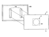
- adjustment is performed so that the display screen 101 provided on the front surface of the display 100 and the light guide plate 2 are parallel to each other.
- the light guide plate 2 and the display 100 have substantially the same size.
- the display 100 for example, various types of displays such as a placement-type television device, a wall-mounted television device, or a signage device that displays various commercial information can be used.
- a bezelless display as the display 100, the visual effect of the ambient lighting device 1 can be enhanced.
- the ambient lighting device 1 and the display 100 constitute a display device according to the present embodiment.
- FIG. 5 is a block diagram showing a configuration relating to control of the ambient lighting device 1.
- the ambient lighting device 1 includes a controller 6, a light source driver 7, and connection terminals 8 and 9.
- the connection terminal 8 connects the playback device 200 and the ambient lighting device 1 via the connection cable 300.
- the playback device 200 is a media drive that reads video data and audio data of content from an optical disc medium that conforms to a standard such as Blu-ray (registered trademark) or DVD, a hard disk drive that stores video data and audio data of content, or Both of these are provided.
- the content is, for example, a commercial video for a movie or digital signage.
- the playback device 200 reads content video data and audio data from a media drive or a hard disk drive, and outputs them to the ambient lighting device 1 via the connection cable 300 and the connection terminal 8.
- the video data and audio data output from the playback device 200 to the ambient lighting device 1 are not limited to data read from an optical disk medium or a hard disk drive.
- these data may be TV program data that is digitally broadcast or video data that is distributed via a network such as the Internet.
- connection terminal 9 connects the display 100 and the ambient lighting device 1 via the connection cable 301.
- Video data and audio data input from the playback device 200 via the connection terminal 8 are output to the display 100 via the connection terminal 9 and the connection cable 301.
- the display 100 displays an image corresponding to the input video data on the display screen 101 and outputs sound corresponding to the input audio data from a built-in or external speaker.
- connection terminals 8 and 9 are HDMI (High-Definition Multimedia Interface) terminals
- connection cables 300 and 301 are HDMI cables.
- connection terminals 8 and 9 and the connection cables 300 and 301 terminals and cables compliant with various standards can be used.
- the controller 6 is connected to the connection terminals 8 and 9 and the light source driver 7.
- the controller 6 includes a processor 60 and a memory 61.
- the processor 60 is, for example, a CPU (Central Processing Unit).
- the memory 61 is composed of, for example, a ROM (Read Only Memory) and a RAM (Random Access Memory).
- the memory 61 stores in advance a computer program to be executed by the processor 60, a lookup table (LUT) 62, and the like.
- the lookup table 62 is setting information for obtaining the lighting brightness of each light source S from the video data. Details of the lookup table 62 will be described later with reference to FIG.
- the memory 61 also functions as a work area used in the processing of the processor 60.
- the memory 61 generates drive tables (DT) 63R, 63G, 63B and the like.
- the drive table 63R is a table for writing the lighting brightness of the red LED in each light source S.
- the drive table 63G is a table for writing the lighting brightness of the green LED in each light source S.
- the drive table 63B is a table for writing the lighting brightness of the blue LED in each light source S. Details of the drive tables 63R, 63G, and 63B will be described later with reference to FIG.
- the processor 60 implements various processes related to the operation of the ambient lighting device 1 by executing a computer program. For example, the processor 60 determines the lighting brightness of each LED of each light source S based on the video data input from the playback device 200, and writes it in the drive tables 63R, 63G, and 63B. Further, the processor 60 outputs the lighting luminance written in the drive tables 63R, 63G, and 63B to the light source driver 7.
- the light source driver 7 drives each LED of each light source S according to the lighting luminance input from the processor 60.
- Each light source S is driven by, for example, PWM (Pulse Width Modulation) control.
- PWM Pulse Width Modulation
- the light source driver 7 generates a drive signal having a duty ratio corresponding to the lighting luminance, and drives each LED of each light source S.
- the controller 6 and the light source driver 7 are housed in a dedicated housing, for example, and are connected to the light source unit 3 via a cable. At least one of the controller 6 and the light source driver 7 may be accommodated in the light source hole 20.
- the ambient lighting apparatus 1 is provided with 20 light sources S1 to S20 as an example.
- the number of light sources S is not limited to this.
- the luminance for emitting the red LEDs of the light sources S1 to S20 is called lighting luminance RS1 to RS20, and the luminance for emitting the green LEDs of the light sources S1 to S20 is called lighting luminance GS1 to GS20.
- Luminances for causing the blue LEDs of the light sources S1 to S20 to emit light are referred to as lighting luminances BS1 to BS20.
- FIG. 6 is a diagram showing an outline of processing for determining the lighting luminances RS1 to RS20, GS1 to GS20, and BS1 to BS20.
- a plurality of areas A that are in contact with the end of the display screen 101 are defined.
- the ambient lighting device 1 uses the red (R) average luminance RA of the pixels included in each area A and the green (G) of the pixels included in each area A.
- Average luminance GA and the blue (B) average luminance BA of the pixels included in each region A are calculated.
- the ambient lighting device 1 determines the lighting luminances RS1 to RS20, GS1 to GS20, and BS1 to BS20 based on the obtained average luminances RA, GA, and BA of each region A.
- 20 regions A1 to A20 are defined in the same manner as the light sources S1 to S20.
- the number of areas A is not limited to this.
- Each of the areas A1 to A20 is, for example, a rectangle including the same number of pixels.
- the average luminance RA of each of the regions A1 to A20 is called RA1 to RA20
- the average luminance GA of each of the regions A1 to A20 is called GA1 to GA20
- the average luminance BA of each of the regions A1 to A20 is called BA1 to BA20.
- the average luminance RA1 to RA20, GA1 to GA20, BA1 to BA20, and the lighting luminance RS1 to RS20, GS1 to GS20, BS1 to BS20 are expressed in 256 gradations (8 bit unsigned integers).
- the above-described lookup table 62 defines the relationship between the average luminances RA1 to RA20, GA1 to GA20, BA1 to BA20, and the lighting luminances RS1 to RS20, GS1 to GS20, BS1 to BS20.
- FIG. 8 is a diagram showing an example of the data structure of the lookup table 62.
- the lookup table 62 stores coefficients for determining the lighting luminances RS1 to RS20, GS1 to GS20, and BS1 to BS20 of the light sources S1 to S20 for each of the regions A1 to A20. In the present embodiment, the coefficient is determined in the range of 0.0 to 1.0.
- the look-up table 62 determines the lighting luminances RS1 to RS20 from the average luminances RA1 to RA20, the lighting luminances GS1 to GS20 from the average luminances GA1 to GA20, and the lighting luminances BS1 to BS20 from the average luminances BA1 to BA20. Used in common.
- the coefficient stored in the lookup table 62 may be determined by evaluating in advance the degree to which lighting of the light sources S1 to S20 contributes to illumination around the areas A1 to A20.
- the drive tables 63R, 63G, and 63B described above have the same data structure.
- FIG. 9 in the areas indicated by the matrix of “A1” to “A20” and “S1” to “S20”, the lighting luminances of the light sources S1 to S20 are individually set based on the average luminances RA1 to RA20 of the regions A1 to A20. The calculated result is written.
- these lighting luminances are referred to as sub lighting luminances.
- the average luminances RA1 to RA20 of the areas A1 to A20 are written.
- the “RS” line the total value of the sub lighting luminances in the columns “S1” to “S20” is written. These total values represent the lighting luminances RS1 to RS20, respectively.
- the sub lighting brightness of the drive table 63R is obtained by multiplying the average brightness RA1 to RA20 and the coefficient stored in the lookup table 62.
- the average luminance RA1 of the area A1 is “255”.
- the coefficients of the area A10 are “0.2” for the light source S9, “0.7” for the light source S10, “0.1” for the light source S11, and “0” for the other. In this case, as shown in FIG.
- the light source S11 becomes 255 ⁇ 0.2 ⁇ “26” (rounded off after the decimal point).
- the sub-lighting luminance of the red LED for the other areas A1 to A9 and A11 to A20 of the light sources S9 to S11 is “0”. Accordingly, the lighting luminances RS9, RS10, and RS11 of the light sources S1 to S11 are “51”, “179”, and “26”, respectively.
- the controller 6 acquires one frame of video data from the video data input from the playback device 200 and stores it in the memory 61 (block B1).
- the controller 6 calculates the average red brightness RA1 to RA20 of the areas A1 to A20 in the video data stored in the block B1 (block B2).
- the controller 6 writes the calculated average luminances RA1 to RA20 in the drive table 63R.
- the controller 6 determines the lighting luminances RS1 to RS20 based on the average luminances RA1 to RA20 calculated in the block B2 (block B3). Specifically, the controller 6 calculates the sub-lighting luminances of the red LEDs of the light sources S1 to S20 for each of the regions A1 to A20 by multiplying the average luminances RA1 to RA20 by the coefficients of the lookup table 62, and drives them. Write to table 63R. Further, the controller 6 calculates the lighting luminances RS1 to RS20 by adding the sub lighting luminances written in the driving table 63R for each of the light sources S1 to S20, and writes the lighting luminances RS1 to RS20 in the driving table 63R.
- the controller 6 calculates green average luminances GA1 to GA20 in the areas A1 to A20 in the video data stored in the block B1 (block B4).
- the controller 6 writes the calculated average luminance GA1 to GA20 in the drive table 63G.
- the controller 6 determines the lighting luminances GS1 to GS20 based on the average luminances GA1 to GA20 calculated in the block B4 (block B5). Specifically, the controller 6 calculates the sub-lighting luminances of the green LEDs of the light sources S1 to S20 for each of the regions A1 to A20 by multiplying the average luminances GA1 to GA20 by the coefficients of the lookup table 62, and drives them. Write to table 63G. Further, the controller 6 calculates the lighting luminances GS1 to GS20 by summing the sub lighting luminances written in the driving table 63G for each of the light sources S1 to S20, and writes them in the driving table 63G.
- the controller 6 calculates blue average luminances BA1 to BA20 of the areas A1 to A20 in the video data stored in the block B1 (block B6).
- the controller 6 writes the calculated average luminances BA1 to BA20 in the drive table 63B.
- the controller 6 determines the lighting luminances BS1 to BS20 based on the average luminances BA1 to BA20 calculated in the block B6 (block B7). Specifically, the controller 6 calculates the sub-lighting luminance of the blue LEDs of the light sources S1 to S20 for each of the regions A1 to A20 by multiplying the average luminances BA1 to BA20 by the coefficients of the lookup table 62, and drives them. Write to table 63B. Further, the controller 6 calculates the lighting luminances BS1 to BS20 by summing the sub lighting luminances written in the driving table 63B for each of the light sources S1 to S20, and writes the lighting luminances BS1 to BS20 in the driving table 63B.
- the controller 6 drives the light sources S1 to S20 via the light source driver 7 (block B8). Specifically, the controller 6 outputs the lighting luminances RS1 to RS20, GS1 to GS20, and BS1 to BS20 written in the drive tables 63R, 63G, and 63B to the light source driver 7.
- the light source driver 7 generates a drive signal having a duty ratio corresponding to the lighting luminances RS1 to RS20, GS1 to GS20, and BS1 to BS20, and drives the LEDs of the respective colors of the light sources S1 to S20.
- the lighting that the controller 6 outputs to the light source driver 7 is performed.
- the luminances RS1 to RS20, GS1 to GS20, and BS1 to BS20 may be corrected.
- the lighting luminances RS1 to RS20, GS1 to GS20, BS1 to BS20 are normally set so that the highest luminance among the lighting luminances RS1 to RS20, GS1 to GS20, and BS1 to BS20 is “255”. Can be adopted.
- a function for performing such correction may be provided in the light source driver 7 instead of the controller 6.
- the light interlocked with the image displayed on the display screen 101 is emitted from the ambient lighting device 1 to the periphery of the display 100.
- the light from the light source S arranged in the light source hole 20 is guided by the light guide plate 2 and emitted from the outer peripheral edge of the light guide plate 2.
- light from adjacent light sources S is mixed in the light guide plate 2 and functions as a light emitting surface in which the outer peripheral edge of the light guide plate 2 is continuous. Therefore, the light emitted from the outer peripheral edge of the light guide plate 2 has a smooth and natural luminance distribution, and illuminates the surroundings with almost no color unevenness or luminance unevenness.
- the ambient lighting device 1 controls the light source S based on the video data of the video displayed on the display 100. Therefore, the ambient lighting device 1 can illuminate the surroundings in conjunction with the video.
- each light source S based on the luminance of the pixels included in the plurality of regions A as in the present embodiment, illumination linked to the luminance of each region A becomes possible.
- the lighting brightness of the LEDs of each color constituting each light source S is determined based on the average brightness of each color of the pixels included in each area A and the weighted coefficient as shown in FIG. 8 as in this embodiment.
- the light emitted from the ambient lighting device 1 to the surroundings has the same color as that of the adjacent region A. Therefore, a visual effect is provided to the viewer as if the end of the video displayed on the display 100 is expanded. Thereby, the force of the image displayed on the display 100 is increased, and the feeling of immersion in the image is further enhanced.
- the ambient lighting device 1 since the ambient lighting device 1 according to the present embodiment includes the reflection sheets 4 and 5, it is possible to increase the efficiency of light guide by the light guide plate 2.
- the ambient lighting device 1 is connected to the playback device 200 and the display 100 via connection cables 300 and 301 such as HDMI cables.
- connection cables 300 and 301 such as HDMI cables.
- the controller 6 may control each light source S based on parameters other than the average brightness of each region A. For example, the controller 6 may control each color LED of each light source S based on the average luminance of each color of the entire video displayed on the display 100.
- the controller 6 may estimate the chromaticity of the light source (illumination) when the video is shot from the video displayed on the display 100, and control each light source S based on the result.
- the controller 6 may control each light source S according to a parameter relating to ambient light such as ambient brightness of the ambient lighting device 1.
- a sensor that detects a parameter related to ambient light is provided in the ambient lighting device 1, and the controller 6 controls each light source S based on the detection result of the sensor.
- each light source S may be fixed to a specific color and brightness to emit light. In this case, by causing each light source S to emit light with an appropriate color and brightness, an effect of reducing eye strain caused by the difference between the brightness of the display screen 101 and the surrounding brightness can be obtained.
- the controller 6 may selectively switch the control method of the light source S based on the above average brightness or ambient brightness according to a user instruction or the like.
- the switching instruction may be input from the playback device 200 or the display 100 via the connection terminals 8 and 9, or may be input via an operation unit such as a button provided in the ambient lighting device 1. Also good.
- the controller 6 may perform gamma correction on the lighting luminances RS1 to RS20, GS1 to GS20, and BS1 to BS20, and control each light source S based on the corrected lighting luminance.
- the user may arbitrarily specify a gamma value used for gamma correction.
- the gamma value may be specified from the playback device 200 or the display 100 via the connection terminals 8 and 9, or specified via an operation unit such as a button provided on the ambient lighting device 1. Also good.
- the lookup table 62 that stores the coefficients related to all the light sources S and the region A. For example, if a look-up table 62 in which coefficients indicating the relationship between the continuous light sources S of 1/2 or 1/4 and the area A corresponding to these light sources S is prepared, all the light sources S are turned on. The luminance can be calculated using the coefficient stored in the lookup table 6.
- the light emitting element of the light source S is not limited to the LED, and may be a light emitting element such as an organic EL (ElectroLuminescence).
- the light source S may include light emitting elements of colors other than red, green, and blue.
- the number of light emitting elements included in the light source S is not limited to three, but may be one or two, or may be four or more.
- the control method of each light source S may be appropriately modified. For example, when the light source S includes only a single color light emitting element, the controller 6 calculates one average luminance for each region A without distinguishing red, green, and blue, and sets each light source S based on this average luminance. You may control.
- the method for attaching the ambient lighting device 1 is not limited to the method using the double-sided tape 110.
- the ambient lighting device 1 may be attached to the display 100 via a screw or the like.
- the display 100 is of a type that is hung on a wall surface via a dedicated metal fitting and a plurality of female screws for attachment to the metal fitting are provided on the back surface of the display 100, ambient lighting using the female screw and the metal fitting is used.
- the device 1 can also be attached to the display 100. Specifically, a through hole corresponding to the plurality of female screws is provided in the light guide plate 2, a male screw for fixing the display 100 and the metal fitting is passed through the through hole, and the ambient lighting device 1 is interposed.
- the display 100 is fixed to the metal fitting. If attached in this way, the ambient illumination device 1 is attached to the display 100 without providing a special structure for attaching the ambient illumination device 1 to the display 100 and without using a special tool such as the double-sided tape 110. Can do.
- the ambient lighting device 1 may be incorporated in the display 100 instead of being attached to the back surface of the display 100.
- the light source hole 20 may be covered with a black absorbing sheet that absorbs light from each light source (S).
- a black absorbing sheet that absorbs light from each light source (S).
- Such an absorbent sheet may be provided so as to cover the front surface 21 side of the light source hole 20 when the light source unit 3 is inserted and attached from the rear surface 22 side of the light guide plate 2 as shown in FIG.
- the light guide plate 2 may emit light from at least one of the front surface 21 and the rear surface 22 as well as the outer peripheral edge.
- This modification will be described with reference to the schematic diagram of FIG.
- the light guide plate 2 according to the modification has a shape larger than the shape of the display 100 viewed from the same direction when viewed from the front direction of the display screen 101.
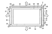
- the light guide plate 2 scatters the light guided by the light guide plate 2 to the portion 27 protruding from the display 100 when viewed from the front direction of the display screen 101 and radiates it to the front side of the display screen 101 and the opposite side thereof.
- the scattering mark is a dot pattern formed of, for example, a white pigment.
- the reflection sheets 4 and 5 are sized so as not to cover the portion 27.
- a scattering mark is provided on the rear surface 22 side of the portion 27, light scattered by the scattering mark is emitted from the front surface 21 side as indicated by an arrow D1.
- the scattering mark is provided on the front surface 21 side of the portion 27, the light scattered by the scattering mark is emitted from the rear surface 22 side as indicated by an arrow D2.
- An arrow D3 indicates light emitted from the outer peripheral edge of the light guide plate 2.
- the light guide plate 2 may have a scattering mark on only one of the front surface 21 side and the rear surface 22 side.
- the direction of the outer peripheral edge changes greatly at the four corners of the light guide plate 2, so that the light emitted from the outer peripheral edge has an unnatural luminance distribution. There is a fear. Therefore, the four corners of the light guide plate 2 may be chamfered.
- This modification will be described with reference to the schematic diagram of FIG.
- the light guide plate 2 shown in the figure has four corners rounded and chamfered with a radius R1.
- a specific value of the radius R1 may be determined as appropriate so that light emitted from the outer peripheral edge of the light guide plate 2 has a natural luminance distribution and the periphery of the display 100 is favorably illuminated.
- FIG. 12 shows an example in which the angles formed by the front surface 21 and the rear surface 22, and the upper edge surface 23, the lower edge surface 24, the left edge surface 25, and the right edge surface 26 are rounded and chamfered with a radius R2.
- the light source hole 20 is not limited to a perfect circle, and may be another shape such as an ellipse or a polygon. A modification of the shape of the light source hole 20 will be described with reference to FIG.
- the light source hole 20 shown in the figure is an ellipse having a major axis L1 and a minor axis L2.
- the major axis L1 and the minor axis L2 may be determined so that the ratio thereof is substantially the same as the aspect ratio of the display screen 101, for example.
- Each light source S is arranged in an elliptical shape along the inner wall surface 20 a of the light source hole 20.
- (Appendix 1) It has a hole portion (20) in which the inner wall surface (20a) functions as a light collecting surface for collecting light, and guides light collected from the inner wall surface (20a) to provide outer peripheral edges (23, 24, 25, 26). And a plurality of light sources (S) arranged along the inner wall surface (20a) of the hole portion (20) and irradiating the inner wall surface (20a) with light. apparatus.
- Appendix 2 The illumination device according to appendix 1, further comprising a control unit (6) that controls the plurality of light sources (S) based on video data displayed on the display (100).
- the light source (S) includes a plurality of light emitting elements that emit light of different colors, and the control unit (6) determines the luminance of the light emitting elements included in the plurality of light sources (S) based on the data.
- the lighting device according to appendix 2 wherein the light emitting element emits light with the determined luminance.
- the control unit (6) calculates an average value of luminance of pixels of the video indicated by the data for each of the plurality of regions (A) defined on the display screen (101) of the display (100).
- the illumination device according to appendix 2 wherein brightness of the plurality of light sources (S) is determined based on the average value, and the plurality of light sources (S) emit light with the determined brightness.
- the controller controls the plurality of light sources (S) based on setting information (62) defining a relationship between the average value for each of the plurality of regions (A) and the luminance of the plurality of light sources (S).
- the lighting device according to appendix 4, wherein brightness is determined and the plurality of light sources (S) emit light with the determined brightness.
- Appendix 7 The lighting device according to appendix 1, wherein the light guide plate (2) has a rectangular flat plate shape with four corners chamfered.
- the light guide plate (2) is attached to the back surface of the display (100), and the shape of the light guide plate (2) viewed from the front direction of the display screen (101) of the display (100) is viewed from the direction.
- the light guide plate (2) is larger than the shape of the display (100), and the light guide plate (2) is guided by the light guide plate (2) to a portion (27) protruding from the display (100) when viewed from the direction.
- appendix 9 The illuminating device according to appendix 1, further comprising an absorption sheet that covers the light source hole (20) and absorbs light from the plurality of light sources (S).
- the light source hole (20) has a regular circular shape or an elliptical shape in which the ratio of the major axis (L1) to the minor axis (L2) is substantially the same as the aspect ratio of the display screen (101) of the display (100).
- a display device comprising a display (100) for displaying an image and any one of the illumination devices according to attachments 1 to 11.
- (Appendix 13) It has a hole portion (20) in which the inner wall surface (20a) functions as a light collecting surface for collecting light, and guides light collected from the inner wall surface (20a) to provide outer peripheral edges (23, 24, 25, 26). And a plurality of light sources (S) arranged along the inner wall surface (20a) of the hole portion (20) and irradiating the inner wall surface (20a) with light.
- a control method for an apparatus comprising: acquiring video data displayed on a display (100); and controlling the plurality of light sources (S) based on the acquired data.
- the light source (S) includes a plurality of light emitting elements that emit light of different colors, and the controlling determines brightness of the light emitting elements respectively included in the plurality of light sources (S) based on the data.
- the controlling includes calculating an average value of luminance of pixels of the video indicated by the data for each of the plurality of areas (A) defined on the display screen (101) of the display (100).
- the control method according to appendix 13, comprising: determining the luminance of the plurality of light sources (S) based on the average value determined; and causing the plurality of light sources (S) to emit light at the determined luminance. .
- S DESCRIPTION OF SYMBOLS
- S Light source, 1 ... Ambient illumination device, 2 ... Light guide plate, 3 ... Light source part, 4, 5 ... Reflection sheet, 6 ... Controller, 7 ... Light source driver, 8, 9 ... Connection terminal, 20 ... Light source hole, 20a ... Inner wall surface, 30 ... substrate, 62 ... look-up table, 63R, 63G, 63B ... drive table, 100 ... display, 101 ... display screen, 200 ... playback device.
Landscapes
- Physics & Mathematics (AREA)
- Engineering & Computer Science (AREA)
- General Physics & Mathematics (AREA)
- General Engineering & Computer Science (AREA)
- Optics & Photonics (AREA)
- Computer Hardware Design (AREA)
- Theoretical Computer Science (AREA)
- Planar Illumination Modules (AREA)
Abstract
一実施形態に係る照明装置は、導光板と、複数の光源とを備える。上記導光板は、光を採光する採光面として内壁面が機能する孔部分を有し、上記内壁面から採光した光を導光して外周縁から放射する。上記複数の光源は、上記孔部分の内壁面に沿って配置され、上記内壁面に光を照射する。
Description
本発明の実施形態は、照明装置、ディスプレイ装置、及び照明装置の制御方法に関する。
ディスプレイの端部に配置される多数の光源を備え、ディスプレイの周囲の壁面等を照らす照明装置がある。この種の照明装置は、アンビエント照明装置とも呼ばれる。
従来のアンビエント照明装置においては、光源の配置間隔を狭めたり、光を拡散するためのレンズを光源に被せたりしなければ、ディスプレイの周囲に放たれる光の輝度にムラが生じる。また、複数色の光源を用いる場合、光源から壁面等の照明対象までの間に十分な距離が確保できなければ各色の光が十分に混ざらず、色むらが発生する。
このように、従来のアンビエント照明装置は、輝度むらや色むらを伴い、ディスプレイの周囲を滑らかな光で照明することができなかった。
本発明が解決しようとする課題は、ディスプレイの周囲をむらの無い光で照明することが可能な照明装置、ディスプレイ装置、及び、上記照明装置の制御方法を提供することである。
一実施形態に係る照明装置は、導光板と、複数の光源とを備える。上記導光板は、光を採光する採光面として内壁面が機能する孔部分を有し、上記内壁面から採光した光を導光して外周縁から放射する。上記複数の光源は、上記孔部分の内壁面に沿って配置され、上記内壁面に光を照射する。
一実施形態につき、図面を参照しながら説明する。以下の説明においては、同一の構成要素には同一の符号を付し、必要な場合を除いて重複する説明を省略する。
先ず図1~図3を用いて本実施形態に係るアンビエント照明装置1の概略的な構成を説明する。図1は、アンビエント照明装置1の構成を概略的に示す分解斜視図である。アンビエント照明装置1は、導光板2と、光源部3と、反射部材としての反射シート4,5とを備える。
導光板2は、その厚み方向と交わる前面21及び後面22と、上記厚み方向と平行な上縁面23、下縁面24、左縁面25及び右縁面26とを含む矩形の平板形状を成す。図2は、図1における導光板2のII-II断面を模式的に示す図である。導光板2は、前面21から後面22まで貫通する光源孔20を中心に有する。本実施形態において、光源孔20は正円形である。
光源部3は、基板30と、基板30に実装される複数の光源Sとを備える。光源Sは、赤色(R)で発行する赤色LED(Light Emitting Diode)と、緑色(G)で発光する緑色LEDと、青色(B)で発光する青色LEDとを備える。各光源Sは、各LEDの発光面が光源孔20と同径の正円に沿うように基板30に実装される。光源Sを構成するLEDとして、実装面と発光方向とが平行ないわゆるサイドビュータイプのLEDを用いることで、基板30への実装が容易となる。但し、実装面と発光方向とが垂直を成すタイプのLEDなど他種の発光素子であっても、基板30への実装を工夫することで利用可能である。
光源部3は、各光源Sを光源孔20に挿入した状態で、例えば基板30を後面22に接着剤を介して貼着することによって導光板2に取り付けられる。このように光源Sを取り付けると、各光源SのLEDの発光面が内壁面20aに沿って並ぶ状態となる。本実施形態では、LEDの発光面が光源孔20と同径の正円に沿うように各光源Sを配置しているため、各光源SのLEDの発光面は内壁面20aに接触する。各光源SのLEDの発光面と内壁面20aとの間に隙間を設けてもよい。
反射シート4は、導光板2の前面21と同形状に形成される。反射シート4は、例えば透明な接着材を介して前面21に貼着される。反射シート4は、導光板2の内部から前面21に到達する光を、導光板2の内部に反射する。
反射シート5は、導光板2の後面22と同形状に形成される。反射シート5は、例えば透明な接着材を介して後面22に貼着される。反射シート5は、導光板2の内部から後面22に到達する光を、導光板2の内部に反射する。
図3は、導光板2による導光を説明するための図である。光源部3の各光源Sから出射した光は、内壁面20aから導光板2の内部に取り込まれる。すなわち、内壁面20aは、各光源Sからの光を採光する採光面として機能する。導光板2の内部において各光源Sからの光は、破線円にて示すように同心円状に、全反射しながら端部に向けて伝搬する。1つの光源Sからの赤色、緑色及び青色の光は、導光板2の端部に到達するまでに混色される。また、近接して配置された複数の光源Sが発光する場合には、各光源Sからの光が導光板2の端部に到達するまでに混色される。導光板2の端部に到達した光は、図3中に矢印で示すように、導光板2の外周縁、すなわち上縁面23、下縁面24、左縁面25及び右縁面26から外部に向けて出射する。
図4を用いてアンビエント照明装置1の取り付け方法の一例を説明する。アンビエント照明装置1は、例えば両面テープ110を介してディスプレイ100の背面と反射シート4とを貼り付けることで、ディスプレイ100に取り付けられる。この取り付けに際しては、ディスプレイ100の前面に設けられた表示画面101と導光板2とが平行となるように調整する。表示画面101の正面方向から見たときに、導光板2とディスプレイ100とは、略同一のサイズとなる。ディスプレイ100としては、例えば載置タイプのテレビ装置、壁掛けタイプのテレビ装置、或いは各種のコマーシャル情報を表示するサイネージ装置等、様々な種類のディスプレイを用いることができる。ディスプレイ100として、ベゼルレスのディスプレイを用いることで、アンビエント照明装置1による視覚効果を高めることができる。
アンビエント照明装置1及びディスプレイ100は、本実施形態に係るディスプレイ装置を構成する。
続いて、アンビエント照明装置1の制御に関わる構成について説明する。
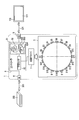
図5は、アンビエント照明装置1の制御に関わる構成を示すブロック図である。アンビエント照明装置1は、コントローラ6と、光源ドライバ7と、接続端子8,9とを備える。
図5は、アンビエント照明装置1の制御に関わる構成を示すブロック図である。アンビエント照明装置1は、コントローラ6と、光源ドライバ7と、接続端子8,9とを備える。
接続端子8は、再生装置200と、アンビエント照明装置1とを接続ケーブル300を介して接続する。再生装置200は、例えばBlu-ray(登録商標)或いはDVD等の規格に準拠した光ディスクメディアからコンテンツの映像データ及び音声データを読み取るメディアドライブ、コンテンツの映像データ及び音声データを記憶するハードディスクドライブ、或いはこれらの双方を備える。上記コンテンツは、例えば映画やデジタルサイネージ用のコマーシャル映像である。
再生装置200は、メディアドライブ或いはハードディスクドライブからコンテンツの映像データ及び音声データを読み取り、接続ケーブル300及び接続端子8を介してアンビエント照明装置1に出力する。再生装置200からアンビエント照明装置1に出力される映像データ及び音声データは、光ディスクメディアやハードディスクドライブから読み取られるデータに限られない。その他に、これらのデータは、ディジタル放送されるテレビ番組のデータやインターネット等のネットワークを介して配信される映像のデータであってもよい。
接続端子9は、ディスプレイ100とアンビエント照明装置1とを、接続ケーブル301を介して接続する。接続端子8を介して再生装置200から入力される映像データ及び音声データは、接続端子9及び接続ケーブル301を介してディスプレイ100に出力される。ディスプレイ100は、入力される映像データに応じた画像を表示画面101に表示するとともに、入力される音声データに応じた音声を内蔵或いは外付けのスピーカから出力する。
例えば、接続端子8,9はHDMI(High-Definition Multimedia Interface)端子であり、接続ケーブル300,301はHDMIケーブルである。この他にも、接続端子8,9及び接続ケーブル300,301としては、様々な規格に準拠した端子及びケーブルを用いることができる。
コントローラ6は、接続端子8,9及び光源ドライバ7に接続される。コントローラ6は、プロセッサ60と、メモリ61とを備える。プロセッサ60は、例えばCPU(Central Processing Unit)である。
メモリ61は、例えばROM(Read Only Memory)及びRAM(Random Access Memory)にて構成される。メモリ61は、プロセッサ60に実行させるためのコンピュータプログラム及びルックアップテーブル(LUT)62等を予め記憶する。ルックアップテーブル62は、映像データから各光源Sの点灯輝度を求めるための設定情報である。ルックアップテーブル62の詳細については、図8の説明にて後述する。
メモリ61は、プロセッサ60の処理にて使用されるワークエリアとしても機能する。この場合において、メモリ61は、駆動テーブル(DT)63R,63G,63B等を生成する。駆動テーブル63Rは、各光源Sにおける赤色LEDの点灯輝度を書き込むためのテーブルである。駆動テーブル63Gは、各光源Sにおける緑色LEDの点灯輝度を書き込むためのテーブルである。駆動テーブル63Bは、各光源Sにおける青色LEDの点灯輝度を書き込むためのテーブルである。駆動テーブル63R,63G,63Bの詳細については、図9の説明にて後述する。
プロセッサ60は、コンピュータプログラムを実行することでアンビエント照明装置1の動作に関わる各種の処理を実現する。例えばプロセッサ60は、再生装置200から入力される映像データに基づいて各光源Sの各LEDの点灯輝度を決定し、駆動テーブル63R,63G,63Bに書き込む。さらにプロセッサ60は、駆動テーブル63R,63G,63Bに書き込んだ点灯輝度を光源ドライバ7に出力する。
光源ドライバ7は、プロセッサ60から入力される点灯輝度に応じて、各光源Sの各LEDを駆動する。各光源Sの駆動は、例えばPWM(Pulse Width Modulation)制御にて行う。この場合において、光源ドライバ7は、点灯輝度に応じたデューティ比の駆動信号を生成し、各光源Sの各LEDを駆動する。
コントローラ6及び光源ドライバ7は、例えば専用の筐体に収納され、ケーブルを介して光源部3に接続される。コントローラ6及び光源ドライバ7の少なくとも一方が光源孔20に収納されてもよい。
各光源Sを制御するための具体的な処理について説明する。
本実施形態においては、図5に示すようにアンビエント照明装置1が20個の光源S1~S20を備える場合を例にとる。但し、光源Sの数はこれに限られるものではない。
本実施形態においては、図5に示すようにアンビエント照明装置1が20個の光源S1~S20を備える場合を例にとる。但し、光源Sの数はこれに限られるものではない。
以下の説明においては、光源S1~S20の赤色LEDを発光させるための輝度を点灯輝度RS1~RS20と呼び、光源S1~S20の緑色LEDを発光させるための輝度を点灯輝度GS1~GS20と呼び、光源S1~S20の青色LEDを発光させるための輝度を点灯輝度BS1~BS20と呼ぶ。
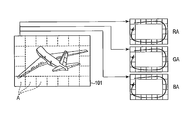
図6は、点灯輝度RS1~RS20,GS1~GS20,BS1~BS20を決定する処理の概要を示す図である。本実施形態においては、表示画面101の端部に接する複数の領域Aを定義する。アンビエント照明装置1は、表示画面101に表示される映像の映像データに基づいて、各領域Aに含まれる画素の赤色(R)の平均輝度RAと、各領域Aに含まれる画素の緑色(G)の平均輝度GAと、各領域Aに含まれる画素の青色(B)の平均輝度BAとを演算する。アンビエント照明装置1は、求めた各領域Aの平均輝度RA,GA,BAに基づいて、点灯輝度RS1~RS20,GS1~GS20,BS1~BS20を決定する。
図7に示すように、本実施形態においては光源S1~S20と同じく、20個の領域A1~A20を定義する。但し、領域Aの数はこれに限られるものではない。
領域A1~A20は、例えばいずれも同数の画素を含む矩形である。以下、領域A1~A20それぞれの平均輝度RAをRA1~RA20と呼び、領域A1~A20それぞれの平均輝度GAをGA1~GA20と呼び、領域A1~A20それぞれの平均輝度BAをBA1~BA20と呼ぶ。
例えば平均輝度RA1~RA20,GA1~GA20,BA1~BA20及び点灯輝度RS1~RS20,GS1~GS20,BS1~BS20は、256階調(8 bit unsigned integers)にて表現する。
上述のルックアップテーブル62は、平均輝度RA1~RA20,GA1~GA20,BA1~BA20と、点灯輝度RS1~RS20,GS1~GS20,BS1~BS20との関係を定める。
図8は、ルックアップテーブル62のデータ構造例を示す図である。ルックアップテーブル62は、領域A1~A20のそれぞれについて、光源S1~S20の点灯輝度RS1~RS20,GS1~GS20,BS1~BS20を定めるための係数を格納する。本実施形態においては、係数を0.0以上1.0以下の範囲で定める。ルックアップテーブル62は、平均輝度RA1~RA20から点灯輝度RS1~RS20を求める際、平均輝度GA1~GA20から点灯輝度GS1~GS20を求める際、平均輝度BA1~BA20から点灯輝度BS1~BS20を求める際に共通して使用される。ルックアップテーブル62に格納する係数は、領域A1~A20の周囲の照明に際して光源S1~S20の点灯が寄与する程度を予め評価することにより定めればよい。
上述の駆動テーブル63R,63G,63Bは、いずれも同様のデータ構造を有する。駆動テーブル63R,63G,63Bを代表して、駆動テーブル63Rのデータ構造例を図9に示す。図9において、「A1」~「A20」と「S1」~「S20」のマトリクスで示される領域には、領域A1~A20の平均輝度RA1~RA20に基づき光源S1~S20の点灯輝度を個別に演算した結果が書き込まれる。以下、これらの点灯輝度をサブ点灯輝度と呼ぶ。「RA」のカラムには、領域A1~A20の平均輝度RA1~RA20が書き込まれる。「RS」のラインには、「S1」~「S20」のカラムにおけるサブ点灯輝度の合計値が書き込まれる。これらの合計値が、それぞれ点灯輝度RS1~RS20を表す。
本実施形態において、駆動テーブル63Rのサブ点灯輝度は、平均輝度RA1~RA20とルックアップテーブル62に格納された係数とを掛け合わせることで求められる。例えば図9においては、領域A1の平均輝度RA1が「255」である。図8のルックアップテーブル62において、領域A10の係数は、光源S9が「0.2」、光源S10が「0.7」、光源S11が「0.1」、その他が「0」である。この場合、図9に示すように、領域A10に関する赤色LEDのサブ点灯輝度は、光源S9が255×0.2=「51」、光源S10が255×0.7≒「179」(小数点以下四捨五入)、光源S11が255×0.2≒「26」(小数点以下四捨五入)となる。光源S9~S11の他の領域A1~A9,A11~A20に関する赤色LEDのサブ点灯輝度は「0」である。したがって、光源S1~S11の点灯輝度RS9,RS10,RS11は、それぞれ「51」、「179」、「26」となる。
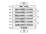
図10のフローチャートを参照して、光源S1~S20を制御するにあたりコントローラ6が実行する処理の流れを説明する。ディスプレイ100に映像を表示させる際、再生装置200から順次出力される映像データ及び音声データは、アンビエント照明装置1を通過(パススルー)してディスプレイ100に入力される。ディスプレイ100は、入力される映像データに応じた映像を表示画面101に表示するとともに、入力される音声データに応じた音声を上記スピーカから出力する。このようにしてコンテンツが再生されている間、コントローラ6は、例えば所定の時間周期で当該フローチャートに示す処理を繰り返し実行する。
先ずコントローラ6は、再生装置200から入力される映像データから1フレームの映像データを取得し、メモリ61に保存する(ブロックB1)。
続いて、コントローラ6は、ブロックB1にて保存した映像データにおける領域A1~A20の赤色の平均輝度RA1~RA20を算出する(ブロックB2)。コントローラ6は、算出した平均輝度RA1~RA20を駆動テーブル63Rに書き込む。
コントローラ6は、ブロックB2にて算出した平均輝度RA1~RA20に基づき、点灯輝度RS1~RS20を決定する(ブロックB3)。具体的には、コントローラ6は、平均輝度RA1~RA20にルックアップテーブル62の各係数を乗じることで、領域A1~A20のそれぞれについて光源S1~S20の赤色LEDのサブ点灯輝度を算出し、駆動テーブル63Rに書き込む。さらに、コントローラ6は、駆動テーブル63Rに書き込んだサブ点灯輝度を光源S1~S20ごとに合計することで点灯輝度RS1~RS20を算出し、駆動テーブル63Rに書き込む。
続いて、コントローラ6は、ブロックB1にて保存した映像データにおける領域A1~A20の緑色の平均輝度GA1~GA20を算出する(ブロックB4)。コントローラ6は、算出した平均輝度GA1~GA20を駆動テーブル63Gに書き込む。
コントローラ6は、ブロックB4にて算出した平均輝度GA1~GA20に基づき、点灯輝度GS1~GS20を決定する(ブロックB5)。具体的には、コントローラ6は、平均輝度GA1~GA20にルックアップテーブル62の各係数を乗じることで、領域A1~A20のそれぞれについて光源S1~S20の緑色LEDのサブ点灯輝度を算出し、駆動テーブル63Gに書き込む。さらに、コントローラ6は、駆動テーブル63Gに書き込んだサブ点灯輝度を光源S1~S20ごとに合計することで点灯輝度GS1~GS20を算出し、駆動テーブル63Gに書き込む。
続いて、コントローラ6は、ブロックB1にて保存した映像データにおける領域A1~A20の青色の平均輝度BA1~BA20を算出する(ブロックB6)。コントローラ6は、算出した平均輝度BA1~BA20を駆動テーブル63Bに書き込む。
コントローラ6は、ブロックB6にて算出した平均輝度BA1~BA20に基づき、点灯輝度BS1~BS20を決定する(ブロックB7)。具体的には、コントローラ6は、平均輝度BA1~BA20にルックアップテーブル62の各係数を乗じることで、領域A1~A20のそれぞれについて光源S1~S20の青色LEDのサブ点灯輝度を算出し、駆動テーブル63Bに書き込む。さらに、コントローラ6は、駆動テーブル63Bに書き込んだサブ点灯輝度を光源S1~S20ごとに合計することで点灯輝度BS1~BS20を算出し、駆動テーブル63Bに書き込む。
ブロックB7の後、コントローラ6は、光源ドライバ7を介して光源S1~S20を駆動する(ブロックB8)。具体的には、コントローラ6は、駆動テーブル63R,63G,63Bに書き込んだ点灯輝度RS1~RS20,GS1~GS20,BS1~BS20を光源ドライバ7に出力する。光源ドライバ7は、点灯輝度RS1~RS20,GS1~GS20,BS1~BS20に応じたデューティ比の駆動信号を生成し、光源S1~S20の各色のLEDを駆動する。
なお、駆動テーブル63R,63G,63Bに書き込まれる点灯輝度RS1~RS20,GS1~GS20,BS1~BS20のいずれかが最大輝度である「255」を超える場合、コントローラ6が光源ドライバ7に出力する点灯輝度RS1~RS20,GS1~GS20,BS1~BS20を補正してもよい。例えば、上記補正としては、点灯輝度RS1~RS20,GS1~GS20,BS1~BS20のうちの最も高い輝度が「255」となるように、点灯輝度RS1~RS20,GS1~GS20,BS1~BS20を正規化する処理を採用できる。このような補正を行う機能を、コントローラ6ではなく光源ドライバ7に持たせてもよい。
図10のフローチャートに示す処理が繰り返し実行されることで、表示画面101に表示される映像と連動した光がアンビエント照明装置1からディスプレイ100の周囲に放射される。
以上説明した本実施形態に係るアンビエント照明装置1においては、光源孔20内に配置された光源Sからの光を導光板2により導き、導光板2の外周縁から放射させる。このような構成においては、隣接する光源Sからの光は導光板2内で混ざり合い、導光板2の外周縁が連続した発光面のように機能する。そのため、導光板2の外周縁から放射される光は滑らかで自然な輝度分布を持ち、色むらや輝度むらを殆ど生じることなく周囲を照らす。
また、本実施形態に係るアンビエント照明装置1は、ディスプレイ100に表示される映像の映像データに基づいて光源Sを制御する。そのため、アンビエント照明装置1は、映像と連動して周囲を照明することができる。本実施形態のように複数の領域Aに含まれる画素の輝度に基づいて各光源Sを制御することで、各領域Aの輝度と連動した照明が可能となる。さらに、本実施形態のように各領域Aに含まれる画素の各色の平均輝度と、図8に示すように重み付けした係数とに基づいて各光源Sを構成する各色のLEDの点灯輝度を決定すると、アンビエント照明装置1から周囲に放射される光は、隣接する領域Aと同様の色合いとなる。そのため、ディスプレイ100に表示される映像の端部があたかも拡張したような視覚効果を視聴者に与える。これにより、ディスプレイ100に表示される映像の迫力が増し、映像への没入感がさらに高まる。
また、本実施形態に係るアンビエント照明装置1は、反射シート4,5を備えるため、導光板2による光の導光の効率を高めることができる。
また、本実施形態に係るアンビエント照明装置1は、HDMIケーブル等の接続ケーブル300,301を介して再生装置200及びディスプレイ100に接続される。このような簡単な接続形態を採用することにより、アンビエント照明装置1を様々なタイプのディスプレイ100に接続することが可能となる。
(変形例)
いくつかの変形例を説明する。
コントローラ6は、各領域Aの平均輝度以外のパラメータに基づいて各光源Sを制御してもよい。例えば、コントローラ6は、ディスプレイ100に表示される映像全体の各色の平均輝度に基づいて各光源Sの各色のLEDを制御してもよい。
いくつかの変形例を説明する。
コントローラ6は、各領域Aの平均輝度以外のパラメータに基づいて各光源Sを制御してもよい。例えば、コントローラ6は、ディスプレイ100に表示される映像全体の各色の平均輝度に基づいて各光源Sの各色のLEDを制御してもよい。
また、コントローラ6は、ディスプレイ100に表示される映像から、その映像を撮影したときの光源(照明)の色度を推定し、その結果に基づいて各光源Sを制御してもよい。
また、コントローラ6は、アンビエント照明装置1の周囲の明るさなどの環境光に関するパラメータに応じて各光源Sを制御してもよい。この場合には、例えば環境光に関するパラメータを検知するセンサをアンビエント照明装置1に設け、コントローラ6が当該センサの検知結果に基づいて各光源Sを制御する。また、各光源Sを特定の色及び輝度に固定して発光させてもよい。この場合にあっては、適切な色及び輝度にて各光源Sを発光させることにより、表示画面101の明るさと周囲の明るさとの違いに起因した眼精疲労を軽減する効果等が得られる。
コントローラ6は、上記した平均輝度や周囲の明るさなどに基づく光源Sの制御方法を、ユーザの指示などに応じて選択的に切り替えて実行してもよい。この場合において、切り替えの指示は、例えば再生装置200或いはディスプレイ100から接続端子8,9を介して入力されてもよいし、アンビエント照明装置1に設けたボタン等の操作ユニットを介して入力されてもよい。
コントローラ6は、点灯輝度RS1~RS20,GS1~GS20,BS1~BS20にガンマ補正を施し、当該補正後の点灯輝度に基づいて各光源Sを制御してもよい。また、ガンマ補正に用いるガンマの値をユーザが任意に指定できるようにしてもよい。この場合において、ガンマの値は、例えば再生装置200或いはディスプレイ100から接続端子8,9を介して指定されてもよいし、アンビエント照明装置1に設けたボタン等の操作ユニットを介して指定されてもよい。
図7に示すように光源Sと領域Aとが上下及び左右において対称の関係にある場合には、全ての光源S及び領域Aに関する係数を格納したルックアップテーブル62を用意する必要はない。例えば連続する1/2或いは1/4の数の光源Sと、これら光源Sに対応する領域Aとの関係を示す係数が格納されたルックアップテーブル62を用意すれば、全ての光源Sの点灯輝度を当該ルックアップテーブル6に格納された係数にて算出することができる。
光源Sの発光素子はLEDに限定されず、例えば有機EL(ElectroLuminescence)等の発光素子でもよい。また、光源Sは、赤色、緑色及び青色以外の色の発光素子を備えてもよい。光源Sが備える発光素子の数は3つに限定されず、1つ或いは2つのみであってもよいし、4つ以上であってもよい。光源Sが備える発光素子の数を変更する場合、各光源Sの制御の手法を適宜修正すればよい。例えば光源Sが単色の発光素子のみを備える場合において、コントローラ6は、各領域Aに関して赤色、緑色及び青色を区別することなく1つの平均輝度を算出し、この平均輝度に基づいて各光源Sを制御してもよい。
アンビエント照明装置1の取り付け方法は、両面テープ110を用いる方法に限定されない。アンビエント照明装置1は、ねじ等を介してディスプレイ100に取り付けられてもよい。ディスプレイ100が専用の金具を介して壁面に掛けるタイプであり、ディスプレイ100の背面に上記金具への取り付け用の複数の雌ねじが設けられている場合には、当該雌ねじ及び金具を利用してアンビエント照明装置1をディスプレイ100に取り付けることもできる。具体的には、導光板2に当該複数の雌ねじに対応する貫通孔を設け、ディスプレイ100と上記金具とを固定するための雄ねじを上記貫通孔にも通し、アンビエント照明装置1を介在させた状態でディスプレイ100を上記金具に固定する。このように取り付ければ、アンビエント照明装置1を取り付けるための特別な構造をディスプレイ100に設けることなく、また、両面テープ110等の特別な道具を用いることなく、アンビエント照明装置1をディスプレイ100に取り付けることができる。
アンビエント照明装置1は、ディスプレイ100の背面に取り付けられるのではなく、ディスプレイ100に組み込まれてもよい。
各光源(S)からの光を吸収する黒色の吸収シートで光源孔20を覆ってもよい。このような吸収シートは、例えば図2に示すように光源部3を導光板2の後面22側から挿入して取り付ける場合には、光源孔20の前面21側を覆うように設ければよい。
導光板2は、外周縁だけでなく、前面21及び後面22の少なくとも一方から光を出射してもよい。この変形例につき、図11の模式図を用いて説明する。同図に示すように、当該変形例に係る導光板2は、表示画面101の正面方向から見た際に、同方向から見たディスプレイ100の形状よりも大きい形状を有する。導光板2は、表示画面101の正面方向から見た際にディスプレイ100からはみ出す部分27に、導光板2にて導光される光を散乱して表示画面101の正面側及びその反対側に放射する散乱マークを有する。散乱マークは、例えば白色の顔料で形成されるドットパターンである。当該変形例において、反射シート4,5は、上記部分27を覆わない大きさとする。上記部分27の後面22側に散乱マークを設けた場合、矢印D1で示すように当該散乱マークで散乱した光が前面21側から出射する。上記部分27の前面21側に散乱マークを設けた場合、矢印D2で示すように当該散乱マークで散乱した光が後面22側から出射する。矢印D3は、導光板2の外周縁から放射される光を示す。導光板2は、前面21側及び後面22側のいずれか一方にのみ散乱マークを有してもよい。
上記実施形態のように導光板2を矩形の平板形状とする場合、導光板2の4隅で外周縁の方向が大きく変化するため、外周縁から放射される光が不自然な輝度分布となる虞がある。そこで、導光板2の4隅を面取りしてもよい。この変形例につき、図12の模式図を用いて説明する。同図に示す導光板2は、4隅が半径R1で丸み面取りされている。半径R1の具体的な値は、導光板2の外周縁から放射される光が自然な輝度分布となり、かつディスプレイ100の周囲が好適に照明されるように、適宜に定めればよい。また、前面21及び後面22と、上縁面23、下縁面24、左縁面25及び右縁面26とがなす角を面取りしてもよい。図12においては、前面21及び後面22と、上縁面23、下縁面24、左縁面25及び右縁面26とがなす角を、それぞれ半径R2で丸み面取りした例を示している。このように面取りすれば、導光板2の後方にある壁面を、外周縁の直ぐ後ろから照明することができる。また、外周縁から放射される光をユーザに直接視認させることもできる。
光源孔20は、正円形に限定されず、例えば楕円形や多角形といった他の形状であってもよい。光源孔20の形状に関する一変形例につき、図13を用いて説明する。同図に示す光源孔20は、長軸がL1で短軸がL2の楕円形である。長軸L1及び短軸L2は、例えばそれらの比が表示画面101のアスペクト比と実質的に同一となるように定めてもよい。各光源Sは、光源孔20の内壁面20aに沿って楕円形に配置される。
本発明のいくつかの実施形態を説明したが、これらの実施形態は、例として提示したものであり、発明の範囲を限定することは意図していない。これら新規な実施形態は、その他の様々な形態で実施されることが可能であり、発明の要旨を逸脱しない範囲で、種々の省略、置き換え、変更を行うことができる。これら実施形態やその変形は、発明の範囲や要旨に含まれるとともに、特許請求の範囲に記載された発明とその均等の範囲に含まれる。
以上説明した実施形態及び変形例においては、例えば以下の付記で示す技術的思想が開示されている。
(付記1)
光を採光する採光面として内壁面(20a)が機能する孔部分(20)を有し、前記内壁面(20a)から採光した光を導光して外周縁(23,24,25,26)から放射する導光板(2)と、前記孔部分(20)の内壁面(20a)に沿って配置され、前記内壁面(20a)に光を照射する複数の光源(S)と、を備える照明装置。
光を採光する採光面として内壁面(20a)が機能する孔部分(20)を有し、前記内壁面(20a)から採光した光を導光して外周縁(23,24,25,26)から放射する導光板(2)と、前記孔部分(20)の内壁面(20a)に沿って配置され、前記内壁面(20a)に光を照射する複数の光源(S)と、を備える照明装置。
(付記2)
ディスプレイ(100)に表示される映像のデータに基づき前記複数の光源(S)を制御する制御部(6)をさらに備える、付記1に記載の照明装置。
ディスプレイ(100)に表示される映像のデータに基づき前記複数の光源(S)を制御する制御部(6)をさらに備える、付記1に記載の照明装置。
(付記3)
前記光源(S)は、異なる色で発光する複数の発光素子を備え、前記制御部(6)は、前記複数の光源(S)がそれぞれ備える前記発光素子の輝度を前記データに基づいて決定し、決定した輝度で前記発光素子を発光させる、付記2に記載の照明装置。
前記光源(S)は、異なる色で発光する複数の発光素子を備え、前記制御部(6)は、前記複数の光源(S)がそれぞれ備える前記発光素子の輝度を前記データに基づいて決定し、決定した輝度で前記発光素子を発光させる、付記2に記載の照明装置。
(付記4)
前記制御部(6)は、前記ディスプレイ(100)の表示画面(101)に定められた複数の領域(A)のそれぞれについて、前記データが示す映像の画素の輝度の平均値を算出し、算出した平均値に基づいて前記複数の光源(S)の輝度を決定し、決定した輝度で前記複数の光源(S)を発光させる、付記2に記載の照明装置。
前記制御部(6)は、前記ディスプレイ(100)の表示画面(101)に定められた複数の領域(A)のそれぞれについて、前記データが示す映像の画素の輝度の平均値を算出し、算出した平均値に基づいて前記複数の光源(S)の輝度を決定し、決定した輝度で前記複数の光源(S)を発光させる、付記2に記載の照明装置。
(付記5)
前記制御部は、前記複数の領域(A)それぞれについての前記平均値と前記複数の光源(S)の輝度との関係を定めた設定情報(62)に基づいて前記複数の光源(S)の輝度を決定し、決定した輝度で前記複数の光源(S)を発光させる、付記4に記載の照明装置。
前記制御部は、前記複数の領域(A)それぞれについての前記平均値と前記複数の光源(S)の輝度との関係を定めた設定情報(62)に基づいて前記複数の光源(S)の輝度を決定し、決定した輝度で前記複数の光源(S)を発光させる、付記4に記載の照明装置。
(付記6)
前記導光板(2)の厚み方向と交わる少なくとも一方の面に設けられ、前記導光板(2)の内部から外部に向かう光を前記導光板(2)の内部に反射する反射部材(4,5)をさらに備える、付記1に記載の照明装置。
前記導光板(2)の厚み方向と交わる少なくとも一方の面に設けられ、前記導光板(2)の内部から外部に向かう光を前記導光板(2)の内部に反射する反射部材(4,5)をさらに備える、付記1に記載の照明装置。
(付記7)
前記導光板(2)は、4隅が面取りされた矩形の平板形状を有する、付記1に記載の照明装置。
前記導光板(2)は、4隅が面取りされた矩形の平板形状を有する、付記1に記載の照明装置。
(付記8)
前記導光板(2)は、ディスプレイ(100)の背面に取り付けられ、前記ディスプレイ(100)の表示画面(101)の正面方向から見た前記導光板(2)の形状が、前記方向から見た前記ディスプレイ(100)の形状よりも大きく、前記導光板(2)は、前記方向から見た際に前記ディスプレイ(100)からはみ出す部分(27)に、前記導光板(2)にて導光される光を散乱して前記表示画面(101)の正面側及びその反対側の少なくとも一方に放射する散乱マークを有する、付記1に記載の照明装置。
前記導光板(2)は、ディスプレイ(100)の背面に取り付けられ、前記ディスプレイ(100)の表示画面(101)の正面方向から見た前記導光板(2)の形状が、前記方向から見た前記ディスプレイ(100)の形状よりも大きく、前記導光板(2)は、前記方向から見た際に前記ディスプレイ(100)からはみ出す部分(27)に、前記導光板(2)にて導光される光を散乱して前記表示画面(101)の正面側及びその反対側の少なくとも一方に放射する散乱マークを有する、付記1に記載の照明装置。
(付記9)
前記光源孔(20)を覆い、前記複数の光源(S)からの光を吸収する吸収シートをさらに備える、付記1に記載の照明装置。
前記光源孔(20)を覆い、前記複数の光源(S)からの光を吸収する吸収シートをさらに備える、付記1に記載の照明装置。
(付記10)
前記導光板(2)は、厚み方向と交わるいずれか一方の面(21,22)と、前記外周縁(23,24,25,26)とがなす角が面取りされた、付記1に記載の照明装置。
前記導光板(2)は、厚み方向と交わるいずれか一方の面(21,22)と、前記外周縁(23,24,25,26)とがなす角が面取りされた、付記1に記載の照明装置。
(付記11)
前記光源孔(20)は、正円形、或いは、長軸(L1)と短軸(L2)の比がディスプレイ(100)の表示画面(101)のアスペクト比と実質的に同一な楕円形である、付記1に記載の照明装置。
前記光源孔(20)は、正円形、或いは、長軸(L1)と短軸(L2)の比がディスプレイ(100)の表示画面(101)のアスペクト比と実質的に同一な楕円形である、付記1に記載の照明装置。
(付記12)
映像を表示するディスプレイ(100)と、付記1~11に係る照明装置のいずれか1つとを備えるディスプレイ装置。
映像を表示するディスプレイ(100)と、付記1~11に係る照明装置のいずれか1つとを備えるディスプレイ装置。
(付記13)
光を採光する採光面として内壁面(20a)が機能する孔部分(20)を有し、前記内壁面(20a)から採光した光を導光して外周縁(23,24,25,26)から放射する導光板(2)と、前記孔部分(20)の内壁面(20a)に沿って配置され、前記内壁面(20a)に光を照射する複数の光源(S)と、を備える照明装置の制御方法であって、ディスプレイ(100)に表示される映像のデータを取得することと、取得されたデータに基づいて前記複数の光源(S)を制御することと、を備える制御方法。
光を採光する採光面として内壁面(20a)が機能する孔部分(20)を有し、前記内壁面(20a)から採光した光を導光して外周縁(23,24,25,26)から放射する導光板(2)と、前記孔部分(20)の内壁面(20a)に沿って配置され、前記内壁面(20a)に光を照射する複数の光源(S)と、を備える照明装置の制御方法であって、ディスプレイ(100)に表示される映像のデータを取得することと、取得されたデータに基づいて前記複数の光源(S)を制御することと、を備える制御方法。
(付記14)
前記光源(S)は、異なる色で発光する複数の発光素子を備え、前記制御することは、前記複数の光源(S)がそれぞれ備える前記発光素子の輝度を前記データに基づいて決定することと、決定された輝度で前記発光素子を発光させることと、を含む、付記13に記載の制御方法。
前記光源(S)は、異なる色で発光する複数の発光素子を備え、前記制御することは、前記複数の光源(S)がそれぞれ備える前記発光素子の輝度を前記データに基づいて決定することと、決定された輝度で前記発光素子を発光させることと、を含む、付記13に記載の制御方法。
(付記15)
前記制御することは、前記ディスプレイ(100)の表示画面(101)に定められた複数の領域(A)のそれぞれについて、前記データが示す映像の画素の輝度の平均値を算出することと、算出された平均値に基づいて前記複数の光源(S)の輝度を決定することと、決定された輝度で前記複数の光源(S)を発光させることと、を含む、付記13に記載の制御方法。
前記制御することは、前記ディスプレイ(100)の表示画面(101)に定められた複数の領域(A)のそれぞれについて、前記データが示す映像の画素の輝度の平均値を算出することと、算出された平均値に基づいて前記複数の光源(S)の輝度を決定することと、決定された輝度で前記複数の光源(S)を発光させることと、を含む、付記13に記載の制御方法。
S…光源、1…アンビエント照明装置、2…導光板、3…光源部、4,5…反射シート、6…コントローラ、7…光源ドライバ、8,9…接続端子、20…光源孔、20a…内壁面、30…基板、62…ルックアップテーブル、63R,63G,63B…駆動テーブル、100…ディスプレイ、101…表示画面、200…再生装置。
Claims (17)
- 光を採光する採光面として内壁面が機能する孔部分を有し、前記内壁面から採光した光を導光して外周縁から放射する導光板と、
前記孔部分の内壁面に沿って配置され、前記内壁面に光を照射する複数の光源と、
を備える照明装置。 - ディスプレイに表示される映像のデータに基づき前記複数の光源を制御する制御部をさらに備える、
請求項1に記載の照明装置。 - 前記光源は、異なる色で発光する複数の発光素子を備え、
前記制御部は、前記複数の光源がそれぞれ備える前記発光素子の輝度を前記データに基づいて決定し、決定した輝度で前記発光素子を発光させる、
請求項2に記載の照明装置。 - 前記制御部は、前記ディスプレイの表示画面に定められた複数の領域のそれぞれについて、前記データが示す映像の画素の輝度の平均値を算出し、算出した平均値に基づいて前記複数の光源の輝度を決定し、決定した輝度で前記複数の光源を発光させる、
請求項2に記載の照明装置。 - 前記導光板の厚み方向と交わる少なくとも一方の面に設けられ、前記導光板の内部から外部に向かう光を前記導光板の内部に反射する反射部材をさらに備える、
請求項1に記載の照明装置。 - 前記導光板は、4隅が面取りされた矩形の平板形状を有する、
請求項1に記載の照明装置。 - 前記導光板は、ディスプレイの背面に取り付けられ、
前記ディスプレイの表示画面の正面方向から見た前記導光板の形状が、前記方向から見た前記ディスプレイの形状よりも大きく、
前記導光板は、前記方向から見た際に前記ディスプレイからはみ出す部分に、前記導光板にて導光される光を散乱して前記表示画面の正面側及びその反対側の少なくとも一方に放射する散乱マークを有する、
請求項1に記載の照明装置。 - 映像を表示するディスプレイと、
光を採光する採光面として内壁面が機能する孔部分を有し、前記内壁面から採光した光を導光して外周縁から前記ディスプレイの周囲に放射する導光板と、
前記孔部分の内壁面に沿って配置され、前記内壁面に光を照射する複数の光源と、
を備えるディスプレイ装置。 - 前記ディスプレイに表示される映像のデータに基づき前記複数の光源を制御する制御部をさらに備える、
請求項8に記載のディスプレイ装置。 - 前記光源は、異なる色で発光する複数の発光素子を備え、
前記制御部は、前記複数の光源がそれぞれ備える前記発光素子の輝度を前記データに基づいて決定し、決定した輝度で前記発光素子を発光させる、
請求項9に記載のディスプレイ装置。 - 前記制御部は、前記ディスプレイの表示画面に定められた複数の領域のそれぞれについて、前記データが示す映像の画素の輝度の平均値を算出し、算出した平均値に基づいて前記複数の光源の輝度を決定し、決定した輝度で前記複数の光源を発光させる、
請求項10に記載のディスプレイ装置。 - 前記導光板の厚み方向と交わる少なくとも一方の面に設けられ、前記導光板の内部から外部に向かう光を前記導光板の内部に反射する反射部材をさらに備える、
請求項8に記載のディスプレイ装置。 - 前記導光板は、4隅が面取りされた矩形の平板形状を有する、
請求項8に記載のディスプレイ装置。 - 前記導光板は、前記ディスプレイの背面に取り付けられ、
前記ディスプレイの表示画面の正面方向から見た前記導光板の形状が、前記方向から見た前記ディスプレイの形状よりも大きく、
前記導光板は、前記方向から見た際に前記ディスプレイからはみ出す部分に、前記導光板にて導光される光を散乱して前記表示画面の正面側及びその反対側の少なくとも一方に放射する散乱マークを有する、
請求項8に記載のディスプレイ装置。 - 光を採光する採光面として内壁面が機能する孔部分を有し、前記内壁面から採光した光を導光して外周縁から放射する導光板と、
前記孔部分の内壁面に沿って配置され、前記内壁面に光を照射する複数の光源と、
を備える照明装置の制御方法であって、
ディスプレイに表示される映像のデータを取得することと、
取得されたデータに基づいて前記複数の光源を制御することと、
を備える制御方法。 - 前記光源は、異なる色で発光する複数の発光素子を備え、
前記制御することは、
前記複数の光源がそれぞれ備える前記発光素子の輝度を前記データに基づいて決定することと、
決定された輝度で前記発光素子を発光させることと、を含む、
請求項15に記載の制御方法。 - 前記制御することは、
前記ディスプレイの表示画面に定められた複数の領域のそれぞれについて、前記データが示す映像の画素の輝度の平均値を算出することと、
算出された平均値に基づいて前記複数の光源の輝度を決定することと、
決定された輝度で前記複数の光源を発光させることと、を含む、
請求項15に記載の制御方法。
Priority Applications (1)
| Application Number | Priority Date | Filing Date | Title |
|---|---|---|---|
| PCT/JP2013/076542 WO2015045154A1 (ja) | 2013-09-30 | 2013-09-30 | 照明装置、ディスプレイ装置及び制御方法 |
Applications Claiming Priority (1)
| Application Number | Priority Date | Filing Date | Title |
|---|---|---|---|
| PCT/JP2013/076542 WO2015045154A1 (ja) | 2013-09-30 | 2013-09-30 | 照明装置、ディスプレイ装置及び制御方法 |
Publications (1)
| Publication Number | Publication Date |
|---|---|
| WO2015045154A1 true WO2015045154A1 (ja) | 2015-04-02 |
Family
ID=52742352
Family Applications (1)
| Application Number | Title | Priority Date | Filing Date |
|---|---|---|---|
| PCT/JP2013/076542 Ceased WO2015045154A1 (ja) | 2013-09-30 | 2013-09-30 | 照明装置、ディスプレイ装置及び制御方法 |
Country Status (1)
| Country | Link |
|---|---|
| WO (1) | WO2015045154A1 (ja) |
Cited By (1)
| Publication number | Priority date | Publication date | Assignee | Title |
|---|---|---|---|---|
| CN105116610A (zh) * | 2015-09-22 | 2015-12-02 | 深圳市华星光电技术有限公司 | 一种背光模组 |
Citations (7)
| Publication number | Priority date | Publication date | Assignee | Title |
|---|---|---|---|---|
| JPS55118582U (ja) * | 1979-02-13 | 1980-08-21 | ||
| JPH11345691A (ja) * | 1998-06-04 | 1999-12-14 | Matsushita Electric Ind Co Ltd | 照明環境調整方法、照明環境調整システムおよび照明器具 |
| JP2007242508A (ja) * | 2006-03-10 | 2007-09-20 | Yamaha Livingtec Corp | 照明パネルユニット |
| JP2009520334A (ja) * | 2005-12-20 | 2009-05-21 | コーニンクレッカ フィリップス エレクトロニクス エヌ ヴィ | 周囲照明を与える層状光導波路 |
| WO2011043002A1 (ja) * | 2009-10-07 | 2011-04-14 | シャープ株式会社 | 光源モジュール、及びそれを備えた電子機器 |
| JP2011171261A (ja) * | 2010-02-22 | 2011-09-01 | Mabuchi Shomei Seisakusho:Kk | ポール型ライト |
| JP2012505585A (ja) * | 2008-10-09 | 2012-03-01 | コーニンクレッカ フィリップス エレクトロニクス エヌ ヴィ | ディスプレイデバイス、ディスプレイデバイスの発光ダイオードアレイを制御する方法、及び、コンピュータプログラム製品 |
-
2013
- 2013-09-30 WO PCT/JP2013/076542 patent/WO2015045154A1/ja not_active Ceased
Patent Citations (7)
| Publication number | Priority date | Publication date | Assignee | Title |
|---|---|---|---|---|
| JPS55118582U (ja) * | 1979-02-13 | 1980-08-21 | ||
| JPH11345691A (ja) * | 1998-06-04 | 1999-12-14 | Matsushita Electric Ind Co Ltd | 照明環境調整方法、照明環境調整システムおよび照明器具 |
| JP2009520334A (ja) * | 2005-12-20 | 2009-05-21 | コーニンクレッカ フィリップス エレクトロニクス エヌ ヴィ | 周囲照明を与える層状光導波路 |
| JP2007242508A (ja) * | 2006-03-10 | 2007-09-20 | Yamaha Livingtec Corp | 照明パネルユニット |
| JP2012505585A (ja) * | 2008-10-09 | 2012-03-01 | コーニンクレッカ フィリップス エレクトロニクス エヌ ヴィ | ディスプレイデバイス、ディスプレイデバイスの発光ダイオードアレイを制御する方法、及び、コンピュータプログラム製品 |
| WO2011043002A1 (ja) * | 2009-10-07 | 2011-04-14 | シャープ株式会社 | 光源モジュール、及びそれを備えた電子機器 |
| JP2011171261A (ja) * | 2010-02-22 | 2011-09-01 | Mabuchi Shomei Seisakusho:Kk | ポール型ライト |
Cited By (3)
| Publication number | Priority date | Publication date | Assignee | Title |
|---|---|---|---|---|
| CN105116610A (zh) * | 2015-09-22 | 2015-12-02 | 深圳市华星光电技术有限公司 | 一种背光模组 |
| WO2017049604A1 (zh) * | 2015-09-22 | 2017-03-30 | 深圳市华星光电技术有限公司 | 背光模组 |
| US9841627B2 (en) | 2015-09-22 | 2017-12-12 | Shenzhen China Star Optoelectronics Technology Co., Ltd | Backlight module |
Similar Documents
| Publication | Publication Date | Title |
|---|---|---|
| CN102177710B (zh) | 显示设备、控制显示设备的发光二极管阵列的方法 | |
| US8089582B2 (en) | Liquid crystal display device comprising at least one groove having an end portion that stops short of the non-adjacent opposite side surfaces and extends in a direction perpendicular to the non-adjacent side surfaces | |
| JP4589368B2 (ja) | 液晶表示装置 | |
| JP5079882B2 (ja) | バックライトユニット、液晶表示装置、輝度制御方法、輝度制御プログラム、および記録媒体 | |
| CN210327649U (zh) | 用于隐藏前置摄像头的结构、摄像头模组及终端设备 | |
| JP4676424B2 (ja) | ディミング装置 | |
| JP5957289B2 (ja) | 表示装置 | |
| US20110025724A1 (en) | Backlight unit and display apparatus including the same | |
| JP2013211184A (ja) | バックライト装置、表示装置、及びテレビ受信装置 | |
| US20110149180A1 (en) | Television receiver and method for driving television receiver | |
| CN202487127U (zh) | 一种背光源和显示装置 | |
| JP2025078849A (ja) | 表示装置 | |
| JP2011039204A (ja) | ディスプレイ装置 | |
| US8159451B2 (en) | Light-emission control device and liquid crystal display apparatus | |
| JP5743782B2 (ja) | 画像表示装置 | |
| WO2012026162A1 (ja) | 照明装置、表示装置、及びテレビ受信装置 | |
| JP2013218922A (ja) | バックライト装置、表示装置、及びテレビ受信装置 | |
| JP4865005B2 (ja) | 画像表示装置及び画像表示方法 | |
| KR100964468B1 (ko) | 디스플레이 장치 | |
| TWI859635B (zh) | 具有高對比度的廣告裝置 | |
| US9829744B2 (en) | High performance seamless light emitting diode illuminated display | |
| US20240313176A1 (en) | Display system | |
| WO2012176697A1 (ja) | バックライト装置、表示装置、及びテレビ受信装置 | |
| JP5242752B2 (ja) | 画像処理装置 | |
| JP2013157268A (ja) | バックライト装置、表示装置、及びテレビ受信装置 |
Legal Events
| Date | Code | Title | Description |
|---|---|---|---|
| 121 | Ep: the epo has been informed by wipo that ep was designated in this application |
Ref document number: 13894675 Country of ref document: EP Kind code of ref document: A1 |
|
| NENP | Non-entry into the national phase |
Ref country code: DE |
|
| NENP | Non-entry into the national phase |
Ref country code: JP |
|
| 122 | Ep: pct application non-entry in european phase |
Ref document number: 13894675 Country of ref document: EP Kind code of ref document: A1 |