WO2015037449A1 - 遮断弁 - Google Patents
遮断弁 Download PDFInfo
- Publication number
- WO2015037449A1 WO2015037449A1 PCT/JP2014/072582 JP2014072582W WO2015037449A1 WO 2015037449 A1 WO2015037449 A1 WO 2015037449A1 JP 2014072582 W JP2014072582 W JP 2014072582W WO 2015037449 A1 WO2015037449 A1 WO 2015037449A1
- Authority
- WO
- WIPO (PCT)
- Prior art keywords
- mover
- permanent magnet
- shut
- stator
- movable
- Prior art date
- Legal status (The legal status is an assumption and is not a legal conclusion. Google has not performed a legal analysis and makes no representation as to the accuracy of the status listed.)
- Ceased
Links
Images


















Classifications
-
- F—MECHANICAL ENGINEERING; LIGHTING; HEATING; WEAPONS; BLASTING
- F16—ENGINEERING ELEMENTS AND UNITS; GENERAL MEASURES FOR PRODUCING AND MAINTAINING EFFECTIVE FUNCTIONING OF MACHINES OR INSTALLATIONS; THERMAL INSULATION IN GENERAL
- F16K—VALVES; TAPS; COCKS; ACTUATING-FLOATS; DEVICES FOR VENTING OR AERATING
- F16K31/00—Actuating devices; Operating means; Releasing devices
- F16K31/02—Actuating devices; Operating means; Releasing devices electric; magnetic
- F16K31/06—Actuating devices; Operating means; Releasing devices electric; magnetic using a magnet, e.g. diaphragm valves, cutting off by means of a liquid
- F16K31/08—Actuating devices; Operating means; Releasing devices electric; magnetic using a magnet, e.g. diaphragm valves, cutting off by means of a liquid using a permanent magnet
- F16K31/082—Actuating devices; Operating means; Releasing devices electric; magnetic using a magnet, e.g. diaphragm valves, cutting off by means of a liquid using a permanent magnet using a electromagnet and a permanent magnet
-
- H—ELECTRICITY
- H01—ELECTRIC ELEMENTS
- H01F—MAGNETS; INDUCTANCES; TRANSFORMERS; SELECTION OF MATERIALS FOR THEIR MAGNETIC PROPERTIES
- H01F7/00—Magnets
- H01F7/06—Electromagnets; Actuators including electromagnets
- H01F7/08—Electromagnets; Actuators including electromagnets with armatures
- H01F7/16—Rectilinearly-movable armatures
- H01F7/1607—Armatures entering the winding
- H01F7/1615—Armatures or stationary parts of magnetic circuit having permanent magnet
-
- H—ELECTRICITY
- H02—GENERATION; CONVERSION OR DISTRIBUTION OF ELECTRIC POWER
- H02K—DYNAMO-ELECTRIC MACHINES
- H02K33/00—Motors with reciprocating, oscillating or vibrating magnet, armature or coil system
- H02K33/16—Motors with reciprocating, oscillating or vibrating magnet, armature or coil system with polarised armatures moving in alternate directions by reversal or energisation of a single coil system
-
- H—ELECTRICITY
- H02—GENERATION; CONVERSION OR DISTRIBUTION OF ELECTRIC POWER
- H02K—DYNAMO-ELECTRIC MACHINES
- H02K7/00—Arrangements for handling mechanical energy structurally associated with dynamo-electric machines, e.g. structural association with mechanical driving motors or auxiliary dynamo-electric machines
- H02K7/06—Means for converting reciprocating motion into rotary motion or vice versa
Definitions
- the present invention relates to a shut-off valve using a bistable movement mechanism that uses a mover and a stator, moves the mover between two positions, and holds the mover at either position.
- a spring compression spring
- a permanent magnet attraction is used for holding the valve open state
- a permanent magnet is used when shutting off (valve closed) from the valve open state.
- Applying a reverse magnetic field with an electromagnetic coil cancels the attractive force between the fixed iron core to which the permanent magnet is connected and the plunger, pulls the plunger away from the fixed iron core, and shuts off by the spring's urging force.
- Self-holding solenoid solenoid type shut-off valve capable of bidirectional operation that attracts and holds the fixed iron core to which the permanent magnet is connected by applying an attractive force that overcomes the gas pressure and spring biasing force by the electromagnetic coil and pulling back the plunger Is disclosed.
- Patent Document 2 discloses a self-holding stepping motor type shut-off valve that moves a valve element using a lead screw driven by a stepping motor to open and close the valve and maintain its state. .
- JP-A-7-71637 Japanese Patent Laid-Open No. 11-2351
- the self-holding stepping motor type shut-off valve as described in Patent Document 2 has high impact resistance in principle because the valve body is mechanically restrained by a lead screw, and the electromagnetic solenoid described above.
- the problem of erroneous opening and closing in the equation is solved, since the moving distance of the valve body per pulse of the driving voltage is very small, many pulses are applied over a long time for the shut-off / return (valve closing / opening) operation There is a problem that power consumption becomes large.
- an object of the present invention is to provide a shut-off valve that automatically returns (closely) to a closed state without maintaining the open state. Further, the electric power required for the return (opening) operation is smaller (in principle) than that of Patent Document 1, and further, it is necessary for the shut-off / return (valve closing / opening) operation of Patent Document 2. An object is to provide a shut-off valve with low power consumption.
- the present invention provides a valve body movably provided in a movable axis direction, a flange having an opening, one end communicating with the opening of the flange, and the other end being closed.
- a seal tube having a compartment, and a plurality of magnetic poles arranged in the compartment, movable in the direction of the movable axis, rotatably held around the movable axis, and sandwiching the movable axis in a direction perpendicular to the movable axis
- a mover having a permanent magnet arranged, a mover rotating mechanism for rotating the mover, and changing the arrangement of the magnetic poles of the permanent magnet of the mover between the first arrangement and the second arrangement;
- the mover is a permanent magnet that is movable in the direction of the movable axis, is held rotatably about the movable axis, and has a plurality of magnetic poles arranged so as to sandwich the movable axis in a direction perpendicular to the movable axis.
- the first stator is composed of a member including a permanent magnet, is located on one side of the movable axis direction with the mover interposed therebetween, and the arrangement of the magnetic poles of the permanent magnet of the mover is the first arrangement.
- the mover is magnetically attracted and held, and when the magnetic pole arrangement of the permanent magnet of the mover is in the second arrangement, the mover is magnetically repelled.
- the second stator is also composed of a member including a permanent magnet, and is located on the other side in the movable axis direction with the mover interposed therebetween, and the arrangement of the magnetic poles of the permanent magnet of the mover is the first. In the case of the arrangement 2, the mover is magnetically attracted and held. When the arrangement of the magnetic poles of the permanent magnet of the mover is in the first arrangement, the mover is magnetically repelled.
- the arrangement of the magnetic poles of the permanent magnet of the mover (hereinafter simply referred to as the arrangement of the magnetic poles of the mover) is in the first arrangement, and the mover is magnetically attracted to the first stator.
- the magnetic attractive force between the mover and the first stator disappears, and the mover and the first stator Magnetic repulsive force is generated between them.
- the mover leaves the first stator, approaches the second stator, and moves toward the second stator due to the resultant magnetic attraction force generated between the second stator and the second stator. Magnetically attracted to the second stator.
- the magnetic attraction force is larger than the magnetic repulsion force for moving the mover from the first stator side to the second stator side.
- the arrangement of the magnetic poles of the mover when the arrangement of the magnetic poles of the mover is in the second arrangement and the mover is magnetically attracted to the second stator, the arrangement of the magnetic poles is made by rotating the mover. With this arrangement, the magnetic attractive force between the mover and the second stator disappears, and a magnetic repulsive force is generated between the mover and the second stator.
- the mover leaves the second stator, approaches the first stator, and moves toward the first stator due to the resultant magnetic attraction force generated between the first stator and the first stator. Magnetically attracted to one stator.
- the magnetic attraction force is larger than the magnetic repulsion force for moving the mover from the second stator side to the first stator side.
- the power of the mover is transmitted to the valve body through the opening of the flange, and the valve body is operated (closed) to a closed position, for example.
- the impact or temporary impact on the second stator Suppose that excessive force is applied and the mover moves in the direction of the second stator. In this case, the mover moves in the direction of the second stator in a state where the arrangement of the magnetic poles is in the first arrangement.
- the mover approaches the second stator, a magnetic repulsive force is generated between the mover and the second stator.
- the mover moves away from the second stator, approaches the first stator, and moves toward the first stator due to the resultant magnetic attraction force generated between the first stator and the first stator. Magnetically attracted to one stator. That is, even if the mover moves to the other side in the movable axis direction (for example, the valve opening side), the mover is not latched at the position moved to the other side in the movable axis direction, and automatically moves in the movable axis direction. It returns to the latch (original latch state) at the position moved to one side (for example, the valve closing side).
- the mover when the arrangement of the magnetic poles of the mover is in the second arrangement and the mover is magnetically attracted to the second stator, an impact or temporary impact on the first stator Suppose that excessive force is applied and the mover has moved toward the first stator. In this case, the mover moves in the direction of the first stator in a state where the arrangement of the magnetic poles is in the second arrangement. When the mover approaches the first stator, a magnetic repulsive force is generated between the mover and the first stator.
- the mover moves away from the first stator, approaches the second stator, and moves toward the second stator side by the resultant force with the magnetic attraction force generated between the second stator and the second stator. Magnetically attracted to the second stator. That is, even if the mover moves to one side (for example, the valve closing side) in the movable axis direction, the mover is not latched at the position moved to one side in the movable axis direction, and automatically moves in the movable axis direction. It returns to the latch (original latch state) at the position moved to the other side (for example, the valve opening side).
- the second The latch cannot be switched from the stator side to the first stator side.
- the mover latched on the first stator side moves to the second stator side, and the mover latched on the second stator side.
- a permanent magnet is used for both a needle
- the main motive power for moving to a movable-axis direction is a stator (permanent magnet) by the side of a movement with respect to a needle
- the magnetic repulsive force and the magnetic attraction force of the destination side stator (permanent magnet) are used at the same time, and the rotational force for rotating the mover is used as pilot power to change the position of the magnetic pole.
- the mover is configured to include a permanent magnet in which a plurality of magnetic poles are arranged so as to sandwich the movable axis in a direction orthogonal to the movable axis, and is positioned on one side of the movable axis with the mover interposed therebetween.
- a member including a permanent magnet that magnetically holds the mover when the arrangement of the mover magnetic pole is in the first arrangement, and that magnetically repels the mover when the arrangement of the mover magnetic pole is in the second arrangement.
- the mover is magnetically attracted and held, and the movable element is movable.
- a second stator composed of a member including a permanent magnet that repels the mover
- the arrangement of the magnetic poles was changed between the first arrangement and the second arrangement. Even if the mover is subjected to an impact in the other direction (the valve closing direction or the valve opening direction) or a temporary excessive force, the mover is latched in the other direction even if the mover moves in the other direction. Therefore, the mover automatically returns to the latch in the original direction, so that the valve open / close state can be reliably maintained, and safety is improved.
- the rotational force for rotating the mover is used as pilot power only to change the arrangement of the magnetic poles of the mover, so that, for example, a position close to the permanent magnet of the mover It is only necessary to apply a magnetic field instantaneously from a conventional solenoid (Patent Document 1) or a stepping motor (Patent Document 2) (in principle, compared to the case where it is used as the main power for movement in the movable axis direction). B) It is possible to operate with less power. In particular, with respect to Patent Document 2, since the voltage (pulse) application time is significantly shortened, power saving can be realized.
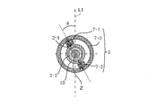
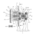
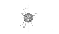
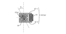
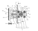
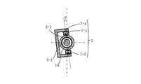
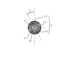
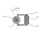
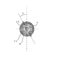
- FIG. 1A is a side cross-sectional view showing a configuration of a main part of an embodiment (Example 1) of a shutoff valve according to the present invention (a state in which a mover is latched in a state where it is moved to one side in a movable axis direction ( FIG. 1B is a cross-sectional view taken along line AA in FIG. 1A. 1C is a cross-sectional view taken along line BB in FIG. 1A.
- FIG. 1B is a cross-sectional view taken along line AA in FIG. 1A.
- FIG. 1C is a cross-sectional view taken along line BB in FIG. 1A.
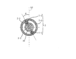
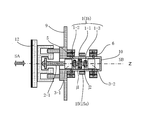
- FIG. 2A is a side cross-sectional view showing the configuration of the main part of one embodiment (embodiment 1) of the shut-off valve according to the present invention (the state in which the mover is latched in a state where it is moved to the other side in the movable axis direction ( FIG. 2B is a cross-sectional view taken along line AA in FIG. 2A. 2C is a cross-sectional view taken along line BB in FIG. 2A.
- FIG. 3 is a side cross-sectional view illustrating an example in which the mover is configured with a plurality of permanent magnets in the first embodiment.
- FIG. 4 is a side cross-sectional view showing an example in which the movable range of the mover is limited in the first embodiment.
- FIG. 5A is a side cross-sectional view illustrating an example in which the stator is a cylindrical permanent magnet in the first embodiment.
- FIG. 5B is a cross-sectional view taken along line AA in FIG. 5A.
- FIG. 5C is a cross-sectional view taken along line BB in FIG. 5A.
- FIG. 6A is a side cross-sectional view illustrating an example in which a stator is configured by using a permanent magnet having a circular magnetic pole surface (segment type permanent magnet) in the first embodiment.
- 6B is a cross-sectional view taken along line AA in FIG. 6A.
- 6C is a cross-sectional view taken along line BB in FIG. 6A.
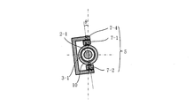
- FIG. 7A is a side cross-sectional view showing an example in which a surface of a pair of permanent magnets opposite to the movable shaft is connected by a yoke having a “U” cross section to form a stator.
- FIG. 7B is a cross-sectional view taken along line AA in FIG. 7A.
- FIG. 7C is a cross-sectional view taken along line BB in FIG. 7A.
- FIG. 8A is a side cross-sectional view showing a modification in the magnetic pole direction of the permanent magnet of the stator.
- FIG. 8B is a cross-sectional view taken along line AA in FIG. 8A.
- 8C is a cross-sectional view taken along line BB in FIG. 8A.
- FIG. 8A is a side cross-sectional view showing an example in which a surface of a pair of permanent magnets opposite to the movable shaft is connected by a yoke having a “U” cross section to form a stator.
- FIG. 9 is a diagram showing an example in which the shape of the other end portion of the yoke facing the movable element from a direction substantially orthogonal to the movable shaft is a flat surface.
- FIG. 10 is a diagram showing an example in which the other end portion of the yoke facing each other with the mover interposed therebetween in a direction substantially orthogonal to the movable shaft is partially connected or integrated.
- FIG. 11 is a diagram illustrating an example in which the shape of the other end portion of the yoke facing the movable element from the direction substantially orthogonal to the movable shaft is asymmetric.
- FIG. 12 is a diagram showing an example in which a notch is provided at the other end of the yoke facing the movable element from a direction substantially orthogonal to the movable shaft.
- FIG. 13 is a diagram showing an example in which the movable shaft does not intersect the line connecting the centers of the end portions of the yokes facing each other with the movable element sandwiched from a direction substantially orthogonal to the movable shaft.
- FIG. 14 is a diagram showing an example in which the center of the yoke end opposed to the movable element in a direction substantially orthogonal to the movable axis is shifted to both sides of the movable element within a plane orthogonal to the movable axis.
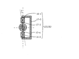
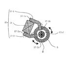
- FIG. 15A is a side cross-sectional view showing an example using a set of electromagnetic coils in which the axes are substantially aligned with the movable shaft in between and the ends of the core are opposed to each other.
- FIG. 15B is a cross-sectional view taken along line AA in FIG. 15A.
- FIG. 15C is a sectional view taken along line BB in FIG. 15A.
- FIG. 16 is a diagram illustrating another configuration example of a mechanism (rotational force transmission suppression mechanism) that suppresses transmission of rotational force to the valve body.
- FIG. 17 is a diagram showing another configuration example of the rotation stop mechanism of the valve body.
- FIG. 18A is a diagram illustrating another configuration example of the rotation stop mechanism of the valve body.
- FIG. 18B is a cross-sectional view taken along the line CC in FIG. 18A.
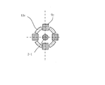
- FIG. 19A is a side cross-sectional view showing a configuration of a main part when the permanent magnet of the mover has four magnetic poles.
- FIG. 19B is a view of FIG. 19A viewed from the left.
- FIG. 19C is a diagram when FIG. 19A is viewed from the right direction.
- FIG. 20 is a diagram showing the arrangement of yokes constituting the mover rotating mechanism when the first and second permanent magnets of the mover have four magnetic poles.
- FIG. 21 is a diagram illustrating an example in which chamfered portions are formed on both the edges of the movable element and the stator that are close to each other.
- FIG. 19A is a side cross-sectional view showing a configuration of a main part when the permanent magnet of the mover has four magnetic poles.
- FIG. 19B is a view of FIG. 19A viewed from the left.
- 22A is a side cross-sectional view showing the configuration of the main part of another example (Example 2) of the shut-off valve according to the present invention.
- 22B is a cross-sectional view taken along line AA in FIG. 22A.
- 22C is a cross-sectional view taken along line BB in FIG. 22A.
- FIG. 1A 1 (1a) is a mover, and shafts 2-1 and 2-2 are connected to both ends thereof.
- the mover 1 is a permanent magnet, and the shafts 2-1 and 2-2 are non-magnetic.
- cylindrical sliding bodies (nonmagnetic members) 3-1 and 3-2 are inserted and fixed (press-fitted) into the shafts 2-1 and 2-2.
- an integrated body composed of the movable element 1, the shafts 2-1 and 2-2, and the sliding bodies 3-1 and 3-2 is referred to as a movable body and is denoted by reference numeral 4.
- the movable body 4 is provided so as to be movable in the axial direction (Z-axis direction) of the shafts 2-1 and 2-2. That is, the movable body 4 (movable element 1) is provided so as to be movable in the movable axis direction with the Z-axis direction as the movable axis direction. Further, it is held rotatably about the Z axis.
- the Z axis is referred to as a movable axis.
- the mover 1 has a cylindrical shape (cylindrical permanent magnet) and is magnetized in the radial direction.
- magnetic poles facing each other across the movable axis Z are arranged in a direction orthogonal to the movable axis Z, and one surface side (upper side in the state of FIG. 1A) facing the movable axis Z is S.
- the other side of the pole (the lower side in the state of FIG. 1A) is the N pole.
- 5 is a first stator provided on one side (SA) in the movable axis direction across the mover 1
- 6 is provided on the other (SB) side in the movable axis direction across the mover 1.
- the first stator 5 has a magnetic pole direction perpendicular to the movable axis Z, the magnetic pole directions are the same, and the movable element 1 is perpendicular to the movable axis Z across the movable axis Z. It is composed of a pair of permanent magnets 7-1 and 7-2 and a cylindrical yoke 7-3 that are spaced apart so as not to contact each other.
- the N pole of the permanent magnet 7-1 is the mover 1 side and the S pole is the opposite side of the mover 1
- the S pole of the permanent magnet 7-2 is the mover 1 side and the N pole is movable.
- the side is opposite to the child 1 and is fixed to the inner peripheral surface of a cylindrical yoke 7-3.
- the cylindrical yoke 7-3 has an effect that the magnetic fluxes of the permanent magnets 7-1 and 7-2 work efficiently and suppress the leakage of magnetic flux to the surroundings.
- the second stator 6 has a magnetic pole direction perpendicular to the movable axis Z, the magnetic pole directions are the same, and the movable element 1 is perpendicular to the movable axis Z across the movable axis Z. It is composed of a pair of permanent magnets 8-1 and 8-2 and a cylindrical yoke 8-3 which are arranged so as not to contact each other.
- the S pole of the permanent magnet 8-1 is on the mover 1 side
- the N pole is on the opposite side of the mover 1
- the N pole of the permanent magnet 8-2 is on the mover 1 side
- the S pole is movable.
- the side is opposite to the child 1 and is fixed to the inner peripheral surface of the cylindrical yoke 8-3.
- the cylindrical yoke 8-3 has an effect that the magnetic fluxes of the permanent magnets 8-1 and 8-2 work efficiently and suppresses magnetic flux leakage to the surroundings.
- the set of permanent magnets 7-1 and 7-2 of the first stator 5 and the set of permanent magnets 8-1 and 8-2 of the second stator 6 are respectively The permanent magnets are arranged on one side and the other side in the movable axis direction with the mover 1 therebetween so that the magnetic poles facing the movable axis direction are different from each other.
- the length 1 of the movable element 1 in the movable axis direction is such that the permanent magnets 7-1 and 7 constituting the first stator 5 arranged on one side and the other side of the movable axis direction with the movable element 1 interposed therebetween. -2 and the opposing surface distance L of the permanent magnets 8-1 and 8-2 constituting the second stator 6.
- the directions of the magnetic poles of the permanent magnets 7-1, 7-2 and 8-1, 8-2 of the stators 5 and 6 are perpendicular to the movable axis Z as shown in FIG. 1B.
- the direction is the reference direction, it is inclined by ⁇ with respect to this reference direction.
- the movable body 4 is a compartment formed by a flange (nonmagnetic member) 9 and a seal tube (nonmagnetic member) 10, that is, a space where one end communicates with the opening 9a of the flange 9 and the other end is closed.
- the shaft 2-1 of the movable body 4 extends outside the compartment 11 through the opening 9 a of the flange 9.
- the seal tube 10 is integrally or hermetically connected so that one end communicates with the opening 9a of the flange 9, and the other end is closed.
- the flange 9 has a flange surface as an attachment portion to the flow path.
- reference numeral 12 denotes a flow path by contact / separation between a valve rubber disposed on the surface side of the movable element 1 in the direction of the movable axis and a valve seat (not shown) formed in the flow path.
- a shaft 2-1 of the movable body 4 is rotatably attached to the valve body 12. That is, the shaft 2-1 of the movable body 4 passes through the through hole 12a and reaches the inside of the valve body 12, and a spherical surface (curved surface) portion 13a and a retaining ring 13b are attached to the tip of the shaft. It is considered to be a part.
- the valve body 12 has a plurality of guide holes 12b formed on the back side thereof, and pins 14 provided on the flange 9 are inserted into the holes 12b.
- the valve body 12 is guided to move in the direction of the movable axis by using a pin 14 provided on the flange 9 as a guide, and the rotation about the movable axis Z is restricted (blocked) by the pin 14.
- reference numeral 15 (15a) designates a magnetic field (hereinafter referred to as a permanent magnet) of the permanent magnet of the mover 1 by rotating the mover 1 by applying a magnetic field in the forward and reverse directions to the mover 1 from a direction substantially orthogonal to the movable axis Z.
- This is a mover rotating mechanism that replaces the arrangement of the mover 1 (referred to simply as the magnetic pole of the mover 1) between the first arrangement and the second arrangement.
- the mover rotating mechanism 15 includes an electromagnetic coil 16, a core 22 inserted through the electromagnetic coil 16, and one end 17-1a at one end and the other end of the core 22.
- And 17-2a are electromagnets composed of yokes 17-1 and 17-2 connected or integrated.
- the other ends 17-1b and 17-2b of the yokes 17-1 and 17-2 are opposed to each other with the mover 1 sandwiched from a direction substantially perpendicular to the movable axis Z. . That is, they are generally opposed to a pair of adjacent magnetic poles on the outer peripheral surface of the mover 1.
- the other end portions 17-1b and 17-2b of the yokes 17-1 and 17-2 have an arc shape in accordance with the shape of the outer peripheral surface of the mover 1. That is, the surfaces of the other ends 17-1b and 17-2b of the yokes 17-1 and 17-2 facing the mover 1 are arcuate when viewed from the direction along the movable axis Z.
- FIG. 1A shows a state in which the mover 1 is rotated by the mover rotating mechanism 15 and the magnetic pole arrangement of the mover 1 is switched to the first arrangement.
- the magnetic pole of the mover 1 (cylindrical permanent magnet) has an S pole on the upper side and an N pole on the lower side.
- the mover 1 is magnetically attracted to the stator 5 from the outside of the compartment 11. That is, the stator 5 pulls the movable element 1 and latches (sucks and holds) it.
- the valve body 12 is stopped (maintains the closed state) in a state of moving to one side of the movable axis direction (left direction shown in FIG. 1A), that is, in a state of moving to the valve closing side.
- the mover 1 In the non-excited state of the electromagnetic coil 16, the mover 1 is stationary in a state where the direction of the magnetic pole is inclined by ⁇ along the direction of the magnetic pole of the stator 5 due to the magnetic attraction force with the stator 5. is doing.
- the mover 1 leaves the first stator 5, approaches the second stator 6, and is combined with the magnetic attraction force generated between the second stator 6 and the second stator 6.
- the force for moving the mover 1 from the first stator 5 side to the second stator 6 side is greater than twice the magnetic repulsion force by the magnetic attraction force.
- the power of the mover 1 is transmitted to the valve body 12 by the shaft 2-1, and the valve body 12 is moved to the other side (the valve opening side) in the movable axis direction. That is, the valve body 12 is moved to the open position. Then, the valve element 12 is held in the open position by the latch of the movable element 1 by the second stator 6 (the valve open state is maintained).
- FIG. 2A is a state in which the energization of the electromagnetic coil 16 is interrupted after the mover 1 is rotated by the mover rotating mechanism 15, that is, the energization of the electromagnetic coil 16 is interrupted (non-excited state). Is shown.
- the movable element 1 is stationary with the magnetic pole direction inclined by ⁇ along the magnetic pole direction of the stator 6 by the magnetic attractive force between the movable element 1 and the stator 6.
- the mover 1 is rotated (rotated 180 °) by the mover rotating mechanism 15 and the arrangement of the magnetic poles of the mover 1 is switched to the first arrangement. That is, it is assumed that the position of the magnetic pole of the mover 1 (cylindrical permanent magnet) is changed and the upper side is returned to the S pole and the lower side is returned to the N pole. Then, the magnetic attractive force between the mover 1 and the second stator 6 disappears, and a magnetic repulsive force is generated between the mover 1 and the second stator 6.
- the mover 1 leaves the second stator 6, approaches the first stator 5, and is combined with the magnetic attraction force generated between the first stator 5 and the first stator 5.
- the first stator 5 is attracted magnetically and is latched on the first stator 5 side (see FIG. 1A).
- the force that moves the mover 1 from the second stator 6 side to the first stator 5 side is greater than twice the magnetic repulsion force by the magnetic attraction force.
- the power of the mover 1 is transmitted to the valve body 12 by the shaft 2-1, and the valve body 12 is moved to one side (the valve closing side) in the movable axis direction. That is, the valve body 12 is moved to the closed position. Then, the valve element 12 is held in the closed position by the latch of the movable element 1 by the first stator 5 (the valve closed state is maintained).
- the mover 1 moves in a non-contact manner with the first stator 5 and the second stator 6, and one side of the mover 1. Is latched (maintaining the valve closed state), and the other side is latched (maintaining the valve open state).
- the mover 1 when the electromagnetic coil 16 is in a non-excited state, the mover 1 is stationary with its magnetic pole direction tilted by approximately ⁇ , so that it receives the electromagnetic force from the mover rotating mechanism 15 and rotates efficiently.
- the angle of intersection between the center of the magnetic pole on the outer peripheral surface of the mover 1 and the line connecting the movable axis Z is ⁇ , and the center of the other end 17-2b of the yoke 17-2 and the movable axis Z And the line connecting the movable axis Z and the center of the magnetic pole of the outer peripheral surface of the mover 1 substantially opposite to the other end 17-2b of the yoke 17-2 is ⁇ Therefore, the electromagnetic force generated when the electromagnetic coil 16 is in an excited state efficiently acts on the rotation of the mover 1.
- ⁇ is the intersection angle between the center of the magnetic pole on the outer periphery of the permanent magnet of the mover 1 at least partially facing the portion 17-1b and the line connecting the movable axis Z.
- the crossing angle ⁇ is preferably in a range larger than 0 ° and smaller than 90 °.
- the mover 1 moves in the direction of the second stator 6 in a state where the arrangement of the magnetic poles is in the first arrangement.
- a magnetic repulsive force is generated between the mover 1 and the second stator 6.
- the mover 1 moves away from the second stator 6, approaches the first stator 5, and the mover 1 is moved by the resultant force of the magnetic attraction force generated between the mover 1 and the first stator 5. It is returned to one side (valve closing side) in the axial direction.
- the movable element 1 remains in the other direction in the movable axis direction. Instead of being latched at the position moved to the side, it automatically returns to the latch (original latched state) at the position moved to one side (valve closing side) in the movable axis direction.
- the mover 1 moves in the direction of the first stator 5 in a state where the arrangement of the magnetic poles is in the second arrangement.
- a magnetic repulsive force is generated between the mover 1 and the first stator 5.
- the mover 1 moves away from the first stator 5, approaches the second stator 6, and the mover 1 is moved by the resultant force with the magnetic attractive force generated between the second stator 6. It is returned to the other side (the valve opening side) in the axial direction.
- the movable element 1 since an impact or temporary excessive force is applied to one side (valve closing side) in the movable axis direction, and the movable element 1 moves to one side in the movable axis direction, the movable element 1 remains in one of the movable axis directions. Instead of being latched at the position moved to the side, it automatically returns to the latch (original latched state) at the position moved to the other side (the valve opening side) in the movable axis direction.
- the shut-off valve of the present embodiment if the arrangement of the magnetic poles of the mover 1 is not changed by rotating the mover 1, the position moved from one side of the mover 1 to the position moved to the other side is changed. Latch switching cannot be performed from the position moved to the other side to the position moved to the one side. Further, without changing the arrangement of the magnetic poles of the mover 1, the mover 1 latched at the position moved to one side is moved to the other side, and the mover 1 latched at the position moved to the other side. When movement to one side occurs, the original latch state is automatically restored.
- a lock mechanism called rotation of the mover 1 is added to the movement of the mover 1 in the movable axis direction, that is, to change the open / close state of the shut-off valve, and this lock mechanism is added.
- the valve open / closed state can be reliably maintained, and safety is improved.
- permanent magnets are used for both the mover 1 and the stators 5 and 6, and the main power for moving the mover 1 in the direction of the movable axis is the stator (permanent magnet).
- stator permanent magnet
- a magnetic field is instantaneously applied from a position close to the mover (permanent magnet) 1 so as to generate a rotational torque necessary for changing the arrangement of the magnetic poles of the mover 1. It is only necessary to do this, and (in principle) it can be operated with less electric power than when it is used as the main power for movement in the direction of the movable axis with a conventional solenoid (Patent Document 1) or a stepping motor (Patent Document 2). It becomes possible. In particular, with respect to Patent Document 2, since the voltage (pulse) application time is significantly shortened, power saving can be realized. Therefore, it is suitable for a battery-driven shut-off valve.
- the electrical (and operation sequence) specifications for opening and closing may be almost the same, so the configuration of the control circuit can be simplified. That is, the technique of Patent Document 1 requires a booster circuit having a large capacitor only when the valve is opened, and the technique of Patent Document 2 requires a step motor driver circuit, which complicates the configuration of the control circuit. .
- the shut-off valve of the present embodiment is basically possible only with a transistor switching circuit, and the configuration of the control circuit can be simplified.
- the movable body 4 moves in the compartment 11. For this reason, the movement of the mover 1 and the shafts 2-1 and 2-2 may change the pressure in the compartment 11 and hinder the operation of the mover 1. In order to prevent this, in this embodiment, although not shown, slits and chamfering are performed on the sliding bodies 3-1, 3-2 and the shafts 2-1, 2-2. Allows gas flow.
- the sliding bodies 3-1 and 3-2 are provided on the shafts 2-1 and 2-2 to reduce the size, and the sliding body 3-
- the outer surface of 1, 3-2 and the inner surface of the compartment 11 guide the movement of the movable body 4.
- a bush (linear guide) is installed (fixed) in the compartment 11, and the shaft 2-
- a general configuration in which the movable body 4 is guided by the outer peripheral surfaces 1 and 2-2 and the inner peripheral surface of the bush (linear guide) may be employed.
- the permanent magnet of the mover 1 has a columnar shape, but may have a cylindrical shape. Since the permanent magnet of the mover 1 is formed in a columnar shape or a cylindrical shape, the distance from the inner peripheral surfaces of the stators 5 and 6 arranged on the outside can be set close to the magnetic efficiency. Is convenient for miniaturization. Further, in the case of a cylindrical shape, the magnetic force becomes weaker depending on the volume and the distance between the magnetic poles, but since it can be fixed through the shaft on the inside, the shaft alignment and connection with the shaft are facilitated and the assembly is facilitated.
- the shaft also has a tubular shape so that the gas in the compartment 11 can flow, and the pressure change in the compartment 11 due to the movement of the movable body 4 as described above can be suppressed.
- the permanent magnet of the mover 1 may be rectangular, but it can be said that a cylindrical or cylindrical shape is the shape with the best magnetic and space efficiency.
- the permanent magnets 7-1 and 7-2 and the second stator 6 constituting the first stator 5 have a length l in the movable axis direction of the permanent magnet of the mover 1. Is equal to or less than the facing surface distance L of the permanent magnets 8-1 and 8-2. By setting l ⁇ L, the force generation efficiency in the movable axis direction can be improved.
- the mover 1 is constituted by one permanent magnet, but it is not necessarily constituted by one permanent magnet.
- the configuration becomes simple and the assembly can be facilitated.
- FIG. 3 shows an example in which the mover 1 is composed of a plurality of permanent magnets.
- the mover 1 is composed of three columnar permanent magnets 1-1, 1-2, and 1-3, and the permanent magnet 1-1 is located at the center of the movable axis.
- the permanent magnets 1-2 and 1-3 that are shorter than the permanent magnet 1-1 (length in the movable axis direction) are arranged on both sides of the permanent magnet 1-1. .
- the permanent magnet 1-1 and the permanent magnets 1-2 and 1-3 have different diameters (lengths in the direction of the opposite magnetic poles), and the diameter of the permanent magnet 1-1 is the permanent magnet. It is larger than the diameters of 1-2 and 1-3. Then, the permanent magnet 1-1 and the permanent magnet 1-2 are coupled with the nonmagnetic coupling portion j1 interposed therebetween, and the permanent magnet 1-1 and the permanent magnet 1-3 are coupled with the nonmagnetic coupling portion j2 interposed therebetween. is doing.
- the central permanent magnet 1-1 is a permanent magnet for rotating the mover, and the permanent magnets 1-2, 1-3 on both sides are linearly moved in the direction of the movable axis of the mover. Permanent magnet for holding.
- the mover 1 can be rotated (magnetic pole reversal) with a small force.
- the permanent magnet 1-1 is advantageous in terms of torque with respect to the force that prevents rotation caused by the attractive force acting between the permanent magnets 1-2 and 1-3 and the stators 5 and 6, the weaker force That is, it can be rotated with low power, and the power saving mechanism 15 can save power.
- the movable element 1 (1b) having the structure as shown in FIG. 3 individual permanent magnets are selected for rotation, movement (linear movement), and holding, and the degree of design freedom is increased. Not only can it be widened, but it is possible to reduce the volume of the permanent magnet material and reduce the cost and weight when the length and diameter of the permanent magnet are large.
- FIG. 4 shows an example in which the movable range of the mover 1 is limited.
- the movement of the movable element 1 toward one side (the valve closing side) in the movable axis direction is regulated by using the valve seat 18 on which the valve body 12 is seated as a mechanical stopper, and the movable element 1 is moved in the movable axis direction.
- the movement to the other side (valve opening side) is regulated by using a spacer 19 provided on the end face (closed face) of the seal tube 10 as a mechanical stopper, thereby restricting the movable range of the mover 1. .
- a set of permanent magnets 7-1 and 7-2 is fixed to the inner peripheral surface of a cylindrical yoke 7-3 to form a first stator 5, and a set of permanent magnets 8 is used.
- -1 and 8-2 are fixed to the inner peripheral surface of the cylindrical yoke 8-3 to form the second stator 6.
- the first stator 5 and the second stator 6 are fixed to the cylindrical permanent It is good also as a magnet.
- FIG. 5 shows an example in which the stators 5 and 6 are cylindrical permanent magnets.
- the first stator 5 is arranged in a cylindrical shape that is arranged with the movable shaft Z and the center approximately aligned, and is radially magnetized with an inner diameter that does not contact the movable element 1.
- the permanent magnet 5a is used (see FIG. 5B).
- the upper surface of the inner diameter facing the movable shaft Z side of the stator 5 is the N pole and the lower surface is the S pole.
- the second stator 6 is also a cylindrical permanent magnet 6a that is arranged so that its center is aligned with the movable axis Z and is radially magnetized with an inner diameter that does not contact the movable element 1. Yes.
- the upper surface of the inner diameter facing the movable axis Z side of the stator 6 is the S pole and the lower surface is the N pole.
- the shape of the permanent magnet is different, but the cylindrical permanent magnet 5 a of the first stator 5 and the cylindrical permanent magnet of the second stator 6 are the same as in the configuration of FIG. 1.
- the magnet 6a has a magnetic pole direction orthogonal to the movable axis Z, and one of the movable axes in the direction of the movable axis with the mover 1 sandwiched so that the magnetic poles opposed to the movable axis directions of the permanent magnets have different polarities. It is arrange
- a pair of permanent magnets 7-1, 7-2 and 8-1, 8-2 have a circular magnetic pole surface.
- An arc-shaped permanent magnet may be used. Also by using such a segment type permanent magnet, the magnetic efficiency between the movable element 1 and the stators 5 and 6 is improved.
- the surface of the pair of permanent magnets 7-1 and 7-2 opposite to the movable axis Z is a yoke 7-4 having a “U” -shaped cross section.
- the first stator 5 is connected by connecting the surfaces of the pair of permanent magnets 8-1 and 8-2 in the direction opposite to the movable axis Z by a yoke 8-4 having a “U” cross section.
- Two stators 6 may be used.
- FIG. 8 shows a modification of the magnetic pole direction of the permanent magnet of the stator.
- a pair of segment-type permanent magnets 7-1 ′ and 7-2 ′ whose arc-shaped concave surfaces are opposed to each other are arranged in a direction perpendicular to the movable axis Z across the movable axis Z.
- the magnetic pole direction is parallel to the movable axis Z, the magnetic pole directions are opposite to the other, and the set of permanent magnets 7-1 'and 7-2'
- the first stator 5 is provided with a ring-shaped yoke 7-5 on one side in the direction of the movable axis and semi-ring-shaped yokes 7-6a and 7-6b on the other side.
- a pair of segment-type permanent magnets 8-1 ′ and 8-2 ′ with their arcuate concave surfaces facing each other is movable in a direction perpendicular to the movable axis Z with the movable axis Z in between.
- the magnetic pole direction is parallel to the movable axis Z and the magnetic pole direction is opposite to the other, so that the magnetic pole direction is opposite to the other.
- a ring-shaped yoke 8-5 is provided on the other side in the direction of the movable axis 2 ', and semi-ring-shaped yokes 8-6a and 8-6b are provided on one side to form the second stator 6, and the first stator 5
- the pair of permanent magnets 7-1 ′ and 7-2 ′ and the pair of permanent magnets 8-1 ′ and 8-2 ′ of the second stator 6 are opposed to each other in the direction of the movable axis.
- the moving magnetic poles are arranged on one side and the other side in the direction of the movable axis so that the magnetic poles are different from each other.
- one of the yokes 7-5 and 7-6a and 7-6b in the first stator 5 and the yokes 8-5 and 8-6a and 8-6b in the second stator 6 are either. May be provided. Further, instead of the segment-type permanent magnet, a square-type permanent magnet can be similarly configured.
- the shapes of the other ends 17-1b and 17-2b of the yokes 17-1 and 17-2 are arc-shaped to match the shape of the outer peripheral surface of the mover 1. As shown, the shapes of the other ends 17-1b and 17-2b of the yokes 17-1 and 17-2 may be flat. If the shapes of the other end portions 17-1b and 17-2b of the yokes 17-1 and 17-2 are arcuate, the generation efficiency of the rotational force is improved (it can be rotated with low magnetic flux (low power)). it can).
- both end portions of the arcs of the opposing yokes 6-1 and 6-2 have a small cross-sectional area (high magnetic resistance) and face each other close to each other in order to increase the rotational force.
- the arc shape is formed concentrically with the outer periphery of the mover 1 in order to improve the rotation efficiency.
- a space is provided in the abutting portion of the other ends 17-1b and 17-2b of the yokes 17-1 and 17-2.
- Connection or integration may be performed without providing a space.
- the butted portions of the other ends 17-1b and 17-2b of the yokes 17-1 and 17-2 are connected or integrated, that is, the other ends 17-1b and 17- of the yokes 17-1 and 17-2 are connected.
- 2b is partially connected or integrated, the rotational force generation efficiency is slightly reduced, but positioning and assembly are facilitated.
- the setting of the crossing angle ⁇ when the electromagnetic coil 16 is in the non-excited state is performed by setting the permanent magnets 7 (7-1, 7-2) and 8 (8-1, 8) of the stators 5 and 6. -2)
- the rotation angle position (the direction of the magnetic pole) about the movable axis Z is set.
- the yokes 17-1 and 17-2 are asymmetrically shaped or arranged with respect to each other. It may be. An example is shown in FIGS.
- the surfaces of the other ends 17-1b and 17-2b of the yokes 17-1 and 17-2 that are at least partially opposed to the magnetic poles on the outer periphery of the permanent magnet of the mover 1 are movable.
- the crossing angle ⁇ is generated by setting a stable position where the rotational angle of the mover 1 is balanced by the working suction force.
- the other ends 17-1b and 17-2b of the yokes 17-1 and 17-2 are movable to a surface at least partially facing the magnetic pole on the outer periphery of the permanent magnet of the mover 1.
- the crossing angle ⁇ is generated by setting a stable position where the rotation angle of the mover 1 is balanced by the attractive force acting between the movable member 2b and the movable member 2b.
- the crossing angle ⁇ is set with the asymmetric shapes or arrangements of the yokes 17-1 and 17-2, the holding torque for holding the mover 1 at a predetermined angular position works, so that the electromagnetic coil It is possible to prevent rotation due to factors other than excitation and prevent malfunction.
- the directions of the magnetic poles of the stators 5 and 6 are not shown, but in order to maximize the generated force in the movable axis Z direction of the mover 1, the stator 5 , 6 are preferably set so that the directions of the magnetic poles of the movable element 1 and the magnetic poles of the mover 1 are also matched.
- the mover rotating mechanism 15 includes an electromagnetic coil 16 and yokes 17-1 and 17-2, and the other end 17 of the yokes 17-1 and 17-2.
- -1b and 17-2b are opposed to each other with the mover 1 sandwiched from a direction substantially orthogonal to the movable axis Z, such a configuration is not necessarily required.
- FIG. 15 FIG. 15 (FIGS. 15A, 15B, and 15C) as an example applied to the configuration shown in FIG. 7, the core 17-3 and the core 17-3 A set of electromagnetic coils 16-1 and 16-2 arranged so that one ends of 17-4 are opposed to each other, and a yoke 17- connecting the other ends of the cores 17-3 and 17-4 of the set of electromagnetic coils. 5 may constitute the mover rotating mechanism 15 (15b).
- the shaft 2-1 rotates about the movable axis Z and moves in one direction of the movable axis Z
- the spherical surface (curved surface) portion 13a at the tip of the shaft 2-1 moves the movable axis Z of the shaft 2-1.
- the rotation around the center is received by sliding between the spherical surface (curved surface) 13a at the tip of the shaft 2-1 and the inner surface of the through hole 12a of the valve body 12, and the force in one direction of the movable axis Z is transmitted to move the valve body 12 Move in one direction (valve closing side) of axis Z.
- a bearing 20 is attached to the tip of the shaft 2-1, thereby constituting a rotational force transmission suppressing mechanism. While transmitting the force in the direction of the movable axis Z via the shaft 2-1 of the mover 1 to the body 12, the transmission of the rotational force around the movable axis Z via the shaft 2-1 of the mover 1 is received. You may do it. Since the bearing 20 has less friction, the mover 1 can be rotated with low power, and power saving of the mover rotating mechanism 15 can be achieved.
- a pin 21 is provided on the back surface side of the valve body 12, and the pin 21 is inserted into a hole 9 b provided in the flange 9 to guide the movement of the valve body 12 in the movable axis direction.
- the rotation of the valve body 12 around the movable axis Z may be restricted (blocked).
- FIG. 18 (FIGS. 18A, 18B, and 18C)
- a plurality of convex portions 12c provided on the back surface side of the valve body 12 and a plurality of convex portions 9c provided on the flange 9.
- the movement of the valve body 12 in the direction of the movable axis may be guided, and the rotation of the valve body 12 around the movable axis Z may be restricted (blocked).
- the permanent magnet constituting the mover 1 has two magnetic poles. However, four or more magnetic poles (for example, cylindrical radial magnetization (in the case of a cylinder, there is a magnetic pole on the inner peripheral side). It may be a multi-pole permanent magnet of magnetic poles)).
- FIG. 19 shows a configuration diagram of a main part when the permanent magnet of the mover 1 is a cylindrical permanent magnet and the cylindrical permanent magnet has four magnetic poles.
- the mover rotating mechanism 15 and the seal tube 10 shown in FIG. 1 are omitted.
- the permanent magnet of the mover 1 (1c) is divided into four in the circumferential direction, and magnetic poles are formed on adjacent circumferential surfaces at 90 ° intervals.
- the S pole is formed on the first circumferential surface (upper surface in FIG. 19A) adjacent at 90 ° intervals, and the N pole is formed on the second surface (left surface in FIG. 19B).
- the S pole is formed on the third surface (the lower surface in FIG. 19B), and the N pole is formed on the fourth surface (the right surface in FIG. 19B).
- the stators 5 and 6 are also formed as cylindrical permanent magnets having a total of 8 magnetic poles with 4 magnetic poles on the inner peripheral surface and 4 magnetic poles on the outer peripheral surface. That is, the inner peripheral surface of the stator 5 is divided into four in the circumferential direction, and magnetic poles are formed on adjacent circumferential surfaces at 90 ° intervals.
- the N pole is formed on the first circumferential surface (the upper surface in FIG. 19B) adjacent at 90 ° intervals
- the S pole is formed on the second surface (the left surface in FIG. 19B).
- An N pole is formed on the third surface (the lower surface in FIG. 19B), and an S pole is formed on the fourth surface (the right surface in FIG. 19B).
- the inner peripheral surface of the stator 6 is divided into four in the circumferential direction, and magnetic poles are formed on adjacent circumferential surfaces at intervals of 90 °.
- an S pole is formed on the first circumferential surface (the upper surface in FIG. 19C) adjacent at 90 ° intervals, and an N pole is formed on the second surface (the left surface in FIG. 19C).
- An S pole is formed on the third surface (lower surface in FIG. 19C), and an N pole is formed on the fourth surface (right surface in FIG. 19C).
- the other ends 17-1b and 17-2b of the yokes 17-1 and 17-2 are as shown in FIG. It arrange
- the center of the other end 17-1b of the yoke 17-1 and the movable axis Z are orthogonal to each other when the electromagnetic coil 16 is not excited.
- the line connecting the center of the other end 17-2b of the yoke 17-2 and the movable axis Z so as to be perpendicular to the angle 17 is substantially opposite to the other end 17-2b of the yoke 17-2. It is desirable that the crossing angle between the center of the magnetic pole on the outer peripheral surface of the permanent magnet of the mover 1 and the line connecting the movable axis Z so as to be orthogonal is ⁇ and positioned.
- a chamfered portion may be formed on both or one of the adjacent edges of the movable element 1 and the stators 5 and 6.
- FIG. 21 shows an example in which chamfered portions are formed on both the adjacent edges of the movable element 1 and the stators 5 and 6 in the configuration shown in FIG.
- FIG. 21 is a side sectional view of the main part.
- chamfered portions 5 a and 6 a are formed at the edges of the stator 5 (cylindrical permanent magnet) and the stator 6 (cylindrical permanent magnet) that are close to and opposed to the mover 1. . Further, chamfered portions 1-a and 1-b are formed at edges that are close to and opposed to the stator 5 (cylindrical permanent magnet) and the stator 6 (cylindrical permanent magnet) of the mover 1.
- FIG. 22 shows a main part of another embodiment (embodiment 2) of the shutoff valve according to the present invention.
- the mover 1 (1d) is composed of a permanent magnet 1-A for rotation and a permanent magnet 1-B for linear motion and holding, and the permanent magnet 1-A for rotation
- the permanent magnet 1-B for linear motion / holding is the permanent magnet 1-A for rotation as one side in the movable axis direction
- the permanent magnet 1-B for linear motion / hold is as the other side in the movable axis direction.
- the nonmagnetic coupling portion j3 is sandwiched therebetween.
- the distance between the magnetic poles facing each other across the movable axis Z of the permanent magnet 1-A for rotation is the same as the distance between the movable axes Z of the permanent magnet 1-B for linear motion / holding.
- the mover rotating mechanism 15 is provided for the permanent magnet 1-A for rotation, and the first fixed for the permanent magnet 1-B for linear motion / holding.
- a child 5 and a second stator 6 are provided.
- the stators 5 and 6 are cylindrical permanent magnets. The other configuration is the same as that of the first embodiment, and is omitted.
- FIG. 22A shows a state in which the mover 1 is rotated by the mover rotating mechanism 15 and the arrangement of the magnetic poles of the permanent magnet 1-B of the mover 1 is switched to the first arrangement.
- the magnetic pole of the permanent magnet 1-B of the mover 1 has an S pole on the upper side and an N pole on the lower side.
- the permanent magnet 1-B of the mover 1 is magnetically attracted to the stator 5 from the outside of the compartment 11. That is, the permanent magnet 1-B of the mover 1 is pulled and latched (attracted / held).
- the valve body 12 is stopped (maintained in the closed state) in a state where it has moved to one side of the movable axis direction (left direction shown in FIG. 22A), that is, in a state where it has moved to the valve closing side.
- the power of the mover 1 is transmitted to the valve body 12 by the shaft 2-1, and the valve body 12 is moved to the other side (the valve opening side) in the movable axis direction. Then, the valve element 12 is held in the open position (the valve open state is maintained) by the latch of the permanent magnet 1-B of the mover 1 by the second stator 6.
- the magnetic attractive force between the permanent magnet 1-B of the mover 1 and the second stator 6 disappears, and the magnetic force between the permanent magnet 1-B of the mover 1 and the second stator 6 is lost. A repulsive force is generated.
- the permanent magnet 1-B of the mover 1 leaves the second stator 6, approaches the first stator 5, and is combined with the magnetic attraction force generated between the first stator 5 and the first stator 5. It goes to the first stator 6 side, is magnetically attracted to the first stator 5, and is latched on the first stator 5 side.
- the power of the mover 1 is transmitted to the valve body 12 by the shaft 2-1, and the valve body 12 is moved to one side (the valve closing side) in the movable axis direction. Then, the valve element 12 is held in the closed position (maintaining the valve closed state) by the latch of the permanent magnet 1-1 of the movable element 1 by the first stator 5.
- the distance between the opposing magnetic poles across the movable axis Z of the permanent magnet 1-A is larger than the distance between the opposing magnetic poles across the movable axis Z of the permanent magnet 1-B.
- the permanent magnet 1-A is advantageous in terms of torque against the force that prevents rotation caused by the attractive force acting between the permanent magnet 1-B and the stators 5 and 6, so that a weaker force, that is, low power Thus, it is possible to reduce the power consumption of the mover rotating mechanism 15.
- the stators 5 and 6 are cylindrical permanent magnets.
- the permanent magnets are fixed to the inner peripheral surface of the cylindrical yoke.
- the cylindrical yokes of the stators 5 and 6 may be connected or integrated in the direction of the movable axis. Needless to say, in the second embodiment, as in the first embodiment, various modifications can be considered.
- the movable element 1, the stators 5, 6 and the movable element rotating mechanism 15 constitute the bistable moving mechanism 30.
- first position When latched at a position moved to one side in the movable axis direction (first position) and when latched at a position moved to the other side in the movable axis direction (second position)
- second position When latched at a position moved to the other side in the movable axis direction (second position)
- the structure is symmetrical to the direction, but depending on the application and specifications, the balance of the size, shape, and arrangement of the permanent magnets related to the first and second positions can be changed to The characteristics of the return (valve closing / opening) operation may be changed.
- gas pressure back pressure
- a greater force is required when opening the valve than when the valve is closed. It is more efficient to make asymmetrical. It is also possible to set by means of a means for limiting the movable range of the mover 1 as shown in FIG.
- the bistable moving mechanism 30 shown in the first embodiment instead of the bistable moving mechanism 30 shown in the first embodiment, it is arranged in the compartment 11, is movable in the direction of the movable axis, and is held rotatably around the movable axis.
- a plurality of magnetic poles are arranged so as to sandwich the movable axis Z in a direction perpendicular to the movable axis Z, and the first permanent magnet 1-B and the second second magnet are spaced apart from each other in the movable axis direction and connected to each other by a nonmagnetic member.
- a permanent magnet 1-A is provided, and the distance between the opposing magnetic poles across the movable axis Z of the second permanent magnet 1-A is between the opposing magnetic poles across the movable axis Z of the first permanent magnet 1-B.
- a magnetic field is applied to the mover 1 (1d) that is larger than the distance and the second permanent magnet 1-A to rotate the mover 1 (1d), and the first permanent magnet 1-B and the second permanent magnet 1-B are rotated.
- the magnet 1-B is composed of a member including a permanent magnet that magnetically repels the first permanent magnet 1-B.
- the first permanent magnet 5 and the first permanent magnet 1-B are located on the other side in the movable axis direction, and the magnetic pole arrangement of the first permanent magnet 1-B is in the second arrangement.
- the bistable movement mechanism 40 provided with the 2nd stator 6 comprised with the member containing a magnet is used.
- the permanent magnets of the mover 1 and the permanent magnets of the stators 5 and 6 of the bistable moving mechanisms 30 and 40 are arranged so as not to contact each other. For this reason, mechanical shock is not applied to the magnet during operation and state maintenance, and deterioration of the characteristics of the magnet can be suppressed. In addition, the impact force and attracting sound to the magnet are suppressed, and because it can be maintained in a state of compliance, there is an advantage that a mechanical buffer mechanism or a spring mechanism can be omitted like a conventional solenoid. Arise.
- the permanent magnet is, for example, a rare earth magnet or ferrite magnet such as neodymium or samarium cobalt, or a bonded magnet formed by mixing a resin with these magnetic powders.
- the yoke is made of a soft magnetic material (for example, an electromagnetic steel plate, electromagnetic soft iron, permalloy, etc.) having a large saturation magnetic flux density and magnetic permeability, a small coercive force, and a small magnetic hysteresis.
- the nonmagnetic member such as the shaft is made of, for example, aluminum, SUS316 (L), brass, resin, or the like.
- the non-magnetic member can be made of a slightly magnetic material (for example, SUS304) instead of the non-magnetic material as described above, and the performance is lowered, but should be selected from the viewpoint of cost. Is also possible.
- the valve body may be a single valve structure or a sub-valve structure having a pilot valve (relief valve).
- valve body 12 is configured not to rotate.
- valve body 12 is configured to rotate without the rotational force transmission suppression mechanism and the valve body rotation stop mechanism. You can also.
- the pilot valve relievef valve
- the main valve may not rotate.
- shut-off valve of the present invention is suitable for use in gas emergency shut-off devices installed in city gas and LP gas supply lines and gas meters, but can also be applied to shut-off valves for other uses.
- SYMBOLS 1 ... Movable element, 1-1, 1-2 ... Permanent magnet, 2-1, 2-2 ... Shaft, 3-1, 3-2 ... Sliding body, 4 ... Movable body, 5 ... 1st stator, 6 ... second stator, 7-1, 7-2 ... permanent magnet, 7-3 ... yoke, 8-1,8-2 ... permanent magnet, 8-3 ... yoke, 9 ... flange, 10 ... seal tube , 11 ... compartment, 12 ... valve body, 15 ... mover rotating mechanism, 16 ... electromagnetic coil, 17-1, 17-2 ... yoke, 30, 40 ... bistable moving mechanism.
Landscapes
- Engineering & Computer Science (AREA)
- Physics & Mathematics (AREA)
- Electromagnetism (AREA)
- Power Engineering (AREA)
- General Engineering & Computer Science (AREA)
- Mechanical Engineering (AREA)
- Magnetically Actuated Valves (AREA)
- Electromagnets (AREA)
- Connection Of Motors, Electrical Generators, Mechanical Devices, And The Like (AREA)
- Reciprocating, Oscillating Or Vibrating Motors (AREA)
- Linear Motors (AREA)
Abstract
径方向に着磁した円柱状の永久磁石を可動子(1)とし、可動子(1)を挟んで可動軸方向の一方側に固定子(5)を他方側に固定子(6)を設け、固定子(5)を永久磁石(7-1)と永久磁石(7-2)と円筒状のヨーク(7-3)で構成し、永久磁石(7-1)のN極を可動子(1)側、永久磁石(7-2)のS極を可動子(1)側とし、固定子(6)を永久磁石(8-1)と永久磁石(8-2)と円筒状のヨーク(8-3)とで構成し、永久磁石(8-1)のS極を可動子(1)側、永久磁石(8-2)のN極を可動子(1)側とし、電磁コイル(16)とヨーク(17-1)、(17-2)とからなる可動子回転機構を設け、可動子(1)の磁極の配置を第1の配置と第2の配置との間で入れ替えて、可動子(1)を可動軸方向の一方側および他方側の移動位置でラッチし、弁体を開閉させる遮断弁。
Description
この発明は、可動子と固定子を用い、可動子を2つの位置の間で移動させ、そのどちらかの位置に保持する双安定移動機構を用いた遮断弁に関するものである。
従来より、都市ガスやLPガスの供給管路やガスメータ内に設置されるガス緊急遮断装置として、電気的に遮断/復帰(閉弁/開弁)の双方向動作が可能なソレノイド式やステッピングモータ式の電池駆動の遮断弁がある。
例えば、特許文献1には、閉弁方向の付勢にスプリング(圧縮バネ)、開弁状態の保持に永久磁石の吸引力を用い、開弁状態から遮断(閉弁)する時には、永久磁石と逆の磁界を電磁コイルで与えて永久磁石が接続された固定鉄心とプランジャとの間の吸着力を打ち消し、固定鉄心からプランジャを引き離してスプリングの付勢力による遮断を行い、復帰(開弁)時には、電磁コイルでガス圧とスプリングの付勢力に打ち勝つ吸引力を与えてプランジャを引き戻して永久磁石が接続されている固定鉄心に吸着保持させる双方向動作が可能な自己保持型電磁ソレノイド式の遮断弁が開示されている。
また、例えば、特許文献2には、ステッピングモータで駆動されるリードスクリューを用いて弁体の移動を行い、弁の開閉と状態保持を行う自己保持型ステッピングモータ式の遮断弁が開示されている。
しかしながら、上述した特許文献1に記載されているような自己保持型電磁ソレノイド式の遮断弁では、弁体が開弁状態に保持されているとき、ガスの流れや機械的な衝撃などにより永久磁石の吸引保持力よりも大きい力がかり、プランジャが固定鉄心から離れてスプリング(圧縮バネ)の付勢力により弁体およびプランジャが遮断(閉弁)方向へ移動して遮断(閉弁)してしまうという問題がある。なお、実際の使用条件では起こりにくいが、上述の逆で閉弁から開弁状態になってしまうことも考えられる。
また、上述した特許文献1に記載されているような自己保持型電磁ソレノイド式の遮断弁では、閉弁状態の弁体を開弁状態に復帰する場合、プランジャが固定鉄心から最も離れた状態において、ガス圧とスプリングの付勢力に打ち勝つ吸引力を電磁コイルで発生させ、プランジャを引き戻さなければならないが、電磁力は距離のほぼ2乗に反比例するため、大きな電力が必要であるという問題もある。
一方、特許文献2に記載されているような自己保持型ステッピングモータ式の遮断弁では、弁体がリードスクリューで機械的に拘束されているため原理的に耐衝撃性が高く、上述した電磁ソレノイド式における誤開閉の問題については解決されるが、駆動電圧1パルス当たりの弁体の移動距離が非常に小さいため、遮断/復帰(閉弁/開弁)動作には長い時間にわたって多くのパルス印加が必要であり、消費電力が大きくなるという問題がある。
本発明は、このような課題を解決するためになされたもので、弁体が開弁状態に保持されているとき、ガスの流れや機械的な衝撃などによる過大力がかかり、弁体が遮断(閉弁)方向へ移動した場合でも、遮断(閉弁)せずに自動的に開弁状態に(速やかに)復帰する、逆に、弁体が閉弁状態から開弁方向に移動した場合でも、開弁状態を維持せずに自動的に閉弁状態に(速やかに)復帰する遮断弁を提供することを目的とする。
また、特許文献1に対して、復帰(開弁)動作に必要な電力が(原理的に)小さく、さらに、特許文献2に対して、遮断/復帰(閉弁/開弁)動作に必要な消費電力が小さい遮断弁を提供することを目的とする。
また、特許文献1に対して、復帰(開弁)動作に必要な電力が(原理的に)小さく、さらに、特許文献2に対して、遮断/復帰(閉弁/開弁)動作に必要な消費電力が小さい遮断弁を提供することを目的とする。
このような目的を達成するために本発明は、可動軸方向に移動可能に設けられた弁体と、開口部を有するフランジと、一端がフランジの開口部と連通し、他端が閉じられた隔室を有するシール管と、隔室内に配置され、可動軸方向に移動可能で、かつ可動軸を中心として回転可能に保持され、可動軸と直交する方向に可動軸を挟むように複数の磁極を配置した永久磁石を備える可動子と、可動子を回転させて、可動子の永久磁石の磁極の配置を、第1の配置と第2の配置との間で入れ替える可動子回転機構と、可動子を挟んで可動軸方向の一方側に位置し、可動子の永久磁石の磁極の配置が第1の配置にある場合、可動子を磁気吸引保持し、可動子の永久磁石の磁極の配置が第2の配置にある場合、可動子を磁気反発させる永久磁石を含む部材で構成された隔室の外側に設けられた第1の固定子と、可動子を挟んで可動軸方向の他方側に位置し、可動子の永久磁石の磁極の配置が第2の配置にある場合、可動子を磁気吸引保持し、可動子の永久磁石の磁極の配置が第1の配置にある場合、可動子を磁気反発させる永久磁石を含む部材で構成された隔室の外側に設けられた第2の固定子とを備える双安定移動機構と、双安定移動機構の可動子の動力をフランジの開口部を通して弁体に伝え、弁体を開または閉の位置に動作させる動力伝達機構とを備えることを特徴とする。
本発明において、可動子は、可動軸方向に移動可能で、かつ可動軸を中心として回転可能に保持され、可動軸と直交する方向に可動軸を挟むように複数の磁極を配置した永久磁石を備えており、回転させることによって、その永久磁石の磁極の配置を第1の配置と第2の配置との間で入れ替えることができる。
本発明において、第1の固定子は、永久磁石を含む部材で構成され、可動子を挟んで可動軸方向の一方側に位置し、可動子の永久磁石の磁極の配置が第1の配置にある場合、可動子を磁気吸引保持し、可動子の永久磁石の磁極の配置が第2の配置にある場合、可動子を磁気反発させる。第2の固定子も、第1の固定子と同様、永久磁石を含む部材で構成され、可動子を挟んで可動軸方向の他方側に位置し、可動子の永久磁石の磁極の配置が第2の配置にある場合、可動子を磁気吸引保持し、可動子の永久磁石の磁極の配置が第1の配置にある場合、可動子を磁気反発させる。
すなわち、本発明において、可動子の永久磁石の磁極の配置(以下、単に可動子の磁極の配置と呼ぶ)が第1の配置にあり、可動子が第1の固定子に磁気吸引されている場合に、可動子を回転させてその磁極の配置を第2の配置にすると、可動子と第1の固定子との間の磁気吸引力が消失し、可動子と第1の固定子との間に磁気反発力が発生する。
これにより、可動子が第1の固定子を離れるとともに、第2の固定子に近づき、第2の固定子との間に生じる磁気吸引力との合力により第2の固定子側に向かい、第2の固定子に磁気吸引される。この場合、可動子を第1の固定子側から第2の固定子側に動かす力は、磁気吸引力の方が磁気反発力よりも大きい。この可動子の動力は、フランジの開口部を通して弁体に伝えられ、弁体を例えば開の位置に動作(開弁)させる。
また、本発明において、可動子の磁極の配置が第2の配置にあり、可動子が第2の固定子に磁気吸引されている場合に、可動子を回転させてその磁極の配置を第1の配置にすると、可動子と第2の固定子との間の磁気吸引力が消失し、可動子と第2の固定子との間に磁気反発力が発生する。
これにより、可動子が第2の固定子を離れるとともに、第1の固定子に近づき、第1の固定子との間に生じる磁気吸引力との合力により第1の固定子側に向かい、第1の固定子に磁気吸引される。この場合、可動子を第2の固定子側から第1の固定子側に動かす力は、磁気吸引力の方が磁気反発力よりも大きい。この可動子の動力は、フランジの開口部を通して弁体に伝えられ、弁体を例えば閉の位置に動作(閉弁)させる。
本発明において、例えば、可動子の磁極の配置が第1の配置にあり、可動子が第1の固定子に磁気吸引されている場合に、第2の固定子への方向への衝撃や一時的な過大力が掛かり、可動子が第2の固定子の方向へ移動してしまったとする。この場合、可動子は、その磁極の配置が第1の配置にある状態で、第2の固定子の方向へ移動する。可動子が第2の固定子に近づくと、可動子と第2の固定子との間には磁気反発力が発生する。
これにより、可動子が第2の固定子から離れるとともに、第1の固定子に近づき、第1の固定子との間に生じる磁気吸引力との合力により第1の固定子側に向かい、第1の固定子に磁気吸引される。すなわち、可動子が可動軸方向の他方側(例えば、開弁側)へ移動しても、可動子は可動軸方向の他方側に移動した位置ではラッチされずに、自動的に可動軸方向の一方側(例えば、閉弁側)に移動した位置でのラッチ(元のラッチ状態)に復帰する。
本発明において、例えば、可動子の磁極の配置が第2の配置にあり、可動子が第2の固定子に磁気吸引されている場合に、第1の固定子への方向への衝撃や一時的な過大力が掛かり、可動子が第1の固定子の方向へ移動してしまったとする。この場合、可動子は、その磁極の配置が第2の配置にある状態で、第1の固定子の方向へ移動する。可動子が第1の固定子に近づくと、可動子と第1の固定子との間には磁気反発力が発生する。
これにより、可動子が第1の固定子から離れるとともに、第2の固定子に近づき、第2の固定子との間に生じる磁気吸引力との合力により第2の固定子側に向かい、第2の固定子に磁気吸引される。すなわち、可動子が可動軸方向の一方側(例えば、閉弁側)へ移動しても、可動子は可動軸方向の一方側に移動した位置ではラッチされずに、自動的に可動軸方向の他方側(例えば、開弁側)に移動した位置でのラッチ(元のラッチ状態)に復帰する。
このように、本発明では、可動子を回転させて可動子の磁極の配置を入れ替えなければ、可動子の第1の固定子側から第2の固定子側へのラッチの切り換え、第2の固定子側から第1の固定子側へのラッチの切り換えを行うことができない。また、可動子の磁極の配置を入れ替えない状態で、第1の固定子側にラッチされている可動子の第2の固定子側への移動、第2の固定子側にラッチされている可動子の第1の固定子側への移動が生じた場合、自動的に元の固定子側でのラッチに復帰される。これは、可動子の可動軸方向の移動に、すなわち遮断弁の開閉状態の変更に、可動子の回転というロック機構を付加したことによるものであり、このロック機構を付加することによって、開弁/閉弁状態を確実に維持することが可能となり、安全性が高められる。
また、本発明では、可動子と固定子の両方に永久磁石を使用し、可動軸方向へ移動させるための主動力は、可動子(永久磁石)に対する、移動元側の固定子(永久磁石)の磁気反発力と、移動先側の固定子(永久磁石)の磁気吸引力の両方を同時に使用して行い、可動子を回転させるための回転力は、パイロット動力として、磁極の位置を入れ替えるためにだけに使用されるので、例えば可動子(永久磁石)に近接した位置から瞬間的に磁界を与えるようにするだけでよく、従来のソレノイド(特許文献1)やステッピングモータ(特許文献2)で可動軸方向への移動の主動力に使われる場合よりも、(原理的に)少ない電力で動作させることが可能となる。特に、特許文献2に対しては、電圧(パルス)印加時間が大幅に短くなるため、省電力化が実現できる。よって、電池駆動の遮断弁には好適である。
本発明によれば、可動子を可動軸と直交する方向に可動軸を挟むように複数の磁極を配置した永久磁石を備えた構成とし、可動子を挟んで可動軸方向の一方側に位置し、可動子の磁極の配置が第1の配置にある場合、可動子を磁気吸引保持し、可動子の磁極の配置が第2の配置にある場合、可動子を磁気反発させる永久磁石を含む部材で構成された第1の固定子と、可動子を挟んで可動軸方向の他方側に位置し、可動子の磁極の配置が第2の配置にある場合、可動子を磁気吸引保持し、可動子の磁極の配置が第1の配置にある場合、可動子を磁気反発させる永久磁石を含む部材で構成された第2の固定子とを設け、可動子回転機構によって、可動子を回転させて、その磁極の配置を第1の配置と第2の配置との間で入れ替えるようにしたので、可動子に他方向(閉弁方向あるいは開弁方向)への衝撃や一時的な過大力が掛かり、可動子が他方向へ移動してしまった場合でも、可動子が他方向でラッチされることがなく、可動子が元の方向でのラッチに自動的に復帰するものとなり、開弁/閉弁状態を確実に維持することが可能となり、安全性が高められる。
また、本発明によれば、可動子を回転させるための回転力は、パイロット動力として、可動子の磁極の配置を入れ替えるためにだけに使用されるので、例えば可動子の永久磁石に近接した位置から瞬間的に磁界を与えるようにするだけでよく、従来のソレノイド(特許文献1)やステッピングモータ(特許文献2)で可動軸方向への移動の主動力に使われる場合よりも、(原理的に)少ない電力で動作させることが可能となる。特に、特許文献2に対しては、電圧(パルス)印加時間が大幅に短くなるため、省電力化が実現できる。これにより、特許文献1に対して、復帰(開弁)動作に必要な電力が(原理的に)小さく、さらに、特許文献2に対して、遮断/復帰(閉弁/開弁)動作に必要な消費電力が小さい遮断弁を提供することが可能となる。
以下、本発明に係る遮断弁の実施例を図面に基づいて詳細に説明する。
〔実施例1〕
図1Aにおいて、1(1a)は可動子であり、その両端にはシャフト2-1,2-2が接続されている。可動子1は永久磁石とされ、シャフト2-1,2-2は非磁性体とされている。また、シャフト2-1および2-2には、円筒状の摺動体(非磁性部材)3-1および3-2が挿通され固定(圧入)されている。以下では、この可動子1とシャフト2-1,2-2と摺動体3-1,3-2とからなる一体物を可動体と呼び、符号4で示す。
〔実施例1〕
図1Aにおいて、1(1a)は可動子であり、その両端にはシャフト2-1,2-2が接続されている。可動子1は永久磁石とされ、シャフト2-1,2-2は非磁性体とされている。また、シャフト2-1および2-2には、円筒状の摺動体(非磁性部材)3-1および3-2が挿通され固定(圧入)されている。以下では、この可動子1とシャフト2-1,2-2と摺動体3-1,3-2とからなる一体物を可動体と呼び、符号4で示す。
可動体4は、シャフト2-1,2-2の軸方向(Z軸方向)に移動可能に設けられている。すなわち、可動体4(可動子1)は、Z軸方向を可動軸方向とし、この可動軸方向に移動可能に設けられている。また、Z軸を中心として回転可能に保持されている。以下、Z軸を可動軸と呼ぶ。
可動子1は、円柱状(円柱状の永久磁石)とされ、径方向に着磁されている。この例では、可動軸Zと直交する方向に可動軸Zを挟んで相対する磁極を配置した構成とされ、可動軸Zを挟んで対向する一方の面側(図1Aの状態では上側)がS極、他方の面側(図1Aの状態では下側)がN極とされている。
図1Aにおいて、5は可動子1を挟んで可動軸方向の一方(SA)側に設けられた第1の固定子、6は可動子1を挟んで可動軸方向の他方(SB)側に設けられた第2の固定子である。
第1の固定子5は、その磁極方向が可動軸Zと直交する方向とされ、それぞれの磁極方向が同じ向きとされ、可動軸Zを挟んで可動軸Zと直交する方向に可動子1と接触しないように離間して配置された1組の永久磁石7-1と7-2と、円筒状のヨーク7-3とから構成されている。この例では、永久磁石7-1のN極が可動子1側、S極が可動子1と反対側とされており、永久磁石7-2のS極が可動子1側、N極が可動子1と反対側とされ、円筒状のヨーク7-3の内周面に固定されている。円筒状のヨーク7-3は、永久磁石7-1と7-2の磁束が効率良く働くようにするとともに、周囲への磁束漏れを抑制する効果がある。
第2の固定子6は、その磁極方向が可動軸Zと直交する方向とされ、それぞれの磁極方向が同じ向きとされ、可動軸Zを挟んで可動軸Zと直交する方向に可動子1と接触しないように離間して配置された1組の永久磁石8-1と8-2と、円筒状のヨーク8-3とから構成されている。この例では、永久磁石8-1のS極が可動子1側、N極が可動子1と反対側とされており、永久磁石8-2のN極が可動子1側、S極が可動子1と反対側とされ、円筒状のヨーク8-3の内周面に固定されている。円筒状のヨーク8-3は、永久磁石8-1と8-2の磁束が効率良く働くようにするとともに、周囲への磁束漏れを抑制する効果がある。
すなわち、この例において、第1の固定子5の1組の永久磁石7-1,7-2と第2の固定子6の1組の永久磁石8-1,8-2とは、それぞれの永久磁石の可動軸方向に対向する磁極が異極になるように、可動子1を挟んで可動軸方向の一方側と他方側とに配置されている。
なお、可動子1の可動軸方向の長さlは、可動子1を挟んで可動軸方向の一方側および他方側に配置された第1の固定子5を構成する永久磁石7-1,7-2および第2の固定子6を構成する永久磁石8-1,8-2の対向面距離L以下とされている。
また、固定子5および6の永久磁石7-1,7-2および8-1,8-2の磁極の方向は、図1Bに示されるように、可動軸Zと直交する垂直方向の線L1の方向を基準方向とした場合、この基準方向に対してθだけ傾けられている。
また、可動体4は、フランジ(非磁性部材)9とシール管(非磁性部材)10とで作られる隔室、すなわち一端がフランジ9の開口部9aと連通し、他端が閉じられた隔室11内に配置されており、可動体4のシャフト2-1がフランジ9の開口部9aを通して隔室11の外側に延びている。なお、シール管10は、フランジ9の開口部9aと一端が連通するように、一体、または気密接続され、他端が閉じられている。また、フランジ9は、その鍔面が流路への取付部とされる。
図1Aにおいて、12は可動子1の可動軸方向の力を受けてその表面側に配置された弁ゴムと流路に形成された弁座(図示しない)との間の接触・離間により流路の開閉を行う弁体であり、この弁体12に可動体4のシャフト2-1が回転可能に取り付けられている。すなわち、可動体4のシャフト2-1が貫通孔12aを通って、弁体12の内部に達し、その先端に球面(曲面)部13aと止め輪13bが装着され、可動体4の回転摺動部とされている。また、弁体12には、その裏面側にガイド用の複数の孔12bが形成されており、この孔12bのそれぞれにフランジ9に設けられたピン14が差し込まれている。弁体12は、このフランジ9に設けられたピン14をガイドとしてその可動軸方向への動きが案内されると共に、可動軸Zを中心とする回転がピン14によって規制(阻止)される。
図1Aにおいて、15(15a)は、可動軸Zとほゞ直交する方向から可動子1に正逆方向の磁界を与えて可動子1を回転させ、可動子1の永久磁石の磁極(以下、単に可動子1の磁極と呼ぶ)の配置を第1の配置と第2の配置との間で入れ替える可動子回転機構である。
この可動子回転機構15は、図1Cに示されるように、電磁コイル16と、この電磁コイル16に挿通されたコア22と、このコア22の一端および他端にその一方の端部17-1aおよび17-2aが接続または一体化されたヨーク17-1および17-2とから構成された電磁石とされている。
この可動子回転機構15において、ヨーク17-1および17-2の他方の端部17-1bおよび17-2bは、可動軸Zとほゞ直交する方向から可動子1を挟んで対向している。すなわち、可動子1の外周面の隣り合う1対の磁極にほゞ対向している。また、このヨーク17-1および17-2の他方の端部17-1bおよび17-2bは、その形状が可動子1の外周面の形状に合わせて円弧状とされている。すなわち、ヨーク17-1および17-2の他方の端部17-1bおよび17-2bの可動子1と対向する面は、可動軸Zに沿った方向から見て円弧状とされている。
〔通常のラッチ動作(開弁/閉弁動作)〕
図1Aの状態は、可動子回転機構15によって可動子1を回転させ、可動子1の磁極の配置を第1の配置に切り替えた状態を示している。この第1の配置において、可動子1(円柱状の永久磁石)の磁極は図1Aに示されているように、上側がS極、下側がN極となる。
図1Aの状態は、可動子回転機構15によって可動子1を回転させ、可動子1の磁極の配置を第1の配置に切り替えた状態を示している。この第1の配置において、可動子1(円柱状の永久磁石)の磁極は図1Aに示されているように、上側がS極、下側がN極となる。
この状態において、可動子1は、隔室11の外側から、固定子5に磁気吸引されている。すなわち、固定子5が可動子1を引き込んで、ラッチ(吸引・保持)している。これにより、弁体12は、可動軸方向の一方側(図1Aに示す左方向)に移動した状態、すなわち閉弁側に移動した状態で停止(閉弁状態を維持)している。
なお、図1Aの状態は、可動子回転機構15によって可動子1を回転させた後、すなわち電磁コイル16への通電を行った後、電磁コイル16への通電を遮断した状態(非励磁状態)を示している。
この電磁コイル16の非励磁状態において、可動子1は、固定子5との間の磁気吸引力によって、固定子5の磁極の方向に沿って、その磁極の方向をθだけ傾けた状態で静止している。
この状態から、可動子回転機構15によって可動子1を回転(180゜回転)させ、可動子1の磁極の配置を第2の配置に切り替えたとする。すなわち、可動子1の磁極の位置を入れ替え、下側をS極、上側をN極にしたとする。すると、可動子1と第1の固定子5との間の磁気吸引力が消失し、可動子1と第1の固定子5との間に磁気反発力が発生する。
これにより、可動子1が第1の固定子5を離れるとともに、第2の固定子6に近づき、第2の固定子6との間に生じる磁気吸引力との合力により第2の固定子6側に向かい、第2の固定子6に磁気吸引され、第2の固定子6側でラッチされる(図2A参照)。この場合、可動子1を第1の固定子5側から第2の固定子6側に動かす力は、磁気吸引力の方が磁気反発力の2倍以上大きい。
この可動子1の動力は、シャフト2-1によって弁体12に伝えられ、弁体12を可動軸方向の他方側(開弁側)に移動させる。すなわち、弁体12を開の位置に動作させる。そして、第2の固定子6による可動子1のラッチにより、弁体12を開の位置に留める(開弁状態を維持する)。
なお、図2Aの状態は、可動子回転機構15によって可動子1を回転させた後、すなわち電磁コイル16への通電を行った後、電磁コイル16への通電を遮断した状態(非励磁状態)を示している。この場合も、可動子1は、固定子6との間の磁気吸引力によって、固定子6の磁極の方向に沿って、その磁極の方向をθだけ傾けた状態で静止する。
次に、この状態(図2Aの状態)から、可動子回転機構15によって可動子1を回転(180゜回転)させ、可動子1の磁極の配置を第1の配置に切り替えたとする。すなわち、可動子1(円柱状の永久磁石)の磁極の位置を入れ替え、上側をS極、下側をN極に戻したとする。すると、可動子1と第2の固定子6との間の磁気吸引力が消失し、可動子1と第2の固定子6との間に磁気反発力が発生する。
これにより、可動子1が第2の固定子6を離れるとともに、第1の固定子5に近づき、第1の固定子5との間に生じる磁気吸引力との合力により第1の固定子5側に向かい、第1の固定子5に磁気吸引され、第1の固定子5側でラッチされる(図1A参照)。この場合、可動子1を第2の固定子6側から第1の固定子5側に動かす力は、磁気吸引力の方が磁気反発力の2倍以上大きい。
この可動子1の動力は、シャフト2-1によって弁体12に伝えられ、弁体12を可動軸方向の一方側(閉弁側)に移動させる。すなわち、弁体12を閉の位置に動作させる。そして、第1の固定子5による可動子1のラッチにより、弁体12を閉の位置に留める(閉弁状態を維持する)。
このようにして、可動子回転機構15によって可動子1を回転させることによって、可動子1が第1の固定子5および第2の固定子6と非接触で移動し、可動子1の一方側でのラッチ(閉弁状態の維持)、他方側でのラッチ(開弁状態の維持)が行われる。
この場合、可動子1は、電磁コイル16の非励磁状態において、その磁極の方向がほぼθだけ傾けられて静止しているので、可動子回転機構15からの電磁力を受けて効率よく回転する。
すなわち、電磁コイル16の非励磁状態において、ヨーク17-1の他方の端部17-1bの中心と可動軸Zとを直交するように結ぶ線とヨーク17-1の他方の端部17-1bとほゞ対向する可動子1の外周面の磁極の中心と可動軸Zとを結ぶ線との交差角をθとして、またヨーク17-2の他方の端部17-2bの中心と可動軸Zとを直交するように結ぶ線とヨーク17-2の他方の端部17-2bとほゞ対向する可動子1の外周面の磁極の中心と可動軸Zとを結ぶ線との交差角をθとして生じさせていることから、電磁コイル16を励磁状態とした時に発生する電磁力が可動子1の回転に効率よく作用する。
すなわち、可動軸Zに垂直な面内においてヨーク17-1の他方の端部17-1bの可動子1と対向する面の中心と可動軸Zとを結ぶ線とヨーク17-1の他方の端部17-1bと少なくとも部分的に対向する可動子1の永久磁石の外周上の磁極の中心と可動軸Zとを結ぶ線との交差角をθとして、また可動軸Zに垂直な面内においてヨーク17-2の他方の端部17-2bの可動子1と対向する面の中心と可動軸Zとを結ぶ線とヨーク17-2の他方の端部17-2bと少なくとも部分的に対向する可動子1の永久磁石の外周上の磁極の中心と可動軸Zとを結ぶ線との交差角をθとして生じさせていることから、電磁コイル16を励磁状態とした時に発生する電磁力が可動子1の回転に効率よく作用する。
なお、上述の交差角θをつけていない場合は、つまり、θ=0の場合は、電磁力を受けても右回りと左回り(時計方向と反時計方向)の回転力がバランスしてしまうため回転しにくい。
これにより、可動子1を回転させ易くなり、低電力で回転させることができ、可動子回転機構15の省電力化が可能となる。なお、この場合の交差角θは、0゜より大きく、90゜より小さい範囲とすることが好ましい。
〔ラッチ状態で他方向への衝撃や一時的な過大力が掛かった場合〕
今、可動子1の磁極の配置が第1の配置にあり、可動子1が第1の固定子5に磁気吸引されている場合に(図1A参照)、第2の固定子6への方向への衝撃や一時的な過大力が掛かり、可動子1が第2の固定子6の方向へ移動してしまったとする。
今、可動子1の磁極の配置が第1の配置にあり、可動子1が第1の固定子5に磁気吸引されている場合に(図1A参照)、第2の固定子6への方向への衝撃や一時的な過大力が掛かり、可動子1が第2の固定子6の方向へ移動してしまったとする。
この場合、可動子1は、その磁極の配置が第1の配置にある状態で、第2の固定子6の方向へ移動する。可動子1が第2の固定子6に近づくと、可動子1と第2の固定子6との間には磁気反発力が発生する。この際、可動子1とヨーク17-1および17-2の他方の端部17-1bおよび17-2bとの間、および、可動子1と第1の固定子5との間には磁気吸引力が働いているので、可動子1の回転は規制(阻止)されており、第2の固定子6との間の磁気反発力は可動軸方向のみの動作として現れる。これにより、可動子1が第2の固定子6から離れるとともに、第1の固定子5に近づき、第1の固定子5との間に生じる磁気吸引力との合力により、可動子1が可動軸方向の一方側(閉弁側)に戻される。
すなわち、可動軸方向の他方側(開弁側)への衝撃や一時的な過大力が掛かり、可動子1が可動軸方向の他方側へ移動しても、可動子1は可動軸方向の他方側に移動した位置ではラッチされずに、自動的に可動軸方向の一方側(閉弁側)に移動した位置でのラッチ(元のラッチ状態)に復帰する。
今、可動子1の磁極の配置が第2の配置とされ、可動子1が第2の固定子6に磁気吸引されている場合に(図2A参照)、第1の固定子5への方向への衝撃や一時的な過大力が掛かり、可動子1が第1の固定子5の方向へ移動してしまったとする。
この場合、可動子1は、その磁極の配置が第2の配置にある状態で、第1の固定子5の方向へ移動する。可動子1が第1の固定子5に近づくと、可動子1と第1の固定子5との間には磁気反発力が発生する。この際、可動子1とヨーク17-1および17-2の他方の端部17-1bおよび17-2bとの間、および、可動子1と第2の固定子6との間には磁気吸引力が働いているので、可動子1の回転は規制(阻止)されており、第1の固定子5との間の磁気反発力は可動軸方向のみの動作として現れる。これにより、可動子1が第1の固定子5から離れるとともに、第2の固定子6に近づき、第2の固定子6との間に生じる磁気吸引力との合力により、可動子1が可動軸方向の他方側(開弁側)に戻される。
すなわち、可動軸方向の一方側(閉弁側)への衝撃や一時的な過大力が掛かり、可動子1が可動軸方向の一方側へ移動しても、可動子1は可動軸方向の一方側に移動した位置ではラッチされずに、自動的に可動軸方向の他方側(開弁側)に移動した位置でのラッチ(元のラッチ状態)に復帰する。
このように、本実施例の遮断弁では、可動子1を回転させて可動子1の磁極の配置を入れ替えなければ、可動子1の一方側に移動した位置から他方側に移動した位置へのラッチの切り換え、他方側に移動した位置から一方側に移動した位置へのラッチの切り換えを行うことができない。また、可動子1の磁極の配置を入れ替えない状態で、一方側に移動した位置にラッチされている可動子1の他方側への移動、他方側に移動した位置にラッチされている可動子1の一方側への移動が生じた場合、自動的に元のラッチ状態に復帰する。
本実施例の遮断弁では、可動子1の可動軸方向の移動に、すなわち遮断弁の開閉状態の変更に、可動子1の回転というロック機構を付加しており、このロック機構を付加することによって、開弁/閉弁状態を確実に維持することが可能となり、安全性が高められる。
また、本実施例の遮断弁では、可動子1と固定子5,6の両方に永久磁石を使用し、可動子1を可動軸方向へ移動させるための主動力は、固定子(永久磁石)5,6との間で働く、移動元側の可動子1(永久磁石)の磁気反発力と、移動先側の固定子(永久磁石)5,6の磁気吸引力の両方を同時に使用して行い、可動子1を回転させるための回転力は、パイロット動力として、可動子1の磁極の配置を入れ替えるためにだけに使用される。
これにより、本実施例の遮断弁では、可動子(永久磁石)1に近接した位置から瞬間的に磁界を与え、可動子1の磁極の配置を入れ替えるために必要な回転トルクを発生させるようにするだけでよく、従来のソレノイド(特許文献1)やステッピングモータ(特許文献2)で可動軸方向への移動の主動力に使われる場合よりも、(原理的に)少ない電力で動作させることが可能となる。特に、特許文献2に対しては、電圧(パルス)印加時間が大幅に短くなるため、省電力化が実現できる。よって、電池駆動の遮断弁には好適である。
また、本実施例の遮断弁では、開弁と閉弁で電気的(および動作シーケンス的)な仕様はほゞ同じでよいため、コントール回路の構成も簡素化できる。すなわち、特許文献1の技術では、開弁時のみ大きなコンデンサを備えた昇圧回路が必要であり、特許文献2の技術では、ステップモータ用ドライバ回路が必要であり、コントロール回路の構成が複雑となる。これに対して、本実施例の遮断弁では、基本的にトランジスタのスイッチング回路のみで可能であり、コントール回路の構成を簡素化することができる。
〔可動体について〕
本実施例において、可動体4は、隔室11内を移動する。このため、可動子1やシャフト2-1,2-2などの移動で、隔室11内の圧力が変化して可動子1の動作を妨げる虞がある。このようなことを防止するために、本実施例では、図示してはいないが、摺動体3-1,3-2やシャフト2-1,2-2にスリットや面取り加工などを行って、ガスの流動を可能としている。
本実施例において、可動体4は、隔室11内を移動する。このため、可動子1やシャフト2-1,2-2などの移動で、隔室11内の圧力が変化して可動子1の動作を妨げる虞がある。このようなことを防止するために、本実施例では、図示してはいないが、摺動体3-1,3-2やシャフト2-1,2-2にスリットや面取り加工などを行って、ガスの流動を可能としている。
なお、図1(図1A,B,C)に示した構成では、小型化のために、シャフト2-1,2-2に摺動体3-1,3-2を設けて、摺動体3-1,3-2の外面と隔室11の内面とで可動体4の移動を案内させるようにしているが、隔室11内にブッシュ(リニアガイド)を設置(固定)して、シャフト2-1,2-2の外周面とブッシュ(リニアガイド)の内周面とで可動体4を案内する一般的な構成としてもよい。
〔可動子について〕
図1に示した構成では、可動子1の永久磁石を円柱状としたが、円筒状とするなどしてもよい。可動子1の永久磁石を円柱状としたり、円筒状としたりすることにより、外側に配置される固定子5,6の内周面との距離を近く設定することができるため、磁気的な効率が良く、小型化にも都合がよい。さらに、円筒状の場合は、体積や磁極間距離に応じて磁力は弱くなるが、内側にシャフトを通して固定できるので、軸合わせやシャフトとの接続が容易になり組立やすくなる。また、円筒状の場合は、シャフトも管状にすることにより隔室11内のガスの流動を可能とし、上述したような可動体4の移動による隔室11内の圧力変化を抑制することもできる。可動子1の永久磁石は、角型としてもよいが、円柱または円筒状とすることが、磁気的およびスペース的な効率が最も良い形状であると言える。
図1に示した構成では、可動子1の永久磁石を円柱状としたが、円筒状とするなどしてもよい。可動子1の永久磁石を円柱状としたり、円筒状としたりすることにより、外側に配置される固定子5,6の内周面との距離を近く設定することができるため、磁気的な効率が良く、小型化にも都合がよい。さらに、円筒状の場合は、体積や磁極間距離に応じて磁力は弱くなるが、内側にシャフトを通して固定できるので、軸合わせやシャフトとの接続が容易になり組立やすくなる。また、円筒状の場合は、シャフトも管状にすることにより隔室11内のガスの流動を可能とし、上述したような可動体4の移動による隔室11内の圧力変化を抑制することもできる。可動子1の永久磁石は、角型としてもよいが、円柱または円筒状とすることが、磁気的およびスペース的な効率が最も良い形状であると言える。
また、図1に示した構成では、可動子1の永久磁石の可動軸方向の長さlを第1の固定子5を構成する永久磁石7-1,7-2および第2の固定子6を構成する永久磁石8-1,8-2の対向面距離L以下としているが、必ずしもl≦Lとしなくてもよい。l≦Lとすることにより、可動軸方向の力発生効率を良くすることができる。
また、図1に示した構成では、可動子1を1つの永久磁石で構成しているが、必ずしも1つの永久磁石で構成しなくてもよい。可動子1を1つの永久磁石で構成することにより、構成が簡素になり、組立を容易とすることができる。
図3に、可動子1を複数の永久磁石で構成した例を示す。図3に示した例では、可動子1を3つの円柱状の永久磁石1-1,1-2,1-3で構成するものとし、永久磁石1-1を可動軸方向のほゞ中央に配置し、この永久磁石1-1を挟んでその両側に、永久磁石1-1よりも長さ(可動軸方向の長さ)の短い永久磁石1-2と1-3とを配置している。
この可動子1(1b)において、永久磁石1-1と永久磁石1-2および1-3とはその直径(相対する磁極方向の長さ)が異なり、永久磁石1-1の直径が永久磁石1-2および1-3の直径よりも大きくされている。そして、永久磁石1-1と永久磁石1-2とを非磁性の連結部j1を挟んで結合し、永久磁石1-1と永久磁石1-3とを非磁性の連結部j2を挟んで結合している。
この可動子1(1b)において、中央の永久磁石1-1は可動子の回転用の永久磁石とされ、両側の永久磁石1-2,1-3は可動子の可動軸方向の直動・保持用の永久磁石とされる。この場合、永久磁石1-2,1-3の直径に比べて永久磁石1-1の直径が大きくされているので、可動子1を少ない力で回転(磁極反転)させることができる。
すなわち、永久磁石1-2,1-3と固定子5,6間で働く吸引力に起因する回転を妨げる力に対して、永久磁石1-1ではトルク的に有利であるため、より弱い力、つまり、低電力で回転させることができ、可動子回転機構15の省電力化が可能となる。
例えば、図1に示された構成において、可動子1(1a)の可動軸方向の動力と保持力を大きくする必要がある場合、可動子1を回転させるのにも大きな力が必要になる。このため、図3に示したような構成の可動子1(1b)として、省エネルギーを図ることが可能である。
また、図3に示したような構成の可動子1(1b)とすることにより、回転用や移動(直動)・保持用に個別の永久磁石を選択するようにして、設計の自由度を広げることができるだけではなく、永久磁石の長さや径が大きい場合など、永久磁石材料の体積を減らして、低コスト化や軽量化などが可能となる。
〔可動子の可動範囲の規制〕
図4に可動子1の可動範囲を制限するようにした例を示す。この例では、可動子1の可動軸方向の一方側(閉弁側)への移動を、弁体12が着座する弁座18をメカ的なストッパとして規制し、可動子1の可動軸方向の他方側(開弁側)への移動を、シール管10の端面(閉塞面)に設けたスペーサ19をメカ的なストッパとして規制し、これによって可動子1の可動範囲を制限するようにしている。
図4に可動子1の可動範囲を制限するようにした例を示す。この例では、可動子1の可動軸方向の一方側(閉弁側)への移動を、弁体12が着座する弁座18をメカ的なストッパとして規制し、可動子1の可動軸方向の他方側(開弁側)への移動を、シール管10の端面(閉塞面)に設けたスペーサ19をメカ的なストッパとして規制し、これによって可動子1の可動範囲を制限するようにしている。
〔固定子について〕
図1に示した構成では、1組の永久磁石7-1,7-2を円筒状のヨーク7-3の内周面に固定して第1の固定子5とし、1組の永久磁石8-1,8-2を円筒状のヨーク8-3の内周面に固定して第2の固定子6としたが、第1の固定子5および第2の固定子6を円筒状の永久磁石としてもよい。
図1に示した構成では、1組の永久磁石7-1,7-2を円筒状のヨーク7-3の内周面に固定して第1の固定子5とし、1組の永久磁石8-1,8-2を円筒状のヨーク8-3の内周面に固定して第2の固定子6としたが、第1の固定子5および第2の固定子6を円筒状の永久磁石としてもよい。
図5(図5A,B,C)に固定子5,6を円筒状の永久磁石とした例を示す。図5に示した構成において、第1の固定子5は、可動軸Zと中心をほゞ合わせて配置され、可動子1と接触しないような内径を持つ径方向に着磁された円筒状の永久磁石5aとされている(図5B参照)。この例では、図5A,Bに示されているように、固定子5の可動軸Z側に面する内径の上側の面がN極、下側の面がS極とされている。
また、第2の固定子6も、可動軸Zと中心をほゞ合わせて配置され、可動子1と接触しないような内径を持つ径方向に着磁された円筒状の永久磁石6aとされている。この例では、図5Aに示されているように、固定子6の可動軸Z側に面する内径の上側の面がS極、下側の面がN極とされている。
すなわち、図5に示した構成において、永久磁石の形状は異なるが、図1の構成と同様、第1の固定子5の円筒状の永久磁石5aと第2の固定子6の円筒状の永久磁石6aとは、その磁極方向が可動軸Zと直交する方向とされ、それぞれの永久磁石の可動軸方向に対向する磁極が異極となるように、可動子1を挟んで可動軸方向の一方側と他方側とに配置されている。このような円筒状の永久磁石を用いることによって、可動子1(1a)と固定子5,6間の磁気効率が良くなり、構成も簡素になる。
また、図1に示した構成において、図6(図6A,B,C)に示すように、1組の永久磁石7-1,7-2および8-1,8-2を磁極面が円弧状の永久磁石(セグメント型の永久磁石)とするようにしてもよい。このようなセグメント型の永久磁石を用いることによっても、可動子1と固定子5,6間の磁気効率が良くなる。
また、図7(図7A,B,C)に示すように、1組の永久磁石7-1,7-2の可動軸Zと反対方向の面を断面「コ」字状のヨーク7-4で連結して第1の固定子5とし、1組の永久磁石8-1,8-2の可動軸Zと反対方向の面を断面「コ」字状のヨーク8-4で連結して第2の固定子6とするようにしてもよい。これにより、1組の永久磁石7-1,7-2のみを固定子5、1組の永久磁石8-1,8-2のみを固定子6とする場合と比較し、図1などの構成と同様に漏れ磁束が低減され、磁気的効率が向上する。
固定子の永久磁石の磁極方向の変形例を図8(図8A,B,C)に示す。図8では、その円弧状の凹面同士を対向させた1組のセグメント型の永久磁石7-1’,7-2’を、可動軸Zを挟んで可動軸Zと直交する方向に可動子1と接触しないように離間して配置し、その磁極方向を可動軸Zと平行として、それぞれの磁極方向を他方に対して逆向きとし、この1組の永久磁石7-1’,7-2’の可動軸方向の一方側にリング状のヨーク7-5,他方側に半リング状のヨーク7-6a,7-6bを設けて第1の固定子5としている。
また、図8では、その円弧状の凹面同士を対向させた1組のセグメント型の永久磁石8-1’,8-2’を、可動軸Zを挟んで可動軸Zと直交する方向に可動子1と接触しないように離間して配置し、その磁極方向を可動軸Zと平行として、それぞれの磁極方向を他方に対して逆向きとし、この1組の永久磁石8-1’,8-2’の可動軸方向の他方側にリング状のヨーク8-5,一方側に半リング状のヨーク8-6a,8-6bを設けて第2の固定子6とし、第1の固定子5の1組の永久磁石7-1’,7-2’と第2の固定子6の1組の永久磁石8-1’,8-2’とを、それぞれの永久磁石の可動軸方向に対向する磁極が異極になるように、可動子1を挟んで可動軸方向の一方側と他方側とに配置している。
なお、この構成において、第1の固定子5におけるヨーク7-5と7-6aおよび7-6b、第2の固定子6におけるヨーク8-5と8-6aおよび8-6bは、何れか一方のみを設けるようにしてもよい。また、セグメント型の永久磁石の代わりに、角型などの永久磁石でも同様に構成できる。
〔可動子回転機構について〕
図1に示した構成では、ヨーク17-1および17-2の他方の端部17-1bおよび17-2bの形状を可動子1の外周面の形状に合わせて円弧状としているが、図9に示すように、ヨーク17-1および17-2の他方の端部17-1bおよび17-2bの形状を平坦面としてもよい。なお、ヨーク17-1および17-2の他方の端部17-1bおよび17-2bの形状を円弧状とすると、回転力の発生効率が良くなる(低磁束(低電力)で回転させることができる)。また、それぞれ対向するヨーク6-1および6-2の円弧の両端部分は、断面積を小さく(磁気抵抗を高く)し、近接して対向させることが回転力を大きくするために好ましい。さらに、この円弧の形状は、可動子1の外周と同心円状に形成するのが回転効率を向上させるために好ましい。
図1に示した構成では、ヨーク17-1および17-2の他方の端部17-1bおよび17-2bの形状を可動子1の外周面の形状に合わせて円弧状としているが、図9に示すように、ヨーク17-1および17-2の他方の端部17-1bおよび17-2bの形状を平坦面としてもよい。なお、ヨーク17-1および17-2の他方の端部17-1bおよび17-2bの形状を円弧状とすると、回転力の発生効率が良くなる(低磁束(低電力)で回転させることができる)。また、それぞれ対向するヨーク6-1および6-2の円弧の両端部分は、断面積を小さく(磁気抵抗を高く)し、近接して対向させることが回転力を大きくするために好ましい。さらに、この円弧の形状は、可動子1の外周と同心円状に形成するのが回転効率を向上させるために好ましい。
また、図1に示した構成では、ヨーク17-1および17-2の他方の端部17-1bおよび17-2bの突き合わせ部に空間を設けているが、図10に示すように、突き合わせ部に空間を設けずに接続または一体化するようにしてもよい。ヨーク17-1および17-2の他方の端部17-1bおよび17-2bの突き合わせ部を接続または一体化すると、すなわちヨーク17-1および17-2の他方の端部17-1bおよび17-2bを部分的に接続または一体化すると、回転力の発生効率はやや低下するが、位置合わせや組み付けが容易となる。
また、図1に示した構成では、電磁コイル16の非励磁状態における交差角θの設定を固定子5,6の永久磁石7(7-1,7-2),8(8-1,8-2)の可動軸Zを中心とする回転角度位置(磁極の方向)の設定によって行うようにしているが、ヨーク17-1および17-2を互いに非対称な形状または配置にすることによって行うようにしてもよい。図11,図12にその一例を示す。
図11に示した例では、ヨーク17-1および17-2の他方の端部17-1bおよび17-2bの可動子1の永久磁石の外周上の磁極と少なくとも部分的に対向する面を可動軸Zを挟んで形状を非対称とすることにより、電磁コイル16の非励磁状態において、可動子1とヨーク17-1および17-2の他方の端部17-1bおよび17-2bとの間に働く吸引力によって可動子1の回転角度がバランスする安定位置を設定することにより交差角θを生じさせるようにしている。
図12に示した例では、ヨーク17-1および17-2の他方の端部17-1bおよび17-2bの可動子1の永久磁石の外周上の磁極と少なくとも部分的に対向する面に可動軸Zを挟んで非対称な位置にノッチ17aおよび17bを設けることにより、電磁コイル16の非励磁状態において、可動子1とヨーク17-1および17-2の他方の端部17-1bおよび17-2bとの間に働く吸引力によって可動子1の回転角度がバランスする安定位置を設定することにより交差角θを生じさせるようにしている。
このように、ヨーク17-1および17-2の非対称な形状または配置で交差角θの設定を行うようにすると、可動子1を所定の角度位置に保持する保持トルクが働くため、電磁コイルの励磁以外の要因による回転を妨げ、誤動作を防止することが可能となる。
なお、図11および図12に示した例において、固定子5,6の磁極の方向は図示されていないが、可動子1の可動軸Z方向の発生力を最大にするために、固定子5,6の磁極の方向も可動子1の磁極の方向と合わせるように設定することが好ましい。
また、図13に示すように、図9に示した構成において、可動軸Zとほゞ直交する方向から可動子1を挟んで対向するヨーク17-1,17-2の端部の中心を結ぶ線と可動軸Zとを交わらせないようにしてもよい。
また、図14に示すように、図9に示した構成において、可動軸Zとほゞ直交する方向から可動子1を挟んで対向するヨーク17-1,17-2の端部の中心を、可動軸Zに直交する面内で可動子1の両側にずらすようにしてもよい。
図13や図14に示したような構成とすると、図9に示した構成に比べて電磁コイル16の励磁で回転し易くなるため、低電力で回転させることができ、可動子回転機構15の 省電力化が可能となる。
また、図1に示した構成では、可動子回転機構15(15a)を電磁コイル16とヨーク17-1,17-2とから構成し、ヨーク17-1および17-2の他方の端部17-1bおよび17-2bを可動軸Zとほゞ直交する方向から可動子1を挟んで対向させるようにしているが、必ずしもこのような構成でなくてもよい。
例えば、図15(図15A,B,C)に図7に示した構成に適用した例を示すように、可動軸Zを挟んでその軸芯をほゞ一致させてかつそのコア17-3および17-4の一端を対向させて配置した1組の電磁コイル16-1および16-2を用い、この1組の電磁コイルのコア17-3および17-4の他端を連結するヨーク17-5とで可動子回転機構15(15b)を構成するようにしてもよい。
〔回転力の伝達抑制機構について〕
図1に示した構成では、弁体12の裏面側に設けられた貫通孔12aに可動体4のシャフト2-1を通し、このシャフト2-1の先端に球面(曲面)部13aと止め輪13bを装着することによって、可動体4の回転摺動部として弁体12の貫通孔12aにおいて回転するので、可動子1のシャフト2-1を介した可動軸Z方向の力は伝えつつ、可動子1のシャフト2-1を介した可動軸Zを中心とする回転力の弁体12への伝達は抑制される。つまり、シャフト2-1が可動軸Zを中心として回転し、可動軸Zの一方向へ動くとき、シャフト2-1の先端の球面(曲面)部13aは、シャフト2-1の可動軸Zを中心とした回転をシャフト2-1の先端の球面(曲面)部13aと弁体12の貫通孔12a内面とのすべりにより受け流し、可動軸Zの一方向への力を伝えて弁体12を可動軸Zの一方向(閉弁側)へ移動させる。逆に、シャフト2-1が可動軸Zを中心として回転し、可動軸Zの他方向へ動くとき、シャフト2-1の先端の止め輪13bは、シャフト2-1の可動軸Zを中心とした回転をシャフト2-1の先端の止め輪13bと弁体12の貫通孔12a内面とのすべりにより受け流し、可動軸Zの他方向への力を伝えて弁体12を可動軸Zの他方向(開弁側)へ移動させる。
図1に示した構成では、弁体12の裏面側に設けられた貫通孔12aに可動体4のシャフト2-1を通し、このシャフト2-1の先端に球面(曲面)部13aと止め輪13bを装着することによって、可動体4の回転摺動部として弁体12の貫通孔12aにおいて回転するので、可動子1のシャフト2-1を介した可動軸Z方向の力は伝えつつ、可動子1のシャフト2-1を介した可動軸Zを中心とする回転力の弁体12への伝達は抑制される。つまり、シャフト2-1が可動軸Zを中心として回転し、可動軸Zの一方向へ動くとき、シャフト2-1の先端の球面(曲面)部13aは、シャフト2-1の可動軸Zを中心とした回転をシャフト2-1の先端の球面(曲面)部13aと弁体12の貫通孔12a内面とのすべりにより受け流し、可動軸Zの一方向への力を伝えて弁体12を可動軸Zの一方向(閉弁側)へ移動させる。逆に、シャフト2-1が可動軸Zを中心として回転し、可動軸Zの他方向へ動くとき、シャフト2-1の先端の止め輪13bは、シャフト2-1の可動軸Zを中心とした回転をシャフト2-1の先端の止め輪13bと弁体12の貫通孔12a内面とのすべりにより受け流し、可動軸Zの他方向への力を伝えて弁体12を可動軸Zの他方向(開弁側)へ移動させる。
また、上述の図1に示した構成の回転摺動部の代わりに、図16に示すように、シャフト2-1の先端にベアリング20を装着して回転力の伝達抑制機構を構成し、弁体12への、可動子1のシャフト2-1を介した可動軸Z方向の力は伝えつつ、可動子1のシャフト2-1を介した可動軸Zを中心とする回転力の伝達は受け流すようにしてもよい。ベアリング20の方が摩擦が小さいため、可動子1を低電力で回転させることができ、可動子回転機構15の省電力化が可能となるため好ましい。
〔弁体の回転止め機構について〕
図1や図16に示した構成では、弁体12の裏面側に設けられた孔12bにフランジ9に設けられたピン14を差し込むことによって、弁体12の可動軸方向の移動を案内すると共に、弁体12の可動軸Zを中心とする回転を規制(阻止)するようにした。これにより、弁体12が何らかの外力によって誤って回転してしまい、可動体4に回転力を与えてしまうことが防止される。
図1や図16に示した構成では、弁体12の裏面側に設けられた孔12bにフランジ9に設けられたピン14を差し込むことによって、弁体12の可動軸方向の移動を案内すると共に、弁体12の可動軸Zを中心とする回転を規制(阻止)するようにした。これにより、弁体12が何らかの外力によって誤って回転してしまい、可動体4に回転力を与えてしまうことが防止される。
また、図17に示すように、弁体12の裏面側にピン21を設け、このピン21をフランジ9に設けた孔9bに差し込むようにして、弁体12の可動軸方向の移動を案内すると共に、弁体12の可動軸Zを中心とする回転を規制(阻止)するようにしてもよい。
また、図18(図18A,B,C)に示すように、弁体12の裏面側に設けられた複数の凸部12cとフランジ9に設けられた複数の凸部9cとを噛み合わせることにより、弁体12の可動軸方向への移動を案内すると共に、弁体12の可動軸Zを中心とする回転を規制(阻止)するようにしてもよい。
〔可動子の永久磁石について〕
図1に示した構造では、可動子1を構成する永久磁石を2磁極としているが、4磁極以上(例えば、円柱径方向着磁(円筒の場合は、内周側にも磁極があるため8磁極))の多磁極の永久磁石としてもよい。
図1に示した構造では、可動子1を構成する永久磁石を2磁極としているが、4磁極以上(例えば、円柱径方向着磁(円筒の場合は、内周側にも磁極があるため8磁極))の多磁極の永久磁石としてもよい。
図19(図19A,B)に、可動子1の永久磁石を円柱状の永久磁石とし、この円柱状の永久磁石を4磁極とした場合の要部の構成図を示す。なお、図19において、図1に示されている可動子回転機構15、シール管10などは省略している。
この例では、可動子1(1c)の永久磁石を円周方向に4分割し、90゜間隔で隣接する周方向の面に磁極を形成している。この例では、90゜間隔で隣接する周方向の第1の面(図19Aでは上側の面)にS極を、第2の面(図19Bでは左側の面)にN極を形成し、第3の面(図19Bでは下側の面)にS極を、第4の面(図19Bでは右側の面)にN極を形成している。
また、これに伴い、固定子5,6もその内周面を4磁極、外周面を4磁極、合計8磁極の円筒状の永久磁石としている。すなわち、固定子5の内周面を円周方向に4分割し、90゜間隔で隣接する周方向の面に磁極を形成している。この例では、90゜間隔で隣接する周方向の第1の面(図19B)では上側の面)にN極を、第2の面(図19Bでは左側の面)にS極を形成し、第3の面(図19Bでは下側の面)にN極を、第4の面(図19Bでは右側の面)にS極を形成している。また、固定子6の内周面を円周方向に4分割し、90゜間隔で隣接する周方向の面に磁極を形成している。この例では、90゜間隔で隣接する周方向の第1の面(図19C)では上側の面)にS極を、第2の面(図19Cでは左側の面)にN極を形成し、第3の面(図19Cでは下側の面)にS極を、第4の面(図19Cでは右側の面)にN極を形成している。
なお、図19に示した構造において、可動子回転機構15を設ける場合には、図20に示すように、ヨーク17-1および17-2の他方の端部17-1bおよび17-2bは、可動軸Zとほゞ直交する方向から可動子1の永久磁石の外周面上の隣り合う1対の磁極にほゞ対向するように配置する。
このようなヨーク17-1,17-2の配置とする場合も、電磁コイル16の非励磁状態において、ヨーク17-1の他方の端部17-1bの中心と可動軸Zとを直交するように結ぶ線とヨーク17-1の他方の端部17-1bとほゞ対向する可動子1の永久磁石の外周面上の磁極の中心と可動軸Zとを直交するように結ぶ線との交差角をθとして、またヨーク17-2の他方の端部17-2bの中心と可動軸Zとを直交するように結ぶ線とヨーク17-2の他方の端部17-2bとほゞ対向する可動子1の永久磁石の外周面上の磁極の中心と可動軸Zとを直交するように結ぶ線との交差角をθとして、位置させるようにすることが望ましい。
〔可動子・固定子の変形例について〕
また、可動子1および固定子5,6の近接対向するエッジの両方または片方に面取り部を形成するようにしてもよい。図21に、例えば、図5に示した構成において、可動子1および固定子5,6の近接対向するエッジの両方に面取り部を形成するようにした例を示す。図21はその要部の側断面図である。
また、可動子1および固定子5,6の近接対向するエッジの両方または片方に面取り部を形成するようにしてもよい。図21に、例えば、図5に示した構成において、可動子1および固定子5,6の近接対向するエッジの両方に面取り部を形成するようにした例を示す。図21はその要部の側断面図である。
図21に示した例では、固定子5(円筒状の永久磁石)および固定子6(円筒状の永久磁石)の可動子1に近接対向するエッジに、面取り部5aおよび6aを形成している。また、可動子1の固定子5(円筒状の永久磁石)および固定子6(円筒状の永久磁石)に近接対向するエッジに、面取り部1-aおよび1-bを形成している。
可動子1と固定子5,6のエッジ部が近接した時、急激に磁気吸引力が高くなり、可動子1に発生する力の特性が急変するとともに、回転を妨げる可動軸Zと直交する方向の力も大きくなる。可動子1および固定子5,6の近接対向するエッジの両方または片方に面取り部を形成することにより、特性変化が滑らかになるため、固体間によるばらつきが小さくなり、可動軸Zと直交する方向の力も弱くなり、回転を妨げるトルクも小さくなるため、可動子回転機構15における低電力化が可能となる。また、可動軸Zと平行な方向の力成分が大きくなるため、可動子1の可動軸Z方向の発生力が向上する。
〔実施例2〕
図22(図22A,B,C)に本発明に係る遮断弁の他の実施例(実施例2)の要部を示す。この実施例2において、可動子1(1d)は、回転用の永久磁石1-Aと直動・保持用の永久磁石1-Bとから構成されており、回転用の永久磁石1-Aと直動・保持用の永久磁石1-Bとは、回転用の永久磁石1-Aを可動軸方向の一方側として、直動・保持用の永久磁石1-Bを可動軸方向の他方側として、非磁性の連結部j3を挟んで結合されている。
図22(図22A,B,C)に本発明に係る遮断弁の他の実施例(実施例2)の要部を示す。この実施例2において、可動子1(1d)は、回転用の永久磁石1-Aと直動・保持用の永久磁石1-Bとから構成されており、回転用の永久磁石1-Aと直動・保持用の永久磁石1-Bとは、回転用の永久磁石1-Aを可動軸方向の一方側として、直動・保持用の永久磁石1-Bを可動軸方向の他方側として、非磁性の連結部j3を挟んで結合されている。
また、この可動子1において、回転用の永久磁石1-Aの可動軸Zを挟んで相対する磁極間の距離は、直動・保持用の永久磁石1-Bの可動軸Zを挟んで相対する磁極間の距離よりも大きくされており、回転用の永久磁石1-Aに対して可動子回転機構15が設けられ、直動・保持用の永久磁石1-Bに対して第1の固定子5と第2の固定子6とが設けられている。この例において、固定子5,6は円筒状の永久磁石とされている。他の構成は実施例1と同じであるので、省略する。
図22Aの状態は、可動子回転機構15によって可動子1を回転させ、可動子1の永久磁石1-Bの磁極の配置を第1の配置に切り替えた状態を示している。この第1の配置において、可動子1の永久磁石1-Bの磁極は、図22Aに示されているように、上側がS極、下側がN極となる。
この状態において、可動子1の永久磁石1-Bは、隔室11の外側から、固定子5に磁気吸引されている。すなわち、可動子1の永久磁石1-Bを引き込んで、ラッチ(吸引・保持)している。これにより、弁体12は、可動軸方向の一方側(図22Aに示す左方向)に移動した状態、すなわち閉弁側に移動した状態で停止(閉弁状態を維持)している。
この状態から、可動子回転機構15によって可動子1を回転(180゜回転)させ、可動子1の永久磁石1-Bの磁極の配置を第2の配置に切り替えたとする。すなわち、可動子回転機構15の磁力を永久磁石1-Aに作用させ、この永久磁石1-Aを回転(180゜回転)させることにより、永久磁石1-Bの磁極の配置を切り替え、下側をS極、上側をN極にしたとする。
すると、可動子1の永久磁石1-Bと第1の固定子5との間の磁気吸引力が消失し、可動子1の永久磁石1-Bと第1の固定子5との間に磁気反発力が発生する。これにより、可動子1の永久磁石1-Bが第1の固定子5を離れるとともに、第2の固定子6に近づき、第2の固定子6との間に生じる磁気吸引力との合力により第2の固定子6側に向かい、第2の固定子6に磁気吸引され、第2の固定子6側でラッチされる。
この可動子1の動力は、シャフト2-1によって弁体12に伝えられ、弁体12を可動軸方向の他方側(開弁側)に移動させる。そして、第2の固定子6による可動子1の永久磁石1-Bのラッチにより、弁体12を開の位置に留める(開弁状態を維持する)。
この状態から、可動子回転機構15によって可動子1を回転(180゜回転)させ、可動子1の永久磁石1-Bの磁極の配置を第1の配置に切り替えたとする。すなわち、可動子回転機構15の磁力を永久磁石1-Aに作用させ、この永久磁石1-Aを回転(180゜回転)させることにより、永久磁石1-Bの磁極の配置を切り替え、下側をN極、上側をS極に戻したとする。
すると、可動子1の永久磁石1-Bと第2の固定子6との間の磁気吸引力が消失し、可動子1の永久磁石1-Bと第2の固定子6との間に磁気反発力が発生する。これにより、可動子1の永久磁石1-Bが第2の固定子6を離れるとともに、第1の固定子5に近づき、第1の固定子5との間に生じる磁気吸引力との合力により第1の固定子6側に向かい、第1の固定子5に磁気吸引され、第1の固定子5側でラッチされる。
この可動子1の動力は、シャフト2-1によって弁体12に伝えられ、弁体12を可動軸方向の一方側(閉弁側)に移動させる。そして、第1の固定子5による可動子1の永久磁石1-1のラッチにより、弁体12を閉の位置に留める(閉弁状態を維持する)。
この実施例2では、永久磁石1-Aの可動軸Zを挟んで相対する磁極間の距離が永久磁石1-Bの可動軸Zを挟んで相対する磁極間の距離よりも大きくされているので、永久磁石1-Bと固定子5,6間で働く吸引力に起因する回転を妨げる力に対して、永久磁石1-Aではトルク的に有利であるため、より弱い力、つまり、低電力で回転させることができ、可動子回転機構15の省電力化が可能となる。
なお、この実施例2において、固定子5,6は円筒状の永久磁石とされているが、図1に示した構成と同様、円筒状のヨークの内周面に永久磁石を固定したものとしてもよい。この場合、固定子5,6の円筒状のヨークは、それぞれのヨークを可動軸方向に接続または一体化してもよい。また、この実施例2においても、実施例1と同様、各種の変形が考えられることは言うまでもない。
また、上述した実施例1では、可動子1と固定子5,6と可動子回転機構15とで双安定移動機構30が構成されているが、この双安定移動機構30は、可動子1が可動軸方向の一方側に移動した位置(第1の位置)でラッチされているときと、可動軸方向の他方側に移動した位置(第2の位置)でラッチされているときで、可動軸方向に対称な構造にするのが一般的であるが、その用途や仕様に応じて、第1と第2の位置に関係する永久磁石のサイズ、形状、配置などのバランスを変えて、遮断/復帰(閉弁/開弁)動作の特性を変えてもよい。例えば、遮断弁では閉弁状態において弁体に弁体を閉弁する方向にガス圧(背圧)がかかっているため、開弁時は閉弁時よりも大きな力が必要であり、力特性を非対称にした方が効率がよい。なお、図4に示したような可動子1の可動範囲を制限する手段の設定で設定することも可能である。
なお、実施例2では、実施例1に示された双安定移動機構30に代えて、隔室11内に配置され、可動軸方向に移動可能で、かつ可動軸を中心として回転可能に保持され、可動軸Zと直交する方向に可動軸Zを挟むように複数の磁極を配置し、可動軸方向に離間して互いに非磁性部材で接続された第1の永久磁石1-Bおよび第2の永久磁石1-Aを備え、第2の永久磁石1-Aの可動軸Zを挟んで相対する磁極間の距離が第1の永久磁石1-Bの可動軸Zを挟んで相対する磁極間の距離よりも大きくされた可動子1(1d)と、第2の永久磁石1-Aに磁界を与えて可動子1(1d)を回転させて、第1の永久磁石1-Bおよび第2の永久磁石1-Aの磁極の配置を、第1の配置と第2の配置との間で入れ替える可動子回転機構15(15a)と、第1の永久磁石1-Bを挟んで可動軸方向の一方側に位置し、第1の永久磁石1-Bの磁極の配置が第1の配置にある場合、第1の永久磁石1-Bを磁気吸引保持し、第1の永久磁石1-Bの磁極の配置が第2の配置にある場合、第1の永久磁石1-Bを磁気反発させる永久磁石を含む部材で構成された第1の固定子5と、第1の永久磁石1-Bを挟んで可動軸方向の他方側に位置し、第1の永久磁石1-Bの磁極の配置が第2の配置にある場合、第1の永久磁石1-Bを磁気吸引保持し、第1の永久磁石1-Bの磁極の配置が第1の配置にある場合、第1の永久磁石1-Bを磁気反発させる永久磁石を含む部材で構成された第2の固定子6とを備えた双安定移動機構40が用いられている。
また、上述した実施例1,2において、双安定移動機構30,40の可動子1の永久磁石と固定子5,6の永久磁石とは、接触しないように配置されている。このため、動作時や状態保持にも磁石に機械的な衝撃が加わらず、磁石の特性劣化を抑制できる。また、磁石への衝撃力や吸着音も抑制され、また、コンプライアンスを持った状態に保持できるため、従来のソレノイドのようにメカ的な緩衝機構やバネ機構などを省略することもできるというメリットが生じる。
また、上述した実施例1,2において、永久磁石は、例えば、ネオジムやサマリウムコバルトなどの希土類磁石またはフェライト磁石、あるいは、それらの磁性体粉末に樹脂を混合して成形したボンド磁石などからなる。ヨークは、飽和磁束密度や透磁率が大きく、保磁力が小さく、磁気ヒステリシスの小さい軟磁性材料(例えば、電磁鋼板、電磁軟鉄、パーマロイなど)からなる。また、シャフトなどの非磁性部材は、例えば、アルミ、SUS316(L)、真鍮、樹脂などからなる。なお、非磁性部材は、上述のような非磁性材料の代わりに、わずかに磁性を持つ材料(例えば、SUS304など)でも構成は可能であり、性能は低くなるがコストなどの観点から選択することも考えられる。弁体は、単弁構造でも、パイロット弁(逃がし弁)を有する副弁構造でもよい。
上述した実施例1,2では、弁体12は回転しないような構成にしたが、回転力の伝達抑制機構および弁体の回転止め機構を省いて、弁体12が回転するように構成することも出来る。なお、副弁構造の場合は、パイロット弁(逃がし弁)は回転して開閉するようにし、主弁は回転しないように構成しても良い。
〔実施例の拡張〕
以上、実施例を参照して本発明を説明したが、本発明は上記の実施例に限定されるものではない。本発明の構成や詳細には、本発明の技術思想の範囲内で当業者が理解し得る様々な変更をすることができる。
以上、実施例を参照して本発明を説明したが、本発明は上記の実施例に限定されるものではない。本発明の構成や詳細には、本発明の技術思想の範囲内で当業者が理解し得る様々な変更をすることができる。
本発明の遮断弁は、都市ガスやLPガスの供給管路やガスメータ内に設置されるガス緊急遮断装置に用いて好適であるが、他の用途の遮断弁にも適用可能である。
1…可動子、1-1,1-2…永久磁石、2-1,2-2…シャフト、3-1,3-2…摺動体、4…可動体、5…第1の固定子、6…第2の固定子、7-1,7-2…永久磁石、7-3…ヨーク、8-1,8-2…永久磁石、8-3…ヨーク、9…フランジ、10…シール管、11…隔室、12…弁体、15…可動子回転機構、16…電磁コイル、17-1,17-2…ヨーク、30,40…双安定移動機構。
Claims (29)
- 可動軸方向に移動可能に設けられた弁体と、
開口部を有するフランジと、
一端が前記フランジの開口部と連通し、他端が閉じられた隔室を有するシール管と、
前記隔室内に配置され、前記可動軸方向に移動可能で、かつ前記可動軸を中心として回転可能に保持され、前記可動軸と直交する方向に前記可動軸を挟むように複数の磁極を配置した永久磁石を備える可動子と、前記可動子を回転させて、前記可動子の永久磁石の磁極の配置を、第1の配置と第2の配置との間で入れ替える可動子回転機構と、前記可動子を挟んで前記可動軸方向の一方側に位置し、前記可動子の永久磁石の磁極の配置が第1の配置にある場合、前記可動子を磁気吸引保持し、前記可動子の永久磁石の磁極の配置が第2の配置にある場合、前記可動子を磁気反発させる永久磁石を含む部材で構成された前記隔室の外側に設けられた第1の固定子と、前記可動子を挟んで前記可動軸方向の他方側に位置し、前記可動子の永久磁石の磁極の配置が第2の配置にある場合、前記可動子を磁気吸引保持し、前記可動子の永久磁石の磁極の配置が第1の配置にある場合、前記可動子を磁気反発させる永久磁石を含む部材で構成された前記隔室の外側に設けられた第2の固定子とを備える双安定移動機構と、
前記双安定移動機構の可動子の動力を前記フランジの開口部を通して前記弁体に伝え、前記弁体を開または閉の位置に動作させる動力伝達機構と
を備えることを特徴とする遮断弁。 - 請求項1に記載された遮断弁において、
前記可動子回転機構は、
前記可動子の永久磁石に磁界を与えて前記可動子を回転させる
ことを特徴とする遮断弁。 - 請求項2に記載された遮断弁において、
前記可動子回転機構は、
前記隔室の外側に配置され、
電磁コイルと、この電磁コイルに挿通されたコアと、このコアの一端および他端にその一方の端部が接続または一体化された第1および第2のヨークとを備え、
前記第1および第2のヨークの他方の端部は、
前記可動軸と直交する方向から前記可動子の永久磁石の外周上の隣り合う1対の磁極にそれぞれ対向する
ことを特徴とする遮断弁。 - 請求項3に記載された遮断弁において、
前記第1および第2のヨークの他方の端部の前記可動子と対向する面は、前記可動軸に沿った方向から見て円弧状とされている
ことを特徴とする遮断弁。 - 請求項3に記載された遮断弁において、
前記可動軸に垂直な面内において前記第1のヨークの他方の端部の前記可動子と対向する面の中心と前記可動軸とを結ぶ線と前記第1のヨークの他方の端部と少なくとも部分的に対向する前記可動子の永久磁石の外周上の磁極の中心と前記可動軸とを結ぶ線との交差角、および前記可動軸に垂直な面内において前記第2のヨークの他方の端部の前記可動子と対向する面の中心と前記可動軸とを結ぶ線と前記第2のヨークの他方の端部と少なくとも部分的に対向する前記可動子の永久磁石の外周上の磁極の中心と前記可動軸とを結ぶ線との交差角が、前記電磁コイルの非励磁状態において、前記可動軸方向からみて0゜より大きく、90゜より小さい範囲とされている
ことを特徴とする遮断弁。 - 請求項5に記載された遮断弁において、
前記交差角度の設定が、前記固定子の永久磁石の磁極の前記可動軸を中心とする回転角度位置の設定によって行われている
ことを特徴とする遮断弁。 - 請求項5に記載された遮断弁において、
前記交差角度の設定が、前記第1および第2のヨークを互いに非対称な形状または配置にすることによって行われている
ことを特徴とする遮断弁。 - 請求項1に記載された遮断弁において、
前記可動子の永久磁石は、円柱または円筒状に形成されている
ことを特徴とする遮断弁。 - 請求項1に記載された遮断弁において、
前記可動子は、前記可動軸方向に移動可能で、かつ前記可動軸を中心として回転可能に保持された非磁性シャフトの可動軸方向に接続されている
ことを特徴とする遮断弁。 - 請求項1に記載された遮断弁において、
前記可動子の永久磁石は、
前記可動軸方向の長さが、前記可動子を挟んで前記可動軸方向の両側に配置された前記第1の固定子を構成する永久磁石と前記第2の固定子を構成する永久磁石の対向面間距離以下である
ことを特徴とする遮断弁。 - 請求項1に記載された遮断弁において、
前記可動子は、
前記可動軸と直交する方向に前記可動軸を挟んで相対する磁極を配置した複数の永久磁石を備える
ことを特徴とする遮断弁。 - 請求項11に記載された遮断弁において、
前記可動子は、
前記可動軸方向の中央に位置する第1の永久磁石と、
この第1の永久磁石を挟んで前記可動軸方向の両側に位置する第2および第3の永久磁石とを備え、
前記第1の永久磁石の相対する磁極方向の長さは、前記第2および第3の永久磁石の相対する磁極方向の長さよりも長くされている
ことを特徴とする遮断弁。 - 請求項1に記載された遮断弁において、
前記第1の固定子および前記第2の固定子は、
その磁極方向が前記可動軸と直交する方向とされ、それぞれの磁極方向が同じ向きとされ、前記可動軸を挟んで前記可動軸と直交する方向に前記可動子と接触しないように離間して配置された1組の永久磁石を備え、
前記第1の固定子の1組の永久磁石と前記第2の固定子の1組の永久磁石とは、それぞれの永久磁石の前記可動軸方向に対向する磁極が異極になるように、前記可動子を挟んで前記可動軸方向の一方側と他方側とに配置されている
ことを特徴とする遮断弁。 - 請求項13に記載された遮断弁において、
前記第1の固定子の1組の永久磁石および前記第2の固定子の1組の永久磁石は、それぞれの1組の永久磁石の前記可動軸を挟んで対向する磁極面が円弧状とされている
ことを特徴とする遮断弁。 - 請求項13に記載された遮断弁において、
前記第1の固定子の1組の永久磁石および前記第2の固定子の1組の永久磁石は、それぞれの1組の永久磁石の前記可動軸と反対方向の面を連結するヨークが配置されている
ことを特徴とする遮断弁。 - 請求項15に記載された遮断弁において、
前記ヨークは、リング状とされており、
前記1組の永久磁石は、前記ヨークの内周面に設置されている
ことを特徴とする遮断弁。 - 請求項1に記載された遮断弁において、
前記第1の固定子および前記第2の固定子は、
前記可動軸と中心を合わせて配置され、前記可動子と接触しないような内径を持つ径方向に着磁された円筒状の永久磁石を備え、
前記第1の固定子の円筒状の永久磁石と前記第2の固定子の円筒状の永久磁石とは、それぞれの永久磁石の前記可動軸方向に対向する磁極が異極となるように、前記可動子を挟んで前記可動軸方向の一方側と他方側とに配置されている
ことを特徴とする遮断弁。 - 請求項1に記載された遮断弁において、
前記第1の固定子および前記第2の固定子は、
その磁極方向が前記可動軸と平行とされ、それぞれの磁極方向が他方に対して逆向きとされ、前記可動軸を挟んで前記可動軸と直交する方向に前記可動子と接触しないように離間して配置された1組の永久磁石を備え、
前記第1の固定子の1組の永久磁石と前記第2の固定子の1組の永久磁石とは、それぞれの永久磁石の前記可動軸方向に対向する磁極が異極になるように、前記可動子を挟んで前記可動軸方向の一方側と他方側とに配置されている
ことを特徴とする遮断弁。 - 可動軸方向に移動可能に設けられた弁体と、
開口部を有するフランジと、
一端が前記フランジの開口部と連通し、他端が閉じられた隔室を有するシール管と、
前記隔室内に配置され、前記可動軸方向に移動可能で、かつ前記可動軸を中心として回転可能に保持され、前記可動軸と直交する方向に前記可動軸を挟むように複数の磁極を配置し、前記可動軸方向に離間して互いに非磁性部材で接続された第1および第2の永久磁石を備え、前記第2の永久磁石の前記可動軸を挟んで相対する磁極間の距離が前記第1の永久磁石の前記可動軸を挟んで相対する磁極間の距離よりも大きくされた可動子と、前記第2の永久磁石に磁界を与えて前記可動子を回転させて、前記第1および第2の永久磁石の磁極の配置を、第1の配置と第2の配置との間で入れ替える可動子回転機構と、前記第1の永久磁石を挟んで前記可動軸方向の一方側に位置し、前記第1の永久磁石の磁極の配置が第1の配置にある場合、前記第1の永久磁石を磁気吸引保持し、前記第1の永久磁石の磁極の配置が第2の配置にある場合、前記第1の永久磁石を磁気反発させる永久磁石を含む部材で構成された前記隔室の外側に設けられた第1の固定子と、前記第1の永久磁石を挟んで前記可動軸方向の他方側に位置し、前記第1の永久磁石の磁極の配置が第2の配置にある場合、前記第1の永久磁石を磁気吸引保持し、前記第1の永久磁石の磁極の配置が第1の配置にある場合、前記第1の永久磁石を磁気反発させる永久磁石を含む部材で構成された前記隔室の外側に設けられた第2の固定子とを備える双安定移動機構と、
前記双安定移動機構の可動子の動力を前記フランジの開口部を通して前記弁体に伝え、前記弁体を開または閉の位置に動作させる動力伝達機構と
を備えることを特徴とする遮断弁。 - 請求項1に記載された遮断弁において、
前記動力伝達機構は、
前記可動子の可動軸方向の力を前記弁体に伝え、前記可動子の可動軸を中心とする回転力の前記弁体への伝達を抑制する機構を備える
ことを特徴とする遮断弁。 - 請求項1に記載された遮断弁において、
前記可動子および前記固定子の近接対向するエッジの両方または片方に面取り部が形成されている
ことを特徴とする遮断弁。 - 請求項1に記載された遮断弁において、
前記弁体は、前記可動軸を中心とした回転を阻止する回転止め機構を備える
ことを特徴とする遮断弁。 - 請求項1に記載された遮断弁において、
前記可動子の可動軸方向の可動範囲を制限する機構を備える
ことを特徴とする遮断弁。 - 請求項1に記載された遮断弁において、
前記弁体を閉の位置に動作させる場合の力特性と前記弁体を開の位置に動作させる場合の力特性とが非対称とされている
ことを特徴とする遮断弁。 - 請求項19に記載された遮断弁において、
前記動力伝達機構は、
前記可動子の可動軸方向の力を前記弁体に伝え、前記可動子の可動軸を中心とする回転力の前記弁体への伝達を抑制する機構を備える
ことを特徴とする遮断弁。 - 請求項19に記載された遮断弁において、
前記可動子および前記固定子の近接対向するエッジの両方または片方に面取り部が形成されている
ことを特徴とする遮断弁。 - 請求項19に記載された遮断弁において、
前記弁体は、前記可動軸を中心とした回転を阻止する回転止め機構を備える
ことを特徴とする遮断弁。 - 請求項19に記載された遮断弁において、
前記可動子の可動軸方向の可動範囲を制限する機構を備える
ことを特徴とする遮断弁。 - 請求項19に記載された遮断弁において、
前記弁体を閉の位置に動作させる場合の力特性と前記弁体を開の位置に動作させる場合の力特性とが非対称とされている
ことを特徴とする遮断弁。
Applications Claiming Priority (2)
| Application Number | Priority Date | Filing Date | Title |
|---|---|---|---|
| JP2013-190254 | 2013-09-13 | ||
| JP2013190254A JP6182407B2 (ja) | 2013-09-13 | 2013-09-13 | 遮断弁 |
Publications (1)
| Publication Number | Publication Date |
|---|---|
| WO2015037449A1 true WO2015037449A1 (ja) | 2015-03-19 |
Family
ID=52665562
Family Applications (1)
| Application Number | Title | Priority Date | Filing Date |
|---|---|---|---|
| PCT/JP2014/072582 Ceased WO2015037449A1 (ja) | 2013-09-13 | 2014-08-28 | 遮断弁 |
Country Status (2)
| Country | Link |
|---|---|
| JP (1) | JP6182407B2 (ja) |
| WO (1) | WO2015037449A1 (ja) |
Cited By (2)
| Publication number | Priority date | Publication date | Assignee | Title |
|---|---|---|---|---|
| DE102015005369A1 (de) * | 2015-04-25 | 2016-10-27 | Wabco Gmbh | Bistabiles Magnetventil für ein Fluidsystem, Magnetventil-Einrichtung und Verfahren zum Schalten des Magnetventils |
| CN112786379A (zh) * | 2021-01-19 | 2021-05-11 | 杨斌堂 | 双稳态开关装置 |
Families Citing this family (2)
| Publication number | Priority date | Publication date | Assignee | Title |
|---|---|---|---|---|
| JP2017169433A (ja) * | 2016-03-17 | 2017-09-21 | フスコ オートモーティブ ホールディングス エル・エル・シーHUSCO Automotive Holdings LLC | 電磁アクチュエータのためのシステムおよび方法 |
| CN109219544B (zh) | 2016-06-28 | 2021-04-23 | 日立汽车系统株式会社 | 盘式制动器 |
Citations (3)
| Publication number | Priority date | Publication date | Assignee | Title |
|---|---|---|---|---|
| JP2001169524A (ja) * | 1999-09-28 | 2001-06-22 | Aisin Seiki Co Ltd | バルブ駆動装置 |
| JP2005344628A (ja) * | 2004-06-03 | 2005-12-15 | Rinnai Corp | 弁装置 |
| WO2008105393A1 (ja) * | 2007-02-26 | 2008-09-04 | Olympus Medical Systems Corp. | 磁気アクチュエータ、磁気アクチュエータの動作方法、およびこれを用いたカプセル型内視鏡 |
-
2013
- 2013-09-13 JP JP2013190254A patent/JP6182407B2/ja not_active Expired - Fee Related
-
2014
- 2014-08-28 WO PCT/JP2014/072582 patent/WO2015037449A1/ja not_active Ceased
Patent Citations (3)
| Publication number | Priority date | Publication date | Assignee | Title |
|---|---|---|---|---|
| JP2001169524A (ja) * | 1999-09-28 | 2001-06-22 | Aisin Seiki Co Ltd | バルブ駆動装置 |
| JP2005344628A (ja) * | 2004-06-03 | 2005-12-15 | Rinnai Corp | 弁装置 |
| WO2008105393A1 (ja) * | 2007-02-26 | 2008-09-04 | Olympus Medical Systems Corp. | 磁気アクチュエータ、磁気アクチュエータの動作方法、およびこれを用いたカプセル型内視鏡 |
Cited By (2)
| Publication number | Priority date | Publication date | Assignee | Title |
|---|---|---|---|---|
| DE102015005369A1 (de) * | 2015-04-25 | 2016-10-27 | Wabco Gmbh | Bistabiles Magnetventil für ein Fluidsystem, Magnetventil-Einrichtung und Verfahren zum Schalten des Magnetventils |
| CN112786379A (zh) * | 2021-01-19 | 2021-05-11 | 杨斌堂 | 双稳态开关装置 |
Also Published As
| Publication number | Publication date |
|---|---|
| JP6182407B2 (ja) | 2017-08-16 |
| JP2015056999A (ja) | 2015-03-23 |
Similar Documents
| Publication | Publication Date | Title |
|---|---|---|
| JP6170712B2 (ja) | 双安定移動装置 | |
| JP5229182B2 (ja) | クラッチ機構 | |
| KR100442676B1 (ko) | 자석가동형 전자액츄에이터 | |
| JP6134237B2 (ja) | 双安定移動装置 | |
| JP6182407B2 (ja) | 遮断弁 | |
| JP5785886B2 (ja) | 磁気バネ装置 | |
| JP6097185B2 (ja) | 遮断弁 | |
| US20130328650A1 (en) | Divergent flux path magnetic actuator and devices incorporating the same | |
| JP2009038874A (ja) | ロータリーアクチュエータ | |
| JP2014081002A (ja) | 磁気バネ装置 | |
| EP1766275A2 (en) | Servo valve with miniature embedded force motor with stiffened armature | |
| CN107896045A (zh) | 磁极开齿式力矩马达 | |
| JP6363778B2 (ja) | トルクモータ | |
| CN113794292B (zh) | 单相旋转式比例电磁铁 | |
| JP6322055B2 (ja) | 双安定移動装置 | |
| JP6307421B2 (ja) | 双安定移動装置 | |
| JP2006158135A (ja) | リニアアクチュエータ、それを用いたバルブ装置 | |
| JP2009212372A (ja) | 電磁アクチュエータ及びこれを用いた電力用開閉装置 | |
| JP4258982B2 (ja) | 変速操作装置 | |
| CN207853720U (zh) | 磁极开齿式力矩马达 | |
| CN111486264A (zh) | 具有水平力矩-转角特性的电励磁式双向旋转电磁铁 | |
| CN113794293B (zh) | 双相旋转式比例电磁铁 | |
| JP4858284B2 (ja) | 電磁アクチュエータ | |
| JP2011231812A (ja) | バルブ装置 | |
| JP6733413B2 (ja) | 電磁クラッチ |
Legal Events
| Date | Code | Title | Description |
|---|---|---|---|
| 121 | Ep: the epo has been informed by wipo that ep was designated in this application |
Ref document number: 14843262 Country of ref document: EP Kind code of ref document: A1 |
|
| NENP | Non-entry into the national phase |
Ref country code: DE |
|
| 122 | Ep: pct application non-entry in european phase |
Ref document number: 14843262 Country of ref document: EP Kind code of ref document: A1 |