WO2015037448A1 - 管体 - Google Patents
管体 Download PDFInfo
- Publication number
- WO2015037448A1 WO2015037448A1 PCT/JP2014/072561 JP2014072561W WO2015037448A1 WO 2015037448 A1 WO2015037448 A1 WO 2015037448A1 JP 2014072561 W JP2014072561 W JP 2014072561W WO 2015037448 A1 WO2015037448 A1 WO 2015037448A1
- Authority
- WO
- WIPO (PCT)
- Prior art keywords
- wear
- pipe
- tube
- reinforcing wire
- tube body
- Prior art date
- Legal status (The legal status is an assumption and is not a legal conclusion. Google has not performed a legal analysis and makes no representation as to the accuracy of the status listed.)
- Ceased
Links
Images

Classifications
-
- F—MECHANICAL ENGINEERING; LIGHTING; HEATING; WEAPONS; BLASTING
- F16—ENGINEERING ELEMENTS AND UNITS; GENERAL MEASURES FOR PRODUCING AND MAINTAINING EFFECTIVE FUNCTIONING OF MACHINES OR INSTALLATIONS; THERMAL INSULATION IN GENERAL
- F16L—PIPES; JOINTS OR FITTINGS FOR PIPES; SUPPORTS FOR PIPES, CABLES OR PROTECTIVE TUBING; MEANS FOR THERMAL INSULATION IN GENERAL
- F16L11/00—Hoses, i.e. flexible pipes
- F16L11/04—Hoses, i.e. flexible pipes made of rubber or flexible plastics
- F16L11/12—Hoses, i.e. flexible pipes made of rubber or flexible plastics with arrangements for particular purposes, e.g. specially profiled, with protecting layer, heated, electrically conducting
-
- F—MECHANICAL ENGINEERING; LIGHTING; HEATING; WEAPONS; BLASTING
- F16—ENGINEERING ELEMENTS AND UNITS; GENERAL MEASURES FOR PRODUCING AND MAINTAINING EFFECTIVE FUNCTIONING OF MACHINES OR INSTALLATIONS; THERMAL INSULATION IN GENERAL
- F16L—PIPES; JOINTS OR FITTINGS FOR PIPES; SUPPORTS FOR PIPES, CABLES OR PROTECTIVE TUBING; MEANS FOR THERMAL INSULATION IN GENERAL
- F16L11/00—Hoses, i.e. flexible pipes
- F16L11/04—Hoses, i.e. flexible pipes made of rubber or flexible plastics
- F16L11/08—Hoses, i.e. flexible pipes made of rubber or flexible plastics with reinforcements embedded in the wall
- F16L11/081—Hoses, i.e. flexible pipes made of rubber or flexible plastics with reinforcements embedded in the wall comprising one or more layers of a helically wound cord or wire
-
- F—MECHANICAL ENGINEERING; LIGHTING; HEATING; WEAPONS; BLASTING
- F16—ENGINEERING ELEMENTS AND UNITS; GENERAL MEASURES FOR PRODUCING AND MAINTAINING EFFECTIVE FUNCTIONING OF MACHINES OR INSTALLATIONS; THERMAL INSULATION IN GENERAL
- F16L—PIPES; JOINTS OR FITTINGS FOR PIPES; SUPPORTS FOR PIPES, CABLES OR PROTECTIVE TUBING; MEANS FOR THERMAL INSULATION IN GENERAL
- F16L11/00—Hoses, i.e. flexible pipes
- F16L11/04—Hoses, i.e. flexible pipes made of rubber or flexible plastics
- F16L11/10—Hoses, i.e. flexible pipes made of rubber or flexible plastics with reinforcements not embedded in the wall
-
- F—MECHANICAL ENGINEERING; LIGHTING; HEATING; WEAPONS; BLASTING
- F16—ENGINEERING ELEMENTS AND UNITS; GENERAL MEASURES FOR PRODUCING AND MAINTAINING EFFECTIVE FUNCTIONING OF MACHINES OR INSTALLATIONS; THERMAL INSULATION IN GENERAL
- F16L—PIPES; JOINTS OR FITTINGS FOR PIPES; SUPPORTS FOR PIPES, CABLES OR PROTECTIVE TUBING; MEANS FOR THERMAL INSULATION IN GENERAL
- F16L11/00—Hoses, i.e. flexible pipes
- F16L11/04—Hoses, i.e. flexible pipes made of rubber or flexible plastics
- F16L11/11—Hoses, i.e. flexible pipes made of rubber or flexible plastics with corrugated wall
- F16L11/112—Hoses, i.e. flexible pipes made of rubber or flexible plastics with corrugated wall having reinforcements embedded in the wall
-
- F—MECHANICAL ENGINEERING; LIGHTING; HEATING; WEAPONS; BLASTING
- F16—ENGINEERING ELEMENTS AND UNITS; GENERAL MEASURES FOR PRODUCING AND MAINTAINING EFFECTIVE FUNCTIONING OF MACHINES OR INSTALLATIONS; THERMAL INSULATION IN GENERAL
- F16L—PIPES; JOINTS OR FITTINGS FOR PIPES; SUPPORTS FOR PIPES, CABLES OR PROTECTIVE TUBING; MEANS FOR THERMAL INSULATION IN GENERAL
- F16L11/00—Hoses, i.e. flexible pipes
- F16L11/04—Hoses, i.e. flexible pipes made of rubber or flexible plastics
- F16L11/11—Hoses, i.e. flexible pipes made of rubber or flexible plastics with corrugated wall
- F16L11/115—Hoses, i.e. flexible pipes made of rubber or flexible plastics with corrugated wall having reinforcements not embedded in the wall
-
- F—MECHANICAL ENGINEERING; LIGHTING; HEATING; WEAPONS; BLASTING
- F16—ENGINEERING ELEMENTS AND UNITS; GENERAL MEASURES FOR PRODUCING AND MAINTAINING EFFECTIVE FUNCTIONING OF MACHINES OR INSTALLATIONS; THERMAL INSULATION IN GENERAL
- F16L—PIPES; JOINTS OR FITTINGS FOR PIPES; SUPPORTS FOR PIPES, CABLES OR PROTECTIVE TUBING; MEANS FOR THERMAL INSULATION IN GENERAL
- F16L57/00—Protection of pipes or objects of similar shape against external or internal damage or wear
- F16L57/06—Protection of pipes or objects of similar shape against external or internal damage or wear against wear
-
- F—MECHANICAL ENGINEERING; LIGHTING; HEATING; WEAPONS; BLASTING
- F16—ENGINEERING ELEMENTS AND UNITS; GENERAL MEASURES FOR PRODUCING AND MAINTAINING EFFECTIVE FUNCTIONING OF MACHINES OR INSTALLATIONS; THERMAL INSULATION IN GENERAL
- F16L—PIPES; JOINTS OR FITTINGS FOR PIPES; SUPPORTS FOR PIPES, CABLES OR PROTECTIVE TUBING; MEANS FOR THERMAL INSULATION IN GENERAL
- F16L2201/00—Special arrangements for pipe couplings
- F16L2201/60—Identification or marking
Definitions
- the present invention is a hose, tube, etc. used when transporting solids such as granules and powders with a fluid such as compressed air or when transporting fluids containing granules and powders.
- a fluid such as compressed air
- a translucent outer layer colored with a yellow color and a translucent inner layer colored with a blue color or a red color different from the outer layer A hose wall made of synthetic resin, and a reinforcing core tapered toward the hose wall with the inner half of the hose radial direction facing the hose center, in the hose axial direction.
- the hose wall color is gradually changed from green to yellow or from orange to yellow depending on the degree of wear of the inner layer due to contact with solids and fluids.
- a transportation hose having a wear detection function for example, see Patent Document 1).
- An object of the present invention is to cope with such problems, and is intended to visually confirm both the wear state of the inner surface of the tubular body and the flow state of the tubular body with a simple structure. is there.
- the present invention provides a tube body having a wear detection function, a tube body made of a transparent material, and a coloring provided over the entire length of the tube body inside the tube body.
- a wear detecting portion made of a material, and the wear detecting portion is formed in a linear shape or a belt shape that partially covers a part of the pipe body in the circumferential direction, and is inside the thickness direction intermediate position in the tube main body. It is characterized by being buried.
- a linear or belt-shaped colored wear detection portion that partially covers the circumferential portion of the tube body is provided in the tube body over the entire length of the transparent tube body. It is buried inside the middle position in the thickness direction. As a result, the wear detector is scraped according to the degree of wear on the inner surface of the tube body, and the wear detector is scraped from the outside of the tube body through the first transparent portion arranged outside the wear detector in the tube body. The situation can be seen through. At the same time, the inside of the tube main body can be seen through from the outside of the tube main body through the second transparent portion where the linear or belt-shaped wear detection portion is not disposed in the tube main body.
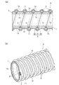
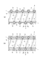
- the tubular body A according to the embodiment of the present invention is used for transporting solids such as granules and powders by a fluid such as compressed air, or for transporting fluids containing the granules and powders, etc. It consists of hoses and tubes used, and has a wear detection function. More specifically, as shown in FIGS. 1 to 6, a tube body A according to an embodiment of the present invention includes a tube body 1 made of a transparent material, and is provided inside the tube body 1 over the entire length of the tube body 1. And a wear detector 2 made of a colored material.
- the transparent material is not limited to a colorless and transparent material, but can be transparent if the wear detector 2 of the colored material provided inside the tube body 1 can be visually confirmed from the outside of the tube body 1. Also included are translucent and colored transparency, which are less transparent.
- the tube body 1 is formed of a flexible synthetic resin such as vinyl chloride resin, a transparent, translucent or colored transparent soft material such as silicone rubber or other rubber, and has a flexible tubular shape, and is located in the vicinity of the inner surface 1a.
- a wear detector 2 described later is embedded away from the outer surface 1b.
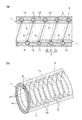
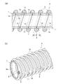
- the structure of the tube body 1 may be a structure in which a plurality of layers are laminated in the radial direction as shown in FIGS. 1 and 2, or may be a single layer structure as shown in FIGS. Good. Further, if necessary, the tube body 1 is partially provided with reinforcing means, so that the entire tube body 1 including the reinforcing means or most of the tube body 1 excluding the reinforcing means can be seen through.
- the reinforcing means includes, for example, a reinforcing wire 3 made of a transparent synthetic resin such as polyester or nylon (registered trademark), a monofilament (monofilament), a multifilament, etc. There is a reinforcing thread (not shown) made of a blade of the above. Further, the reinforcing wire 3 includes those made of an opaque or transparent hard synthetic resin such as vinyl chloride, which is homogeneous with the tube body 1, and those made of a metal wire such as stainless steel.
- the shape of the reinforcing wire 3 it is possible to use various shapes such as a circular cross-section, a cross-sectional ellipse, a substantially rectangular cross-section, a cross-sectionally round shape with a radially outer tip having a circular arc shape, and a substantially trapezoidal cross-section. .
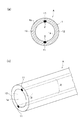
- a circular cross section reinforcement made of a transparent material is provided between the inner layer 1c and the outer layer 1d constituting the tube body 1.
- a part of the outer layer 1d is integrated so as to protrude in a spiral shape.
- the outer layer 1d becomes a smooth surface by embedding a reinforcing wire 3 having a circular cross section made of a transparent resin in a spiral shape between the inner layer 1c and the outer layer 1d. So that they are integrated.
- FIGS. 1A and 1B a circular cross section reinforcement made of a transparent material (transparent resin) is provided between the inner layer 1c and the outer layer 1d constituting the tube body 1.
- the outer surface 1b of the tube body 1 formed in a single layer structure or a laminated structure is formed in a cross-section shape having a circular arc shape with a radially outer tip made of a transparent resin.
- the reinforcing wire 3 having a substantially trapezoidal cross section is integrated by protruding in a spiral shape.
- FIG. 4A and 4B show an example in which the reinforcing wire 3 is not provided on the tube body 1 having a single-layer structure or a laminated structure.
- the tube body 1 is replaced with a structure having three or more layers, the cross-sectional shape of the reinforcing wire 3 made of transparent resin is changed to another shape, or the reinforcing wire 3 made of transparent resin is replaced. It is also possible to change such as providing a reinforcing wire made of a metal wire, or wrapping a plurality of reinforcing threads in a spiral shape regardless of the transparent resin reinforcing wire 3 or the metal reinforcing wire. .
- the wear detection unit 2 is clearly distinguishable from the tube main body 1, for example, is colored in red, blue, yellow, or other colors, and is formed in a linear shape or a belt shape that partially covers a part of the circumferential direction of the tube main body 1. ing.
- a material for the wear detection unit 2 it is preferable to use a material excellent in adhesiveness with the material of the tube main body 1 and the material of the reinforcing wire 3.
- the material of the wear detector 2 when the material of the tube body 1 is a vinyl chloride resin, the polycarbonate system has good adhesion to the vinyl chloride resin and is softer than the reinforcing wire 3 and more wear resistant. It is preferable to mold with a polyurethane resin or the like.
- the other material of the wear detector 2 a material that is non-adhesive with the material of the tube body 1 or the material of the reinforcing wire 3 can be used.
- the shape of the wear detection unit 2 various shapes such as a circular cross section, an elliptical cross section, and a substantially rectangular cross section can be used.
- the wear detection unit 2 is embedded in the pipe body 1 in a spiral or linear shape in the axial direction of the tube main body 1 inside the intermediate position in the thickness direction, and on the pipe main body 1 on the outer side in the thickness direction of the wear detection unit 2. It is possible to see through from the outside of the tube body 1 through the first transparent portion 11 to be arranged.
- the tube body 1 is disposed so that the inside of the tube body 1 can be seen through from the outside of the tube body 1 through the second transparent portion 12 where the wear detection unit 2 is not disposed. Further, the burying position of the wear detecting unit 2 can be arranged inside the reinforcing wire 3 inside the intermediate position in the thickness direction.
- the wear detection unit 2 has an elliptical cross section.
- the wear detector 2 is arranged in a spiral shape along the inside or the outer surface 1b of the tube body 1. 4 (a) and 4 (b), the wear detector 2 is formed in an elliptical cross section, and a plurality of wear detectors 2 are provided in the pipe body 1 in the circumferential direction at predetermined intervals. It is arranged linearly in the axial direction.
- the cross-sectional shape of the wear detector 2 may be replaced with another shape, or replaced with the belt-shaped wear detector 2, or FIGS.
- the spiral wear detector 2 shown in FIGS. 3 (a) and 3 (b) may be replaced with a linear arrangement extending in the axial direction, or a linear wear detector shown in FIGS. 4 (a) and 4 (b). It is also possible to change the part 2 by replacing it with a spiral arrangement.
- the tube body A with the wear detection function a linear shape that partially covers a part of the tube body 1 in the circumferential direction over the entire length of the transparent tube body 1.
- belt-shaped colored wear detection part 2 is embed
- the wear state of the wear detector 2 can be seen through from the outside of the tube body 1 through the first transparent portion 11 disposed outside the wear detector 2 in the tube body 1.
- the inside of the tube main body 1 can be seen through from the outside of the tube main body 1 through the second transparent portion 12 in which the linear or belt-shaped wear detection unit 2 is not disposed in the tube main body 1. Therefore, it is possible to visually confirm both the wear state of the inner surface of the tube (the inner surface 1a of the tube body 1) and the flow state in the tube (the flow state of the transported material flowing in the tube body 1) with a simple structure.
- the tube A can be distinguished easily and at low cost.
- the wear detection portion 2 when the wear detection portion 2 is formed in a linear shape, most of the circumferential direction of the tube body 1 becomes the second transparent portion 12 without the wear detection portion 2, and the area of the second transparent portion 12 is close to the maximum. Enlarged. Therefore, the wear detection unit 2 does not hinder the visual observation, and the flow state of the transported material flowing in the pipe body 1 can be visually confirmed more clearly. As a result, it is possible to more reliably prevent accidents such as clogging of transported goods within the pipe body 1, and further improve safety.
- the wear detector 2 when the wear detector 2 is arranged in a spiral shape with respect to the tube body 1, the wear detector 2 is arranged at equal intervals in the axial direction over the circumferential direction of the inner surface 1 a of the tube body 1. Therefore, it is possible to detect the degree of wear of the entire inner surface 1a of the pipe body 1 in the circumferential direction. As a result, oversight of wear identification can be reduced, and further improvement in safety can be achieved.
- Example 1 As shown in FIGS. 1A, 1B, and 2A, 2B, a reinforcing wire 3 made of a transparent material (transparent resin) is provided on the tube body 1, and the reinforcing wire 3 The wear detection part 2 is embedded inside, and the wear detection part 2 is arranged inside the intermediate position in the thickness direction in the reinforcing wire 3.
- a reinforcing wire 3 made of a transparent material (transparent resin) is provided on the tube body 1, and the reinforcing wire 3
- the wear detection part 2 is embedded inside, and the wear detection part 2 is arranged inside the intermediate position in the thickness direction in the reinforcing wire 3.
- the wear detecting portion 2 is embedded at the inner end position of the reinforcing wire 3, and the reinforcing wire 3 is placed inside the pipe body 1 (between the inner layer 1c and the outer layer 1d).
- the wear detector 2 is disposed in a spiral shape in the inner layer 1c in a state where the wear detection portion 2 has bitten into an intermediate position in the thickness direction.
- the wear detector 2 is embedded at the inner end position of the reinforcing wire 3, and the reinforcing wire 3 is placed inside the pipe body 1 (between the inner layer 1c and the outer layer 1d).
- the wear detector 2 is disposed in a spiral shape in the inner layer 1c in a state where the wear detection portion 2 has bitten into an intermediate position in the thickness direction.
- the wear detecting portion 2 starts to be scraped, and the reinforcing wire
- the wear detector 2 is worn at a point before the entire wear of 3 is finished. Therefore, the wear life can be identified at the timing when the pipe body 1 is reinforced by the reinforcing wire 3.
- the inner surface 1a of the tube body 1 is more difficult to rupture due to wear, and there is an advantage that the safety can be further improved.
- the central portion 31 disposed on the outer side in the thickness direction than the wear detecting portion 2 is arranged in the radial direction.
- the convex lens action through the central part 31 The wear detector 2 appears to expand from the outside. Therefore, even if the size of the colored wear detector 2 is reduced, it can be visually confirmed.
- the wear detector 2 when the wear detector 2 is embedded inside the reinforcing wire 3, if the wear detector 2 is embedded with a large size, the rigidity of the reinforcing wire 3 is adversely affected. There is a possibility that the pressure resistance, shape retention, etc. of the tube A may be lowered. Furthermore, if the size of the wear detection unit 2 is large, the probability that the colored wear detection unit 2 is shaved and mixed into the fluid is higher than that of the wear detection unit 2 having a small size, which adversely affects the quality of the fluid. The possibility is also high. On the other hand, in the case shown in FIGS.
- the wear detecting unit 2 can be thin, so that the reinforcing wire 3 and the pipe There is an advantage that the influence of the wear detection unit 2 on the main body 1 can be minimized and the performance and quality can be prevented from being lowered.
- a reinforcing wire 3 made of a transparent material (transparent resin) is provided on the tube body 1, and the tube body 1 Unlike the first embodiment shown in FIGS. 1 to 3, the configuration in which the wear detecting portion 2 is arranged in the overlapping portion 13 arranged inside the reinforcing wire 3 in the thickness direction is different from the first embodiment shown in FIGS. This is the same as Example 1 shown in FIG.
- FIG. 5 (a) is a modification of that shown in FIGS. 1 (a) and 1 (b), and the wear detector 2 is spirally contacted with the inner end position of the spiral reinforcing wire 3.
- the wear detector 2 is arranged so as to bite into the polymerization site 13 of the inner layer 1c.
- FIG. 5 (b) is a modification of that shown in FIGS. 2 (a) and 2 (b), and the wear detector 2 is spirally contacted with the inner end position of the spiral reinforcing wire 3.
- the wear detector 2 is arranged so as to bite into the polymerization site 13 of the inner layer 1c.
- the wear detection unit 2 is scraped before the wear of the inner surface 1a of the pipe body 1 reaches the reinforcing wire 3. Therefore, the wear life can be identified at the timing when the pipe body 1 is reinforced by the reinforcing wire 3. As a result, it is more difficult to rupture due to wear of the inner surface 1a of the tube body 1 than in the first embodiment, and there is an advantage that further improvement in safety can be achieved.
- the wear detecting portion 2 and the reinforcing wire 3 are respectively arranged in a spiral shape with respect to the pipe body 1, and the wear detecting portion 2 and the reinforcement are provided.
- the configuration in which the relative position of the wire 3 is displaced in the axial direction of the tube body 1 is different from the first embodiment shown in FIGS. 1 to 3 and the second embodiment shown in FIGS. These are the same as the first embodiment shown in FIGS. 1 to 3 and the second embodiment shown in FIGS. Furthermore, in the example shown in FIGS.
- the reinforcing wire 3 is located at a position displaced in the axial direction from the arrangement position of the reinforcing wire 3 in the tube body 1 and in the thickness direction of the tube body 1.
- the wear detection unit 2 is spirally embedded in the soft portion 14 arranged at a level near the inner end position or an inner level thereof.
- the example shown in FIG. 6 (a) is a modification of that shown in FIG. 5 (a), and is a soft portion 14 arranged at a level inside the reinforcing wire 3 in the thickness direction of the inner layer 1c of the tube body 1.
- the helical wear detection part 2 is embedded by being displaced in the axial direction with respect to the embedded position of the reinforcing wire 3.
- the example shown in FIG. 6B is a modification of that shown in FIG. 5B, and is a soft portion 14 arranged at a level inside the reinforcing wire 3 in the thickness direction of the inner layer 1c of the tube body 1.
- the helical wear detection part 2 is embedded by being displaced in the axial direction with respect to the embedded position of the reinforcing wire 3.
- the example shown in FIG. 6C is a modification of that shown in FIGS. 3A and 3B, and the soft portion 14 arranged at the level inside the reinforcing wire 3 in the thickness direction of the tube body 1.
- the helical wear detector 2 is embedded by being displaced in the axial direction with respect to the protruding position of the reinforcing wire 3.
- the embedded position of the wear detecting portion 2 shown in FIGS. 1A, 1B and 2A, 2B is the inner end in the thickness direction of the reinforcing wire 3 in the inner layer 1c. It is also possible to change to a level near the position.
- the tubular body A with the wear detection function according to the third embodiment of the present invention even if the reinforcing wire 3 is made of a colored opaque material, the reinforcing wire 3 is obstructed from the outside of the tube body 1. Instead, the wear state of the wear detector 2 can be seen through the first transparent portion 11 disposed outside the wear detector 2 in the pipe body 1. Therefore, even if the reinforcing wire 3 is opaque, it is possible to visually check the wear state of the inner surface 1a of the tube body 1. As a result, there is also an advantage that the tube A can be distinguished easily and at low cost by changing the color of the reinforcing wire 3.
- the wear detection unit 2 is embedded in the inner layer 1c of the tube body 1 at a level inside the reinforcing wire 3 in the thickness direction, similarly to the second embodiment, the inner surface 1a of the tube body 1 is embedded. At a point before the wear reaches the reinforcing wire 3, the wear detector 2 is shaved. Further, when the burying position of the wear detecting portion 2 is changed to a level near the inner end position in the thickness direction of the reinforcing wire 3 in the inner layer 1c, the wear on the inner surface 1a of the pipe body 1 is reinforced as in the first embodiment.
- the wear detector 2 When reaching the wire 3, the wear detector 2 starts to be worn, and the wear detector 2 is worn before the entire reinforcing wire 3 is completely worn out. Therefore, the wear life can be identified at the timing when the pipe body 1 is reinforced by the reinforcing wire 3. As a result, the inner surface 1a of the tube body 1 is more difficult to rupture due to wear, and there is an advantage that further improvement in safety can be achieved.
- the reinforcing wire 3 made of a transparent material (transparent resin) is provided in a spiral shape on the tube main body 1, but the present invention is not limited to this.
- the reinforcing yarn may be spirally wound and provided in a net shape.
- FIGS. 1A, 1B and 2A, 2B, and in the second embodiment FIGS. 3A, 3B, 5A, and 5B are used.
- the wear detection unit 2 and the reinforcing wire 3 are respectively arranged in a spiral shape.
- the present invention is not limited to this, and as in the example shown in FIGS. 4A and 4B, the wear detection unit 2 and The reinforcing wire 3 may be arranged linearly in the axial direction.
Landscapes
- Engineering & Computer Science (AREA)
- General Engineering & Computer Science (AREA)
- Mechanical Engineering (AREA)
- Rigid Pipes And Flexible Pipes (AREA)
- A Measuring Device Byusing Mechanical Method (AREA)
- Length Measuring Devices With Unspecified Measuring Means (AREA)
Priority Applications (2)
| Application Number | Priority Date | Filing Date | Title |
|---|---|---|---|
| HK16107671.3A HK1219772B (zh) | 2013-09-11 | 2014-08-28 | 管体 |
| CN201480049696.5A CN105518362B (zh) | 2013-09-11 | 2014-08-28 | 管体 |
Applications Claiming Priority (2)
| Application Number | Priority Date | Filing Date | Title |
|---|---|---|---|
| JP2013-188731 | 2013-09-11 | ||
| JP2013188731A JP6161200B2 (ja) | 2013-09-11 | 2013-09-11 | 管体 |
Publications (1)
| Publication Number | Publication Date |
|---|---|
| WO2015037448A1 true WO2015037448A1 (ja) | 2015-03-19 |
Family
ID=52665561
Family Applications (1)
| Application Number | Title | Priority Date | Filing Date |
|---|---|---|---|
| PCT/JP2014/072561 Ceased WO2015037448A1 (ja) | 2013-09-11 | 2014-08-28 | 管体 |
Country Status (4)
| Country | Link |
|---|---|
| JP (1) | JP6161200B2 (enExample) |
| CN (1) | CN105518362B (enExample) |
| MY (1) | MY180217A (enExample) |
| WO (1) | WO2015037448A1 (enExample) |
Cited By (2)
| Publication number | Priority date | Publication date | Assignee | Title |
|---|---|---|---|---|
| JP2018084327A (ja) * | 2016-11-11 | 2018-05-31 | 国立研究開発法人 海上・港湾・航空技術研究所 | 摩耗検知機能をもつ輸送管、摩耗検知方法、及び輸送管の運用方法 |
| EP3385590A1 (de) * | 2017-04-05 | 2018-10-10 | APD Schlauchtechnik GmbH | Wickelschlauch |
Families Citing this family (5)
| Publication number | Priority date | Publication date | Assignee | Title |
|---|---|---|---|---|
| JP6984876B2 (ja) * | 2016-11-11 | 2021-12-22 | 国立研究開発法人 海上・港湾・航空技術研究所 | 摩耗検知機能をもつ輸送管、輸送管の製造方法、摩耗検知方法、及び輸送管の運用方法 |
| JP2020051578A (ja) * | 2018-09-28 | 2020-04-02 | 株式会社クラベ | チューブ |
| CN110953411A (zh) * | 2019-12-13 | 2020-04-03 | 青岛盛高石油装备有限责任公司 | 采矿用耐磨耐高压非金属复合柔性管及其制备方法与应用 |
| JP7553371B2 (ja) | 2021-01-28 | 2024-09-18 | ニッタ化工品株式会社 | ゴムホース及びゴムホースの製造方法 |
| JP7626486B1 (ja) | 2023-07-31 | 2025-02-04 | 株式会社トヨックス | 管体 |
Citations (3)
| Publication number | Priority date | Publication date | Assignee | Title |
|---|---|---|---|---|
| JP2007078008A (ja) * | 2005-09-12 | 2007-03-29 | Toyo Tire & Rubber Co Ltd | 生コンクリート圧送用耐圧ホース |
| JP2010138991A (ja) * | 2008-12-11 | 2010-06-24 | Tigers Polymer Corp | ホースの損傷検知方法、及び耐磨耗性ホース |
| WO2011033796A1 (ja) * | 2009-09-18 | 2011-03-24 | 東拓工業株式会社 | 摩耗検知機能を有する輸送用ホース |
Family Cites Families (2)
| Publication number | Priority date | Publication date | Assignee | Title |
|---|---|---|---|---|
| JPS5347380Y2 (enExample) * | 1975-03-19 | 1978-11-13 | ||
| JP4457610B2 (ja) * | 2003-05-20 | 2010-04-28 | カナフレックスコーポレーション株式会社 | 脱pvc可撓性ホース及びそれの製造方法 |
-
2013
- 2013-09-11 JP JP2013188731A patent/JP6161200B2/ja active Active
-
2014
- 2014-08-28 CN CN201480049696.5A patent/CN105518362B/zh active Active
- 2014-08-28 WO PCT/JP2014/072561 patent/WO2015037448A1/ja not_active Ceased
- 2014-08-28 MY MYPI2016700678A patent/MY180217A/en unknown
Patent Citations (3)
| Publication number | Priority date | Publication date | Assignee | Title |
|---|---|---|---|---|
| JP2007078008A (ja) * | 2005-09-12 | 2007-03-29 | Toyo Tire & Rubber Co Ltd | 生コンクリート圧送用耐圧ホース |
| JP2010138991A (ja) * | 2008-12-11 | 2010-06-24 | Tigers Polymer Corp | ホースの損傷検知方法、及び耐磨耗性ホース |
| WO2011033796A1 (ja) * | 2009-09-18 | 2011-03-24 | 東拓工業株式会社 | 摩耗検知機能を有する輸送用ホース |
Cited By (4)
| Publication number | Priority date | Publication date | Assignee | Title |
|---|---|---|---|---|
| JP2018084327A (ja) * | 2016-11-11 | 2018-05-31 | 国立研究開発法人 海上・港湾・航空技術研究所 | 摩耗検知機能をもつ輸送管、摩耗検知方法、及び輸送管の運用方法 |
| JP7018190B2 (ja) | 2016-11-11 | 2022-02-10 | 国立研究開発法人 海上・港湾・航空技術研究所 | 摩耗検知機能をもつ輸送管、摩耗検知方法、及び輸送管の運用方法 |
| EP3385590A1 (de) * | 2017-04-05 | 2018-10-10 | APD Schlauchtechnik GmbH | Wickelschlauch |
| WO2018185134A1 (de) * | 2017-04-05 | 2018-10-11 | Apd Schlauchtechnik Gmbh | Wickelschlauch |
Also Published As
| Publication number | Publication date |
|---|---|
| JP2015055291A (ja) | 2015-03-23 |
| HK1219772A1 (zh) | 2017-04-13 |
| CN105518362B (zh) | 2017-08-11 |
| CN105518362A (zh) | 2016-04-20 |
| JP6161200B2 (ja) | 2017-07-12 |
| MY180217A (en) | 2020-11-25 |
Similar Documents
| Publication | Publication Date | Title |
|---|---|---|
| JP6161200B2 (ja) | 管体 | |
| JP5413657B2 (ja) | 摩耗検知機能を有する輸送用ホース | |
| AU717810B2 (en) | Hose and method for wear detection | |
| JP4660828B2 (ja) | 摩耗検知機能を有する輸送用ホース | |
| WO2010098849A2 (en) | Leak detecting hose | |
| US20120222765A1 (en) | Flexible hose with wear indicator | |
| US20120222766A1 (en) | Flexible hose with wear indicator | |
| CN101896754A (zh) | 类金属软管 | |
| US20070119363A1 (en) | Hose apparatus wear indicator | |
| JP6757994B1 (ja) | 帯電防止可撓管 | |
| CN103930701A (zh) | 层叠加强软管 | |
| WO2010095569A1 (ja) | 多層耐圧管及びその製造方法 | |
| HK1219772B (zh) | 管体 | |
| JP4775640B2 (ja) | 識別機能を有するホース | |
| JP7626486B1 (ja) | 管体 | |
| JP2007100837A (ja) | 耐圧ホースおよびその製造方法 | |
| JP2008232326A (ja) | 配管ホース | |
| JP2007139174A (ja) | マリンホース | |
| US20160195201A1 (en) | Hose Assembly with Multistage Abrasion Indicator | |
| JP6449049B2 (ja) | ケーブルシース用可撓性ホース | |
| EP2515016B1 (en) | Fluid conveying hose | |
| KR102241023B1 (ko) | 구슬밴드를 포함하는 다층 복합 고무 호스 및 이의 제조 방법 | |
| JP7495024B2 (ja) | 特に化学流体および食品関連流体用の多層管 | |
| WO2025143084A1 (ja) | 輸送用ホース | |
| JP2007078008A (ja) | 生コンクリート圧送用耐圧ホース |
Legal Events
| Date | Code | Title | Description |
|---|---|---|---|
| 121 | Ep: the epo has been informed by wipo that ep was designated in this application |
Ref document number: 14844223 Country of ref document: EP Kind code of ref document: A1 |
|
| NENP | Non-entry into the national phase |
Ref country code: DE |
|
| WWE | Wipo information: entry into national phase |
Ref document number: IDP00201602320 Country of ref document: ID |
|
| 122 | Ep: pct application non-entry in european phase |
Ref document number: 14844223 Country of ref document: EP Kind code of ref document: A1 |