WO2015037447A1 - 切削インサート - Google Patents
切削インサート Download PDFInfo
- Publication number
- WO2015037447A1 WO2015037447A1 PCT/JP2014/072517 JP2014072517W WO2015037447A1 WO 2015037447 A1 WO2015037447 A1 WO 2015037447A1 JP 2014072517 W JP2014072517 W JP 2014072517W WO 2015037447 A1 WO2015037447 A1 WO 2015037447A1
- Authority
- WO
- WIPO (PCT)
- Prior art keywords
- nose
- breaker
- cutting edge
- corner
- cutting
- Prior art date
- Legal status (The legal status is an assumption and is not a legal conclusion. Google has not performed a legal analysis and makes no representation as to the accuracy of the status listed.)
- Ceased
Links
Images






Classifications
-
- B—PERFORMING OPERATIONS; TRANSPORTING
- B23—MACHINE TOOLS; METAL-WORKING NOT OTHERWISE PROVIDED FOR
- B23B—TURNING; BORING
- B23B27/00—Tools for turning or boring machines; Tools of a similar kind in general; Accessories therefor
- B23B27/14—Cutting tools of which the bits or tips or cutting inserts are of special material
- B23B27/141—Specially shaped plate-like cutting inserts, i.e. length greater or equal to width, width greater than or equal to thickness
-
- B—PERFORMING OPERATIONS; TRANSPORTING
- B23—MACHINE TOOLS; METAL-WORKING NOT OTHERWISE PROVIDED FOR
- B23B—TURNING; BORING
- B23B2200/00—Details of cutting inserts
- B23B2200/04—Overall shape
- B23B2200/049—Triangular
-
- B—PERFORMING OPERATIONS; TRANSPORTING
- B23—MACHINE TOOLS; METAL-WORKING NOT OTHERWISE PROVIDED FOR
- B23B—TURNING; BORING
- B23B2200/00—Details of cutting inserts
- B23B2200/08—Rake or top surfaces
- B23B2200/081—Rake or top surfaces with projections
-
- B—PERFORMING OPERATIONS; TRANSPORTING
- B23—MACHINE TOOLS; METAL-WORKING NOT OTHERWISE PROVIDED FOR
- B23B—TURNING; BORING
- B23B2200/00—Details of cutting inserts
- B23B2200/20—Top or side views of the cutting edge
- B23B2200/201—Details of the nose radius and immediately surrounding area
-
- B—PERFORMING OPERATIONS; TRANSPORTING
- B23—MACHINE TOOLS; METAL-WORKING NOT OTHERWISE PROVIDED FOR
- B23B—TURNING; BORING
- B23B2200/00—Details of cutting inserts
- B23B2200/28—Angles
- B23B2200/286—Positive cutting angles
-
- B—PERFORMING OPERATIONS; TRANSPORTING
- B23—MACHINE TOOLS; METAL-WORKING NOT OTHERWISE PROVIDED FOR
- B23B—TURNING; BORING
- B23B2200/00—Details of cutting inserts
- B23B2200/32—Chip breaking or chip evacuation
- B23B2200/321—Chip breaking or chip evacuation by chip breaking projections
Definitions
- This invention relates to a cutting insert that exhibits excellent chip disposal performance in finishing.
- Cutting inserts used for finishing metal are required to have excellent chip disposal performance.
- a chip breaker provided with a chip breaker is used.
- Patent Document 1 is a strip-shaped climbing wall on the rake face of the nose R portion and located near both ends of the nose R portion and extending from the ridge to the boss surface (central land portion). A combination of small protrusions (ridges) is provided.
- a breaker protrusion extending in the direction of a bisector of a corner angle and a first chip breaker groove is provided on a rake face of a nose R portion, and further, a rake angle of the first chip breaker groove is set.
- the rake angle of the second chip breaker groove along the straight cutting edge (side) is sequentially changed within a range smaller than the rake angle of the first chip breaker groove.
- chips are generated because the cutting conditions are low and the feed is low. Therefore, a technique is adopted in which chips are forcibly curled and divided by a chip breaker.
- the conventional cutting inserts disclosed in the above-mentioned Patent Documents 1 to 3 etc. perform cutting of chips mainly depending on breaker protrusions (breaker walls).
- the nose R portion has a constant rake angle, and therefore, the rake face of the nose R portion only provides a simple curling force to the generated chips.
- Chips are likely to collide with the breaker protrusion by curling, but chip breaking with a mechanism that simply curls the chip and collides with the breaker protrusion is the impact force of the chip against the breaker protrusion when the set value of the breaker width is too large. There is not enough to make chips difficult to break.
- Chips discharged without being divided are difficult to control in the outflow direction and are likely to damage the work surface of the work material.
- an object of the present invention is to devise the shape of the chip breaker provided on the rake face so that excellent chip disposal performance can be exhibited in the finishing process.
- the corner cutting edge of the nose R portion the straight cutting edges respectively connected to both ends of the corner cutting edge, the rake face provided along each cutting edge, and the breaker protrusion
- the rake angle in the nose R portion is gradually decreased from the bisected position of the nose R portion toward the end portion of the corner cutting edge, and the breaker width of the nose R portion is 0.5 mm.
- the corner cutting edge of the breaker wall of the breaker projection on the bisector of the corner angle of the nose R section is more than the position where the lines perpendicular to each part of the corner cutting edge gather in one place A cutting insert positioned on the side is provided.
- the bisecting position of the nose R portion means the bisecting position of the corner angle of the nose R portion.
- the terminal part of a corner cutting edge means the boundary part of a corner cutting edge and a linear cutting edge.
- the cutting insert of the present invention configured as described above has improved chip disposal performance as compared with a cutting insert having no change in the rake angle.
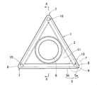
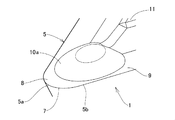
- FIG. 2 is a cross-sectional view taken along line XX of FIG. It is a perspective view of the cutting insert of FIG. It is an enlarged plan view of the nose R part of the cutting insert of FIG. It is an expansion perspective view of the nose R part of the cutting insert of FIG.
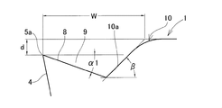
- FIG. 5 is a sectional view taken along line YY in FIG. 4.
- FIG. 5 is a cross-sectional view taken along the line ZZ in FIG. 4.
- FIG. 3 is a diagram showing chips generated by samples I to V in the performance comparison test of Example 1.
- FIG. It is a figure which shows the chip
- FIG. It is a figure which shows the chip
- FIG. It is a figure which shows the chip
- FIG. It is a figure which shows the chip
- FIG. It is a figure which shows the measurement data of the surface roughness of the process surface in the cutting test of Example 6 by sample I- 1 . It is a figure which shows the measurement data of the surface roughness of the processed surface in the cutting test of Example 6 by sample V- 1 .
- FIGS. 1 to 7 of the accompanying drawings The illustrated cutting insert 1 is obtained by applying the present invention to a triangular insert.
- the cutting insert 1 shown in the drawing has an upper surface 2 and a lower surface 3, a side surface 4 along each side of the upper and lower surfaces, and a cutting edge 5 formed by a ridge line at a position where the upper surface 2 and the side surface 4 intersect. Moreover, it has the attachment hole 6 penetrated in the center part of the up-and-down surface.
- the attachment hole 6 is not essential.
- the cutting edge 5 is formed by a ridge line at a position where the upper surface 2 and the side surface 4 serving as a flank face intersect, and the corner cutting edge 5a of the nose R portion and the straight cutting that continues to both ends of the corner cutting edge, respectively. It consists of a blade 5b.
- a region along the corner cutting edge 5 a and the straight cutting edge 5 b on the upper surface 2 is a rake face 8.
- the rake face 8 is given a positive rake angle, and the breaker groove 9 along the cutting edge is created by the positive rake angle.
- a breaker protrusion 10 is provided on the rake face of the nose R portion.
- the breaker protrusion 10 shown in FIG. 4 is a protrusion that forms a semi-ellipse when viewed from the rake face.
- the major axis of the ellipse is arranged so as to be on the bisector of the corner angle of the nose R portion.
- the breaker projection 10 has a breaker wall 10 a rising from the bottom of the breaker groove 9.
- the breaker wall 10a On the bisector of the corner angle of the nose R portion, the breaker wall 10a has a portion where chips flowing out from each part of the corner cutting edge concentrate (from each part of the corner cutting edge 5a) in the machining using only the corner cutting edge 5a.
- the discharged chips flow in a direction perpendicular to each part of the corner cutting edge 5a and are arranged closer to the corner cutting edge 5a than in FIG. 4 (concentrated at a point P where a line perpendicular to each part of the corner cutting edge 5a intersects).
- the breaker wall 10 a is a straight portion rising from the groove bottom of the breaker groove 9.
- the amount d of centering down shown in FIG. 6 of the corner cutting edge 5a is set to 0.20 mm.
- the centering amount d is 0.15 mm or less, the chip breaking property of low cutting and low feeding is poor, and if it is 0.25 mm or more, chip clogging is likely to occur, so the lower limit is 0.15 mm and the upper limit is 0. .25mm is recommended.
- the breaker protrusion 10 shown in the drawing has a portion of the surface of the ellipsoidal sphere removed so that the top of the head is flat.
- the rake angle of the rake face 8 is set such that the rake angle ⁇ 1 (see FIG. 6) in the bisected section of the nose R portion 7 is 20 °, and the rake angle ⁇ 2 (see FIG. 7) of the straight cutting edge 5b is 10 °. ing.
- the rake angle in the heel nose R portion gradually decreases from the bisecting position of the nose R portion 7 toward the end of the nose R portion 7 (the boundary point between the corner cutting edge 5a and the straight cutting edge 5b).
- the term “gradual decrease” as used herein includes a state in which the rake angle is changed stepwise.
- the nose R is usually set to about 0.2 mm to 1.2 mm. In that narrow region, the shape of the rake face whose rake angle has changed stepwise and the shape of the rake face that has changed smoothly are similar, and it is unlikely that a large difference in function will occur.
- the rake angle in the nose R portion 7 is 20 ° at the bisecting position of the nose R portion and 10 ° at the end position of the nose R portion.
- the rake angle ⁇ 1 at the bisecting position of the heel nose R portion 7 is preferably set in a range of 15 ° to 25 °, and for the illustrated tool, the rake angle ⁇ 1 is 20 °. Further, the rake angle ⁇ 2 of the end of the nose R portion 7 and the straight cutting edge portion 5b is preferably in the range of 5 ° to 15 °, and the rake angle ⁇ 2 of the illustrated tool is 10 °.
- the angle difference between the rake angles ⁇ 1 and ⁇ 2 is preferably 5 ° to 10 °.
- the breaker protrusion 10 has an inclination angle ⁇ of the breaker wall 10a of about 25 ° to 50 ° because an effective braking strain is given to chips. That of the illustrated tool is set to 45 °.
- the illustrated tool has a breaker width W of the corner cutting edge 5a (a width to a position where a line extending the breaker wall 10a from the corner cutting edge 5a and a line extending the top surface of the breaker protrusion 10 intersect.
- W of the corner cutting edge 5a a width to a position where a line extending the breaker wall 10a from the corner cutting edge 5a and a line extending the top surface of the breaker protrusion 10 intersect.
- the breaker width W of the R part is suitably 0.5 mm to 0.6 mm.
- the breaker width W was set to 0.5 mm to 0.6 mm.
- the function of the breaker protrusion is not fully demonstrated.
- the chip breaker of the illustrated cutting insert is configured by combining the breaker groove 9 and the breaker protrusion 10.
- the breaker protrusion 10 is formed by cutting the top of the center of the insert toward the corner of the central land portion 11 that is higher than the breaker protrusion 10, but the entire area of the top of the head is at the same height as the central land portion 11. It may be one that has been placed.
- Some conventional cutting inserts have improved cutting performance by applying a complex distortion that increases the apparent thickness of the chip by colliding the chip with a breaker protrusion with a special shape.
- a complex distortion that increases the apparent thickness of the chip by colliding the chip with a breaker protrusion with a special shape.
- the cutting insert of the present invention can increase the apparent chip thickness by changing the rake angle of the corner R portion, and can give a complicated strain that makes the chip easily break.
- Example 1- The effect of the size and angle difference between the rake angle ⁇ 1 at the bisecting position of the nose R portion 7 and the rake angle ⁇ 2 at the end of the nose R portion 7 on the chip disposal performance was examined.
- Table 1 shows the rake angle size and angle difference of the cutting inserts (both materials: cemented carbide) used in the evaluation test.
- Samples I-IV in Table 1 meet the requirements of this invention.
- Sample V is a commercially available cutting insert for finishing.
- Fig. 9 shows the chips produced in this evaluation test together with the sample number. As can be seen from FIG. 9, all the chips generated by the processing using the samples I to IV are finely divided.
- Example 2- The sample I and the sample V (both model number: TPMT110304, material: cermet T1500A) were subjected to a comparison test of chip disposal performance by changing feed and cutting.
- the wrinkle test condition is an inner diameter machining of a work material: S45C, ⁇ 100 mm.
- the cutting speed VC was 200 m / min.
- sample I and the sample V were subjected to a comparative test of chip disposal performance by changing feeding and cutting.
- sample I and sample V both model number: DCMT11T304, material: cermet T1500A
- sample V both model number: DCMT11T304, material: cermet T1500A
- Example 5 The sample I and the sample V (both model number: CPMT090304, material: cermet T1500A) were subjected to a comparative test of chip disposal performance by changing feeding and cutting.
- sample I- 1 having the same specification as the sample I and the sample V- 1 having the same specification as the sample V both are model number: TPMT110304, material: cermet T1500A
- cutting is performed under the following conditions, The roughness was examined.
- 14A and 14B show measurement data of the surface roughness of the processed surface obtained in this test.
- the sample I- 1 is superior in surface roughness of the processed surface compared to the sample V- 1 . This is because the chip is processed better than the sample V- 1 and the processing state is stabilized.
- Sample I- 1 is more glossy than the processed surface of Sample V- 1, and is excellent in surface roughness of the processed surface even by visual inspection.
- the application object of the present invention is not limited to a triangular cutting insert.
- the effects of the invention can be achieved even when applied to other shapes, particularly diamond-shaped or parallelogram-shaped cutting inserts having a nose radius portion of an acute corner.
Landscapes
- Engineering & Computer Science (AREA)
- Mechanical Engineering (AREA)
- Cutting Tools, Boring Holders, And Turrets (AREA)
Abstract
ノーズR部のコーナ切れ刃と、そのコーナ切れ刃の両端にそれぞれ連なる直線切れ刃と、各切れ刃に沿って設けられる正のすくい角を有するすくい面と、ブレーカ突起を具備した切削インサートであって、前記ノーズR部におけるすくい角を、このノーズR部の2等分位置からノーズR部の終端に向って徐々に減少させ、さらに、ノーズR部におけるブレーカ幅を0.5mm~0.6mmに設定し、ノーズR部のコーナ角の2等分線上において前記ブレーカ突起のブレーカ壁を、前記コーナ切れ刃の各部に直交する線が1箇所に集合する位置よりもコーナ切れ刃側に位置させた切削インサート。
Description
この発明は、仕上げ加工において優れた切屑処理性能を発揮する切削インサートに関する。
金属の仕上げ加工に利用される切削インサートは、切屑処理性能に優れていることが要求される。そのために、すくい面にチップブレーカを設けたものが利用されている。
そのチップブレーカとして、例えば、下記特許文献1は、ノーズR部のすくい面上に登り傾斜のブレーカ壁とノーズR部の両端近くに位置して稜からボス面(中央ランド部)に向かう帯状の小突起(リッジ)を組み合わせたものを設けている。
また、下記特許文献2は、ノーズR部のすくい面上に第1のチップブレーカ溝とコーナ角の2等分線方向に延びるブレーカ突起を設け、さらに、第1のチップブレーカ溝のすくい角を0°~30°の範囲に設定し、直線切れ刃(辺)に沿った第2のチップブレーカ溝のすくい角を第1のチップブレーカ溝のすくい角よりも小さな範囲で順次変化させている。
このほか、下記特許文献3のように、ノーズR部のすくい面上に高さが2段に変化したブレーカ壁を設けたものなども知られている。
仕上げ加工は、切削条件が低切り込み、低送りとなることから生成される切屑が薄くなる。そこで、チップブレーカによって切屑を強制的にカールさせ、分断させる手法が採られている。
ところが、一般的なチップブレーカによる切屑処理では、切屑がブレーカ壁に接触しても分断され難い。その傾向は、軟鋼や一般鋼のように折れ難い金属の加工では特に高まる。
前掲の特許文献1~3などに開示された従来の切削インサートは、切屑の分断を主にブレーカ突起(ブレーカ壁)に依存して行っている。ノーズR部はすくい角を一定させており、そのために、ノーズR部のすくい面からは生成された切屑に単純な形でカールする力が付与されるに過ぎない。
切屑はカールすることでブレーカ突起に衝突し易くなるが、切屑を単純にカールさせてブレーカ突起に衝突させるメカニズムでの切屑分断は、ブレーカ幅の設定値が大き過ぎるとブレーカ突起に対する切屑の衝突力が不足して切屑が折れ難くなる。
分断されずに排出される切屑は流出方向の制御が難しく、被削材の加工面を傷つける可能性が高い。
また、ブレーカ幅の設定値が小さ過ぎると切屑詰まりが発生して加工の安定性が損なわれ、被削材の加工面の面性状なども悪化する。
そこで、この発明は、すくい面に設けるチップブレーカの形状を工夫して仕上げ加工において優れた切屑処理性能が発揮されるようにすることを課題としている。
上記の課題を解決するため、この発明においては、ノーズR部のコーナ切れ刃と、そのコーナ切れ刃の両端にそれぞれ連なる直線切れ刃と、各切れ刃に沿って設けられるすくい面と、ブレーカ突起を具備し、前記ノーズR部おけるすくい角を、このノーズR部の2等分位置から前記コーナ切れ刃の終端部に向って徐々に減少させ、さらに、ノーズR部のブレーカ幅を0.5mm~0.6mmに設定し、ノーズR部のコーナ角の2等分線上において前記ブレーカ突起のブレーカ壁を、前記コーナ切れ刃の各部に直交する線が1箇所に集合する位置よりもコーナ切れ刃側に位置させた切削インサートを提供する。
なお、ノーズR部の2等分位置とは、ノーズR部のコーナ角の2等分位置を言う。また、コーナ切れ刃の終端部とは、コーナ切れ刃と直線切れ刃の境界部を言う。
上記のように構成したこの発明の切削インサートは、すくい角の変化のない切削インサートに比べて切屑処理性能が向上する。
以下、添付図面の図1~図7に基づいて、この発明の切削インサートの実施の形態を説明する。例示の切削インサート1は、三角形のインサートにこの発明を適用したものである。
図示の切削インサート1は、上面2及び下面3と、上下面の各辺に沿った側面4と、上面2と側面4が交差した位置の稜線によって形成される切れ刃5を有する。また、上下面の中央部に貫通した取付け孔6を有する。取付け孔6は必須ではない。
7は、隣り合う2側面間のコーナに作り出されたノーズR部である。切れ刃5は、上面2と逃げ面となる側面4が交わった位置の稜線によって形成されるものであって、ノーズR部のコーナ切れ刃5aと、そのコーナ切れ刃の両端にそれぞれ連なる直線切れ刃5bとからなる。
上面2のコーナ切れ刃5aと直線切れ刃5bに沿った領域は、すくい面8となっている。そのすくい面8には、正のすくい角を付与しており、その正のすくい角の付与によって切れ刃に沿ったブレーカ溝9が作り出されている。
また、ノーズR部のすくい面上には、ブレーカ突起10が設けられている。図4に示すブレーカ突起10は、すくい面から見て半楕円をなす突起である。その楕円の長軸がノーズR部のコーナ角の2等分線上にあるように配置されている。
そのブレーカ突起10は、ブレーカ溝9の溝底から立ち上がるブレーカ壁10aを有している。ノーズR部のコーナ角の2等分線上においてブレーカ壁10aは、コーナ切れ刃5aのみを使用する加工において、そのコーナ切れ刃の各部から流出する切屑が集中する箇所(コーナ切れ刃5aの各部から排出される切屑は、コーナ切れ刃5aの各部に直交する方向に流れ、図4においてコーナ切れ刃5aの各部に直交した線が交わるP点に集中する)よりもコーナ切れ刃5a側に配置されている。図6においてブレーカ壁10aはブレーカ溝9の溝底から立ち上がる直線部分である。
このほかに、コーナ切れ刃5aの図6に示した芯下り量dが0.20mmにされている。この芯下がりの設定により、切屑がブレーカ突起10に衝突し易くなる。この芯下り量dは、0.15mm以下では、低切り込み、低送り出の切屑分断性が悪く、また、0.25mm以上では切屑詰まりが発生し易くなるので下限を0.15mm、上限を0.25mmにするのがよい。
なお、図示のブレーカ突起10は、楕円球の表面の一部が除去されて頭頂部が平担になっている。
すくい面8のすくい角は、ノーズR部7の2等分断面におけるすくい角α1(図6参照)が20°、直線切れ刃5bのすくい角α2(図7参照)が10°にそれぞれ設定されている。
ノーズR部内のすくい角は、ノーズR部7の2等分位置からノーズR部7の終端(コーナ切れ刃5aと直線切れ刃5bの境界点)に向って徐々に減少している。
ここで言う「徐々に減少」は、すくい角が階段状に変化した状態も含む。ノーズRは、通常、0.2mm~1.2mm程度に設定される。その狭い領域の中では、すくい角が階段状に変化したすくい面と滑らかに変化したすくい面の形状は似たものになり、機能に大きな差が生じることは考え難い。
例示の切削インサートについては、ノーズR部7内のすくい角は、ノーズR部の2等分位置で20°、ノーズR部の終端位置で10°となっている。
ノーズR部7の2等分位置のすくい角α1は15°~25°の範囲に設定するのがよく、図示の工具については、そのすくい角α1が20°となっている。また、ノーズR部7の終端と直線切れ刃部5bのすくい角α2は5°~15°の範囲がよく、図示の工具についてはそのすくい角α2が10°になっている。
すくい角α1とα2の角度差は、5°~10°が好ましい。
ブレーカ突起10は、ブレーカ壁10aの傾斜角βが25°~50°程度であるのが切屑に対して効果的なブレーキング歪を与えられて好ましい。図示の工具のそれは45°に設定されている。
また、図示の工具は、コーナ切れ刃5aのブレーカ幅W(コーナ切れ刃5aからブレーカ壁10aを延長した線とブレーカ突起10の頭頂面を延長した線が交差する位置までの幅。図6参照)が0.6mmに設定されている。
切込みap=0.1mm~0.8mm、送りf=0.03mm/rev~0.20mm/revの加工条件で使用するとして、切屑詰まりの防止と良好な分断性能の両立を考えた場合、ノーズR部のブレーカ幅Wは、0.5mm~0.6mmが適当であった。
このブレーカ幅Wは、0.5mm以下に設定することも行われているが、切削速度VC=100m/min以上、送りf=0.05mm/rev~0.20mm/revと言った条件での切削では切屑詰まりが起こる。
そこで、ブレーカ幅Wを0.5mm~0.6mmに設定することを検討したが、送りf=0.10mm/rev~0.20mm/revと言った条件での加工ではブレーカ幅が広過ぎてブレーカ突起の機能が十分に発揮されない。
その状況でも、ブレーカ溝に対する分断の依存度を高めることで切屑を良好に処理し得ることを見出してこの発明を完成させるに至った。
なお、例示の切削インサートのチップブレーカは、ブレーカ溝9とブレーカ突起10を組み合わせて構成されている。ブレーカ突起10は、インサート中央側の頭頂部をブレーカ突起10よりも位置の高い中央ランド部11のコーナに向けて切り上がらせているが、頭頂部の全域が中央ランド部11と同一高さ位置におかれたものであってもよい。
このように構成した実施形態の切削インサートは、ノーズR部7内においてすくい角を変化させたことによって、生成される切屑が正面視において凹形状に湾曲し、見かけ上の切屑厚みが大きくなる。
また、すくい角の変化により見かけ上の切屑厚みが増加した切屑に対して複雑な歪が加わり、その切屑がブレーカ壁に衝突することで折れ易くなって分断性能が向上し、切屑処理が良好になされる。
切削インサートの従来品の中には、形状の工夫されたブレーカ突起に切屑を衝突させることでその切屑に見かけ上の厚みが大きくなるような複雑な歪を付与して分断性を高めたものがあるが、切屑詰まり防止の観点からブレーカ幅を上記値のように大きくしたものは、ブレーカ突起によって切屑に複雑な歪を付与するのは難しい。
この発明の切削インサートは、コーナR部のすくい角を変化させることで、見かけ上の切屑厚みを増加させ、切屑が折れ易くなる複雑な歪を付与することが可能になっている。
-実施例1-
ノーズR部7の2等分位置のすくい角α1とノーズR部7の終端のすくい角α2の大きさと角度差が切屑処理性能に及ぼす影響を調べた。その評価試験に用いた切削インサート(いずれも材質:超硬合金)のすくい角の大きさと角度差を表1に示す。
ノーズR部7の2等分位置のすくい角α1とノーズR部7の終端のすくい角α2の大きさと角度差が切屑処理性能に及ぼす影響を調べた。その評価試験に用いた切削インサート(いずれも材質:超硬合金)のすくい角の大きさと角度差を表1に示す。

表1の試料I~IVはこの発明の要件を満たす。試料Vは市販されている仕上げ用切削インサートである。
試料Vのチップブレーカ形状を図8に示す。
これらの試料I~Vの切屑処理性能の評価は、被削材:S45Cの内径加工を実施して行った。加工孔の内径はφ100mm、切削条件は、切削速度VC=200m/min、送りf=0.10mm/rev、切込みap=0.2mmである。
この評価試験で生成された切屑を試料番号とともに図9に示す。この図9からわかるように、試料I~IVによる加工で生成された切屑はいずれも細かく分断されている。
これに対し、試料Vによる加工で生成された切屑は、比較的長いものが見られる。
-実施例2-
前記試料Iと試料V(両者とも型番:TPMT110304、材質:サーメットT1500A)について送りと切込みを変えて切屑処理性能の比較試験を行った。
前記試料Iと試料V(両者とも型番:TPMT110304、材質:サーメットT1500A)について送りと切込みを変えて切屑処理性能の比較試験を行った。
試験条件は、被削材:S45C,φ100mmの内径加工である。切削速度VC=200m/minとした。
この試験で生成された切屑を図10に示す。この図10から、試料Iは、特に送りf=0.05mm/rev~0.10mm/rev、切込みap=0.1mm~0.2mmの組み合わせにおいて試料Vに比べて切屑処理性に勝ることがわかる。
-実施例3-
前記試料Iと試料V(両者とも型番:TPMT110308、材質:サーメットT1500A)について送りと切込みを変えて切屑処理性能の比較試験を行った。
前記試料Iと試料V(両者とも型番:TPMT110308、材質:サーメットT1500A)について送りと切込みを変えて切屑処理性能の比較試験を行った。
被削材:S45C,φ30mmの外径加工である。切削速度VC=200m/minとした。
この試験で生成された切屑を図11に示す。この図11から、試料Iは、送りf=0.08mm/rev~0.12mm/rev、切込みap=0.2mm~0.3mmの組み合わせにおいて試料Vに比べて切屑処理性に勝ることがわかる。
-実施例4-
前記試料Iと試料V(両者とも型番:DCMT11T304、材質:サーメットT1500A)について送りと切込みを変えて切屑処理性能の比較試験を行った。
前記試料Iと試料V(両者とも型番:DCMT11T304、材質:サーメットT1500A)について送りと切込みを変えて切屑処理性能の比較試験を行った。
被削材:S45C,φ30mmの外径加工である。切削速度VC=200m/minとした。
この試験で生成された切屑を図12に示す。この図12から、試料Iは、送りf=0.08mm/rev~0.12mm/rev、切込みap=0.2mm~0.3mmの組み合わせにおいて試料Vに比べて切屑処理性に勝ることがわかる。
-実施例5-
前記試料Iと試料V(両者とも型番:CPMT090304、材質:サーメットT1500A)について送りと切込みを変えて切屑処理性能の比較試験を行った。
前記試料Iと試料V(両者とも型番:CPMT090304、材質:サーメットT1500A)について送りと切込みを変えて切屑処理性能の比較試験を行った。
被削材:S45C,φ30mmの外径加工である。切削速度VC=200m/minとした。
この試験で生成された切屑を図12に示す。この図12から、試料Iは、送りf=0.08mm/rev~0.12mm/rev、切込みap=0.2mm~0.3mmの組み合わせにおいて試料Vに比べて切屑処理性に勝ることがわかる。
-実施例6-
前記試料Iと同一仕様の試料I-1と前記試料V同一仕様の試料V-1(両者とも型番:TPMT110304、材質:サーメットT1500A)を用いて下記の条件で切削加工を行い、加工面の面粗さを調べた。
前記試料Iと同一仕様の試料I-1と前記試料V同一仕様の試料V-1(両者とも型番:TPMT110304、材質:サーメットT1500A)を用いて下記の条件で切削加工を行い、加工面の面粗さを調べた。
-切削条件-
被削材:SCM415、外径φ80mmの棒材。外径加工。切削速度VC=100m/min、送りf=0.10mm/rev、切込みap=0.2mm。
被削材:SCM415、外径φ80mmの棒材。外径加工。切削速度VC=100m/min、送りf=0.10mm/rev、切込みap=0.2mm。
この試験で得られた加工面の面粗さの測定データを図14A,図14Bに示す。この測定データから判るように、試料I-1は、試料V-1に比べて加工面の面粗さに優れる。
これは、切屑の処理が試料V-1よりも良好になされて加工状態が安定したからにほかならない。
これは、切屑の処理が試料V-1よりも良好になされて加工状態が安定したからにほかならない。
試料I-1は、試料V-1による加工面よりも光沢に優れ、目視検査でも加工面の面粗さに優れることがわかる。
なお、この発明の適用対象は、三角形の切削インサートに限定されない。他の形状、特に鋭角コーナのノーズR部を有する菱形や平行四辺形の切削インサートなどに適用しても発明の効果が発揮される。
1 切削インサート
2 上面
3 下面
4 側面
5 切れ刃
5a コーナ切れ刃
5b 直線切れ刃
6 取付け孔
7 ノーズR部
8 すくい面
9 ブレーカ溝
10 ブレーカ突起
10a ブレーカ壁
11 中央ランド部
α1 ノーズR部の2等分断面におけるすくい角
α2 直線切れ刃部のすくい角
P 切屑が集中する箇所
I~V,I-1,V-1 試料
2 上面
3 下面
4 側面
5 切れ刃
5a コーナ切れ刃
5b 直線切れ刃
6 取付け孔
7 ノーズR部
8 すくい面
9 ブレーカ溝
10 ブレーカ突起
10a ブレーカ壁
11 中央ランド部
α1 ノーズR部の2等分断面におけるすくい角
α2 直線切れ刃部のすくい角
P 切屑が集中する箇所
I~V,I-1,V-1 試料
Claims (4)
- ノーズR部のコーナ切れ刃と、そのコーナ切れ刃の両端にそれぞれ連なる直線切れ刃と、各切れ刃に沿って設けられる正のすくい角を有するすくい面と、ブレーカ突起を具備した切削インサートであって、前記ノーズR部におけるすくい角を、このノーズR部の2等分位置からノーズR部の終端に向って徐々に減少させ、さらに、ノーズR部におけるブレーカ幅を0.5mm~0.6mmに設定し、ノーズR部のコーナ角の2等分線上において前記ブレーカ突起のブレーカ壁を、前記コーナ切れ刃の各部に直交する線が1箇所に集合する位置よりもコーナ切れ刃側に位置させた切削インサート。
- 前記ノーズR部の2等分位置のすくい角を15°~25°の範囲に、前記コーナ切れ刃の終端のすくい角を5°~15°の範囲にそれぞれ設定し、さらに、前記ノーズR部の2等分位置のすくい角と前記コーナ切れ刃の終端のすくい角の角度差を5°~10°に設定した請求項1に記載の切削インサート。
- 前記ブレーカ壁の傾斜角を25°~50°に設定した請求項1又は請求項2に記載の切削インサート。
- 前記コーナ切れ刃を芯下がりの切れ刃にした請求項1~請求項3のいずれか1つに記載の切削インサート。
Applications Claiming Priority (2)
| Application Number | Priority Date | Filing Date | Title |
|---|---|---|---|
| JP2013-189356 | 2013-09-12 | ||
| JP2013189356A JP2015054371A (ja) | 2013-09-12 | 2013-09-12 | 切削インサート |
Publications (1)
| Publication Number | Publication Date |
|---|---|
| WO2015037447A1 true WO2015037447A1 (ja) | 2015-03-19 |
Family
ID=52665560
Family Applications (1)
| Application Number | Title | Priority Date | Filing Date |
|---|---|---|---|
| PCT/JP2014/072517 Ceased WO2015037447A1 (ja) | 2013-09-12 | 2014-08-28 | 切削インサート |
Country Status (2)
| Country | Link |
|---|---|
| JP (1) | JP2015054371A (ja) |
| WO (1) | WO2015037447A1 (ja) |
Cited By (2)
| Publication number | Priority date | Publication date | Assignee | Title |
|---|---|---|---|---|
| CN114951725A (zh) * | 2022-05-16 | 2022-08-30 | 株洲肯特硬质合金股份有限公司 | 一种可转位车削刀片 |
| CN115673359A (zh) * | 2021-07-27 | 2023-02-03 | 长合工业技术(天津)有限公司 | 一种多应用切削刀片及刀具 |
Families Citing this family (1)
| Publication number | Priority date | Publication date | Assignee | Title |
|---|---|---|---|---|
| TWI670127B (zh) * | 2019-01-30 | 2019-09-01 | 張新添 | 捨棄式刀片鎖固結構 |
Citations (5)
| Publication number | Priority date | Publication date | Assignee | Title |
|---|---|---|---|---|
| JPH10217008A (ja) * | 1997-01-31 | 1998-08-18 | Kyocera Corp | 切削インサート |
| JP2000107911A (ja) * | 1998-10-05 | 2000-04-18 | Mitsubishi Materials Corp | スローアウェイチップ |
| EP1852200A2 (de) * | 2006-05-03 | 2007-11-07 | CERATIZIT Austria Gesellschaft m.b.H. | Schneideinsatz zur spanabhebenden Bearbeitung |
| JP2008000837A (ja) * | 2006-06-21 | 2008-01-10 | Tungaloy Corp | スローアウェイチップ |
| JP2013067004A (ja) * | 2011-09-23 | 2013-04-18 | Sandvik Intellectual Property Ab | 多角形旋削インサート |
-
2013
- 2013-09-12 JP JP2013189356A patent/JP2015054371A/ja active Pending
-
2014
- 2014-08-28 WO PCT/JP2014/072517 patent/WO2015037447A1/ja not_active Ceased
Patent Citations (5)
| Publication number | Priority date | Publication date | Assignee | Title |
|---|---|---|---|---|
| JPH10217008A (ja) * | 1997-01-31 | 1998-08-18 | Kyocera Corp | 切削インサート |
| JP2000107911A (ja) * | 1998-10-05 | 2000-04-18 | Mitsubishi Materials Corp | スローアウェイチップ |
| EP1852200A2 (de) * | 2006-05-03 | 2007-11-07 | CERATIZIT Austria Gesellschaft m.b.H. | Schneideinsatz zur spanabhebenden Bearbeitung |
| JP2008000837A (ja) * | 2006-06-21 | 2008-01-10 | Tungaloy Corp | スローアウェイチップ |
| JP2013067004A (ja) * | 2011-09-23 | 2013-04-18 | Sandvik Intellectual Property Ab | 多角形旋削インサート |
Cited By (2)
| Publication number | Priority date | Publication date | Assignee | Title |
|---|---|---|---|---|
| CN115673359A (zh) * | 2021-07-27 | 2023-02-03 | 长合工业技术(天津)有限公司 | 一种多应用切削刀片及刀具 |
| CN114951725A (zh) * | 2022-05-16 | 2022-08-30 | 株洲肯特硬质合金股份有限公司 | 一种可转位车削刀片 |
Also Published As
| Publication number | Publication date |
|---|---|
| JP2015054371A (ja) | 2015-03-23 |
Similar Documents
| Publication | Publication Date | Title |
|---|---|---|
| JP5187447B2 (ja) | 切削インサートおよび切削工具 | |
| JP5024483B2 (ja) | 切削インサート | |
| JP6356781B2 (ja) | 切削インサート、切削工具及び切削加工物の製造方法 | |
| JP5895456B2 (ja) | 切削インサート | |
| CN101745675B (zh) | 双面的可转位面铣刀片 | |
| CN103008697B (zh) | 多边形车削刀片 | |
| JP5888656B2 (ja) | 切削インサートとフライスカッタ | |
| CN105980089B (zh) | 切削镶刀、切削工具以及切削加工物的制造方法 | |
| CN105517737B (zh) | 切削刀具 | |
| JP6005838B2 (ja) | 切削インサート、切削工具および切削加工物の製造方法 | |
| US9375791B2 (en) | Polygonal turning insert | |
| JP6459077B2 (ja) | 切削インサート | |
| CN109843484B (zh) | 车削刀片 | |
| JPH10502303A (ja) | カッティングインサート | |
| CN105531055B (zh) | 切削镶刀、切削工具以及切削加工物的制造方法 | |
| TWI754082B (zh) | 具有切屑形成配置的負精車削嵌件 | |
| WO2015037447A1 (ja) | 切削インサート | |
| JP2005288613A (ja) | スローアウェイチップ | |
| JP2012045634A (ja) | 切削インサート | |
| CN107812994B (zh) | 一种用于侧面或端面铣削的可转位刀片 | |
| JP2007260841A (ja) | 切削インサート | |
| JP2000246516A (ja) | 切削インサート | |
| JP2000280107A (ja) | 切削インサート | |
| JP4869283B2 (ja) | スローアウェイエンドミル及びそれに用いるスローアウェイエンドミル用チップ | |
| JPH11197909A (ja) | スローアウェイチップ |
Legal Events
| Date | Code | Title | Description |
|---|---|---|---|
| 121 | Ep: the epo has been informed by wipo that ep was designated in this application |
Ref document number: 14843540 Country of ref document: EP Kind code of ref document: A1 |
|
| NENP | Non-entry into the national phase |
Ref country code: DE |
|
| 122 | Ep: pct application non-entry in european phase |
Ref document number: 14843540 Country of ref document: EP Kind code of ref document: A1 |