WO2015037427A1 - 浴槽 - Google Patents
浴槽 Download PDFInfo
- Publication number
- WO2015037427A1 WO2015037427A1 PCT/JP2014/072180 JP2014072180W WO2015037427A1 WO 2015037427 A1 WO2015037427 A1 WO 2015037427A1 JP 2014072180 W JP2014072180 W JP 2014072180W WO 2015037427 A1 WO2015037427 A1 WO 2015037427A1
- Authority
- WO
- WIPO (PCT)
- Prior art keywords
- bathtub
- hole
- surface portion
- hot water
- portions
- Prior art date
- Legal status (The legal status is an assumption and is not a legal conclusion. Google has not performed a legal analysis and makes no representation as to the accuracy of the status listed.)
- Ceased
Links
Images

Classifications
-
- A—HUMAN NECESSITIES
- A47—FURNITURE; DOMESTIC ARTICLES OR APPLIANCES; COFFEE MILLS; SPICE MILLS; SUCTION CLEANERS IN GENERAL
- A47K—SANITARY EQUIPMENT; ACCESSORIES THEREFOR, e.g. TOILET ACCESSORIES
- A47K3/00—Baths; Showers; Appurtenances therefor
- A47K3/02—Baths
-
- A—HUMAN NECESSITIES
- A61—MEDICAL OR VETERINARY SCIENCE; HYGIENE
- A61H—PHYSICAL THERAPY APPARATUS, e.g. DEVICES FOR LOCATING OR STIMULATING REFLEX POINTS IN THE BODY; ARTIFICIAL RESPIRATION; MASSAGE; BATHING DEVICES FOR SPECIAL THERAPEUTIC OR HYGIENIC PURPOSES OR SPECIFIC PARTS OF THE BODY
- A61H33/00—Bathing devices for special therapeutic or hygienic purposes
- A61H33/02—Bathing devices for use with gas-containing liquid, or liquid in which gas is led or generated, e.g. carbon dioxide baths
-
- A—HUMAN NECESSITIES
- A47—FURNITURE; DOMESTIC ARTICLES OR APPLIANCES; COFFEE MILLS; SPICE MILLS; SUCTION CLEANERS IN GENERAL
- A47K—SANITARY EQUIPMENT; ACCESSORIES THEREFOR, e.g. TOILET ACCESSORIES
- A47K3/00—Baths; Showers; Appurtenances therefor
- A47K3/12—Separate seats or body supports
-
- A—HUMAN NECESSITIES
- A61—MEDICAL OR VETERINARY SCIENCE; HYGIENE
- A61H—PHYSICAL THERAPY APPARATUS, e.g. DEVICES FOR LOCATING OR STIMULATING REFLEX POINTS IN THE BODY; ARTIFICIAL RESPIRATION; MASSAGE; BATHING DEVICES FOR SPECIAL THERAPEUTIC OR HYGIENIC PURPOSES OR SPECIFIC PARTS OF THE BODY
- A61H2201/00—Characteristics of apparatus not provided for in the preceding codes
- A61H2201/01—Constructive details
- A61H2201/0107—Constructive details modular
-
- A—HUMAN NECESSITIES
- A61—MEDICAL OR VETERINARY SCIENCE; HYGIENE
- A61H—PHYSICAL THERAPY APPARATUS, e.g. DEVICES FOR LOCATING OR STIMULATING REFLEX POINTS IN THE BODY; ARTIFICIAL RESPIRATION; MASSAGE; BATHING DEVICES FOR SPECIAL THERAPEUTIC OR HYGIENIC PURPOSES OR SPECIFIC PARTS OF THE BODY
- A61H2201/00—Characteristics of apparatus not provided for in the preceding codes
- A61H2201/16—Physical interface with patient
- A61H2201/1602—Physical interface with patient kind of interface, e.g. head rest, knee support or lumbar support
- A61H2201/1628—Pelvis
- A61H2201/1633—Seat
Definitions
- the present invention relates to a bathtub.
- Patent Document 1 discloses a conventional bathtub.
- This bathtub includes a bottom surface portion and a side surface portion that rises upward from the bottom surface portion, and forms a hot water storage portion that stores hot water by the bottom surface portion and the side surface portion.
- this bathtub is provided with a headrest which is a member for a bathtub attached to the inner surface of the side surface portion facing the hot water storage portion side.
- the headrest has a pair of convex portions.
- the bathtub is provided with two pairs of holes corresponding to the convex portions of the headrest on the side surface.
- the headrest is attached to the inner side surface of the side surface portion of the bathtub by selecting one of the two sets of hole portions provided in the side surface portion of the bathtub and inserting a convex portion into the selected pair of hole portions.
- this bathtub can change the attachment position of a headrest by selecting either of two sets of hole parts provided in the side part.
- Patent Document 1 has two sets of holes on the side surface below the highest hot water storage level. For this reason, hot water penetrates into each hole, and it takes time to drain the hot water that has entered. Therefore, there is a risk that water will accumulate in each hole, or water may leak depending on the state of the hole.
- the present invention has been made in view of the above-described conventional situation, and it is an object to be solved to provide a bathtub in which dirt and water leakage can be prevented and a bathtub member can be favorably attached.
- the bathtub of the present invention includes a bottom part, a side part rising upward from the bottom part, and a bathtub member attached to the inner side faced to the hot water storage part formed by the side part and the bottom part.
- a bathtub with A part of the side surface portion extends upward from the maximum hot water storage level, and the side surface portion includes an extending portion provided with a hole portion in which a part of the bathtub member is locked or inserted. .
- This bathtub may lock a part of the bathtub member using a hole provided in the extending part extending upward from the maximum hot water storage level or insert a part of the bathtub member. it can. Since the hole is provided above the maximum hot water storage water level, the hot water stored in the bathtub does not enter the hole. Therefore, it is possible to prevent water from accumulating in the hole or leaking from the hole.
- the bathtub of the present invention can prevent dirt and water leakage and can favorably attach the bathtub member.
- the bathtub member can be detachably attached to the inner surface of the extending portion. In this case, the bathtub member can be easily replaced. For this reason, this bathtub can attach the member for bathtubs from which a function and a shape differ. Moreover, the member for bathtubs can be easily removed in order to perform maintenance or the like.
- the hole may be covered with the bathtub member when the bathtub member is attached to the inner surface.
- the design of the bathtub can be improved.
- water leakage can be reliably prevented from the hole by, for example, bringing the bathtub member into close contact with the periphery of the hole.
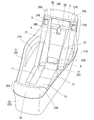
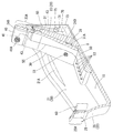
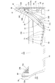
- the bathtub of the embodiment includes a bottom surface portion 10, a side surface portion 20, and bathtub members 30, 40, 50, and 60.
- the bottom surface portion 10 has a substantially rectangular shape when viewed from above.
- the bather takes a bathing posture (posted seat while throwing his feet forward)
- one of the short sides of the bottom surface portion 10 is on the back side and the other short side portion is on the foot side.
- the bottom surface portion 10 is formed to be slightly wider toward the back side when the bather takes a bathing posture in the bathtub.
- the side surface portion 20 rises upward from the outer peripheral edge of the bottom surface portion 10.
- the side part 20 is composed of a left and right side part 21, a back side part 23, and a foot side part 25.
- the left and right side surface portions 21 rise from the outer edges of the long side portions on both sides of the bottom surface portion 10.
- the side where the upper body of the bather is located swells to the left and right when the bather takes a bathing posture in the bathtub.
- the left and right side surface portions 21 are provided with armrest portions 21A on the inner surface of the portion that swells to the left and right.
- the back side surface portion 23 rises obliquely outward and upward from one outer edge of the short side portion of the bottom surface portion 10.
- the back side surface portion 23 is provided with a backrest member 30 on which the bather's back rests when the bather takes a bathing posture in the bath.
- the back side surface portion 23 extends upward from the upper end edges of the left and right side surface portions 21. That is, the back side surface portion 23 includes an extending portion 23 ⁇ / b> A that extends upward from the maximum hot water storage level (height equal to the upper end edge of the left and right side surface portions 21).
- the back side surface portion 23 is provided with four holes in the extending portion 23 ⁇ / b> A and one hole in the vicinity of the bottom surface portion 10.
- the two locking hole portions 24A are the inner side surface of the extending portion 23A and open to the front in a rectangular shape that is long in the vertical direction on each of the left and right ends.
- the remaining one locking hole portion 24B is an inner surface of the extending portion 23A and is open in the longitudinally long rectangular shape in the left and right central portion and facing forward, and above the locking hole portion 24B. The opening is directed upward so as to communicate with the lateral groove 26 extending in the left-right direction.
- the three locking hole portions 24A and 24B are formed with a groove portion X inserted into and locked by a flange portion 31A of the locking portion 31 of the backrest member 30 described later on the back side of the bottom side portion. Further, these three locking hole portions 24 ⁇ / b> A and 24 ⁇ / b> B do not penetrate the extending portion 23 ⁇ / b> A of the back side surface portion 23.
- the remaining one-hole portion provided in the extending portion 23A is a through-hole portion 24C penetrating in the left and right center in the lateral groove portion 26 extending left and right above the locking hole portion 24B. That is, the through-hole portion 24 ⁇ / b> C penetrates the backrest member 30.
- the through-hole portion 24C is inserted with an air supply pipe 55 that supplies air to a bubble ejection portion 53 provided in a sheet member 50 described later.
- the air supply pipe 55 is a part of a bubble ejection device having a bubble ejection portion 53.
- the through hole 24C is inserted with a power supply line 43 to a speaker 41 built in a pillow member 40 described later.
- the power supply line 43 is a part of the audio device having the speaker 42.
- the locking hole portion 24D is an inner surface of the back side surface portion 23, and is open in a laterally long rectangular shape at the left and right central portions facing forward.
- the locking hole portion 24D is formed with a groove portion X inserted into and locked by a flange portion 31A of the locking portion 31 of the backrest member 30 described later on the back side of the bottom side portion.
- the locking hole portion 24D does not penetrate the back side surface portion 23.
- the back side surface portion 23 has two vertical groove portions 27 extending in the vertical direction continuously to the left and right ends of the lateral groove portion 26 extending left and right above the locking hole portion 24B.
- the vertical groove portion 27 is continuous with the front and rear groove portions 11 whose lower end portions extend in the front-rear direction at the left and right ends of the bottom surface portion 10.
- an air supply pipe 55 that supplies air to a bubble ejection portion 53 provided in a sheet member 50 described later is housed.
- the upper end portion of the inner surface is an attachment surface 28 of the pillow member 40 described later.
- the mounting surface 28 is provided with four recesses 28A each having a circular opening cross section at each of the left and right ends.
- a columnar convex portion (not shown) protruding from the back side of the pillow member 40 is fitted into the concave portion 28A, and the pillow member 40 is attached to the inner side surface of the extending portion 23A of the back side surface portion 23.
- the foot side surface portion 25 rises diagonally upward from the other outer edge of the short side portion of the bottom surface portion 10 and extends upward from the upper edge of the left and right side surface portions 21.
- the foot side surface portion 25 includes an extending portion 25A that extends upward from the maximum hot water storage level (height equal to the upper end edge of the left and right side surface portions 21).
- the extending portion 25A includes a central portion 29 that rises substantially vertically and a bent portion 29A that is bent in the direction of the back side surface portion 23 so as to be continuous from the left and right ends of the central portion 29 to the upper edge of the left and right side surface portion 21. Have. As shown in FIGS.
- the extending portion 25 ⁇ / b> A has a liquid crystal television (television) 60 that is a member for a bathtub attached to the inner surface of the central portion 29.
- the extending portion 25A has a built-in speaker in each of the bent portions 29A, and a plurality of speaker holes 29B are provided on the inner surface thereof.
- the bathtub member includes a backrest member 30 provided with a water jet portion 33, a pillow member 40 incorporating a speaker 41, and a sheet member provided with a bubble jet portion 53. 50 and the liquid crystal television 60.
- the backrest member 30 is provided with water jet parts 33 at two locations on the left and right sides of the lower part.
- the water jet part 33 is connected to a pump (not shown), and the water stream can be jetted from the water jet part 33 by circulating hot water stored in the bathtub.
- the rear surface of the backrest member 30 is formed so as to abut on the inner surface of the back side surface portion 23 excluding the longitudinal groove portion 27.
- locking portions 31 are formed at positions corresponding to the four locking hole portions 24 ⁇ / b> A, 24 ⁇ / b> B, 24 ⁇ / b> D provided on the back side surface portion 23. These locking portions 31 have a flange portion 31A extending downward from the tip portion.
- the backrest member 30 is detachably attached to the inner side surface of the back side surface portion 23 by the hook portion 31A engaging with the groove portions X of the locking hole portions 24A, 24B, and 24D of the back side surface portion 23. For this reason, this bathtub can replace the backrest member 30 easily. Therefore, the backrest member 30 having a different function and shape can be attached. For example, the backrest member 30 without the water jet part 33 can be attached, or the backrest member 30 having a different thickness can be attached. Further, the backrest member 30 can be easily removed for maintenance or the like.
- the pillow member 40 incorporates speakers 41 at both left and right ends, and a plurality of speaker holes 41A are provided on the surface where the speakers 41 are located.
- the power supply line 43 to the speaker 41 extends from the back of the pillow member 40, passes through the through hole 24 ⁇ / b> C of the extending portion 23 ⁇ / b> A of the back side surface portion 23, and is provided behind the back side surface portion 23.
- the battery is connected to a battery 73 stored in a storage space 71 concealed by the cover 70.
- the sheet member 50 is disposed and fixed on the bottom surface portion 10 with the rear portion entering the lower side of the lower end portion of the backrest member 30.
- the sheet member 50 is provided with five bubble ejection portions 53 arranged in a straight line on each of the left and right sides.
- the bubble ejection part 53 is connected to a compressor 75 accommodated in the accommodation space 71, and an air supply pipe 55 inserted through the through hole part 24C of the extending part 23A of the back side part 23 is connected.
- the compressor 75 is driven by power supplied from the battery 73 stored in the storage space.
- this bathtub locks the locking portion 31 of the backrest member 30 using the locking holes 24A and 24B provided in the extending portion 23A extending upward from the maximum hot water storage water level. Can do. Further, this bathtub uses a through-hole portion 24C provided in the extending portion 23A extending upward from the maximum hot water storage water level, and the power supply line 43 to the speaker 41 built in the pillow member 40 and the sheet member 50. It is possible to insert an air supply pipe 55 that supplies air to the bubble ejection portion 53 provided in the air outlet.
- the hot water is stored in the bathtub in the locking hole portions 24A and 24B and the through hole portion 24C. Hot water does not enter. Therefore, it is possible to prevent water from being accumulated in the locking hole portions 24A and 24B and the through-hole portion 24C, or water leakage from the locking hole portions 24A and 24B and the through-hole portion 24C.
- the bathtub of the embodiment can prevent dirt and water leakage and can be favorably attached to the bathtub member.
- the backrest member 30 when the backrest member 30 is attached to the inner side surface of the back side surface portion 23, the locking hole portions 24 ⁇ / b> A, 24 ⁇ / b> B and the through hole portion 24 ⁇ / b> C provided in the extending portion 23 ⁇ / b> A of the back side surface portion 23 are Covered. For this reason, the designability of a bathtub can be improved. Further, since the backrest member 30 is in close contact with the periphery of the through-hole portion 24C, it is possible to reliably prevent water leakage from the through-hole portion 24C.
- the backrest member is detachably attached in the embodiment, it may not be detachable.
- the foot side surface portion also includes the extending portion extending upward from the highest stored hot water level, but the extending portion may not be provided on the foot side surface portion. In this case, a liquid crystal television or the like is not attached to the foot side.
- the water jet portion is provided on the backrest member, but the water jet portion may not be provided. Further, the backrest member may be provided with other functions (for example, a massage function or the like).
- no hole is provided in the extended portion of the foot side surface portion, but a hole is provided in the foot side surface portion to lock the liquid crystal television or to insert a power supply line or the like. May be.
- the bubble ejection portion is provided in the sheet member, but the bubble ejection portion may not be provided. Moreover, you may provide another function (for example, massage function etc.) in a sheet
- the locking hole portion and the through hole portion are provided at different locations in the extending portion, but one hole portion performs both functions of the locking hole portion and the through hole portion. Also good.
- the locking part is locked to a hole provided in the extension part, and the power line is a hole part of the extension part. Will be inserted.
Landscapes
- Health & Medical Sciences (AREA)
- Public Health (AREA)
- Epidemiology (AREA)
- General Health & Medical Sciences (AREA)
- Pain & Pain Management (AREA)
- Physical Education & Sports Medicine (AREA)
- Rehabilitation Therapy (AREA)
- Life Sciences & Earth Sciences (AREA)
- Animal Behavior & Ethology (AREA)
- Veterinary Medicine (AREA)
- Bathtubs, Showers, And Their Attachments (AREA)
Abstract
汚れや漏水を防止し、浴槽用部材を良好に取り付けることができる浴槽を提供する。 浴槽は、底面部(10)と、この底面部(10)から上方に立ち上がった側面部(20)と、この側面部(20)と底面部(10)とによって形成された貯湯部側に面した内側面に取り付けられた背もたれ部材(30)とを備えている。側面部(20)は、一部が最高貯湯水位よりも上方に延伸しており、背もたれ部材(30)の係止部(31)が係止する孔部(24A、24B)が設けられた延伸部(23A)を備えている。
Description
本発明は浴槽に関するものである。
特許文献1は従来の浴槽を開示している。この浴槽は、底面部と、この底面部から上方に立ち上がった側面部とを備え、底面部と側面部とによってお湯を貯留する貯湯部を形成している。さらに、この浴槽は、貯湯部側に面した側面部の内側面に取り付けられた浴槽用部材であるヘッドレスト(head restraint)を備えている。ヘッドレストは一対の凸部を有している。浴槽は側面部にヘッドレストの凸部に対応した一対の孔部が2組設けられている。ヘッドレストは、浴槽の側面部に設けられた2組の孔部の一方を選択し、選択された一対の孔部に凸部を挿入することによって、浴槽の側面部の内側面に取り付けられる。このように、この浴槽は、側面部に設けられた2組の孔部のどちらかを選択することによって、ヘッドレストの取付位置を変更することができる。
しかし、特許文献1の浴槽は2組の孔部を最高貯湯水位よりも下方の側面部に設けている。このため、各孔部にお湯が侵入し、侵入したお湯の排水に手間を要する。よって、各孔部に水垢が溜まったり、孔部の状態によっては漏水したりするおそれがある。
本発明は、上記従来の実情に鑑みてなされたものであって、汚れや漏水を防止し、浴槽用部材を良好に取り付けることができる浴槽を提供することを解決すべき課題としている。
本発明の浴槽は、底面部と、この底面部から上方に立ち上がった側面部と、この側面部と前記底面部とによって形成された貯湯部側に面した内側面に取り付けられた浴槽用部材とを備えた浴槽であって、
前記側面部は、一部が最高貯湯水位よりも上方に延伸しており、前記浴槽用部材の一部が係止又は挿通する孔部が設けられた延伸部を備えていることを特徴とする。
前記側面部は、一部が最高貯湯水位よりも上方に延伸しており、前記浴槽用部材の一部が係止又は挿通する孔部が設けられた延伸部を備えていることを特徴とする。
この浴槽は、最高貯湯水位よりも上方に延伸した延伸部に設けられた孔部を利用して浴槽用部材の一部を係止したり、浴槽用部材の一部を挿通したりすることができる。孔部が最高貯湯水位よりも上方に設けられているため、この孔部に浴槽に貯湯したお湯が侵入しない。よって、この孔部に水垢が溜まったり、この孔部から漏水したりすることを防ぐことができる。
したがって、本発明の浴槽は、汚れや漏水を防止し、浴槽用部材を良好に取り付けることができる。
本発明における好ましい実施の形態を説明する。
前記浴槽用部材は前記延伸部の内側面に着脱自在に取り付けられ得る。この場合、浴槽用部材を容易に交換することができる。このため、この浴槽は機能や形状が違う浴槽用部材を取り付けることができる。また、メンテナンス(maintenance)等をするために浴槽用部材を容易に取り外すことができる。
前記孔部は、前記浴槽用部材を前記内側面に取り付けた際、前記浴槽用部材によって覆われ得る。この場合、浴槽の意匠性を高めることができる。また、浴槽用部材を孔部の周囲に密接させる等によって、孔部から漏水を確実に防止することができる。
次に、本発明の浴槽を具体化した実施例について、図面を参照しつつ説明する。
<実施例>
実施例の浴槽は、図1~図4に示すように、底面部10、側面部20、及び浴槽用部材30、40、50、60を備えている。底面部10は上方から見た平面視が略長方形状である。この浴槽に入浴者が入浴姿勢(足を前方に投げ出して着座した姿勢)をとって入浴した際、底面部10の短辺部の一方が背中側になり、短辺部の他方が足側になる。底面部10は、この浴槽に入浴者が入浴姿勢をとって入浴した際に背中側に向かって僅かに幅広になるように形成されている。
実施例の浴槽は、図1~図4に示すように、底面部10、側面部20、及び浴槽用部材30、40、50、60を備えている。底面部10は上方から見た平面視が略長方形状である。この浴槽に入浴者が入浴姿勢(足を前方に投げ出して着座した姿勢)をとって入浴した際、底面部10の短辺部の一方が背中側になり、短辺部の他方が足側になる。底面部10は、この浴槽に入浴者が入浴姿勢をとって入浴した際に背中側に向かって僅かに幅広になるように形成されている。
側面部20は底面部10の外周縁から上方に立ち上がっている。側面部20は、左右側面部21、背側側面部23、及び足側側面部25から構成されている。左右側面部21は、底面部10の両側の長辺部の夫々の外縁から立ち上がっている。左右側面部21は、この浴槽に入浴者が入浴姿勢をとって入浴した際に入浴者の上半身が位置する側が左右に膨らんでいる。左右側面部21は左右に膨らんだ部分の内側面に肘掛部21Aが設けられている。
背側側面部23は、図2~図4に示すように、底面部10の短辺部の一方の外縁から斜め外側上方に向けて立ち上がっている。背側側面部23は、この浴槽に入浴者が入浴姿勢を取って入浴した際に入浴者の背中がもたれかかる背もたれ部材30が取り付けられる。背側側面部23は左右側面部21の上端縁よりも上方に延伸している。つまり、背側側面部23は最高貯湯水位(左右側面部21の上端縁と等しい高さ)よりも上方に延伸した延伸部23Aを備えている。背側側面部23は、図2に示すように、延伸部23Aに4個の孔部と、底面部10の近傍に1個の孔部とが設けられている。
延伸部23Aに設けられた4個の孔部の内、3個の孔部は後述する背もたれ部材30の係止部31が係止する係止孔部24A、24Bである。係止部31は背もたれ部材30の一部である。これら係止孔部の内、2個の係止孔部24Aは、延伸部23Aの内側面であって左右両端部の夫々に縦方向に長い長方形状で前方を向いて開口している。また、残りの1個の係止孔部24Bは、延伸部23Aの内側面であって左右中央部に縦方向に長い長方形状で前方を向いて開口し、かつ係止孔部24Bの上方で左右に延びた横溝部26に連通するように上方を向いて開口している。これら3個の係止孔部24A、24Bは、底辺部の奥側に後述する背もたれ部材30の係止部31の鉤部31Aが挿入して係止する溝部Xが形成されている。また、これら3個の係止孔部24A、24Bは背側側面部23の延伸部23Aを貫通していない。
延伸部23Aに設けられた残りの1項の孔部は、係止孔部24Bの上方で左右に延びた横溝部26内の左右中央に貫設された貫通孔部24Cである。つまり、この貫通孔部24Cは背もたれ部材30を貫通している。この貫通孔部24Cは後述するシート部材50に設けられた気泡噴出部53に空気を供給する送気管55が挿通している。送気管55は気泡噴出部53を有する気泡噴出装置の一部である。また、この貫通孔部24Cは後述する枕部材40に内蔵されたスピーカー(speaker)41への電力供給線43が挿通している。電力供給線43はスピーカー42を有する音響装置の一部である。
背側側面部23であって、底面部10の近傍に設けられた1個の孔部は後述する背もたれ部材30の係止部31が係止する係止孔部24Dである。この係止孔部24Dは、背側側面部23の内側面であって左右中央部に横方向に長い長方形状で前方を向いて開口している。この係止孔部24Dは底辺部の奥側に後述する背もたれ部材30の係止部31の鉤部31Aが挿入して係止する溝部Xが形成されている。この係止孔部24Dは背側側面部23を貫通していない。
背側側面部23は、係止孔部24Bの上方で左右に延びた横溝部26の左右両端の夫々に連続して上下方向に延びる2本の縦溝部27を有している。この縦溝部27は下端部が底面部10の左右両端に前後方向に延びる前後溝部11に連続している。縦溝部27及び前後溝部11に後述するシート部材50に設けられた気泡噴出部53に空気を供給する送気管55が収納される。
背側側面部23の延伸部23Aは内側面の上端部が後述する枕部材40の取付面28になっている。この取付面28は左右両端部の夫々に開口断面形状が円形の凹部28Aを4個ずつ設けている。この凹部28Aに枕部材40の背面側から突出した図示しない円柱状の凸部が嵌合し、枕部材40が背側側面部23の延伸部23Aの内側面に取り付けられる。
足側側面部25は、図1~図4に示すように、底面部10の短辺部の他方の外縁から斜め外側上方に向けて立ち上がり、左右側面部21の上端縁より上方に延伸している。つまり、足側側面部25は最高貯湯水位(左右側面部21の上端縁と等しい高さ)よりも上方に延伸した延伸部25Aを備えている。この延伸部25Aは、略鉛直に立ち上がった中央部29と、中央部29の左右両端から左右側面部21の上端縁に連続するように背側側面部23方向に折れ曲がった折曲部29Aとを有している。延伸部25Aは、図3及び図4に示すように、中央部29の内側面に浴槽用部材である液晶テレビ(television)60が取り付けられている。また、延伸部25Aは折曲部29Aの夫々にスピーカーが内蔵され、その内側面に複数のスピーカー用の孔29Bが設けられている。
浴槽用部材は、図1、図3、及び図4に示すように、水流噴出部33が設けられた背もたれ部材30、スピーカー41を内蔵した枕部材40、気泡噴出部53が設けられたシート部材50、及び液晶テレビ60である。
背もたれ部材30は下部の左右の2か所に水流噴出部33が設けられている。水流噴出部33は、図示しないポンプ(pump)に連結されており、浴槽内に貯留したお湯を循環させることによって、水流噴出部33から水流を噴出することができる。背もたれ部材30の後面は背側側面部23の縦溝部27を除いた内側面に当接するように形成されている。また、背もたれ部材30の後面は背側側面部23に設けられた4個の係止孔部24A、24B、24Dに対応する位置に係止部31が形成されている。これら係止部31は先端部から下方に延びた鉤部31Aを有している。この鉤部31Aが背側側面部23の係止孔部24A、24B、24Dの溝部Xに係止することによって、背もたれ部材30が背側側面部23の内側面に着脱自在に取り付けられる。このため、この浴槽は、背もたれ部材30を容易に交換することができる。よって、機能や形状が違う背もたれ部材30を取り付けることができる。例えば、水流噴出部33のない背もたれ部材30を取り付けたり、厚みの違う背もたれ部材30を取り付けたりすることができる。また、メンテナンス等をするために背もたれ部材30を容易に取り外すことができる。
枕部材40は、左右両端部の夫々にスピーカー41を内蔵し、それらが位置する表面に複数のスピーカー用の孔41Aが設けられている。スピーカー41への電力供給線43は、枕部材40の後方から延出し、背側側面部23の延伸部23Aの貫通孔部24Cを挿通して、背側側面部23の後方に設けられた化粧カバー70で隠蔽された収納空間71に収納されたバッテリー(battery)73に連結されている。
シート部材50は、後部が背もたれ部材30の下端部の下側に入り込んだ状態で底面部10上に配置され固定されている。シート部材50は左右の夫々に一直線上に並んだ5個の気泡噴出部53を設けている。気泡噴出部53は、収納空間71に収納されたコンプレッサー(compressor)75に連結し、背側側面部23の延伸部23Aの貫通孔部24Cを挿通した送気管55が連結している。コンプレッサー75は、収納空間に収納されたバッテリー73から電力が供給され、駆動する。
以上説明したように、この浴槽は、最高貯湯水位よりも上方に延伸した延伸部23Aに設けられた係止孔部24A、24Bを利用して背もたれ部材30の係止部31を係止することができる。また、この浴槽は、最高貯湯水位よりも上方に延伸した延伸部23Aに設けられた貫通孔部24Cを利用して、枕部材40に内蔵したスピーカー41への電力供給線43や、シート部材50に設けられた気泡噴出部53に空気を供給する送気管55を挿通することができる。延伸部23Aに設けられた係止孔部24A、24B及び貫通孔部24Cは最高貯湯水位よりも上方に設けられているため、これら係止孔部24A、24B及び貫通孔部24Cに浴槽に貯湯したお湯が侵入しない。よって、これら係止孔部24A、24B及び貫通孔部24Cに水垢が溜まったり、これら係止孔部24A、24B及び貫通孔部24Cから漏水したりすることを防ぐことができる。
したがって、実施例の浴槽は、汚れや漏水を防止し、浴槽用部材を良好に取り付けることができる。
また、背側側面部23の延伸部23Aに設けられた係止孔部24A、24B及び貫通孔部24Cは、背もたれ部材30が背側側面部23の内側面に取り付けた際、背もたれ部材30によって覆われる。このため、浴槽の意匠性を高めることができる。また、背もたれ部材30が貫通孔部24Cの周囲に密接するため、貫通孔部24Cから漏水を確実に防止することができる。
本発明は上記記述及び図面によって説明した実施例に限定されるものではなく、例えば次のような実施例も本発明の技術的範囲に含まれる。
(1)実施例では、背もたれ部材を着脱自在に取り付けたが、着脱自在でなくてもよい。
(2)実施例では、足側側面部も最高貯湯水位よりも上方に延伸した延伸部を備えていたが、足側側面部に延伸部を設けなくてもよい。この場合、足側に液晶テレビ等を取り付けない。
(3)実施例では、背もたれ部材に水流噴出部を設けていたが、水流噴出部を設けなくてもよい。また、背もたれ部材に他の機能(例えば、マッサージ(massage)機能等)を設けてもよい。
(4)実施例では、足側側面部の延伸部に孔部を設けていないが、足側側面部に孔部を設け、液晶テレビを係止したり、電力供給線等を挿通したりしてもよい。
(5)実施例では、シート部材に気泡噴出部を設けたが、気泡噴出部を設けなくてもよい。また、シート部材に他の機能(例えば、マッサージ機能等)を設けてもよい。
(6)実施例では、係止孔部と貫通孔部とを延伸部に別々の箇所に設けたが、1個の孔部が係止孔部と貫通孔部の両機能を果たすようにしてもよい。例えば、電力供給線等を挿通することができる貫通孔を設けた係止部を形成すれば、この係止部を延伸部に設けた孔部に係止するとともに、電力線が延伸部の孔部を挿通することになる。
(1)実施例では、背もたれ部材を着脱自在に取り付けたが、着脱自在でなくてもよい。
(2)実施例では、足側側面部も最高貯湯水位よりも上方に延伸した延伸部を備えていたが、足側側面部に延伸部を設けなくてもよい。この場合、足側に液晶テレビ等を取り付けない。
(3)実施例では、背もたれ部材に水流噴出部を設けていたが、水流噴出部を設けなくてもよい。また、背もたれ部材に他の機能(例えば、マッサージ(massage)機能等)を設けてもよい。
(4)実施例では、足側側面部の延伸部に孔部を設けていないが、足側側面部に孔部を設け、液晶テレビを係止したり、電力供給線等を挿通したりしてもよい。
(5)実施例では、シート部材に気泡噴出部を設けたが、気泡噴出部を設けなくてもよい。また、シート部材に他の機能(例えば、マッサージ機能等)を設けてもよい。
(6)実施例では、係止孔部と貫通孔部とを延伸部に別々の箇所に設けたが、1個の孔部が係止孔部と貫通孔部の両機能を果たすようにしてもよい。例えば、電力供給線等を挿通することができる貫通孔を設けた係止部を形成すれば、この係止部を延伸部に設けた孔部に係止するとともに、電力線が延伸部の孔部を挿通することになる。
10…底面部
20…側面部(21…左右側面部、23…背側側面部、25…足側側面部)
23A…延伸部
24A、24B、24C…孔部(24A、24B…係止孔部、24C…貫通孔部)
30、40、50、60…浴槽用部材(30…背もたれ部材、40…枕部材、50…シート部材、60…液晶テレビ)
20…側面部(21…左右側面部、23…背側側面部、25…足側側面部)
23A…延伸部
24A、24B、24C…孔部(24A、24B…係止孔部、24C…貫通孔部)
30、40、50、60…浴槽用部材(30…背もたれ部材、40…枕部材、50…シート部材、60…液晶テレビ)
Claims (3)
- 底面部と、この底面部から上方に立ち上がった側面部と、この側面部と前記底面部とによって形成された貯湯部側に面した内側面に取り付けられた浴槽用部材とを備えた浴槽であって、
前記側面部は、一部が最高貯湯水位よりも上方に延伸しており、前記浴槽用部材の一部が係止又は挿通する孔部が設けられた延伸部を備えていることを特徴とする浴槽。 - 前記浴槽用部材は前記延伸部の内側面に着脱自在に取り付けられていることを特徴とする請求項1記載の浴槽。
- 前記孔部は、前記浴槽用部材を前記内側面に取り付けた際、前記浴槽用部材によって覆われることを特徴とする請求項1又は2記載の浴槽。
Applications Claiming Priority (2)
| Application Number | Priority Date | Filing Date | Title |
|---|---|---|---|
| JP2013190760A JP2015054204A (ja) | 2013-09-13 | 2013-09-13 | 浴槽 |
| JP2013-190760 | 2013-09-13 |
Publications (1)
| Publication Number | Publication Date |
|---|---|
| WO2015037427A1 true WO2015037427A1 (ja) | 2015-03-19 |
Family
ID=52665541
Family Applications (1)
| Application Number | Title | Priority Date | Filing Date |
|---|---|---|---|
| PCT/JP2014/072180 Ceased WO2015037427A1 (ja) | 2013-09-13 | 2014-08-25 | 浴槽 |
Country Status (2)
| Country | Link |
|---|---|
| JP (1) | JP2015054204A (ja) |
| WO (1) | WO2015037427A1 (ja) |
Citations (3)
| Publication number | Priority date | Publication date | Assignee | Title |
|---|---|---|---|---|
| JPS60154083U (ja) * | 1984-03-24 | 1985-10-14 | 松下電工株式会社 | 浴槽 |
| JP2002291641A (ja) * | 2001-03-30 | 2002-10-08 | Toto Ltd | 浴室ユニット |
| JP2004065457A (ja) * | 2002-08-05 | 2004-03-04 | Richell Corp | 乳幼児用浴槽 |
Family Cites Families (1)
| Publication number | Priority date | Publication date | Assignee | Title |
|---|---|---|---|---|
| JPH11318735A (ja) * | 1998-05-08 | 1999-11-24 | Sekisui Chem Co Ltd | 浴 槽 |
-
2013
- 2013-09-13 JP JP2013190760A patent/JP2015054204A/ja active Pending
-
2014
- 2014-08-25 WO PCT/JP2014/072180 patent/WO2015037427A1/ja not_active Ceased
Patent Citations (3)
| Publication number | Priority date | Publication date | Assignee | Title |
|---|---|---|---|---|
| JPS60154083U (ja) * | 1984-03-24 | 1985-10-14 | 松下電工株式会社 | 浴槽 |
| JP2002291641A (ja) * | 2001-03-30 | 2002-10-08 | Toto Ltd | 浴室ユニット |
| JP2004065457A (ja) * | 2002-08-05 | 2004-03-04 | Richell Corp | 乳幼児用浴槽 |
Also Published As
| Publication number | Publication date |
|---|---|
| JP2015054204A (ja) | 2015-03-23 |
Similar Documents
| Publication | Publication Date | Title |
|---|---|---|
| USD595392S1 (en) | Toddler's bath tub | |
| JP5261288B2 (ja) | 浴室用収納棚 | |
| WO2015037427A1 (ja) | 浴槽 | |
| JP2019052422A (ja) | 洗面器 | |
| WO2015199013A1 (ja) | 吐水装置及び浴槽装置 | |
| JP6198053B2 (ja) | 浴室洗い場構造 | |
| JP6384902B2 (ja) | 便器設備 | |
| JP6946067B2 (ja) | 壁掛け便器及び壁掛け便器の施工方法 | |
| JP2017035161A (ja) | ポータブルトイレ | |
| KR20190007778A (ko) | 욕조용 공기공급 시스템 | |
| JP2015224532A (ja) | 便器 | |
| JP2014168491A (ja) | 洋式便器の小便飛散防止装置 | |
| US7739756B2 (en) | Spa with integrated step | |
| JP6436651B2 (ja) | 便器及びその製造方法 | |
| JP2017119003A (ja) | 浴槽装置 | |
| RU162406U1 (ru) | Детское автомобильное кресло | |
| JP6284236B2 (ja) | 水洗式便器 | |
| JP3125769U6 (ja) | 風呂の洗い場またはバスタブ内で使用できる風呂用椅子 | |
| JP3125769U (ja) | 風呂の洗い場またはバスタブ内で使用できる風呂用椅子 | |
| JP3900130B2 (ja) | 浴室における壁とエプロンとの間の水返し構造 | |
| JP2013006014A (ja) | 浴室用椅子、浴室用椅子と洗面器の組み合わせ、及び、それに用いる洗面器 | |
| JP6046401B2 (ja) | 洗面台 | |
| JP3210353U (ja) | 風呂椅子 | |
| KR100900927B1 (ko) | 의자겸용 변기커버 | |
| JP2013141577A (ja) | 座位面付き風呂蓋 |
Legal Events
| Date | Code | Title | Description |
|---|---|---|---|
| 121 | Ep: the epo has been informed by wipo that ep was designated in this application |
Ref document number: 14844591 Country of ref document: EP Kind code of ref document: A1 |
|
| NENP | Non-entry into the national phase |
Ref country code: DE |
|
| 122 | Ep: pct application non-entry in european phase |
Ref document number: 14844591 Country of ref document: EP Kind code of ref document: A1 |