WO2015033763A1 - Dispositif et procédé de traitement d'informations - Google Patents
Dispositif et procédé de traitement d'informations Download PDFInfo
- Publication number
- WO2015033763A1 WO2015033763A1 PCT/JP2014/071570 JP2014071570W WO2015033763A1 WO 2015033763 A1 WO2015033763 A1 WO 2015033763A1 JP 2014071570 W JP2014071570 W JP 2014071570W WO 2015033763 A1 WO2015033763 A1 WO 2015033763A1
- Authority
- WO
- WIPO (PCT)
- Prior art keywords
- information processing
- processing apparatus
- information
- processing device
- image
- Prior art date
Links
- 230000010365 information processing Effects 0.000 title claims abstract description 919
- 238000003672 processing method Methods 0.000 title claims description 9
- 238000004891 communication Methods 0.000 claims abstract description 365
- 230000005540 biological transmission Effects 0.000 claims description 430
- 238000000034 method Methods 0.000 claims description 224
- 238000012545 processing Methods 0.000 claims description 138
- 238000005259 measurement Methods 0.000 claims description 63
- 230000008859 change Effects 0.000 claims description 54
- 238000012508 change request Methods 0.000 claims description 32
- 238000005516 engineering process Methods 0.000 description 128
- 230000008569 process Effects 0.000 description 102
- 230000006870 function Effects 0.000 description 57
- 230000015654 memory Effects 0.000 description 41
- 230000004044 response Effects 0.000 description 41
- 238000010586 diagram Methods 0.000 description 34
- 230000006835 compression Effects 0.000 description 28
- 238000007906 compression Methods 0.000 description 28
- 238000003860 storage Methods 0.000 description 18
- 238000003384 imaging method Methods 0.000 description 15
- 230000000694 effects Effects 0.000 description 14
- 230000005236 sound signal Effects 0.000 description 14
- 230000008707 rearrangement Effects 0.000 description 11
- 230000007958 sleep Effects 0.000 description 10
- 238000012546 transfer Methods 0.000 description 9
- 230000007704 transition Effects 0.000 description 8
- 229920003208 poly(ethylene sulfide) Polymers 0.000 description 7
- 229920006393 polyether sulfone Polymers 0.000 description 7
- 238000011161 development Methods 0.000 description 6
- 230000033001 locomotion Effects 0.000 description 6
- 238000012544 monitoring process Methods 0.000 description 6
- 238000012790 confirmation Methods 0.000 description 5
- 238000012986 modification Methods 0.000 description 5
- 230000004048 modification Effects 0.000 description 5
- 230000008054 signal transmission Effects 0.000 description 5
- 230000002123 temporal effect Effects 0.000 description 5
- 230000009471 action Effects 0.000 description 4
- 238000005401 electroluminescence Methods 0.000 description 4
- 238000013139 quantization Methods 0.000 description 4
- 239000013078 crystal Substances 0.000 description 3
- 230000009286 beneficial effect Effects 0.000 description 2
- 230000000903 blocking effect Effects 0.000 description 2
- 230000003139 buffering effect Effects 0.000 description 2
- 230000010267 cellular communication Effects 0.000 description 2
- 230000006837 decompression Effects 0.000 description 2
- 238000012217 deletion Methods 0.000 description 2
- 230000037430 deletion Effects 0.000 description 2
- 239000004973 liquid crystal related substance Substances 0.000 description 2
- 238000004519 manufacturing process Methods 0.000 description 2
- 238000002360 preparation method Methods 0.000 description 2
- 230000009467 reduction Effects 0.000 description 2
- 239000004065 semiconductor Substances 0.000 description 2
- 235000008694 Humulus lupulus Nutrition 0.000 description 1
- 125000002066 L-histidyl group Chemical group [H]N1C([H])=NC(C([H])([H])[C@](C(=O)[*])([H])N([H])[H])=C1[H] 0.000 description 1
- 230000001133 acceleration Effects 0.000 description 1
- 230000004913 activation Effects 0.000 description 1
- 230000002238 attenuated effect Effects 0.000 description 1
- 230000008901 benefit Effects 0.000 description 1
- 230000015556 catabolic process Effects 0.000 description 1
- 230000000295 complement effect Effects 0.000 description 1
- 238000006731 degradation reaction Methods 0.000 description 1
- 230000006866 deterioration Effects 0.000 description 1
- 238000009434 installation Methods 0.000 description 1
- 230000007774 longterm Effects 0.000 description 1
- 238000012423 maintenance Methods 0.000 description 1
- 229910044991 metal oxide Inorganic materials 0.000 description 1
- 150000004706 metal oxides Chemical class 0.000 description 1
- 238000010295 mobile communication Methods 0.000 description 1
- 238000012806 monitoring device Methods 0.000 description 1
- 230000001151 other effect Effects 0.000 description 1
- 238000011084 recovery Methods 0.000 description 1
- 230000000717 retained effect Effects 0.000 description 1
- 230000000153 supplemental effect Effects 0.000 description 1
- 230000001360 synchronised effect Effects 0.000 description 1
- 238000012360 testing method Methods 0.000 description 1
- 238000012795 verification Methods 0.000 description 1
- 230000000007 visual effect Effects 0.000 description 1
Images


Classifications
-
- H—ELECTRICITY
- H04—ELECTRIC COMMUNICATION TECHNIQUE
- H04N—PICTORIAL COMMUNICATION, e.g. TELEVISION
- H04N21/00—Selective content distribution, e.g. interactive television or video on demand [VOD]
- H04N21/20—Servers specifically adapted for the distribution of content, e.g. VOD servers; Operations thereof
- H04N21/23—Processing of content or additional data; Elementary server operations; Server middleware
- H04N21/234—Processing of video elementary streams, e.g. splicing of video streams or manipulating encoded video stream scene graphs
- H04N21/2343—Processing of video elementary streams, e.g. splicing of video streams or manipulating encoded video stream scene graphs involving reformatting operations of video signals for distribution or compliance with end-user requests or end-user device requirements
-
- H—ELECTRICITY
- H04—ELECTRIC COMMUNICATION TECHNIQUE
- H04N—PICTORIAL COMMUNICATION, e.g. TELEVISION
- H04N21/00—Selective content distribution, e.g. interactive television or video on demand [VOD]
- H04N21/20—Servers specifically adapted for the distribution of content, e.g. VOD servers; Operations thereof
- H04N21/23—Processing of content or additional data; Elementary server operations; Server middleware
- H04N21/238—Interfacing the downstream path of the transmission network, e.g. adapting the transmission rate of a video stream to network bandwidth; Processing of multiplex streams
- H04N21/2385—Channel allocation; Bandwidth allocation
-
- H—ELECTRICITY
- H04—ELECTRIC COMMUNICATION TECHNIQUE
- H04N—PICTORIAL COMMUNICATION, e.g. TELEVISION
- H04N21/00—Selective content distribution, e.g. interactive television or video on demand [VOD]
- H04N21/20—Servers specifically adapted for the distribution of content, e.g. VOD servers; Operations thereof
- H04N21/23—Processing of content or additional data; Elementary server operations; Server middleware
- H04N21/24—Monitoring of processes or resources, e.g. monitoring of server load, available bandwidth, upstream requests
- H04N21/2402—Monitoring of the downstream path of the transmission network, e.g. bandwidth available
-
- H—ELECTRICITY
- H04—ELECTRIC COMMUNICATION TECHNIQUE
- H04N—PICTORIAL COMMUNICATION, e.g. TELEVISION
- H04N21/00—Selective content distribution, e.g. interactive television or video on demand [VOD]
- H04N21/20—Servers specifically adapted for the distribution of content, e.g. VOD servers; Operations thereof
- H04N21/23—Processing of content or additional data; Elementary server operations; Server middleware
- H04N21/24—Monitoring of processes or resources, e.g. monitoring of server load, available bandwidth, upstream requests
- H04N21/2405—Monitoring of the internal components or processes of the server, e.g. server load
-
- H—ELECTRICITY
- H04—ELECTRIC COMMUNICATION TECHNIQUE
- H04N—PICTORIAL COMMUNICATION, e.g. TELEVISION
- H04N21/00—Selective content distribution, e.g. interactive television or video on demand [VOD]
- H04N21/20—Servers specifically adapted for the distribution of content, e.g. VOD servers; Operations thereof
- H04N21/25—Management operations performed by the server for facilitating the content distribution or administrating data related to end-users or client devices, e.g. end-user or client device authentication, learning user preferences for recommending movies
- H04N21/258—Client or end-user data management, e.g. managing client capabilities, user preferences or demographics, processing of multiple end-users preferences to derive collaborative data
- H04N21/25808—Management of client data
- H04N21/25833—Management of client data involving client hardware characteristics, e.g. manufacturer, processing or storage capabilities
Definitions
- This technology relates to an information processing apparatus. Specifically, the present invention relates to an information processing apparatus and information processing method for exchanging various types of information using wireless communication.
- various types of data can be exchanged between two information processing apparatuses by wireless communication without being connected by a wired line.
- an image based on image data transmitted from the information processing apparatus on the transmission side can be displayed on the display unit of the information processing apparatus on the reception side.
- This technology was created in view of such a situation, and aims to perform appropriate scalability transmission rate control.
- the present technology has been made to solve the above-described problems, and a first aspect of the present technology is information that receives a stream for outputting image information from another information processing apparatus using wireless communication.
- a wireless communication unit that performs communication for exchanging capability information related to the information processing device and capability information related to the other information processing device with the other information processing device;
- Information processing apparatus and control method for controlling the scalability transmission rate of a stream related to the other information processing apparatus based on the capability information related to the information processing apparatus and how the information processing apparatus is used
- a program for causing a computer to execute the method Accordingly, there is an effect that the scalability transmission rate control of the stream regarding the other information processing apparatus is performed based on the capability information regarding the other information processing apparatus and how the information processing apparatus is used.
- the information processing apparatus and the other information processing apparatus are information processing apparatuses capable of performing wireless communication using a plurality of frequency channels
- the control unit includes: One frequency out of the plurality of frequency channels based on capability information related to another information processing device, radio wave propagation measurement information related to communication with the other information processing device, and how the information processing device is used. You may make it perform control which sets a channel. This brings about the effect
- control unit may be configured to use the radio wave propagation measurement information measured while switching the plurality of frequency channels in the stream from the other information processing apparatus and how the information processing apparatus is used. Control for setting the one frequency channel may be performed based on the above. Thus, the operation of setting one frequency channel based on radio wave propagation measurement information measured while switching a plurality of frequency channels in a stream from another information processing device and how the information processing device is used. Bring.
- control unit determines that the communication quality specified by the radio wave propagation measurement information is deteriorated and the scalability transmission rate control needs to be limited, and the radio wave propagation measurement information and Based on how the information processing apparatus is used, control may be performed to change the frequency channel to be used to one with a higher data transmission rate.
- control may be performed to change the frequency channel to be used to one with a higher data transmission rate.
- control unit determines that the communication quality specified by the radio wave propagation measurement information is deteriorated and the scalability transmission rate control needs to be limited, and the radio wave propagation measurement information and Based on how the information processing apparatus is used, control may be performed to change the frequency channel to be used to one having a lower data transmission rate.
- control may be performed to change the frequency channel to be used to one having a lower data transmission rate.
- control unit may perform control for limiting the scalability transmission rate before switching the frequency channel being used to another frequency channel. Accordingly, there is an effect that the scalability transmission rate is limited before the frequency channel being used is switched to another frequency channel.
- control unit may perform control to display display information on whether or not the frequency channel being used is disconnected on the display unit.
- display information regarding whether or not the frequency channel being used can be disconnected is displayed on the display unit.
- control unit may perform control to switch the frequency channel when a user operation indicating that the frequency channel being used cannot be disconnected is accepted. .
- the frequency channel is switched.
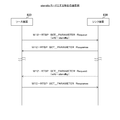
- the wireless communication unit may exchange the capability information by capability negotiation or capability re-negotiation defined in the Wi-Fi Display specification.
- the capability information is exchanged by the capability negotiation or the capability re-negotiation defined in the Wi-Fi Display specification.
- the capability information may be exchanged in RTSP M3 Message in capability negotiation or capability re-negotiation.
- the capability information is exchanged in the RTSP M3 Message in the capability negotiation or the capability re-negotiation.
- the capability information may include information indicating whether the device is a mobile device. This brings about the effect
- the capability information may include information indicating whether or not the usage of the information processing apparatus has been changed. This brings about the effect
- the capability information may include information indicating whether or not a multi-reception diversity function is provided. This brings about the effect
- control unit may perform control for intermittent transmission or stop transmission of the stream when the low power consumption mode is set. As a result, when the low power consumption mode is set, the stream is intermittently transmitted or the transmission is stopped.
- control unit transmits at least one of a transmission rate change request and a transmission quality change request to a command transmitted from the information processing apparatus to the other information processing apparatus. May be included. Accordingly, there is an effect that a command transmitted from the information processing apparatus to another information processing apparatus includes at least one of a transmission rate change request and a transmission quality change request.
- control unit may use a command in a state where an HDCP session is maintained as the command. This brings about the effect that the command in the state where the HDCP session is maintained is used.
- control unit may perform control for designating a physical layer to be used from the transport layer.
- the physical layer to be used is designated from the transport layer.
- control unit may receive physical link switching information and perform control for starting AVC / HEVC from an I frame. As a result, the physical link switching information is received, and AVC / HEVC is started from the I frame.
- a second aspect of the present technology is an information processing apparatus that transmits a stream for outputting image information to another information processing apparatus using wireless communication, and the capability related to the information processing apparatus
- a wireless communication unit that performs communication for exchanging information and capability information related to the other information processing device with the other information processing device, capability information related to the information processing device, and the other information processing
- An information processing apparatus including a control unit that performs scalability transmission rate control of a stream related to the other information processing apparatus based on control from the other information processing apparatus based on how the apparatus is used; A program for causing a computer to execute the method.
- the scalability transmission rate control of the stream related to the other information processing device is performed. Bring about an effect.
- 3 is a sequence chart illustrating an example of communication processing between devices included in the communication system 100 according to the first embodiment of the present technology.
- 3 is a sequence chart illustrating an example of communication processing between devices included in the communication system 100 according to the first embodiment of the present technology.
- 3 is a sequence chart illustrating an example of communication processing between devices included in the communication system 100 according to the first embodiment of the present technology.
- 3 is a sequence chart illustrating an example of communication processing between devices included in the communication system 100 according to the first embodiment of the present technology.
- 3 is a sequence chart illustrating an example of communication processing between devices included in the communication system 100 according to the first embodiment of the present technology.
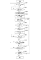
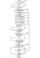
- 7 is a flowchart illustrating an example of a processing procedure of data transmission processing by the information processing device 200 according to the first embodiment of the present technology.
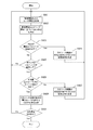
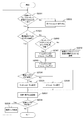
- FIG. 7 is a flowchart illustrating an example of a processing procedure of a data transmission rate control process by the information processing device 300 according to the first embodiment of the present technology.
- 3 is a sequence chart illustrating a communication processing example between a source device and a sink device according to the first embodiment of the present technology.
- 3 is a sequence chart illustrating a communication processing example between a source device and a sink device according to the first embodiment of the present technology.
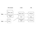
- 3 is a sequence chart illustrating a communication processing example between a source device and a sink device according to the first embodiment of the present technology. It is a block diagram which shows the system configuration example of the communication system 700 in 2nd Embodiment of this technique.
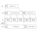
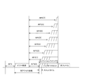
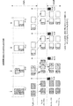
- FIG. 22 is a flowchart illustrating an example of a processing procedure of a frequency channel setting process performed by the information processing device 300 according to the second embodiment of the present technology. It is a block diagram showing an example of functional composition of information processor 710 in a 2nd embodiment of this art. It is a figure showing typically a packet generated in transmission processing by information processor 710 in a 2nd embodiment of this art. It is a figure showing an example of a priority order contention access control method by information processor 710 in a 2nd embodiment of this art. It is a figure showing typically the flow of media data in the case of transmission processing by information processor 710 in a 2nd embodiment of this art.
- FIG. 27 is a flowchart illustrating an example of a processing procedure of a data transmission process performed by the information processing device 1020 according to the third embodiment of the present technology.
- 27 is a flowchart illustrating an example of a processing procedure of a data transmission process performed by the information processing device 1020 according to the third embodiment of the present technology.
- 27 is a flowchart illustrating an example of a processing procedure of a data transmission process performed by the information processing device 1020 according to the third embodiment of the present technology.
- 24 is a flowchart illustrating an example of a processing procedure of a data reception process performed by the information processing device 1010 according to the third embodiment of the present technology.
- 36 is a flowchart illustrating an example of a processing procedure of HDCP processing by the information processing device 1020 according to the third embodiment of the present technology.
- FIG. 36 is a flowchart illustrating an example of a processing procedure of HDCP processing by the information processing device 1020 according to the third embodiment of the present technology.
- 16 is a sequence chart illustrating an example of key exchange processing performed between a source device and a sink device according to the third embodiment of the present technology.
- 16 is a sequence chart illustrating an example of key exchange processing performed between a source device and a sink device according to the third embodiment of the present technology.
- It is a block diagram which shows an example of a schematic structure of a smart phone.
- It is a block diagram which shows an example of a schematic structure of a car navigation apparatus.
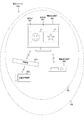
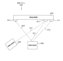
- FIG. 1 is a block diagram illustrating a system configuration example of the communication system 100 according to the first embodiment of the present technology.
- the communication system 100 includes an information processing device 200, an information processing device 300, and an information processing device 400.
- the communication system 100 is a communication system in which the information processing apparatus 300 receives data (for example, image data and audio data) transmitted from at least one of the information processing apparatus 200 and the information processing apparatus 400.
- the information processing apparatuses 200, 300, and 400 are transmission / reception devices having a wireless communication function.
- the information processing devices 200, 300, and 400 are display devices (for example, personal computers) and portable information processing devices (for example, smartphones and tablet terminals) that have a wireless communication function.
- the information processing apparatuses 200, 300, and 400 include IEEE (Institute of Electrical and Electronics Electronics) (802.11, 802.15, 802.16, 3GPP specifications (W-CDMA (Wideband Code Division Multiple Access), GSM). (Registered Trademark) (Global System for Mobile Communications), WiMAX (Worldwide Interoperability for Microwave Access), WiMAX2, LTE (Long Term Evolution), LTE-A (Advanced), etc.).
- the information processing apparatuses 200, 300, and 400 can exchange various types of information using a wireless communication function.
- Wi-Fi Wireless Fidelity
- TDLS Transmission Link Setup
- ad hoc network ad hoc network
- mesh network ad hoc network
- Wi-Fi CERTIFIED Miracast uses Wi-Fi Direct and TDLS technologies to transmit audio and display images that are played back on one terminal to other terminals, and the other terminals can transmit the audio, This is a mirroring technology that outputs image data.
- Wi-Fi CERTIFIED Miracast realizes UIBC (User Input Back Channel) on TCP / IP (Transmission Control Protocol / Internet Protocol).
- UIBC is a technique for transmitting operation information of an input device such as a mouse or a keyboard from one terminal to the other terminal.
- other remote desktop software for example, VNC (Virtual Network Computing) may be applied.
- H.Fi CERTIFIED Miracast images (videos) are recorded on, for example, H.Fi. H.264 is used for compression / decompression.
- H. H.264 can be adjusted on the transmission side.
- H. H.264, H.264 265 for example, HEVC (high-efficiency-video coding), SHVC (scalable-video coding-extensions-of high-efficiency video-coding)
- MPEG Moving-Picture Experts Group 2000
- JPEG Joint Photographic Experts Group
- various line-based codecs etc. It can also support codecs.
- the line-based codec is, for example, one that bundles and compresses one or more lines, or that compresses and decompresses by dividing two or more lines into 2 ⁇ 2 or more macroblocks.
- the line-based codec for example, wavelet transform and DCT (discrete cosine transform) can be used.
- DCT discrete cosine transform
- an image video may be transmitted or received without compression.
- the information processing apparatus 200 illustrates an example in which image data and audio data generated by an imaging operation are transmission targets.
- the information processing apparatus 400 is an example in which content (for example, content including image data and audio data) stored in a storage unit (for example, a hard disk) is a transmission target.
- a storage unit for example, a hard disk
- the information processing apparatus 200 an electronic device (for example, a personal computer, a game machine, a smartphone, or a tablet terminal) equipped with a camera may be used.
- the information processing apparatus 300 another electronic device including a display unit (for example, an imaging device, a game machine, a smartphone, or a tablet terminal) may be used.
- the information processing apparatus 400 may be provided with a tethering function, and the information processing apparatus 400 may acquire content stored in an ISP (Internet Services Provider) via a wireless or wired network and make it a transmission target. .
- ISP Internet Services Provider
- image data generated by the imaging operation of the information processing apparatus 200 is transmitted to the information processing apparatus 300, and the image 11 based on the image data is displayed on the display unit 351 of the information processing apparatus 300.
- content stored in a storage unit (for example, a hard disk) of the information processing device 400 is transmitted to the information processing device 300, and an image 12 based on the content is displayed on the display unit 351 of the information processing device 300.
- the information processing device (source device) on the source side is the information processing devices 200 and 400
- the information processing device (sink device) on the sink side is the information processing device 300.
- An example is shown.
- an information transmission range (service range) when the information processing apparatus 300 is used as a reference is illustrated as an information transmission range 101. .
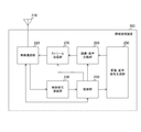
- FIG. 2 is a block diagram illustrating a functional configuration example of the information processing device 200 according to the first embodiment of the present technology. Note that the functional configuration related to wireless communication of the information processing apparatus 400 is substantially the same as that of the information processing apparatus 200. For this reason, in the first embodiment of the present technology, only the information processing apparatus 200 will be described, and the description of the information processing apparatus 400 will be omitted.
- the information processing apparatus 200 includes an antenna 210, a wireless communication unit 220, a control signal receiving unit 230, a control unit 240, an image / audio signal generation unit 250, an image / audio compression unit 260, and a stream transmission unit 270. Is provided.
- the wireless communication unit 220 uses the wireless communication to control each piece of information (for example, image data and audio data) with another information processing device (for example, the information processing device 300) based on the control of the control unit 240.
- Information processing device for example, the information processing device 300
- the wireless communication unit 220 uses the wireless communication to control each piece of information (for example, image data and audio data) with another information processing device (for example, the information processing device 300) based on the control of the control unit 240.
- the antenna 210 For example, when image data transmission processing is performed, the image data generated by the image / audio signal generation unit 250 is compressed by the image / audio compression unit 260, and the compressed image data (image stream) is wirelessly transmitted. It is transmitted from the antenna 210 via the communication unit 220.
- the wireless communication unit 220 can transmit / receive each information to / from another information processing apparatus (for example, the information processing apparatus 300) using a plurality of frequency channels.
- another information processing apparatus for example, the information processing apparatus 300
- the wireless communication unit 220 has a function capable of transmitting and receiving three types of frequency channels of 2.4 GHz, 5 GHz, and 60 GHz is shown.
- the sink device for example, the information processing apparatus 300 controls which frequency channel is used by each source device. Can do.
- the control signal receiving unit 230 includes a control signal (for example, exchange with the information processing device 300) transmitted from another information processing device (for example, the information processing device 300) among the pieces of information received by the wireless communication unit 220. Information), and outputs the acquired control signal to the control unit 240.
- a control signal for example, exchange with the information processing device 300
- another information processing device for example, the information processing device 300
- the control unit 240 performs control related to each piece of information transmitted from the information processing apparatus 200.
- the control unit 240 controls the image / sound signal generation unit 250 and the image / sound compression unit 260 based on the control signal received by the control signal receiving unit 230.
- the control unit 240 performs control for changing the resolution of the image data to be transmitted and the number of audio channels, and control for changing the image area of the image data to be transmitted. That is, the control unit 240 performs transmission control of a stream to be transmitted based on the control signal received by the control signal receiving unit 230.
- This transmission control is, for example, data transmission rate control, scalability transmission rate control, multi-reception diversity setting control, and content protection setting control. Note that the scalability transmission rate control will be described in a second embodiment of the present technology. In addition, multi-reception diversity setting control and content protection setting control will be described in a third embodiment of the present technology.
- control unit 240 has a function of measuring a radio wave propagation state (link radio wave propagation state) when data is transmitted / received to / from the sink device using wireless communication, and the measurement result (the radio wave) Propagation measurement information) may be transmitted to the sink device.
- the radio wave propagation measurement information is, for example, information used when determining whether or not the line quality with the sink device is a quality capable of transmitting and receiving image data and audio data.
- the radio wave propagation measurement information is used, for example, when performing stream transmission control (for example, data transmission rate control, scalability transmission rate control, multi-reception diversity setting control, content protection setting control).
- the radio wave propagation measurement information will be described in detail with reference to FIG.
- the control unit 240 may count the number of retransmissions of the same packet, and the stream transmission control may be performed based on the count number.
- the data transmission rate mainly means the rate of occupying the communication path, and includes the meaning of communication speed and communication capacity.
- the resolution is defined as an index of image quality composed of elements such as an image data image frame (vertical and horizontal number of pixels) and image data bit rate (compression rate).
- the stream throughput can be used as an image quality index.
- the number of audio channels includes the meaning of audio recording / playback methods such as monaural (1.0 ch) and stereo (2.0 ch).
- the number of audio channels is defined as a sound quality index composed of elements such as the bit rate (compression rate) of audio data and the number of channels. Further, the stream throughput can be used as an index of sound quality.
- control unit 240 performs control for improving a state that cannot be stabilized by data rate control.
- the control unit 240 grasps the system performance information of the sink device by exchanging information with the sink device (for example, the information processing apparatus 300).
- the system performance information is, for example, performance information related to the sink device system.
- the system performance information includes usable frequency channels, resolution, TCP (Transmission Control Protocol), and UDP (User Datagram Protocol).
- the system performance information is information indicating, for example, encryption method support, SD (Standard Definition) / HD (High Definition) support, and low power consumption mode support.
- control unit 240 performs stream transmission control (for example, data transmission rate control, etc.) that further improves the stability of the entire system of the communication system 100 depending on whether the sink device supports the low power consumption mode. (Scalability transmission rate control) method can be selected.
- the control unit 240 puts information on whether or not the information processing apparatus 200 is a mobile device in the exchange of information with the information processing apparatus 300.
- information on whether or not the information processing apparatus 200 is a mobile device can be included in the capability information regarding the information processing apparatus 200.
- the information processing apparatus 300 recognizes that the information processing apparatus 200 is a mobile device, the information processing apparatus 300 determines that it is not necessary to operate the information processing apparatus 200 based on the relationship with another information processing apparatus connected thereto. Can do.
- the information processing apparatus 200 receives a transmission stop command from the information processing apparatus 300.
- control unit 240 When the control unit 240 grasps the transmission stop command, the control unit 240 can power down the functions of the image / audio signal generation unit 250, the image / audio compression unit 260, and the stream transmission unit 270 for a certain period of time. it can. In addition, the control unit 240 can also shift the wireless communication unit 220 to intermittent reception (a mode in which the wireless communication unit 220 periodically wakes up to such an extent that a command can be received from the information processing apparatus 300 and the other is a power-down mode).
- intermittent reception a mode in which the wireless communication unit 220 periodically wakes up to such an extent that a command can be received from the information processing apparatus 300 and the other is a power-down mode.
- the image / sound signal generation unit 250 generates data (image data, sound data) to be output based on the control of the control unit 240, and outputs the generated data to the image / sound compression unit 260.
- the image / sound signal generation unit 250 includes an imaging unit (not shown) and a sound acquisition unit (not shown).
- the imaging unit for example, a lens, an imaging element, and a signal processing circuit
- the sound acquisition unit for example, a microphone
- the data generated in this way becomes a transmission target to another information processing apparatus (for example, the information processing apparatus 300).
- the image / sound compression unit 260 compresses (encodes) the data (image data and sound data) generated by the image / sound signal generation unit 250 based on the control of the control unit 240. Then, the image / audio compression unit 260 outputs the compressed data (image data and audio data) to the stream transmission unit 270.
- the control unit 240 determines whether to cause the image / audio compression unit 260 to perform compression and non-compression of data based on whether the source device or the sink device is a mobile device. May be. That is, the control unit 240 may determine whether to transmit the compressed data as it is without transcoding based on whether the source device or the sink device is a mobile device.
- the image / audio compression unit 260 can output the data generated by the image / audio signal generation unit 250 without compression.
- the image / sound compression unit 260 may be realized by execution of encoding by software, or may be realized by execution of encoding by hardware.
- the image / sound compression unit 260 is assumed to function as a codec, but can handle uncompressed images or sounds.
- the image / sound compression unit 260 can also function as a scalable codec.
- the scalable codec means a codec that can be freely adapted according to, for example, the resolution of the information processing apparatus (sink device) on the receiving side, the network environment, and the like. Note that the scalable codec will be described in detail in a second embodiment of the present technology.
- the stream transmission unit 270 transmits the data (image data and audio data) compressed by the image / audio compression unit 260 as a stream from the antenna 210 via the wireless communication unit 220 based on the control of the control unit 240. The processing is performed.
- the information processing apparatus 200 can include a display unit, an audio output unit, an operation reception unit, and the like in addition to the above-described units, which are not illustrated in FIG. Further, although an example in which the information processing device 200 generates image data and audio data to be transmitted is shown, the information processing device 200 may acquire image data and audio data to be transmitted from an external device. Good. For example, the information processing apparatus 200 may acquire image data and audio data to be transmitted from a web camera with a microphone. In addition, the information processing apparatus 200 transmits content (for example, content including image data and audio data) stored in a storage device (for example, a hard disk) regardless of whether the information processing apparatus 200 is inside or outside. You may do it.
- a storage device for example, a hard disk
- the content stored in the storage device is a compressed content.
- the compressed content is compressed by the encoding method defined by the standard adopted by the communication system 100, the compressed content is transmitted without being decoded. You may make it do.
- the display unit (not shown) of the information processing apparatus 200 is a display unit that displays an image generated by the image / audio signal generation unit 250, for example.
- a display panel such as an organic EL (Electro Luminescence), a crystal LED (Light Emitting Diode) display (Crystal LED Display), or an LCD (Liquid Crystal Display) can be used as the display unit.
- the audio output unit (not shown) of the information processing apparatus 200 is an audio output unit (for example, a speaker) that outputs the audio generated by the image / audio signal generation unit 250, for example.
- the image can be output from both the transmitting device and the receiving device, but the sound is preferably output from only one of them.
- the operation reception unit (not shown) of the information processing apparatus 200 is an operation reception unit that receives an operation input performed by a user, and is, for example, a keyboard, a mouse, a game pad, a touch panel, a camera, and a microphone.
- the operation receiving unit and the display unit can be integrally configured using a touch panel that allows a user to input an operation by touching or approaching the finger with the display surface.
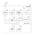
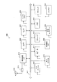
- FIG. 3 is a block diagram illustrating a functional configuration example of the information processing device 300 according to the first embodiment of the present technology.
- the information processing apparatus 300 includes an antenna 310, a wireless communication unit 320, a stream reception unit 330, an image / sound development unit 340, an image / sound output unit 350, a user information acquisition unit 360, a control unit 370, A control signal transmission unit 380 and a management information holding unit 390 are provided.
- the wireless communication unit 320 uses wireless communication to control each piece of information (for example, image data and audio data) with another information processing device (for example, the information processing device 200) based on the control of the control unit 370.
- Information processing device for example, the information processing device 200
- the wireless communication unit 320 uses wireless communication to control each piece of information (for example, image data and audio data) with another information processing device (for example, the information processing device 200) based on the control of the control unit 370.
- image data reception processing image data received by the antenna 310 is expanded (decoded) by the image / sound expansion unit 340 via the wireless communication unit 320 and the stream reception unit 330.
- the developed image data is supplied to the image / sound output unit 350, and an image corresponding to the developed image data is output from the image / sound output unit 350. That is, an image corresponding to the developed image data is displayed on the display unit 351.
- the wireless communication unit 320 can transmit and receive each piece of information with another information processing apparatus (for example, the information processing apparatus 200) using a plurality of frequency channels.
- another information processing apparatus for example, the information processing apparatus 200
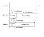
- the wireless communication unit 320 has a function capable of transmitting and receiving three types of frequency channels of 2.4 GHz, 5 GHz, and 60 GHz is shown. That is, the wireless communication unit 320 can perform communication using the first frequency band and communication using the second frequency band having a higher data transmission rate than the first frequency band.
- the control unit 370 controls which frequency channel of the plurality of frequency channels is used for wireless communication with each source device.
- the link between the information processing device 200 and the information processing device 300 and the link between the information processing device 400 and the information processing device 300 may be the same frequency channel or different frequency channels. Also good.
- the wireless communication unit 320 has a function capable of transmitting and receiving three types of frequency channels of 2.4 GHz, 5 GHz, and 60 GHz is shown, but the present invention is not limited to this.
- the wireless communication unit 320 may have a function capable of transmitting and receiving other frequency channels and two or more frequency channels.
- the stream receiving unit 330 Based on the control of the control unit 370, the stream receiving unit 330 receives information and a stream (for example, an image stream and an audio stream) of exchange with each source device from among the information received by the wireless communication unit 320. To do. Then, the stream reception unit 330 outputs the received command information to the control unit 370, and outputs the received stream to the image / audio development unit 340 and the control unit 370.
- a stream for example, an image stream and an audio stream
- the information on the exchange with each source device is information transmitted from the source device (for example, the information processing apparatus 200) and includes, for example, an acquisition request for system performance information of the information processing apparatus 300.
- This system performance information is information indicating, for example, usable frequency channels, resolution, TCP, UDP, encryption method support, SD / HD support, and low power consumption mode support.
- the stream receiving unit 330 has a function of measuring a radio wave propagation state (link radio wave propagation state) when data is transmitted / received to / from the sink device using wireless communication. Then, the stream receiving unit 330 outputs the measurement result (radio wave propagation measurement information) to the control unit 370.
- the radio wave propagation measurement information will be described in detail with reference to FIG.
- the image / sound developing unit 340 develops (decodes) a stream (image data and sound data) transmitted from another information processing apparatus (for example, the information processing apparatus 200) based on the control of the control unit 370. is there. Then, the image / sound developing unit 340 outputs the developed data (image data and sound data) to the image / sound output unit 350.
- the image / sound decompression unit 340 may be realized by executing decoding by software, or may be realized by executing decoding by hardware.
- the image / sound development unit 340 is assumed to function as a codec, but is assumed to be able to handle uncompressed images or sounds.
- the image / sound developing unit 340 can also function as a scalable codec.
- the image / sound output unit 350 includes a display unit 351 and a sound output unit 352.
- the display unit 351 is a display unit that displays each image (for example, the images 11 and 12 shown in FIG. 1) based on the image data developed by the image / sound developing unit 340.
- a display panel such as an organic EL panel, a crystal LED display, or an LCD panel can be used.
- a touch panel on which a user can perform an operation input by touching or approaching his / her finger to the display surface may be used.
- the sound output unit 352 is a sound output unit (for example, a speaker) that outputs various sounds (such as sound related to the image displayed on the display unit 351) based on the sound data developed by the image / sound development unit 340.
- a sound output method for example, a method of reproducing only the sound of the source device assigned to the main image from the speaker and not reproducing the sound of the source device assigned to the sub image can be used.
- a method is used in which the volume of the sound of the source device assigned to the main image is set as the main and the sound volume of the source device assigned to the sub image is reduced and played back. Can do. Note that other audio output methods may be used.
- the user information acquisition unit 360 acquires information about the user (user information), and outputs the acquired user information to the control unit 370.
- the user information acquisition unit 360 can acquire user information by receiving input from an operation reception unit (keyboard, mouse, remote controller, game pad, touch panel) that allows the user to directly set the display method.
- the operation accepting unit is an operation member for designating an arbitrary region in the image displayed on the display unit 351, for example.
- the user information acquisition unit 360 receives an input from a device that can grasp the user's intention such as a camera, a microphone, various sensors (for example, a gyro sensor, a sensor that senses a human body), and the like. User information can be acquired.
- the user information acquisition unit 360 is a user when information based on a stream received from another information processing apparatus (for example, the information processing apparatus 200) using wireless communication is output from the image / sound output unit 350.
- User information generated by the operation is acquired.
- This user information is user information generated by a user operation relating to an image displayed on the display unit 351, for example.
- the user information is information generated based on a user operation related to the image displayed on the display unit 351.
- the control unit 370 holds each piece of information acquired by the stream receiving unit 330 in the management information holding unit 390, and manages each source device based on the management information held in the management information holding unit 390.
- the control unit 370 controls stream transmission (for example, data transmission rate control, scalability transmission rate control, and multi-receive diversity setting control so that the stability of the streams transmitted from a plurality of source devices is improved in the entire system. )I do.
- the control unit 370 controls stream transmission (for example, data transmission rate control, scalability transmission) based on the user information acquired by the user information acquisition unit 360 and the management information held in the management information holding unit 390. Rate control, multi-receive diversity setting control, content protection setting control). Specifically, the control unit 370 controls stream transmission (for example, data transmission rate control, scalability transmission rate control, multi-receive diversity setting control, based on the management information held in the management information holding unit 390. A control signal for performing content protection setting control) is generated for each source device, and the generated control signal is output to the control signal transmission unit 380.
- stream transmission for example, data transmission rate control, scalability transmission
- a control signal for performing content protection setting control is generated for each source device, and the generated control signal is output to the control signal transmission unit 380.
- control unit 370 changes the resolution of the image displayed on the display unit 351 based on the user information and management information, and generates a control signal for requesting each source device to transmit a transmission rate equivalent to this resolution. To do. Further, for example, the control unit 370 generates a control signal for changing the image display area in the display unit 351 based on the user information and the management information. For example, the control unit 370 generates a control signal for changing the size of the image on the display unit 351 based on the user information and the management information.
- control unit 370 performs control for setting the frequency channel to be used and the resolution based on the user information and management information. For example, the control unit 370 sets a frequency channel to be used for each source device for a plurality of frequency channels included in the wireless communication unit 320. In addition, when the power consumption mode is different for each frequency channel, the control unit 370 can grasp each mode and set a frequency channel that cares about the power consumption of the mobile device. That is, the control unit 370 separately sets the first power consumption mode related to the first frequency band and the second power consumption mode related to the second frequency band having a higher data transmission rate than the first frequency band. can do.
- the control signal transmission unit 380 performs transmission processing for transmitting the control signal output from the control unit 370 to another wireless communication device via the wireless communication unit 320 and the antenna 310.
- the management information holding unit 390 is a table that holds information (management information) for managing each source device connected to the information processing apparatus 300 using wireless communication. The contents held by the management information holding unit 390 will be described in detail with reference to FIG.
- FIG. 4 is a diagram schematically illustrating an example of contents held by the management information holding unit 390 according to the first embodiment of the present technology.
- the management information holding unit 390 is a table that holds information (management information) for managing each source device connected to the information processing apparatus 300 using wireless communication.
- the management information holding unit 390 includes terminal identification information 391, frequency channel 392, radio wave propagation measurement information 393, device information 394, band usage level 395, output form 396, standby / wakeup 397, A multi-receive diversity correspondence 398 is held in association with each other.
- the terminal identification information 391 stores identification information for identifying a source device connected to the information processing apparatus 300 using wireless communication.
- the frequency channel 392 stores the frequency channel actually used by the source device connected to the information processing apparatus 300 using wireless communication.
- the radio wave propagation measurement information 393 stores radio wave propagation measurement information related to the source device connected to the information processing apparatus 300 using wireless communication.
- the radio wave propagation measurement information is measured by the stream receiving unit 330 for each source device connected to the information processing apparatus 300 using wireless communication.
- radio wave propagation measurement information 393 for example, PER (Packet Error Rate), BER (Bit Error Rate), the number of packet retransmissions, and throughput are stored. Further, as the radio wave propagation measurement information 393, for example, a frame drop, SIR (Signal-to-Interference-Ratio), and RSSI (Received-Signal-Strength-Indicator) are stored. Here, SINR (Signal to (Interference plus Noise Ratio) may be used instead of SIR. Note that the radio wave propagation measurement information 393 illustrated in FIG. 4 is an example, and at least one of these may be stored, and other radio wave propagation measurement information is measured and stored by the stream reception unit 330. You may do it.
- radio wave propagation measurement information measured by the source device may be acquired and stored. Further, the packet delay received by the receiving side may be determined, and information regarding this packet delay may be used as the radio wave propagation measurement information.
- This packet delay is one indicator for radio wave propagation because, for example, when an error occurs, a delay occurs in transmission to the receiving side due to retransmission processing in layer 2. Further, the packet delay is an index indicating whether some link characteristic is deteriorated in a wireless system in which a plurality of devices share a wireless band, for example.
- the device information 394 stores the type (source device attribute) of the source device connected to the information processing apparatus 300 using wireless communication. For example, either a mobile device or a stationary device is stored as the source device type. Note that, as the type of the source device, either a device that is used while the power is inserted or another device may be stored. Further, as the type of the source device, either a battery-driven device or any other device may be stored.
- the bandwidth usage level 395 stores the bandwidth usage level by the source device connected to the information processing apparatus 300 using wireless communication.
- the band usage level for example, resolution or throughput can be used.
- the bandwidth usage level may store the throughput being used.
- a predetermined table is prepared, and a number indicating which range of the table corresponds is stored and managed. You may do it.
- the output form 396 stores an output form of data based on a stream transmitted from a source device connected to the information processing apparatus 300 using wireless communication.
- the display form (main image, sub image) in the display unit 351 of the image data based on the stream transmitted from the source device is stored.
- the output form (main audio, sub audio) of the audio data based on the stream transmitted from the source device from the audio output unit 352 is stored. Note that, depending on the display form, a form in which no sub-image is displayed may be used.
- the standby / wakeup 397 stores the mode of the source device connected to the information processing apparatus 300 using wireless communication (standby mode, wakeup mode).
- the standby mode and wake-up mode will be described in detail with reference to FIGS.
- the multi-reception diversity support 398 stores information indicating whether the source device connected to the information processing apparatus 300 using wireless communication is compatible with multi-reception diversity. Note that multi-reception diversity will be described in detail in a third embodiment of the present technology.
- the management information held in the management information holding unit 390 associates identification information (terminal identification information 391) for identifying another information processing apparatus and capability information related to the other information processing apparatus.
- the management information held in the management information holding unit 390 includes, as capability information related to other information processing apparatuses, information related to radio wave propagation measurement related to communication with other information processing apparatuses (radio wave propagation measurement information 393), power consumption Information (standby / wakeup 397).
- the management information held in the management information holding unit 390 includes at least information related to an output form for displaying image information (output form 396) as capability information related to another information processing apparatus.
- the information relating to the output form is, for example, information indicating that the image information is main-displayed or sub-displayed.
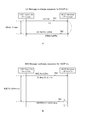
- FIG. 5 is a diagram illustrating a transition example of an image displayed on the display unit 351 of the information processing device 300 according to the first embodiment of the present technology.
- 5A shows an example of a display form in which the image 11 is the main image, the image 12 is the sub-image, and the image 11 and the image 12 are displayed on the display unit 351 of the information processing apparatus 300.
- 5B illustrates an example of a display form in which the image 11 and the image 12 are displayed on the display unit 351 of the information processing apparatus 300 with the image 11 as a sub-image and the image 12 as a main image.
- each of the information processing device 200 and the information processing device 400 transmits a standard resolution stream (image data and audio data) to the information processing device 300.
- the image 11 based on the image data from the information processing device 200 and the image 12 based on the image data from the information processing device 400 have the same size.
- the information can be displayed on the display unit 351 of the information processing apparatus 300.
- the given resolution and display area are defined to be the same.
- a scaler function is added to the display unit 351 so that the images 11 and 12 are rescaled and displayed on the display unit 351. May be.
- this function is not used in order to simplify the description.
- each display form of the image 11 and the image 12 for example, the display form set at the previous communication is held, and the images 11 and 12 are displayed in the display unit of the information processing apparatus 300 according to the display form. 351 may be displayed.
- each of the images 11 and 12 may be determined based on the order of connection to the information processing apparatus 300.
- the information processing apparatus 200 is first connected to the information processing apparatus 300 and the information processing apparatus 400 is connected to the information processing apparatus 300 after this connection.
- the image 11 and the image 12 are displayed on the display unit 351 of the information processing apparatus 300 with the image 11 as a main image and the image 12 as a sub-image. That is, the main image and the sub image may be displayed in this order based on the connection order to the information processing apparatus 300.
- the image 11 is the main image
- the image 12 is the sub-image
- the image 11 and the image 12 are displayed on the display unit 351, the user who uses the image 12 as the main image.
- information is acquired by the user information acquisition unit 360.
- the viewer performs an operation for making the image 12 the main image using a pointer such as a remote controller or a gesture
- user information using the image 12 as the main image is acquired by the user information acquisition unit 360.
- the image 11 and the image 12 are displayed on the display unit 351 with the image 12 as a main image and the image 11 as a sub-image.
- the display positions of the image 11 and the image 12 on the display surface of the display unit 351 are also determined based on user information (for example, manual operation, line of sight) acquired by the user information acquisition unit 360.
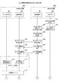
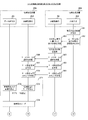
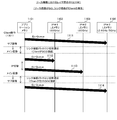
- Example of communication 6 to 8 are sequence charts illustrating communication processing examples between devices included in the communication system 100 according to the first embodiment of the present technology. 6 to 8 illustrate examples of communication processing between the information processing apparatus 200 and the information processing apparatus 300.
- the image / audio signal generation unit 250, the image / audio compression unit 260, and the stream transmission unit 270 are shown as the data transmission system 201 among the units constituting the information processing apparatus 200.
- the antenna 210, the wireless communication unit 220, the control signal receiving unit 230, and the control unit 240 are shown as a line control system 202.
- the antenna 310, the wireless communication unit 320, the stream reception unit 330, the control unit 370, and the control signal transmission unit 380 are shown as the line control system 301 among the units constituting the information processing apparatus 300. Also, the image / sound development unit 340, the image / sound output unit 350, and the user information acquisition unit 360 are shown as the input / output system 302.
- FIGS. 6 to 8 show a connection setup example of the information processing device 200 and the information processing device 300 and a transition example of the power consumption mode in the information processing device 200.
- the control unit 370 of the information processing device 300 causes the management information holding unit 390 (shown in FIG. 4) to hold management information of each source device connected to the information processing device 300 using wireless communication.
- the control unit 370 of the information processing device 300 displays the images 11 corresponding to the two streams transmitted from each of the information processing device 200 and the information processing device 400 based on the previous output form. , 12 are displayed on the display unit 351.
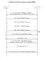
- the information processing apparatus 200 transmits a mode table request (inquiry request for resolution / sound quality, low power consumption mode, etc.) to the information processing apparatus 300 periodically or irregularly (including only at the start) (505, 506).
- This mode table request includes information managed by the information processing device 300 (management information related to the information processing device 300 and information used for communication with the information processing device 200 (for example, displayed by the information processing device 200). Request for possible resolution information, etc.)).
- the information processing apparatus 300 transmits command information corresponding to the mode table request (507, 508).
- This command information is information about the information processing apparatus 200 for the information processing apparatus 300 to make a setting request to the information processing apparatus 200 in consideration of, for example, a radio wave propagation environment and a display form.
- the command information is information including resolution / sound quality output form information (for example, main image, sub-image), availability of low power consumption mode, manufacturer name, and presence / absence of multi-reception diversity function.
- the command information includes resolution / sound quality, image / audio codec type, 3D function presence / absence, content protection presence / absence, display device display size, topology information, usable protocols, and setting information for these protocols ( Port information, etc.), connection interface information (connector type, etc.), horizontal synchronization / vertical synchronization position, source device performance priority request information, mode control table response such as availability of low power consumption mode, wireless transmission maximum This is information including throughput or maximum receivable throughput, CPU (Central Processing Unit) power, remaining battery power, and power supply information. Each of these pieces of information is included in a part of capability information.
- the output form information of resolution / sound quality related to the information processing apparatus 200 is information indicating whether the output form of data from the information processing apparatus 200 is main or sub, for example. Further, the information processing apparatus 300 transmits a request regarding the setting of the resolution / sound quality and the low power consumption mode as a parameter in the command information from the viewpoint of the information processing apparatus 300. Note that the information processing apparatus 300 may transmit, as command information, information related to all source devices in addition to information related to the information processing apparatus 200. In this case, the information processing apparatus 200 selects and uses only information for the own apparatus.
- the control unit 240 of the information processing device 200 specifies whether the data output form from the information processing device 200 is main or sub based on the command information. . In addition, the control unit 240 of the information processing device 200 determines whether the information processing device 300 has a function corresponding to the power consumption operation mode based on the command information. Subsequently, the control unit 240 of the information processing apparatus 200 transmits mode setting information indicating that the specified output form is set to the information processing apparatus 300 (509, 510). Here, it is assumed that the output form of data from the information processing apparatus 200 is specified as sub. Further, it is assumed that the information processing apparatus 300 has a function corresponding to the low power consumption mode. Therefore, the control unit 240 of the information processing device 200 notifies the information processing device 300 of mode setting information for notifying that the specified output form (sub) is set and that the low power consumption mode is set. Transmit (509, 510).
- the low power consumption mode is set by specifying whether the image is a main image or a sub image based on command information, but it is determined whether the image is a main image or a sub image.
- the low power consumption mode may be set without using it as a reference.
- the low power consumption mode may be set by exchanging permission flags that can be shifted to the low power consumption mode between the source device and the sink device.
- the control unit 240 of the information processing apparatus 200 sets the sub mode as the transmission mode (511).
- the data transmission system 201 sets the resolution for displaying the sub image and the sound quality for outputting the sub sound (512).
- the low power consumption mode is set (513).
- both the sink device and the source device need to have the function.
- mobile devices for example, mobile phones, smartphones, tablet terminals
- the output form of the data from the own apparatus is not main (when it is a sub)
- the setting process (512) only the sound of the source device assigned to the main image may be reproduced from the speaker and the sound of the source device assigned to the sub image may not be reproduced.
- the sound volume of the source device assigned to the main image may be set as the main, and the sound volume of the source device assigned to the sub image may be set to be played back.
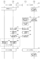
- control unit 370 of the information processing device 300 performs control for setting the information processing device 200 in the low power consumption mode when the output form is set as the sub image (sub display). That is, the control unit 370 of the information processing device 300 performs control to set the power consumption mode in the information processing device 200 based on the output form of the display unit 351 that outputs image information based on the stream.
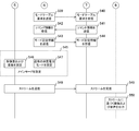
- the control unit 240 of the information processing apparatus 200 starts intermittent transmission (514 to 522).
- the information processing apparatus 200 stops the transmission process for a predetermined time and sleeps each unit (514). Subsequently, when a certain time elapses (514), the information processing apparatus 200 In order to perform the transmission process, each part of the information processing apparatus 200 is waked up, and the transmission process to the information processing apparatus 300 is performed (515 to 520).
- control unit 240 of the information processing device 200 transmits an inquiry message to the information processing device 300 to confirm whether or not there is any change (for example, a change in output form) in the information processing device 300 (515, 516).
- any change for example, a change in output form
- the control unit 370 of the information processing device 300 transmits a response message for notifying whether there is any change (for example, change of output form) to the information processing device 200 ( 517, 518).
- a response message for notifying whether there is any change for example, change of output form
- the control unit 370 of the information processing device 300 transmits a response message for notifying that there is no change (for example, change in output form) to the information processing device 200 (517, 518).
- the control unit 240 of the information processing device 200 transmits a stream for outputting the sub image and the sub sound to the information processing device 300 (519, 520).
- the information processing apparatus 300 outputs an image and sound based on the received stream (521). For example, as illustrated in b of FIG. 5, the image 11 based on the stream from the information processing apparatus 200 is displayed on the display unit 351 as a sub image.
- the information processing apparatus 200 stops the transmission process for a predetermined time and sleeps each unit (522). Further, intermittent transmission is continuously performed until there is a change request from the information processing apparatus 300.
- the information processing apparatus 300 performs display processing such that an image corresponding to the stream received from the information processing apparatus 200 is interpolated and displayed.
- the information processing apparatus 300 does not have an interpolation processing function.
- the image from the information processing apparatus 200 cannot be displayed on the display unit 351 during the sleep period.
- the transmission of image data from the information processing apparatus 200 may be continuously performed. For example, the last image data when the transmission is stopped among the streams to be transmitted from the information processing apparatus 200 is held in the transmission buffer.
- the image processing of the information processing apparatus 200 is stopped, but the transmission processing is continuously performed for the wireless link, and the transmission of the image data held in the transmission buffer is continuously performed.
- only the image corresponding to the stream transmitted from the information processing apparatus 400 may be displayed on the display unit 351.
- an image corresponding to the stream transmitted from the information processing apparatus 400 can be displayed on the entire surface of the display unit 351.
- the control unit 370 When an output mode setting operation (change operation) is performed by the user (531), as described above, the control unit 370, based on the user information related to the setting operation, the management information holding unit 390 (FIG. The content held in (4) is changed (532, 533).
- the management information holding unit 390 (FIG. The content held in (4) is changed (532, 533).
- a setting operation (change operation) for setting the image 11 based on the image data from the information processing apparatus 200 as a main image is performed.
- the control unit 370 changes the output form 396 (shown in FIG. 4) of the information processing apparatus 200 in the management information holding unit 390 to “main” (532, 533).
- the control unit 370 of 300 sets a change trigger (534).
- the change trigger is a trigger for notifying the information processing apparatus 200 that the user has performed an output mode setting operation (change operation) when an inquiry message is received from the information processing apparatus 200. With this change trigger, the information processing apparatus 200 is released from the standby mode, and the information processing apparatus 200 is notified that the output mode setting operation (change operation) has been performed by the user.
- each part of the information processing apparatus 200 is woken up and transmission processing to the information processing apparatus 300 is started.
- the control unit 370 of the information processing device 300 transmits a Standby release message to the information processing device 200 (535, 536).
- the control unit 240 of the information processing device 200 Upon receiving the Standby release message (536), the control unit 240 of the information processing device 200 transmits a response message to the information processing device 300 (537, 538).
- the control unit 240 of the information processing apparatus 200 transmits a mode table request to the information processing apparatus 300 (539, 540).
- this mode table request requests transmission of each piece of information managed by the information processing apparatus 300 (management information related to the information processing apparatus 200).
- an exchange for example, a response message to the inquiry message in each process (515 to 518)
- a change for example, a change in output form
- the information processing apparatus 300 transmits command information corresponding to the mode table request (541, 542).
- the information processing apparatus 300 may transmit only the difference information as the command information corresponding to the mode table request (541, 542).
- This difference information is information relating to the change, for example, resolution / sound quality output form information regarding the information processing apparatus 200.
- the control unit 240 of the information processing device 200 specifies whether the data output form from the information processing device 200 is main or sub based on the command information. . Subsequently, the control unit 240 of the information processing apparatus 200 transmits mode setting information indicating that the specified output form is set to the information processing apparatus 300 (543, 544). Here, it is assumed that the data output form from the information processing apparatus 200 is specified to be main. Therefore, the control unit 240 of the information processing device 200 sends mode setting information for notifying that the specified output form (main) is set and that the normal power consumption mode is set. (543, 544).
- each process (539 to 544) may be performed by Capability Re-negotiation.
- Capability Re-negotiation it is not necessary to negotiate again for the setting value in which the output form does not change in the process (534). Examples thereof include wfd-displayedid, wfd-client-rtports, wfd-I2C, and wfd-connectortype.
- the control unit 240 of the information processing apparatus 200 sets the main mode as the transmission mode (545).
- the data transmission system 201 sets the resolution for displaying the main image and the sound quality for outputting the main audio (546).
- a normal power consumption mode is set (547).
- the control unit 240 of the information processing apparatus 200 starts normal transmission processing (548, 549). That is, the information processing apparatus 200 transmits a stream for outputting a main image and main audio to the information processing apparatus 300 (548, 549).
- the information processing apparatus 300 outputs an image and sound based on the received stream (550). For example, as illustrated in a of FIG. 5, the image 11 based on the stream from the information processing device 200 is displayed on the display unit 351 as the main image.
- the previous output form (the output form when the information processing apparatus 300 is turned off) is set as the display form of the display unit 351. Indicated.
- another output form may be set.
- the default output form may be always set. Or you may make it determine a display form based on the order connected to the information processing apparatus 300.
- FIGS. 6 to 8 show an example in which the information processing apparatus 200 inquires about setting information of the information processing apparatus 300 and sets transmission parameters based on the received parameter information.
- the parameter to be set by the information processing apparatus 200 may be requested to the information processing apparatus 300, and the parameter may be set when the information processing apparatus 300 receives a response indicating that there is no problem. An example of this is shown in FIGS.
- Example of communication 9 to 11 are sequence charts illustrating communication processing examples between devices included in the communication system 100 according to the first embodiment of the present technology. 9 and 10 are obtained by modifying a part of the communication processing examples shown in FIGS. For this reason, in FIG. 9 and FIG. 10, parts common to the communication processing examples shown in FIG. 6 to FIG. FIG. 11 is a modification of a part of the communication processing example shown in FIG. For this reason, in FIG. 11, parts common to the communication processing example shown in FIG. 9 are denoted by the same reference numerals, and a part of these descriptions is omitted.
- Each process (561 to 564) shown in FIG. 9 corresponds to each process (501 to 504) shown in FIG.
- the control unit 370 of the information processing device 300 transmits a mode status notification for notifying the output form set by the user to the information processing device 200 (565, 566).
- This mode status notification includes the output form (for example, main or sub) set by the user, the resolution / sound quality that can be set by the information processing apparatus 200, the type of image / audio codec, and the presence / absence of the 3D function.
- Presence / absence of content protection display size of display device, topology information, usable protocols, setting information of these protocols (port information, etc.), connection interface information (connector type, etc.), position of horizontal / vertical synchronization, source To notify device performance priority request information, mode control table response such as compatibility with low power consumption mode, maximum wireless transmission or receivable maximum throughput, CPU power, remaining battery power, power supply information, etc. Information.
- the mode status notification for notifying the output mode related to the setting operation can be transmitted to the information processing apparatus 200. For this reason, the set time (change time) between the information processing apparatus 200 and the information processing apparatus 300 connected by using wireless communication can be shortened.
- the control unit 240 of the information processing device 200 compares the status parameter specified by the received mode status notification with the status parameter of the own device. Subsequently, the control unit 240 of the information processing apparatus 200 determines setting contents (for example, resolution / audio, power consumption mode) based on the comparison result. Subsequently, the control unit 240 of the information processing device 200 transmits a mode setting request for notifying the determined setting contents (for example, resolution / audio, power consumption mode) to the information processing device 300 (567, 568). ).
- the control unit 370 of the information processing device 300 determines whether or not to permit the setting contents (for example, resolution / audio, power consumption mode) specified by the received mode setting request. To do. Then, the control unit 370 of the information processing device 300 transmits a mode setting availability command for notifying the determination result to the information processing device 200 (569, 570).
- the setting contents for example, resolution / audio, power consumption mode
- the control unit 240 of the information processing apparatus 200 confirms the content of the mode setting availability command. For example, when a mode setting permission / prohibition command for permitting the setting content related to the mode setting request transmitted by the information processing apparatus 200 is received, the control unit 240 of the information processing apparatus 200 sets the submode as the transmission mode. (571).
- Each process (571 to 574) shown in FIG. 9 corresponds to each process (511 to 514) shown in FIG.
- the processes (575 to 578) shown in FIG. 10 correspond to the processes (519 to 522) shown in FIG.
- the control unit 240 of the information processing device 200 when the mode setting availability command indicating that the setting content related to the mode setting request transmitted by the information processing device 200 is not permitted is received, the control unit 240 of the information processing device 200 newly sets the setting content (for example, resolution / Sound, power consumption mode). Then, the control unit 240 of the information processing device 200 transmits a mode setting request for notifying the newly determined setting contents (for example, resolution / audio, power consumption mode) to the information processing device 300.
- the setting content for example, resolution / Sound, power consumption mode
- Each process (581 to 583) shown in FIG. 10 corresponds to each process (531 to 533) shown in FIG.
- the control unit 370 of the information processing device 300 transmits a mode status change notification for notifying the output form changed by the user to the information processing device 200 (584, 585).
- This mode status change notification indicates the output form (for example, main or sub) changed by the user, the resolution / sound quality that can be set by the information processing apparatus 200, the compatibility with the low power consumption mode, and the like. This is information for notification.
- the control unit 240 of the information processing device 200 determines the setting contents (for example, resolution / voice, power consumption mode).
- the setting content determination process is the same as the determination process described above.
- the control unit 240 of the information processing device 200 transmits a mode change request for notifying the determined setting contents (for example, resolution / voice, power consumption mode) to the information processing device 300 (586, 587). ).
- the control unit 370 of the information processing device 300 determines whether or not to allow the setting contents (for example, resolution / audio, power consumption mode) specified by the received mode change request. To do. Then, the control unit 370 of the information processing device 300 transmits a mode setting availability command for notifying the determination result to the information processing device 200 (588, 589).
- the setting contents for example, resolution / audio, power consumption mode
- the control unit 240 of the information processing apparatus 200 confirms the content of the mode setting availability command and sets the transmission mode (590).
- This confirmation process is the same as the confirmation process described above. Further, the processes (590 to 595) shown in FIG. 10 correspond to the processes (545 to 550) shown in FIG.
- information indicating the switching timing (for example, information for grasping the head of GOP (Group of Picture) or information for grasping the head of the picture) May be transmitted in a stream.
- the source device may transmit information indicating the switching timing to the sink device.
- the sink device that has received the stream can switch the sub image and the main image at an appropriate timing based on the information indicating the timing. That is, the control unit of the source device can perform control for starting AVC / HEVC from the I frame when the physical link switching information is received.
- the environment to be started from the I frame is, for example, the timing when the radio link by FST is changed or the timing when Switching Diversity is switched.
- the environment to be started from the I frame is, for example, the timing when the radio link by FST is changed or the timing when Switching Diversity is switched.
- FIGS. 6 to 10 show examples of controlling standby / wake-up of the source device connected to the sink device.
- the standby wakeup of the sink device may be controlled based on the standby wakeup of the source device connected to the sink device. For example, when all the source devices connected to the sink device are in the standby state, the sink device can be controlled to be in the standby state. Further, when at least one of the source devices connected to the sink device is waked up, the sink device can be controlled to wake up.
- the sink device notifies the source device that the retained content held in the process (564) has been changed, and transmits a mode table request from the source device.
- FIG. 11 shows a modification of the above.
- the information processing apparatus 300 notifies the information processing apparatus 200 that the output form has been changed (564), and sends a mode status notification to prompt the information processing apparatus 200 to transmit a mode setting request. Transmit (565, 566).
- the information processing apparatus 200 that has received the mode status notification transmits a mode status notification approval indicating that the mode status notification is approved to the information processing apparatus 300 when it is possible to respond (851, 852).
- each processing is performed (853 to 858).
- Each process (853 to 858) corresponds to each process (505 to 510) shown in FIG.
- the stream transmission control for example, output mode change (564)
- the output form change for example, the output form change (564).
- Data transmission rate control, scalability transmission rate control, multi-reception diversity setting control, content protection setting control can be appropriately performed.
- RTSPM5 Message including wfd-triggered-method is currently defined as a command that the information processing apparatus 200 transmits to the information processing apparatus 300.
- the information processing apparatus 200 receives the RTSPM5 Message including wfd-triggered-method, The information processing apparatus 200 can start Capability Re-negotiation with the information processing apparatus 300. That is, management information can be exchanged using RTSPM5 Message including wfd-triggered-method.
- the control unit 370 of the information processing apparatus 300 notifies the information processing apparatus 200 of the change in the RTSPM5 Message including wfd-triggered-method defined in the Wi-Fi CERTIFIED Miracast specification when the management information is changed. Control to be transmitted to the information processing apparatus 200 as a command for that purpose. In addition to these commands, new commands may be defined so that they can be equivalent.
- the control unit 370 of the information processing device 300 includes at least one of a transmission rate change request and a transmission quality change request in a command transmitted from the information processing device 300 to the information processing device 200. It can be transmitted to the information processing apparatus 200.
- a command in a state where an HDCP (shown in the third embodiment of the present technology) session is maintained for example, an M5 WFD-triggered-method or other M4 command or higher
- an HDCP shown in the third embodiment of the present technology
- FIG. 12 is a flowchart illustrating an example of a processing procedure of a data transmission process performed by the information processing device 200 according to the first embodiment of the present technology.
- FIG. 12 illustrates an example in which the information processing apparatus 200 first transmits a standard resolution stream (image data and audio data) to the information processing apparatus 300. In this case, it is assumed that the information processing apparatus 300 is outputting based on the stream.
- a standard resolution stream image data and audio data
- control unit 240 transmits a mode table request to the information processing apparatus 300 (step S901). Subsequently, the control unit 240 determines whether or not the command information is received from the information processing apparatus 300 (step S902). When the command information is not received, monitoring is continued. If command information cannot be received even after waiting for a certain period of time, the process may be timed out. For example, in Wi-Fi CERTIFIED Miracast, a timeout period of 5 to 9 seconds is set depending on the situation.
- control unit 240 When command information is received from the information processing device 300 (step S902), the control unit 240 transmits mode setting information indicating that a mode is set based on the received command information to the information processing device 300 (step S902). S903).
- control unit 240 sets a mode based on the received command information (step S904). Further, when a change request for improving the resolution is included in the command information, the control unit 240 sets the resolution of the image and the sound according to the change request. Further, when a change request for reducing the resolution is included in the command information, the control unit 240 sets the resolution of the image and the sound quality of the sound according to the change request.
- control unit 240 performs a transmission process for transmitting the stream to the information processing apparatus 300 according to the setting (step S905).
- control unit 240 determines whether or not the low power consumption mode is set (step S906), and when the low power consumption mode is not set (that is, the normal power consumption mode is set). In the case), the process proceeds to step S911. On the other hand, when the low power consumption mode is set (step S906), the control unit 240 sleeps for a predetermined time (step S907).
- control unit 240 transmits an inquiry message to the information processing apparatus 300 (step S908). Subsequently, the control unit 240 determines whether or not a response message has been received from the information processing apparatus 300 (step S909). If no response message has been received, monitoring is continued. If a response message cannot be received even after waiting for a certain period of time, the process may be terminated by timing out. For example, in Wi-Fi CERTIFIED Miracast, a timeout period of 5 to 9 seconds is set depending on the situation.
- step S909 When a response message is received from the information processing apparatus 300 (step S909), the control unit 240 determines whether or not a change request is included in the response message (step S910). If the response message includes a change request (step S910), the process returns to step S901.
- step S910 When the change request is not included in the response message (step S910), the control unit 240 determines whether or not the change request is received (step S911). When a change request is received (step S911), the process returns to step S901. On the other hand, when the change request has not been received (step S911), the control unit 240 determines whether or not a transmission stop operation has been performed (step S912). If a transmission stop operation is performed (step S912), the data transmission processing operation ends. On the other hand, if the transmission stop operation has not been performed (step S912), the process returns to step S905.
- FIG. 13 is a flowchart illustrating an example of a processing procedure of a data transmission rate control process by the information processing device 300 according to the first embodiment of the present technology.
- FIG. 13 illustrates an example in which the information processing apparatus 300 determines setting contents (for example, resolution, power consumption mode) regarding the source device when receiving a stream (image data and audio data).
- setting contents for example, resolution, power consumption mode
- control unit 370 of the information processing device 300 determines the resolution to be used and the frequency channel to be used according to user information for the main image and the link radio wave propagation environment between the information processing device 300 and each source device. can do.
- the information processing apparatus 300 can grasp the radio wave propagation characteristics by flowing data corresponding to the corresponding throughput through a plurality of frequency channels.
- the information processing apparatus 300 holds a table for grasping ideal throughput for each of a plurality of frequency channels. Then, the information processing apparatus 300 grasps the available data transmission rate of the frequency channel to be used based on the number of source devices used at the same time and the PER, and selects the optimum frequency channel for each frequency channel. It may be.
- control unit 370 acquires management information from the management information holding unit 390 and acquires user information from the user information acquisition unit 360 (step S921). Subsequently, the control unit 370 determines an output form based on the acquired management information and user information (step S922). Based on the determined output form, images corresponding to the two streams transmitted from each of the plurality of source devices are displayed on the display unit 351.
- the control unit 370 determines whether or not there is a source device whose PER included in the management information is equal to or less than a threshold (step S923). If there is a source device whose PER included in the management information is equal to or less than the threshold (step S923), the control unit 370 determines a change request for improving the resolution of the source device (step S924). Note that the control unit 370 performs control to allocate a large data transmission rate to the main image according to the output form based on the user information. This change request is included in command information (for example, command information shown in FIG. 6) and transmitted to the source device. Note that it may be determined whether or not the throughput after improving the resolution of the source device is within a threshold, and the stream rate may be controlled based on the determination result.
- Step S923 When there is no source device whose PER included in the management information is equal to or less than the threshold (step S923), the control unit 370 determines whether the throughput of each source device is equal to or less than the threshold based on the management information. (Step S925). That is, it is determined whether there is no problem with the throughput of each link even with the current frequency channel (step S925).
- step S925 If the throughput of each source device is not less than or equal to the threshold (step S925), the process returns to step S921.
- step S925 the control unit 370 determines whether there is a source device corresponding to the low power consumption mode based on the management information (step S925). Step S926).
- the control unit 370 determines a change request for setting the low power consumption mode for the source device corresponding to the low power consumption mode. (Step S928).
- This change request is included in command information (for example, command information shown in FIG. 6) and transmitted to the source device.
- the control unit 370 determines a change request for reducing the resolution of the source device (a source device whose PER is equal to or less than the threshold). (Step S927).
- This change request is included in command information (for example, command information shown in FIG. 6) and transmitted to the source device.
- step S929 it is determined whether or not a reception stop operation has been performed. If the reception stop operation has been performed, the operation of the data transmission rate control process is terminated, and the reception stop operation has not been performed. Return to step S921. Note that when there are source devices that are in the sleep state due to the setting of the low power consumption mode, the number of source devices connected to the information processing apparatus 300 is reduced. In this case, the throughput threshold value in step S925 may be changed. Further, after changing the throughput threshold in this way, a step corresponding to step S925 may be further executed.
- the sink device trains the line environment for a certain period of time and notifies the source device of the resolution at which stable video communication can be performed.
- the source device may train the line environment for a certain period of time, request a resolution that enables stable video communication, and use a control protocol to which the sink device responds.
- control unit 370 of the information processing device 300 performs the two transmissions transmitted from each of the source devices based on the management information of the management information holding unit 390 and the user information acquired by the user information acquisition unit 360.
- Stream transmission control (for example, data transmission rate control) can be performed.
- control may be performed so as to minimize the total data transmission rate of the two streams transmitted from the information processing apparatus 200 and the information processing apparatus 400, respectively.
- the maximum allowable value of the total data transmission rate is set in the control unit 370 of the information processing apparatus 300 on the receiving side. Then, after transmitting the change request for reducing the bit rate to the information processing apparatus 200, the control unit 370 transmits the bit rates of the two streams transmitted from the information processing apparatuses 200 and 400 from the stream reception unit 330, respectively. get. Subsequently, the control unit 370 calculates the total data transmission rate of the two acquired streams.
- control unit 370 determines the bit rate of the stream transmitted from the information processing device 400 within a range that does not exceed the set maximum allowable value, and issues a change request for improving the bit rate to the information processing device. 400.
- the control unit 370 determines the bit rate of the stream transmitted from the information processing device 400 within a range that does not exceed the set maximum allowable value, and issues a change request for improving the bit rate to the information processing device. 400.
- the PER is large and cannot be accommodated in the same frequency channel even when the minimum bit rate is set, another frequency channel may be used.
- the image data may be stopped unless an operation (for example, pointing) from the user occurs.
- Stream control for example, data transmission rate control
- the sink device when the sink device receives and displays a plurality of streams, important images and sounds can be enjoyed with high quality as set by the user from time to time.
- the data transmission rate can be automatically adjusted to the optimum frequency channel, power consumption, and transmission rate.
- management information held in the management information holding unit 390 can be exchanged by using a command prepared in Wi-Fi CERTIFIED Miracast. In this case, it can be performed by capability negotiation or capability re-negotiation defined in the Wi-Fi Display specification.
- capability negotiation or capability re-negotiation include RFC 5939 and Wi-Fi CERTIFIED Miracast specifications.
- capability negotiation or capability re-negotiation is not limited to these, and is defined as exchange of device performance information. Examples of communication using the Wi-Fi CERTIFIED Miracast specification command are shown in FIGS.
- Example of communication using Wi-Fi CERTIFIED Miracast specification command 14 to 16 are sequence charts illustrating an example of communication processing between the source device and the sink device according to the first embodiment of the present technology. 14 to 16 show communication examples using the RTSP protocol. Note that the source device 820 corresponds to the information processing devices 200 and 400, and the sink device 830 corresponds to the information processing device 300.
- RTSP M3 Request (RTSP GET_PARAMETER Request) message transmitted from the source device to the sink device, and the sink device transmits the message to the source device in response thereto.
- RTSP M3 Response (RTSP GET_PARAMETER Response) message can be used.
- This exchange processing corresponds to, for example, the processing (505 to 508) shown in FIG. 6 and the processing (539 to 542) shown in FIG. On the other hand, it may be appropriately transmitted from the source device to the sink device.
- the exchange between the “RTSP M3 Request” (RTSP GET_PARAMETER Request) message and the “RTSP M3 Response” (RTSP GET_PARAMETER Response) message is omitted, and the management information is included in the message sent from the source device to the sink device.
- the management information may be transmitted from the source device to the sink device, and the sink device may select the information and hold it in the management information holding unit 390.
- link protection setup is performed after M3 Response. For this reason, it may be desired that communication can be performed while securing the secrecy of the link once set by performing only the message of M4 or more.
- the exchange of information regarding the power consumption mode can be performed by a predetermined message using the RTSP protocol.
- management information (1) to (3) can be exchanged.
- the “RTSP M12 Request” (“SPSP M12 Request”) transmitted from the source device 820 to the sink device 830 in the above-described (1) “Setting to Standby mode” ( An RTSP SET_PARAMETER (with WFD-standby)) message and an “RTSP M12 Response” (RTSP OK) message transmitted from the sink device 830 to the source device 820 in response thereto can be used.
- SPSP M12 Request (“SPSP M12 Request”) transmitted from the source device 820 to the sink device 830 in the above-described (1) “Setting to Standby mode” ( An RTSP SET_PARAMETER (with WFD-standby)) message and an “RTSP M12 Response” (RTSP OK) message transmitted from the sink device 830 to the source device 820 in response thereto
- RTSP OK “RTSP M12 Response”
- the source device 820 transmits “RTSP M5 Request” ( An RTSP SET_PARAMETER (Request (wfd-trigger-method: PLAY)) message and an “RTSP M5 Response” (RTSP OK) message sent from the sink device 830 to the source device 820 in response to this message are exchanged.
- 830 is an “RTSP M7 Request” (RTSP PLAY Request) message transmitted to the source device 820 and the source device 820 to the sink device 830 in response to this message. Is Shin “RTSP M7 Response” may be used and (RTSP OK) message.
- the sink device 830 is transmitted to the source device 820.
- An “RTSP M7 Request” (RTSP PLAY Request) message and an “RTSP M7 Response” (RTSP OK) message transmitted from the source device 820 to the sink device 830 in response to the “RTSP M7 Request” message can be used.
- These exchanges correspond to, for example, the processing (515 to 518) shown in FIG. 7 and the processing (535 to 538) shown in FIG.
- the exchange of the processing (565 to 570) shown in FIG. 9 is performed in response to an “RTSP M12 Request” (RTSP SET_PARAMETER (with WFD-standby)) message transmitted from the sink device 830 to the source device 820. Then, the “RTSP M12 Response” (RTSP OK) message transmitted from the source device 820 to the sink device 830 can be used.
- RTSP M12 Request RTSP SET_PARAMETER (with WFD-standby)
- RTSP OK “RTSP M12 Response”
- the exchange of the processing (584 to 589) shown in FIG. 10 includes an “RTSP M7 Request” (RTSP PLAY Request) message transmitted from the sink device 830 to the source device 820 and the source device 820 in response thereto.
- An “RTSP M7 Response” (RTSP OK) message transmitted from the device to the sink device 830 may be used.
- the wireless communication unit 320 can exchange the capability information by the capability negotiation or the capability re-negotiation defined in the Wi-Fi Display specification.
- capability information is exchanged in RTSP M3 Message in capability negotiation or capability re-negotiation, for example.
- the wireless communication unit 320 of the information processing device 300 performs communication with the source device for exchanging capability information related to the information processing device 300 and capability information related to the information processing device 200.
- the wireless communication unit 220 of the information processing apparatus 200 performs communication with the information processing apparatus 300 for exchanging capability information related to the information processing apparatus 200 and capability information related to the information processing apparatus 300.
- the radio communication units 220 and 320 can exchange capability information by capability negotiation or capability re-negotiation.
- control unit 370 of the information processing device 300 is based on capability information regarding the information processing device 200, radio wave propagation measurement information regarding communication with the information processing device 200, and how the information processing device 300 is used. 200 (for example, data transmission rate control, scalability transmission rate control, multi-reception diversity setting control, content protection setting control).
- control unit 240 of the information processing device 200 includes capability information related to the information processing device 200 and radio wave propagation measurement information related to stream communication with the information processing device 300.
- stream transmission control with the information processing apparatus 300 (for example, data transmission rate control, scalability transmission rate control, multi-reception diversity setting control, content protection setting control) is performed. It can also be done.
- control unit 370 of the information processing device 300 performs control to set the power consumption mode in the information processing device 200 based on capability information regarding the information processing device 200 (for example, information indicating whether or not the device is a mobile device). .
- the control unit 370 may perform control for setting the low power consumption mode in the information processing device 200 based on capability information regarding the information processing device 200 and management information for managing the information processing device 200. it can.
- the control unit 240 of the information processing device 200 sets the power consumption mode based on control from the information processing device 300 based on capability information regarding the information processing device 200.
- an example of a topology with two source devices has been described, but the present technology is not limited to the embodiment of the present technology.
- Second Embodiment> In the second embodiment of the present technology, an example in which scalability transmission rate control is mainly performed using a scalable codec will be described.
- an obstacle enters between the source device and sink device.
- an obstacle for example, a person
- the connection environment is momentarily interrupted although it is temporary.
- the instantaneous interruption time varies depending on the situation, for example, there is a possibility of affecting the transfer of the application. For example, when the end-to-end delay time from the source device to the sink device is about several tens of milliseconds, the instantaneous interruption time may affect the transfer of the application.
- a scalable codec has begun to be used for the purpose of transmitting the same image / sound from an MCU (multi-point connection) to a plurality of places, mainly in a TV conference.
- the scalable codec has the advantage that both the Encoder / Decoder have a larger hardware scale, but in the multicast application, the transmission side can transmit without worrying about the display capability and decoding capability of the reception side.
- the receiving side can freely select the resolution to be displayed and temporal scalability depending on the receiving capability, and it is not necessary for all receiving apparatuses to match the same setting.
- the scalable codec is technically effective in an environment with a high dynamic range of transmission rate.
- the data transmission rate can be narrowed down by notifying the encoder side of the reception characteristics while displaying the video that can be generated by the packet that can be received via wireless.
- the display device on the receiving side has a resolution of SD, HD, and 4K in actual use, it is difficult to set the transmission rate effectively with a granularity of about several Mbps for spatial scalability / temporal scalability. For this reason, it is common to set the data transmission rate reduction with a granularity of 1/2, 1/4, 1/16 or the like.
- the data transmission rate does not have a large dynamic range (for example, a permissible throughput without packet loss in video transmission ranges from 1 Mbps to 20 Mbps).
- a permissible throughput without packet loss in video transmission ranges from 1 Mbps to 20 Mbps There is also radio wave interference between links. For this reason, when forming a network, the main control is to minimize the radio band by narrowing the Encode Rate.
- the maximum data transmission rate is 2 Gbps or more.
- space division is possible in the Beam Forming environment, so interference between links is also reduced.
- interference caused by other networks existing in the same channel is reduced.
- the two units can use a transmission rate equivalent to 500 Mbps without interference.
- there is no need to wastefully reduce the video / audio data transmission rate video / audio data is transmitted at 500 Mbps, and the resolution up to the received layer can be displayed for the image data on the receiving side. .
- an error rate equivalent to 500 Mbps It is also possible to measure an error rate equivalent to 500 Mbps. For example, it is assumed that an interference wave enters and the transmission rate suddenly drops to about 1/10. In such a case, when control is performed to instantaneously reduce the rate so as not to cause an error, the link quality is usually obtained from the receiving side as feedback information to determine the link quality. However, sudden transmission rate reduction such as interference waves cannot grasp feedback information, and the transmission side can cope only with the amount of transmission buffer and the number of retransmissions of transmission packets. For this reason, it is necessary to grasp the radio wave propagation environment at a higher speed. In addition, when the interference wave is eliminated and the link quality is improved, it is preferable to increase the video / audio data transmission rate that has been narrowed down to a high-quality image.
- the transmission rate was originally narrowed down, it is impossible to grasp how much the transmission rate should be increased. If a wireless network at 60 GHz is used, the transmission rate is as high as 1 Gbps. Therefore, even if image transmission of 500 Mbps is performed, the remaining 500 Mbps can be used for error measurement. That is, it is possible to assume an error rate equivalent to 500 Mbps while performing image transmission. For this reason, it is important to appropriately control the transmission rate of video / audio data in a link environment where the difference in transmission rate is large. Therefore, in the second embodiment of the present technology, an example in which transmission rate control is appropriately performed is shown.
- FIG. 17 is a block diagram illustrating a system configuration example of the communication system 700 according to the second embodiment of the present technology.
- the configuration of the communication system 700 is the same as the configuration of the communication system 100 shown in FIG. For this reason, parts common to the communication system 100 shown in FIG.
- FIG. 17 is different from FIG. 1 in that the radio wave arrival ranges (service ranges) of the information processing apparatus 300 are indicated by dotted ellipses 701 and 702 as radio wave arrival ranges of two different frequency channels.
- the first frequency channel is a 60 GHz band
- the radio wave reachable range of the first frequency channel is indicated by an ellipse 701.
- the second frequency channel is a 2.4 GHz band
- the radio wave arrival range of the second frequency channel is indicated by an ellipse 702.
- the radio wave reachable range 701 is, for example, a range (service range) in which the information processing apparatuses 200 and 400 are assumed to be able to transmit a stream to the information processing apparatus 300 using the first frequency channel.
- the radio wave reachable range 702 is, for example, a range (service range) in which the information processing apparatuses 200 and 400 are assumed to be able to transmit a stream to the information processing apparatus 300 using the second frequency channel. means.
- FIG. 17 illustrates an example in which the information processing apparatus 200 is a mobile device and an obstacle (for example, a person) 703 enters between the information processing apparatus 200 and the information processing apparatus 300.
- an example will be described in which the information processing apparatus 200 and the information processing apparatus 300 perform connection processing when the information processing apparatus 300 and the information processing apparatus 400 are transmitting a stream.
- the information processing apparatus 200 exists in the radio wave reachable range 701, if there is no obstacle 703, normal connection with the information processing apparatus 300 can be performed.
- FIG. 17 when an obstacle 703 exists between the information processing device 200 and the information processing device 300, radio waves exchanged between the information processing device 200 and the information processing device 300 by the obstacle 703. Absorbed or reflected.
- the information processing apparatus 200 and the information processing apparatus 300 are momentarily disconnected, or the data transmission rate between the information processing apparatus 200 and the information processing apparatus 300 is in spite of being within the radio wave reachable range 701. A significant decrease is assumed.
- connection recovery means include a method of controlling the directivity of radio waves such as beam forming and beam tracking.
- case 2 a case in which the obstacle 703 blocks the radio waves of the information processing apparatus 200 in all directions and continuously disconnects the 60 GHz line is also assumed.
- case 2 the operation is the same as the case of moving from the radio wave reachable range 701 to the radio wave reachable range 702. Also, in both cases 1 and 2, the stream transmission video is disturbed.
- a frequency band having a wide service area among the two frequency channels it is preferable to use a frequency band having a wide service area among the two frequency channels.
- the second frequency channel (2.4 GHz band) having a wide service area is used among the two frequency channels.
- the radio wave propagation is performed.
- control can be performed to change the frequency channel to be used to one with a higher data transmission rate.
- how the information processing apparatus 300 is used is, for example, the display form of the display unit 351 and the movement state of the information processing apparatus 300. Further, the usage of the information processing apparatus 300 includes a case where the information processing apparatus 200 and the information processing apparatus 300 are momentarily disconnected.
- control unit 370 determines the radio wave propagation when the communication quality specified by the radio wave propagation measurement information deteriorates and it is necessary to limit the stream transmission control (for example, data transmission rate control, scalability transmission rate control). Based on the measurement information and how the information processing apparatus 300 is used, control can be performed to change the frequency channel to be used to one having a lower data transmission rate. For example, when the communication quality specified by the radio wave propagation measurement information deteriorates and it becomes necessary to limit stream transmission control (for example, data transmission rate control, scalability transmission rate control), the radio wave propagation measurement information and information processing Based on how the device 300 is used, a higher data transmission rate can be achieved by changing the frequency channel to the first frequency channel when the second frequency channel is used. can do.
- the stream transmission control for example, data transmission rate control, scalability transmission rate control
- changing to a low data transmission rate can be handled by changing the frequency channel to the second frequency channel.
- stream transmission control for example, data transmission rate control, scalability transmission rate control
- the bandwidth For example, 802.11 supports a plurality of bandwidths, and there are 20 MHz width, 40 MHz width, 80 MHz width, 160 MHz width, and the like. Since the data transmission rate increases as the bandwidth increases, the control unit 370 deteriorates the communication quality specified by the radio wave propagation measurement information and controls stream transmission (for example, data transmission rate control, scalability transmission rate control). ) May be controlled when the bandwidth needs to be limited. As described above, by comprehensively setting the capability of the information processing apparatus 200 based on how the information processing apparatus 300 is used and the radio wave propagation environment, the stability of the entire system can be increased.
- connection may be continued with the frequency channel of the information processing apparatus 200 as it is, or the frequency channel of the information processing apparatus 200 may be changed. Also good.
- a criterion for determining whether or not to continue the connection of the information processing apparatus 200 for example, there are the number of control trials for controlling the directivity of radio waves.
- the information processing apparatus 200 moves from the radio wave arrival range 701 to the radio wave arrival range 702, the information processing apparatus 200 is disconnected to improve the image quality / sound quality of other links, or the information processing apparatus 200 is The user may be instructed whether to change the frequency channel of the information processing apparatus 200 without disconnecting.
- a pop-up for instructing whether or not to allow the information processing apparatus 200 to be disconnected to improve the image quality / sound quality of other links is displayed on the information processing apparatus 300, and the user is instructed by the pop-up. it can.
- the information processing apparatus 300 displays whether or not to display the pop-up on the information processing apparatus 200, and when the information processing apparatus 200 is instructed to display the pop-up, the pop-up is displayed on the information processing apparatus 200.
- the user of the information processing apparatus 200 may be displayed.
- the user of the information processing apparatus 200 can give an instruction.
- the information processing apparatus 300 performs a process for stopping the transmission of the stream with the information processing apparatus 200 until the link radio wave propagation state is improved. Between. In this case, the management information of the information processing apparatus 200 held in the management information holding unit 390 is deleted.
- the information processing apparatus 300 performs a process for changing the frequency channel of the information processing apparatus 200.
- control unit 370 can perform control to display display information (for example, pop-up) on whether or not the frequency channel being used is disconnected on the display unit 351. In addition, when a user operation indicating that the frequency channel being used cannot be disconnected is received, the control unit 370 performs control to switch the frequency channel.
- display display information for example, pop-up
- FIG. 22 shows an example in which the first frequency channel and the second frequency channel are switched at high speed.
- FIG. 18 is a diagram for describing an example of spatial scalability and SNR scalability used in the communication system 700 according to the second embodiment of the present technology.
- FIG. 18a shows a diagram for explaining an example of spatial scalability. Specifically, three layers L1, L2, and L3 to be scalable encoded are shown.
- Layer L1 is a base layer, and layers L2 and L3 are enhancement layers.
- the ratio of the spatial resolution of the layer L2 to the layer L1 is 2: 1.
- the ratio of the spatial resolution of the layer L3 to the layer L1 is 4: 1.
- the motion that appears in the prediction unit B1 in the layer L1 may appear in the same way in the corresponding prediction unit B2 in the layer L2 and the corresponding prediction unit B3 in the layer L3. Is expensive. This is the correlation of motion between layers in spatial scalability.
- FIG. 18b shows a diagram for explaining an example of SNR scalability. Specifically, three layers L1, L2, and L3 to be scalable encoded are shown.
- Layer L1 is a base layer
- layers L2 and L3 are enhancement layers.
- the spatial resolutions of the layers L1, L2, and L3 are equal to each other.
- the minimum quantization scale of the layer L1 is 25, and the bit rate of the encoded stream is suppressed to about 2 Mbps by quantization of the orthogonal transform coefficient.
- the minimum quantization scale of the layer L2 is 12, and the bit rate of the encoded stream is about 5 Mbps.
- the minimum quantization scale of the layer L3 is 0, and the bit rate of the encoded stream is about 10 Mbps.
- FIG. 19 is a diagram schematically illustrating an example of the stream transfer amount using SHVC used in the communication system 700 according to the second embodiment of the present technology.
- an image quality equivalent to 100 Mbps is assumed by compressing an HD equivalent high-definition video image with HEVC (high efficiencyHvideo coding).
- HEVC high efficiencyHvideo coding
- encoding is performed with scalability corresponding to 25 Mbps of Base Layer and equivalent to 100 Mbps of Enhanced Layer.
- the sink device For example, if only the Base Layer equivalent to 25 Mbps can be received by the sink device, it can be used as a video display, and further, if the Enhanced Layer equivalent to 100 Mbps is received, the quality becomes higher.
- the data transmission rate is narrowed down to 13 Mbps (100 Mbps ⁇ (1/2) ⁇ (1/4)) by using spatial scalability and temporal scalability for HD 100 Mbps images. Is possible.
- FIG. 20 is a diagram schematically illustrating an example of narrowing the data transmission rate using the SNR scalability used in the communication system 700 according to the second embodiment of the present technology. Specifically, an example of narrowing the data transmission rate from 1000 Mbps to 125 Mbps using SNR scalability is shown.
- the data transmission rate can be narrowed down to 500 Mbps and 250 Mbps by using 1 ⁇ 2 hour scalability and 1 ⁇ 4 hour scalability at 1000 Mbps, which is 10 times that of HD 100 Mbps.
- the data transmission rate received by the sink device is 250 Mbps or higher, the video does not stop.
- the display quality of the sink device can output a high-quality video with 500 Mbps.
- the sink device notifies the source device that it has received up to 500 Mbps, and the source device reduces the data transmission rate to 500 Mbps for SNR scalability.
- the source device reduces the data transmission rate to 500 Mbps for SNR scalability.
- a video with no degradation in fps can be seamlessly switched and reproduced on the receiving side, although the SNR is reduced.
- FIG. 20 shows an example in which the data transmission rate is narrowed in two steps, but the present invention can also be applied to a case of three or more steps.
- the minimum data transmission rate can be reduced as the number of stages increases, and the dynamic range of the data transmission rate can be expanded.
- communication is performed from a data transmission rate of 500 Mbps to a data transmission rate of 1000 Mbps, and the reception transmission rate from the received information processing apparatus is grasped. Thereby, it is possible to make the packet loss difficult to see and to set an optimal SNR.
- FIG. 21 is a sequence chart illustrating an example of communication processing between devices included in the communication system 700 according to the second embodiment of the present technology.
- FIG. 21 illustrates an example in which the information processing apparatus 300 acquires management information regarding each of the information processing apparatus 200 and the information processing apparatus 400.
- Each process (801 to 806) and each process (807 to 812) shown in FIG. 21 correspond to each process (505 to 510) shown in FIG.
- management information regarding each information processing apparatus may be acquired by other methods.
- FIG. 22 is a flowchart illustrating an example of a processing procedure of frequency channel setting processing by the information processing device 300 according to the second embodiment of the present technology.
- the information processing apparatus 300 performs a link (first link) connection with the information processing apparatus 200 and performs a link (second link) connection with the information processing apparatus 400.
- a link first link
- second link link
- FIG. 22 when the processing procedure is started, the first link performs content transmission using the first frequency channel, and the second link performs content transmission using the second frequency channel.
- FIG. 22 an example of connection setting for switching between two frequency channels at high speed while judging whether there is no problem in the data transmission rates of both frequency channels and being aware of the data transmission rate states of other links. Show.
- FIG. 22 shows an example in which the operation is started with the first link set to 60 GHz and the second link set to 2.4 GHz for convenience. Since the data transmission speed of these two frequency channels is assumed to be 10 times or more, in the example shown in FIG. 22, it is assumed that the data transmission rate at 2.4 GHz is 100 Mbps and the data transmission rate at 60 GHz is 1 Gbps. Give an explanation.
- control unit 370 acquires management information of the first source device (information processing apparatus 200) (step S951). Subsequently, the control unit 370 acquires management information of the second source device (information processing apparatus 400) (step S952). These pieces of management information are held in the management information holding unit 390.
- the management information acquisition method is shown in FIG.
- control unit 370 determines the data transmission rate of each link (first link and second link) in consideration of display settings (image display position, size, etc. on the display surface) (step S953). .
- the data transmission rate of each link may be determined using each parameter shown in FIG.
- the data transmission rate of each link can be determined as a set value that takes into account the areas of the main image and the sub-image.
- the relationship between the main image / sub-image and the data transmission rate is shown.
- the main image has an area N times that of the sub image.
- the data transmission rate of the main image when using 60 GHz can be set to 1 Gbps ⁇ (N / (N + 1)).
- the data transmission rate of the main image when using 2.4 GHz can be set to 100 Mbps ⁇ (N / (N + 1)).
- the data transmission rate of the sub-image when using 60 GHz can be set to 1 Gbps ⁇ (1 / (N + 1)). Further, the data transmission rate of the sub image when using 2.4 GHz can be set to 100 Mbps ⁇ (1 / (N + 1)).
- the control unit 370 determines whether or not each source device connected to the information processing apparatus 300 is unstable (step 954).
- the case where the source device is unstable means, for example, a case where an image displayed on the display unit 351 is disturbed. If all the source devices are not unstable (step S954), the process returns to step S951.
- step S954 a determination is made based on the link stability of the unstable source device (target source device) (step S955). For example, the control unit 370 determines whether or not the PER of the source device is greater than or equal to a threshold value (step S955). If the PER of the source device is less than the threshold (step S955), it can be determined that the link of the source device is stable, and thus the operation of the frequency channel setting process ends.
- the link stability may be determined using BER, RSSI, PER, the number of packet retransmissions, throughput, dropped frames, SIR, and the like as indices.
- the packet delay received by the receiving side may be determined, and information regarding this packet delay may be used as the radio wave propagation measurement information.
- This packet delay is one indicator for radio wave propagation because, for example, when an error occurs, a delay occurs in transmission to the receiving side due to retransmission processing in layer 2.
- the packet delay is an index indicating whether some link characteristic is deteriorated in a wireless system in which a plurality of devices share a wireless band, for example.
- step S955 When the PER of the source device is greater than or equal to the threshold (step S955), the control unit 370 confirms an unstable link (step S956). That is, the control unit 370 determines whether or not the source device is the first source device (step S956). Then, the availability of a frequency channel different from the frequency channel currently used by the source device is grasped (steps S957 and S958).
- the source device is the second source device (step S956)
- the availability of a frequency channel different from the frequency channel currently used by the second source device is grasped (step S957).
- the source device is the first source device (step S956)
- the availability of a frequency channel different from the frequency channel currently used by the first source device is grasped (step S958).
- the first source is an example in which the frequency channel is 60 GHz and the data transmission rate is 1 Gbps
- the second source is the frequency channel in 2.4 GHz and the source data transmission rate is 100 Mbps.
- the first link leaves the frequency channel at 60 GHz and drops the data transmission rate from 1 Gbps to 500 Mbps (step S957). Further, the frequency channel of the second link is changed from 2.4 GHz to 60 GHz, and the data transmission rate is changed from 100 Mbps to 500 Mbps (step S957).
- the frequency channel of the second link is changed from 2.4 GHz to 60 GHz, 60 GHz is required for two links (the first link and the second link).
- the data transmission rate of 60 GHz is 1 Gbps at the maximum, and the areas of the main image and the sub image are the same. In this case, the same transmission speed is required for the main image and the sub image.
- the first link when changing the first source (step S956), changes the frequency channel from 60 GHz to 2.4 GHz, and lowers the data transfer rate from 1 Gbps to 50 Mbps (step S958).
- the frequency channel remains 2.4 GHz, and the data transmission rate is reduced from 100 Mbps to 50 Mbps (step S958).
- the reason for reducing the data transmission rate from 100 Mbps to 500 Mbps is that the frequency channel of the second link is changed from 2.4 GHz to 60 GHz ( This is the same as step S957).
- control unit 370 After grasping the availability of the data transmission rate (steps S957 and S958), the control unit 370 notifies the target source device of the change information of the frequency channel and the Encode Rate regarding the unstable link (step S357). S959).
- the control unit 370 determines whether or not a setting request has been received from the target source device that has transmitted the change information (step S960). If the setting request has not been received, monitoring is continued. Do. On the other hand, when the setting request is received (step S960), the control unit 370 transmits a response corresponding to the setting request to the target source device (step S961). After transmitting a response corresponding to the setting request, the source device sets the Encode Rate. That is, the target source device sets the Encode Rate in order to control the generation of a stream of images, sounds, and the like in consideration of the number of connected networks for each frequency channel to be used.
- streams having different throughputs at 60 GHz and 2.4 GHz may be generated and switched while being synchronized.
- processing is possible by using a low-delay codec.
- each piece of information referred to is, for example, information such as PER, data transmission rate, stability, and management information shown in FIG.
- control unit 370 selects a stable frequency channel from 60 GHz and 2.4 GHz (step S963). Then, the control unit 370 transmits a request for transmitting a stream using the selected frequency channel to the target source device (for example, the information processing apparatus 200) (step S963). Accordingly, a stable link is selected, and stable stream communication can be performed.
- each threshold value may be changed depending on whether or not the source device is a mobile device. Accordingly, when the source device is a mobile device, it is possible to realize stable transmission by facilitating switching.
- the information processing apparatus 200 may make a determination based on information received from the information processing apparatus 300.
- information for example, command information shown in FIG. 6
- information from the information processing device 300 includes link information regarding all source devices connected to the information processing device 300. It is necessary for the information processing apparatus 200 to acquire each piece of information. Then, the information processing apparatus 200 can select a stable frequency based on the information regarding all the source devices acquired as described above. In addition, the information processing apparatus 200 can determine whether other links are affected.
- management information indicating that the information processing apparatus 200 is a mobile device is notified to the information processing apparatus 300 in advance, and a frequency channel in which the stream transmission is stable is controlled by the stream transmission control (for example, the information processing apparatus 300 may make a determination based on data transmission rate control and scalability transmission rate control) information.
- the information processing device 200 and the information processing device 300 are information processing devices capable of performing wireless communication using a plurality of frequency channels.
- the control unit 370 of the information processing device 300 determines one frequency from a plurality of frequency channels based on capability information regarding the information processing device 200, radio wave propagation measurement information, and how the information processing device 300 is used. Control for setting a channel for the information processing apparatus 200 is performed.
- the control unit 370 of the information processing device 300 automatically sets the capability information regarding the information processing device 200 and the buffer standby time to be constant (Time To Live function), and from the unstable link transmission buffer after the predetermined time.
- control for setting one frequency channel can be performed.
- the control unit 370 of the information processing device 300 performs control to set one frequency channel based on the radio wave propagation measurement information measured while switching a plurality of frequency channels in the stream from the information processing device 200. be able to.
- a sink device for example, a multi-view monitor
- the images are transmitted from the respective source devices.
- a scalable codec target rate can be provided according to the display form or connection form of the sink device, and data transmission rate control with fine transmission rate granularity can be performed.
- data transmission rate control can be performed using SNR scalability, spatial scalability, and temporal scalability.
- the first frequency channel is used as the 60 GHz band and the second frequency channel is used as the 2.4 GHz band is shown, but the present invention is not limited to this.
- the first frequency channel may be used as a 5 GHz band
- the second frequency channel may be used as a 2.4 GHz band.
- the present invention is not limited to this.
- the present invention can also be applied to the case where two other types of frequency channels are used (for example, LTE-A and 2.4 GHz, or LTE-A and 60 GHz).
- the present invention can be applied to the case where three or more types of frequency channels are used.
- the present invention can also be applied to an information processing apparatus that uses three types of frequency channels of 2.4 GHz, 5 GHz, and 60 GHz.
- the example in which the first link and the second link use the same frequency has been described.
- the information processing apparatus 300 has an AP (Access Point) / PCP or GO (Group Owner) function, and the information processing apparatus 300 executes an operation based on any of these functions. You may make it make it. Further, the information processing apparatus 200 and the information processing apparatus 400 may be operated as GO, and the information processing apparatus 300 may be operated as Client.
- AP Access Point
- PCP PCP
- GO Group Owner
- FIG. 23 is a block diagram illustrating a functional configuration example of the information processing device 710 according to the second embodiment of the present technology.
- the information processing device 710 is an example of a source device, and corresponds to the information processing devices 200 and 400 illustrated in FIG. In FIG. 23, only the configuration related to data transmission is shown in the configuration of the information processing device 710, and illustration and description of other configurations are omitted.
- FIG. 24 is a diagram schematically illustrating a packet generated in the transmission processing by the information processing device 710 according to the second embodiment of the present technology. Each of these packets will be described in detail with reference to FIG.
- the information processing device 710 includes an image data generation unit 711, a SEI (Supplemental Enhancement Information) generation unit 712, a NAL (Network Abstraction Layer) generation unit 713, a PES (Packetized Elementary Stream) generation unit 714, and a TS (Transport Stream). ) Generator 715, RTP (Real-time Transport Protocol) generator 716, and antenna 718. These units are controlled by a control unit (corresponding to the control unit 240 shown in FIG. 2).
- SEI Supplemental Enhancement Information
- NAL Network Abstraction Layer
- PES Packetized Elementary Stream
- TS Transport Stream
- the information processing device 710 is an example of an information transmission device (source device) that acquires image data generated by the imaging unit 719 and transmits the image data using wireless communication.
- the imaging unit 719 is, for example, an imaging device that images a subject and generates image data, and is, for example, a digital still camera or a digital video camera (for example, a camera-integrated recorder). 23 illustrates an example in which the imaging unit 719 is provided outside the information processing device 710, the imaging unit 719 may be provided inside the information processing device 710.
- the image data generation unit 711 performs various kinds of image processing on the image data (high frame rate image data) supplied from the imaging unit 719 to generate image data to be transmitted. For example, the image data generation unit 711 encodes the image data (high frame rate image data) supplied from the imaging unit 719 using an AVC (Advanced Video Coding) method. Then, the image data generation unit 711 supplies the encoded image data (encoded data) to the NAL generation unit 713. Further, the image data generation unit 711 supplies the current encoding target control information to the SEI generation unit 712.
- AVC Advanced Video Coding
- the SEI generation unit 712 generates SEI and supplies the generated SEI to each unit.
- the SEI generation unit 712 generates control information supplied from the image data generation unit 711, a coding unit, and control information for the transmission destination (sink device) of the image data.
- the SEI generation unit 712 generates an AVC method SEI and supplies the generated AVC method SEI to the NAL generation unit 713.
- the SEI generation unit 712 generates a control information flag and supplies the generated control information flag to the TS generation unit 715 and the RTP generation unit 716.
- the NAL generation unit 713 adds a NAL header to image data (encoded data) supplied from the image data generation unit 711, SEI supplied from the SEI generation unit 712, and the like. That is, the NAL generating unit 713 generates a compressed NAL unit such as compressed image data or SEI. Thus, the NAL generation unit 713 functions as a transmission data generation unit, generates AU (access unit) as transmission data from the generated NAL unit, and supplies the transmission data to the PES generation unit 714.
- An example of the NAL unit generated by the NAL generating unit 713 is shown in the uppermost part of FIG.
- the PES generation unit 714 converts the AU supplied from the NAL generation unit 713 into a PES packet, and supplies the PES packet obtained by this PES packetization to the TS generation unit 715.
- An example of the PES packet generated by the PES generator 714 is shown in the second row from the top in FIG.
- the TS generation unit 715 converts the PES packet supplied from the PES generation unit 714 and the data including the display control information flag supplied from the SEI generation unit 712 into TS packets, and generates TS packets. Then, the TS generation unit 715 generates a TS by multiplexing the TS packets, and supplies the generated TS to the RTP generation unit 716.
- An example of the TS packet generated by the TS generation unit 715 is shown in the third row from the top in FIG.
- the RTP generation unit 716 generates the TS supplied from the TS generation unit 715 as an RTP packet, and supplies the generated RTP packet to the packet generation unit 717.
- An example of the RTP packet generated by the RTP generation unit 716 is shown at the bottom of FIG.
- the packet generation unit 717 adds a UDP header, a TCP header, and an IP (Internet Protocol) header, and generates a wireless packet (IEEE802.11 packet) for wireless transmission. Then, the packet generation unit 717 supplies the generated wireless packet to the antenna 718.
- the packet generation unit 717 sets the priority of the wirelessly transmitted packet. Thereby, the information processing device 710 can transmit a highly important packet to another information processing device (sink device) even when a change in the radio propagation environment occurs. This priority setting method will be described in detail with reference to FIG.
- the antenna 718 is an antenna that functions as a transmission unit, and transmits a wireless packet supplied from the packet generation unit 717 to another information processing apparatus (sink device) using radio waves.
- FIG. 25 is a diagram illustrating an example of a priority contention access control method performed by the information processing device 710 according to the second embodiment of the present technology. Note that the priority contention access control method shown in FIG. 25 is a priority contention access control method in a wireless communication system compliant with IEEE802.11e. This priority contention access control method is called EDCA (Enhanced Distributed Channel Access).
- EDCA Enhanced Distributed Channel Access
- the transmission back-off timing is different depending on the priority order (access categories 0 to 7) described in the access category (hereinafter, AC) of data to be transmitted. Also, a difference is set in the setting value of AIFS (Arbitration Inter Frame Space) for starting transmission. And if other communication is not started over AIFS, data can be transmitted. That is, access category data with a high priority is transmitted with a short AIFS setting, and access category data with a low priority is transmitted with a long AIFS setting.
- AIFS Arbitration Inter Frame Space
- this is an access control method that allows an information processing apparatus storing data with high transmission priority to preferentially transmit data to a wireless medium.
- FIG. 25 shows an example in which access category 0 has the highest priority, and priority is set up to access category 7.
- the data of the access category 0 with the highest priority can be transmitted after AIFS [0] has elapsed.
- FIG. 26 is a diagram schematically illustrating a flow of media data during transmission processing by the information processing device 710 according to the second embodiment of the present technology.
- FIG. 27 is a diagram schematically illustrating a generation example of a wireless packet to be transmitted by the information processing device 710 according to the second embodiment of the present technology. Specifically, an example of generating a Base Layer radio packet generated from SVC (Scalable Video Coding) is shown in the lowermost part of FIG. The middle part of FIG. 27 shows an example of generating an enhanced layer radio packet generated from SVC. In the uppermost part of FIG. 27, an example of generating a wireless packet of audio data encoded by the audio codec is shown.
- SVC Scalable Video Coding
- Base Layer and Enhanced Layer generated from SVC, and audio data encoded by the audio codec are mapped to different PESs.
- the PES generation unit 714 multiplexes a plurality of packets for each PES, and the TS generation unit 715 divides the packets into TS packets.
- the H.264 shown in FIG. 222 is a standard for generating a TS packet, but other generation methods may be used.
- the RTP generation unit 716 performs a process of multiplexing the TS packet generated by the TS generation unit 715 as an RTP packet. Then, the packet generation unit 717 sets the RTP packet as an IP packet. Further, the packet generation unit 717 performs a writing process of writing priority information in the TOS (Type of Service) field of the IP header in the IP packet. By this writing process, priority information can be notified to the EDCA function of the packet generation unit 717 from the TOS field of the IP header in the IP packet in the process of generating the wireless packet. As a result, high priority packets can be transmitted with high probability in wireless transmission.
- TOS Type of Service
- FIG. 28 is a diagram schematically illustrating an example of exchange of wireless packets generated by the information processing device 710 according to the second embodiment of the present technology.
- the processing contents of the information processing apparatus on the transmission side are schematically shown on the left side of FIG. 28, and the processing contents of the information processing apparatus on the reception side are schematically shown on the right side of FIG.
- FIG. 29 is a diagram illustrating an example of a frame format of the PES generated by the information processing device 710 according to the second embodiment of the present technology.
- FIG. 28 shows an example in which the packet reception order by the retransmission process of the wireless physical layer process is different from the time point when it is output from the RTP generation unit 716 of the information processing device 710 depending on the radio wave propagation environment.
- the MAC layer of the information processing apparatus on the receiving side normally operates so that the packet order within the same PES is normal.
- the packet order between PESs is not guaranteed even in the same stream.
- the information processing apparatus on the receiving side performs rearrangement processing (reorder processing by sequence number (ReOrder processing)) so that the packet order between the PESs is restored.
- rearrangement processing rearrangement processing by sequence number
- rearrangement processes are performed using the numbers in the sequence number field of the RTP packet and the DTS information of the PES packet (for example, information in the reference numeral 770 shown in FIG. 29). Can be judged.
- FIG. 30 is a diagram schematically illustrating an example of exchange of wireless packets generated by the information processing device 710 according to the second embodiment of the present technology.
- the processing content of the transmission-side information processing device (information processing device 710) is schematically shown on the left side of FIG. 30, and the processing content of the reception-side information processing device is schematically shown on the right side of FIG.
- FIG. 28 shows an example in which the rearrangement process (rearrangement process by sequence number) is performed at once.
- the rearrangement process (rearrangement process by sequence number) is not performed at a time, but in stages. Shows the processing method.
- the information processing apparatus on the receiving side is provided with a storage area for PES management for each PES.
- a storage area for PES management for each PES each packet is written to each corresponding storage area at the time of writing to the storage area, so that the packet order between the PESs can be restored. it can. Therefore, for example, even when the packet order between PESs is changed, the packet order between PESs can be returned naturally.
- FIG. 31 is a diagram schematically illustrating an example of exchange of wireless packets generated by the information processing device 710 according to the second embodiment of the present technology.
- the processing contents of the information processing apparatus on the transmission side are schematically shown on the left side of FIG. 31, and the processing contents of the information processing apparatus on the reception side are schematically shown on the right side of FIG.
- the reception-side information processing device confirms reception (Acknowledge). An example of adding a process of transmitting a packet will be shown.
- the information processing apparatus on the receiving side performs the decoding process of the PES packet
- the packet is received after the packet order is returned in the same PES. For this reason, at the timing when all the same PES packets are received, the information processing apparatus on the reception side transmits an acknowledgment packet to the information processing apparatus on the transmission side.
- the information processing apparatus on the transmission side that has received the acknowledgment packet starts transmission of one PES having a lower priority.
- the information processing apparatus on the transmission side holds a predetermined time for transmitting the PES having the highest priority in advance. For this reason, the information processing device on the transmission side deletes all subsequent packets from the transmission buffer even if the packet with the lowest priority has not been transmitted after the lapse of the fixed time, and has the highest priority.
- the transmission process is started from the current PES.
- a certain time can be defined as the Base Layer transmission interval of image data. Then, at the timing when the Base Layer can be transmitted, the transmission of the Enhanced Layer and the voice data can be stopped, and the process of giving priority to the transmission of the Base Layer can be performed.
- a certain time can be defined as an I picture transmission interval of image data. Then, at the timing when the I picture can be transmitted, it is possible to stop the transmission of the P picture and the B picture and perform the process giving priority to the transmission of the I picture.
- a usage mode in which a plurality of images (for example, a main image and a sub image) are displayed on a single large monitor is assumed.
- the interval (installation interval) between places where a plurality of wireless communication units are installed can be increased by using the above-described technology (multi-reception diversity). The effect can be further enhanced.
- FIG. 32 is a block diagram illustrating a system configuration example of the communication system 1000 according to the third embodiment of the present technology.
- the communication system 1000 includes an information processing device 1010, an information processing device 1020, and an information processing device 1030.
- the communication system 1000 corresponds to the communication system 100 shown in FIG.
- the information processing device 1010 corresponds to the information processing device 300 that is a sink device
- the information processing device 1020 corresponds to the information processing device 200 that is a source device
- the information processing device 1030 is an information processing that is a source device.
- the device 400 corresponds to the device 400. For this reason, below, a part of description about the part which is common in the communication system 100 is abbreviate
- an information processing apparatus capable of concurrent operation capable of simultaneously using a plurality of frequency channels among the three types of frequency channels of 2.4 GHz, 5 GHz, and 60 GHz. An example using is shown.
- a wireless communication unit compliant with the IEEE802.11ad standard represented by 60 GHz for example, the wireless communication units 1011 and 1012 illustrated in FIG. 32
- a 2.4 GHz or 5 GHz wireless communication unit for example, a wireless communication unit 1013 shown in FIG. 32
- IEEE802.11ad used for the main image can perform high-speed transmission of several Gbps at the maximum, and therefore can perform 4K transmission as well as HD, and is suitable for high-definition video transmission.
- IEEE802.11ad employs a technology that increases the distance by providing directivity to the antenna, so an environment in which a link cannot be secured such as blocking by a person is assumed. Is done. Therefore, in the third embodiment of the present technology, an example in which multi-receive diversity is appropriately set (an example that appropriately corresponds to a topology change) is shown in such an environment.
- the information processing apparatus 1010 includes three wireless communication units 1011 to 1013.
- the wireless communication units 1011 and 1012 are assumed to be wireless communication units compliant with the IEEE802.11ad standard represented by 60 GHz.
- the wireless communication unit 1013 is assumed to be a 2.4 GHz or 5 GHz wireless communication unit.
- the sink device includes a plurality of receiving units (60 GHz wireless communication units 1011 and 1012) for performing reception using multi-reception diversity.
- the plurality of receiving units 60 GHz radio communication units 1011 and 1012 are used.
- the information processing apparatus 1020 copies the same image data as the image data transmitted to the wireless communication unit 1011 and performs wireless communication.
- the packet is transmitted to the unit 1012.
- the information processing apparatus 1010 can interpolate the lost packet for the image data received by the wireless communication unit 1011 from the image data received by the wireless communication unit 1012. By performing interpolation in this way, the image data transmitted by the information processing apparatus 1020 can be as close as possible. Further, the information processing apparatus 1010 generates a main image based on the image data subjected to the interpolation processing and displays the main image on the display unit.
- the information processing apparatus 1030 can connect to the wireless communication unit 1013 and transmit image data to the wireless communication unit 1013.
- the information processing apparatus 1010 generates a sub image based on the image data received by the wireless communication unit 1013 and displays it on the display unit.
- the connection between the information processing apparatus 1010 and the information processing apparatus 1020 is 1 to 2 (dotted lines 1015 and 1016). Show).
- the connection between the information processing apparatus 1010 and the information processing apparatus 1030 is one-to-one (indicated by a dotted line 1018). be able to.
- 33 to 36 are diagrams schematically illustrating an example of data exchange between layers of the information processing device 1020 according to the third embodiment of the present technology. 33 to 36 show examples of data exchange between the memories 1101 to 1104 provided in the information processing apparatus 1020.
- the application memory 1101 is an application memory provided in the information processing apparatus 1020.
- the memories 1102 and 1103 are memories provided in two ports of the 60 GHz wireless communication unit 220 (shown in FIG. 2).
- the memory 1104 is connected to the 2.4 GHz or 5 GHz wireless communication unit 220. It is assumed that the memory is provided.
- FIG. 33 shows a switching control method for transmitting to either one while switching the multi-receive diversity, and FIG. A control method for copying a transmission packet as described above is used. First, the switching control method will be described.
- the source device (information processing apparatus 1020) is transmitting data by the 2.4 GHz or 5 GHz wireless communication unit 220 (1111). That is, data transmission is performed from the wireless communication unit 220 (2.4 GHz or 5 GHz) of the source device (information processing apparatus 1020) to the wireless communication unit 1013 (2.4 GHz or 5 GHz) of the sink device (information processing apparatus 1010). It is assumed that For example, data transmission is performed as indicated by a dotted line 1017 in FIG. In this case, when the sub-image displayed on the display unit 351 of the sink device (information processing apparatus 1010) is changed to the main image, the topology switching notification is sent from the sink device (information processing apparatus 1010) to the source device ( To the information processing apparatus 1020).
- the source device (information processing device 1020) is controlled by the radio communication unit 220 of 60 GHz. Start data transmission. That is, data transmission from the wireless communication unit 220 (60 GHz) of the source device (information processing device 1020) to the wireless communication units 1011 and 1012 (60 GHz) of the sink device (information processing device 1010) is started.
- the source device (information processing apparatus 1020) transmits data while sequentially switching the links in a state where the source apparatus (information processing apparatus 1020) is connected to the two wireless communication units 1011 and 1012 (60 GHz) of the sink device (information processing apparatus 1010) ( 1112, 1113). For example, data transmission is performed while the dotted lines 1015 and 1016 in FIG. 32 are switched.
- the source device (information processing device 1020) can perform switching control in a state where it is connected to the two wireless communication units 1011 and 1012 (60 GHz) of the sink device (information processing device 1010). Switching can be performed quickly.
- the topology switch notification is sent from the sink device (information processing apparatus 1010) to the source device (information processing apparatus 1010).
- Device 1020
- the source device wirelessly uses 2.4 GHz or 5 GHz.
- Data transmission by the communication unit 220 is started. That is, data transmission from the wireless communication unit 220 (2.4 GHz or 5 GHz) of the source device (information processing device 1020) to the wireless communication unit 1013 (2.4 GHz or 5 GHz) of the sink device (information processing device 1010) starts. (1114). For example, data transmission is performed as indicated by a dotted line 1017 in FIG.
- the source device (information processing device 1020) is controlled by the radio communication unit 220 of 60 GHz. Start data transmission. That is, data transmission from the wireless communication unit 220 (60 GHz) of the source device (information processing device 1020) to the wireless communication units 1011 and 1012 (60 GHz) of the sink device (information processing device 1010) is started. In this case, the source device (information processing device 1020) performs simultaneous transmission of data to the two wireless communication units 1011 and 1012 (60 GHz) of the sink device (information processing device 1010) (1116 and 1117). For example, data transmission is performed simultaneously as indicated by dotted lines 1015 and 1016 in FIG.
- the source device (information processing device 1020) performs simultaneous transmission of data to the two wireless communication units 1011 and 1012 (60 GHz) of the sink device (information processing device 1010), so transmission characteristics are not considered. Transmission processing can be performed.
- the IP address to the wireless communication unit 1013 is similar to the example illustrated in FIG. Fallback is possible by transmission.
- the case where the main image displayed on the display unit 351 of the sink device (information processing apparatus 1010) is changed to the sub image is the same as the example illustrated in FIG. 33, and thus description thereof is omitted here.
- a function of confirming the remaining amount of the transmission buffer may be provided in order to determine that one or both of the links are disconnected.
- the waiting time of the transmission buffer may be controlled more automatically, and after a predetermined time or more may be deleted, a broken or unstable link may be determined based on the number of deletions.
- FIGS. 35 and 36 show an example in which link switching control is performed when data is transmitted to the 60 GHz wireless communication units 1011 and 1012.
- the source device (information processing apparatus 1020) is transmitting data by the 2.4 GHz or 5 GHz wireless communication unit 220 (1121). That is, data transmission is performed from the wireless communication unit 220 (2.4 GHz or 5 GHz) of the source device (information processing apparatus 1020) to the wireless communication unit 1013 (2.4 GHz or 5 GHz) of the sink device (information processing apparatus 1010). It is assumed that For example, data transmission is performed as indicated by a dotted line 1017 in FIG. In this case, it is assumed that the sub image displayed on the display unit 351 of the sink device (information processing apparatus 1010) is changed to the main image.
- the source device (information processing apparatus 1020) starts data transmission by the 60 GHz wireless communication unit 220 (1122, 1123). That is, data transmission from the wireless communication unit 220 (60 GHz) of the source device (information processing device 1020) to the wireless communication units 1011 and 1012 (60 GHz) of the sink device (information processing device 1010) is started (1122, 1123). ).
- the source device (information processing device 1020) performs data switching between the two wireless communication units 1011 and 1012 of the sink device (information processing device 1010) using a 60 GHz SSID (Service Set Identifier). Transmission is performed (1122, 1123). For example, data transmission is performed while the dotted lines 1015 and 1016 in FIG. 32 are switched.
- the sink device is GO for both 2.4 GHz / 5 GHz and 60 GHz
- state transition can be reduced when changing from the sub image to the main image.
- the switching frequency of GO can be shortened by not changing the operating frequency and performing scanning.
- the source device (information processing apparatus 1020) starts data transmission by the 2.4 GHz or 5 GHz wireless communication unit 220 (1124). That is, data transmission from the wireless communication unit 220 (2.4 GHz or 5 GHz) of the source device (information processing device 1020) to the wireless communication unit 1013 (2.4 GHz or 5 GHz) of the sink device (information processing device 1010) starts. (1124). For example, data transmission is performed as indicated by a dotted line 1017 in FIG.
- the source device (information processing apparatus 1020) starts data transmission by the 60 GHz wireless communication unit 220 (1126, 1128). That is, data transmission from the wireless communication unit 220 (60 GHz) of the source device (information processing device 1020) to the wireless communication units 1011 and 1012 (60 GHz) of the sink device (information processing device 1010) is started (1126, 1128). ).
- the wireless communication unit 220 60 GHz
- the wireless communication units 1011 and 1012 60 GHz
- the sink device information processing device 1010
- the display unit 351 of the sink device (information processing apparatus 1010). The image can be displayed without stopping.
- the state transition may be reduced when changing from the sub image to the main image. it can.
- the case where the main image displayed on the display unit 351 of the sink device (information processing apparatus 1010) is changed to the sub image is the same as the example illustrated in FIG. 35, and thus description thereof is omitted here. .
- the case where the source device and the sink device are GO and Client has been described as an example.
- the examples shown in FIGS. 33 to 36 can also be applied to the case where the source device and the sink device are PCP and STA (Station).
- simultaneous transmission from the application memory 1101 to the memory 1103 and the memory 1104 may be performed.
- the transmission rates are different. For this reason, as shown in FIG.
- the enhanced layer may be allocated from the application memory 1101 to the memory 1103, and the base layer may be allocated from the application memory 1101 to the memory 1104 to perform simultaneous transmission. Further, when performing simultaneous transmission, video compression processing is performed after copying, video with a low compression rate is transmitted from the application memory 1101 to the memory 1103, and video with a high compression rate is transmitted from the application memory 1101 to the memory 1104. May be.
- FIG. 37 is a flowchart illustrating an example of a processing procedure of a data transmission process performed by the information processing device 1020 according to the third embodiment of the present technology. This processing procedure shows an example of the data transmission processing corresponding to FIG.
- step S2051 the image displayed on the information processing apparatus 1010 (source device) is changed from the sub image to the main image.
- the operation is started with the 60 GHz link, and the packet is transmitted to the IP # 1L2 memory 1102 (step S2052).
- step S2053 it is determined whether or not the 60 GHz link of the IP # 1L2 memory 1102 is unstable. If stable, the process proceeds to step S2057.
- step S2053 When the 60 GHz link of the IP # 1L2 memory 1102 is unstable (step S2053), the throughput of the 2.4 GHz or 5 GHz link is confirmed (step S2054). Subsequently, the video rate is reduced to the throughput (step S2055). Subsequently, the link of the IP # 1L2 memory 1102 is disconnected (step S2056).
- the IP # 2L2 memory 1103 is connected to the link (step S2057). Subsequently, it is determined whether or not the 60 GHz link of the IP # 2L2 memory 1103 is unstable (step S2058). If the link is unstable, the process returns to step S2052. That is, the connection is reconnected and the test is continued until any 60 GHz link is stabilized.
- step S2058 When the 60 GHz link of the IP # 2L2 memory 1103 is stable (step S2058), the packet is transmitted to the IP # 2L2 memory 1103 (step S2059). Subsequently, the throughput of the 60 GHz link is measured (step S2060). Subsequently, the data transmission is changed from 2.4 GHz or 5 GHz to the 60 GHz link of the IP # 2L2 memory 1103 (step S2061). Subsequently, the video rate is increased to the throughput determined by the measurement (step S2062).
- FIG. 38 is a flowchart illustrating an example of a processing procedure of data transmission processing by the information processing device 1020 according to the third embodiment of the present technology.
- the processing procedure shown in FIG. 38 is a modification of the processing procedure shown in FIG. For this reason, a part of description is abbreviate
- an example of data transmission processing performed between two wireless communication units 1011 and 1012 compliant with the IEEE802.11ad standard represented by 60 GHz is shown.
- Each initial process corresponds to each process (steps S901 to S905) shown in FIG.
- the information processing apparatus 1020 performs data transmission processing between the two wireless communication units 1011 and 1012. For this reason, the information processing apparatus 1020 performs each process (steps S971 to S975) with one wireless communication unit (for example, the wireless communication unit 1011), and then performs another wireless communication unit (for example, the wireless communication unit). 1012), each process (steps S971 to S975) is performed.
- step S975 instead of stream transmission, processing for completing video / audio transmission settings between the two wireless communication units 1011 and 1012 of the source device (information processing device 1020) and the sink device (information processing device 1010). Is done. That is, step S975 means a state where the stream transmission preparation is ready.
- the source device when transmitting an information source that requires content protection, the source device requests WFD_content_protection as M3 (RTSP Request).
- WFD_content_protection when the source device receives information that the request can be handled by RTSP Response, it encrypts HDCP (High-bandwidthbandDigital Content Protection system) 2.2.
- HDCP High-bandwidthbandDigital Content Protection system
- the information processing apparatus 1020 When the stream transmission is ready (step S975), the information processing apparatus 1020 performs key generation / key exchange related to content encryption with the wireless communication unit 1011 of the information processing apparatus 1010 (step S976). In this way, by performing key generation / key exchange related to content encryption between the source device (information processing apparatus 1020) and one wireless communication unit (wireless communication unit 1011) of the sink device, the confidentiality of the wireless link is increased. can do.
- the information processing apparatus 1020 performs key generation / key exchange related to content encryption with the wireless communication unit 1012 of the information processing apparatus 1010 (step S977).
- the confidentiality of the wireless link is increased. can do.
- the information processing apparatus 1020 makes a multi-reception diversity setting request (multi-reception Diversity setting request) to the two wireless communication units 1011 and 1012 of the information processing apparatus 1010 (step S978). That is, the source device transmits a multi-receive diversity setting request to the two wireless communication units of the sink device (step S978).
- the information processing apparatus 1020 determines whether or not a multi-reception diversity setting request response has been received from the information processing apparatus 1010 (step S979). If not received, the information processing apparatus 1020 continues monitoring.
- the information processing apparatus 1020 prepares for multi-reception diversity setting. After this preparation is completed, the information processing apparatus 1020 transmits a multi-reception diversity setting mode setting end request to the two wireless communication units 1011 and 1012 of the information processing apparatus 1010 (step S980).
- the information processing apparatus 1020 determines whether or not a multi-reception diversity setting mode setting end request response has been received from the information processing apparatus 1010 (step S981). If not received, the monitoring is continued. Do it.
- the information processing apparatus 1020 copies image data and audio data for multi-reception diversity and starts packet transmission (step S982). That is, the information processing apparatus 1020 transmits the same data (image data and audio data) to the wireless communication units 1011 and 1012 of the information processing apparatus 1010 (step S982).
- step S983 the topology changes during the data transmission process (for example, the source device of the central channel is changed).
- step S983 since there is a frequency channel change between the source device and the sink device and a multi-receive diversity setting topology change, the process returns to step S974 (Re-Negotiation process).
- step S984 the information processing apparatus 1020 determines whether a transmission stop operation has been performed (step S984). If a transmission stop operation is performed (step S984), the data transmission processing operation is terminated. On the other hand, when the transmission stop operation has not been performed (step S984), the process returns to step S983.
- FIG. 39 is a flowchart illustrating an example of a processing procedure of a data transmission process performed by the information processing device 1020 according to the third embodiment of the present technology. Note that the processing procedure shown in FIG. 39 is a modification of the processing procedure shown in FIG. For this reason, the same processing steps as those shown in FIG. 38 are denoted by the same reference numerals, and a part of these descriptions is omitted.
- the information processing apparatus 1020 performs key generation / key exchange with the information processing apparatus 1010 by content encryption corresponding to one MAC address (step S985). ). Thereby, the secrecy of the radio link can be enhanced.
- the information processing apparatus 1020 starts packet transmission of image data and audio data (step S986).
- or S982) shown in FIG. 38 is performed as a process of a lower layer rather than MLME.
- FIG. 40 is a flowchart illustrating an example of a processing procedure of a data reception process performed by the information processing device 1010 according to the third embodiment of the present technology. Note that, in the processing procedure shown in FIG. 40, as described above, an example of data reception processing using two wireless communication units 1011 and 1012 compliant with the IEEE802.11ad standard represented by 60 GHz is shown.
- the information processing apparatus 1010 transmits command information to the source device that has transmitted the mode table request (step S2002). For example, command information is transmitted to the information processing apparatus 1020.
- the information processing apparatus 1010 determines whether or not the mode setting information has been received from the source device that has transmitted the command information (step S2003). If the mode setting information has not been received, the information processing apparatus 1010 continues monitoring. Do it.
- the information processing apparatus 1010 ends the setting relating to image data and audio data transmission with the source device.
- the information processing apparatus 1010 performs data reception processing using the two wireless communication units 1011 and 1012. For this reason, the information processing apparatus 1010 performs each process (steps S2001 to S2003) on one wireless communication unit (for example, the wireless communication unit 1011), and then performs another process on the other wireless communication unit (for example, the wireless communication unit 1012). Also do each of those processes.
- the topology connected to the two GOs (two wireless communication units 1011 and 1012) is determined. Built. At present, since there is a function for one station to connect to two APs, an equivalent function is realized between GO / Client. Thus, after the topology is constructed, the information processing apparatus 1010 receives image data and audio data using the two wireless communication units 1011 and 1012 (step S2004).
- the information processing apparatus 1010 When image data and audio data are received (step S2004), the information processing apparatus 1010 performs interpolation processing on the received image data and audio data (step S2005). For example, the information processing apparatus 1010 receives data received by another wireless communication unit (for example, the wireless communication unit 1012) for image data and audio data that could not be received by one wireless communication unit (for example, the wireless communication unit 1011). Interpolation processing is performed using. In addition to the interpolation process, a rearrangement process (ReOrder / Duplicate packet deletion) may be performed. For example, the two wireless communication units 1011 and 1012 can be provided with a common buffer for reception, and rearrangement processing can be performed.
- the wireless communication units 1011 and 1012 can be provided with a common buffer for reception, and rearrangement processing can be performed.
- the information processing apparatus 1010 acquires link characteristic information based on the received data (step S2006).
- link characteristic information is each information stored in the radio wave propagation measurement information 393 shown in FIG. 4, for example.
- the link characteristic information includes PER, BER, packet retransmission count, throughput, frame drop, SIR, RSSI, SINR (for example, used in place of SIR), and the like.
- the information processing apparatus 1010 determines which path is stable between the two wireless communication units 1011 and 1012 when a message is returned to the source device. Judgment can be made.
- the information processing apparatus 1010 may transmit the acquired link characteristic information to the source device (step S2007). That is, the information processing apparatus 1010 may ensure the return path by comparing the acquired link characteristic information (step S2007).
- the information processing apparatus 1010 starts image display and audio output based on the received image data and audio data (step S2008).
- the control unit of the information processing device 1010 uses capability information regarding the source device, radio wave propagation measurement information regarding communication with the source device, and the information processing device 1010. And control for setting multi-receive diversity of the stream related to the source device.
- a source device for example, the information processing apparatus 1020
- transmits a stream using multi-reception diversity even if there is one or more unstable links among a plurality of links, other links are affected. It is preferable not to give. Therefore, the control unit of the source device (for example, the control unit of the information processing apparatus 1020 (corresponding to the control unit 240 shown in FIG. 2)) performs buffering management of the stream to be transmitted.
- the control unit of the source device may automatically make the buffer standby time constant (Time ⁇ To Live function), and delete the stream data from the unstable link transmission buffer after the predetermined time.
- the control unit of the source device actively deletes the unstable link transmission buffer from the buffer at a timing when it can be confirmed based on the number of retransmissions that the link is unstable. It may be. As a result, multi-receive diversity of the stream can be operated without being affected by an unstable link.
- the control unit of the information processing device 1010 when the source device transmits a stream using multi-reception diversity, the control unit of the information processing device 1010 performs a first operation for simultaneous transmission to a plurality of reception units and each reception while switching between the plurality of reception units. Control is performed to cause the unit to perform any one of the second operations of sequentially transmitting.
- the control unit of the information processing device 1010 sets identification information (for example, a MAC address) for each of a plurality of links related to a plurality of receiving units. Control is performed to perform either the first operation or the second operation in which only one piece of identification information is set regardless of the number of links. Further, the control unit of the information processing apparatus 1010 performs control for setting different content protection in the first operation and the second operation.
- control unit of the information processing device 1020 (corresponding to the control unit 240 shown in FIG. 2) includes capability information regarding the information processing device 1020, radio wave propagation measurement information regarding communication with the sink device, and how the sink device is used. Based on the control from the sink device based on, control for setting the multi-receive diversity of the stream related to the sink device is performed.
- multi-reception diversity is used when the display area of the main image is larger than the sub-image.
- multi-receive diversity may be used. For example, when a display image designated by the user is displayed as a high-quality image, multi-reception diversity can be used.
- the data transmission method of 60 GHz is used when multi-receive diversity is used has been described, but another data transmission method may be used.
- another data transmission method may be used.
- even at 5 GHz there is a high-speed data transmission method typified by IEEE 802.11ac, so that high-speed data transmission method may be used.
- a wireless system other than Wi-Fi may be used.
- FIG. 38 shows an example in which content encryption is performed separately for each link in the processes of steps S976 and S977, but the link is not limited to 60 GHz.
- the link is not limited to 60 GHz.
- the third embodiment of the present technology is performed. Forms can be applied.
- two types of operations are defined as processing methods of the two wireless communication units 1011 and 1012, and (a) and (b)
- the same packet is generated and transmitted for each link.
- the present invention is not limited to the generation of packets, and one link having good characteristics may be selected without using a plurality of links, and image data and audio data may be transmitted to the link.
- characteristic information such as PER when a packet is received can be returned from the sink device to the source device, and the source device can select a link with good characteristics and perform transmission.
- power consumption can be reduced for both the source device and the sink device.
- FIG. 41 is a flowchart illustrating an example of a processing procedure of HDCP processing by the information processing device 1020 according to the third embodiment of the present technology. This processing procedure shows an example of the HDCP processing corresponding to FIG.
- an authentication protocol is executed independently for each HDCP-protected Interface Port (steps S2011 to S2015). Specifically, it is determined whether or not the Interface Port to be used is within a specified number (step S2011). That is, it is determined whether or not the number of hops (transfer count) is within a specified number (step S2011).
- Step S2011 it is determined whether or not the authentication process has been completed for all Interface Ports (Step S2012). For example, when each process (steps S2013 to S2015) is completed for each interface port, it is determined whether or not the number of Ports is within a specified number by adding +1.
- step S2013 If the authentication process has not been completed for all the interface ports (step S2012), the AKE (Authentication and Key Exchange) process of the interface port is performed (step S2013). Note that AKE will be described in detail with reference to FIG. Subsequently, paring of the interface port is performed (step S2014). The paring will be described in detail with reference to FIG. Subsequently, the Locality Check of the Interface Port is performed (step S2015). The Locality Check will be described in detail with reference to FIG.
- step S2016 it is determined whether or not the session key can be shared (step S2016). That is, it is determined whether or not to reproduce the session key for each Interface Port (step S2016). This determination is made based on, for example, accompanying information (meta information) associated with the content to be transmitted.
- accompanying information metal information
- the Multicast Key is set (step S2017). Thereby, the Multicast Key is exchanged between the source device and the sink device. For example, if there is no problem with Multicast Key, it is assumed that it is convenient to perform multi-reception diversity without copying the original content.
- step S2016 Unicast Key is set (step S2018). That is, when the Multicast Key is not permitted (Step S2016), the Unicast Key is generated separately (Step S2018). Thus, Unicast Key is exchanged between the source device and the sink device.
- Step S2019 it is determined whether or not the authentication process (HDCP-protected Interface Port authentication process) has been completed for all the Interface Ports (Step S2019). If the authentication process has not been completed for all Interface Ports (Step S2019), the Interface Port SKE (Session Key Exchange) is performed (Step S2020). The SKE will be described in detail with reference to FIG.
- step S2019 when the authentication process is completed for all the interface ports (step S2019), video / audio transmission is started (step S2021).
- step S2022 it is determined whether or not the currently connected link is unstable (step S2022). If the currently connected link is unstable (step S2022), the link is changed to another link (step S2023). On the other hand, if the currently connected link is not unstable (step S2022), the HDCP processing operation is terminated.
- FIG. 42 is a flowchart illustrating an example of a processing procedure of HDCP processing by the information processing device 1020 according to the third embodiment of the present technology.
- This processing procedure shows an example of the HDCP processing corresponding to FIG. That is, an example of processing related to content protection in the same frequency band in multi-reception diversity is shown.
- step S2031 it is determined whether or not the HDCP versions of the two links match. If the versions match (step S2031), encryption is performed using the version. On the other hand, if the versions do not match (step S2031), encryption is performed with a lower version. For this reason, the HDCP version of the two links is adjusted to a lower version (step S2032).
- step S2033 it is determined whether or not the frequencies of the two links are the same frequency. For example, it is determined whether or not the frequency bands such as 2.4 GHz, 5 GHz band, and 60 GHz band are the same, and different channels in the same frequency band are matched in this process.
- the frequency bands such as 2.4 GHz, 5 GHz band, and 60 GHz band are the same, and different channels in the same frequency band are matched in this process.
- step S2034 it is determined whether or not a plurality of channels are connected simultaneously (step S2034).
- the Multicast Key is set (step S2035). Thereby, the Multicast Key is exchanged between the source device and the sink device.
- step S2036 Unicast Key is set (step S2036). Thus, Unicast Key is exchanged between the source device and the sink device.
- step S2037 video / audio transmission is started.
- step S2038 it is determined whether or not the currently connected link is unstable (step S2038). If the currently connected link is unstable (step S2038), the link is changed to another link (step S2039). On the other hand, if the currently connected link is not unstable (step S2038), the HDCP processing operation is terminated.
- Step S2033 it is determined whether the content protection can be duplicated for two links when another frequency band is used as the other link. (Step S2040). This determination is made based on, for example, accompanying information (meta information) associated with the content to be transmitted.
- accompanying information metal information
- step S2040 If it is not possible to duplicate two links (step S2040), the latest version is used for content protection of the link to be used (step S2042). On the other hand, if it is possible to replicate for two links (step S2040), a Unicast Key is set for each link (steps S2041, S2042). In the processing procedure shown in FIG. 42, for example, one device key on the transmission side and one device key on the reception side may be used, but the common secret key and session key may be different for each link.
- 43 and 44 are sequence charts illustrating an example of key exchange processing performed between the source device and the sink device according to the third embodiment of the present technology.
- FIG. 43a shows an example in which the 128-bit master key (km) is not saved
- FIG. 43b shows an example in which the 128-bit master key (km) is saved.
- the HDCP transmitter (device A) can activate authentication at any time, even if the authentication exchange has been completed previously.
- the HDCP transmitter transmits a new 64-bit pseudorandom value (rtx) as a part of the authentication activation message AKE_Init to the HDCP receiver (device B) (751). This activates authentication for a new HDCP session.
- the HDCP transmitter receives the AKE_Send_Cert and certrx values including REPEATER from the HDCP receiver (752).
- REPEATER indicates whether or not the connected HDCP receiver is an HDCP Repeater.
- the HDCP transmitter confirms the signature of the certificate using Kpubdcp. This failure of signature verification results in authentication failure, and the HDCP transmitter stops the authentication protocol.
- the HDCP transmitter generates a 128-bit master key (km) and transmits an AKE_No_Stored_km message to the HDCP receiver (753).
- the HDCP transmitter receives an AKE_Send_rrx message including a 64-bit pseudo random value (rrx) from the HDCP receiver (754). Also, the HDCP transmitter receives an AKE_Send_H_prime message including 256 bits of H ′ from the HDCP receiver (755). This message must be received within 1 second after transmission of Ekpub (km) (AKE_No_Stored_km) to the HDCP receiver.
- the HDCP transmitter transmits an AKE_Stored_km message having 128 bits Ekh (km) and 128 bits m related to the Receiver ID of the HDCP receiver to the HDCP receiver (757).
- the HDCP transmitter receives an AKE_Send_rrx message including a 64-bit pseudo random value (rrx) from the HDCP receiver (758). Further, the HDCP transmitter receives an AKE_Send_H_prime message including 256 bits of H ′ from the HDCP receiver (759). This message must be received within 200 mS after transmission of AKE_Stored_km to the HDCP receiver.
- the HDCP transmitter is activated by generating a 64-bit nonce random number r_n and transmitting a provisional 64-bit pseudo-random r_n to the downstream HDCP receiver (761). In this case, the HDCP transmitter starts Timer in accordance with transmission of the temporary 64-bit pseudorandom r_n.
- the HDCP transmitter When receiving the LC_Send_L_prime message (762), the HDCP transmitter calculates L by the same formula as L ′ on the right and collates with the received L ′. If they do not match, the HDCP transmitter determines that the locality confirmation has failed.
- Session key exchange (SKE) is activated by the HDCP transmitter after successful locality confirmation.
- the HDCP transmitter HW generates a 128-bit pseudo-random session key k_S and generates a 64-bit pseudo-random r_iv.
- the HDCP transmitter transmits the encrypted session key E_dkey (k_s) and r_iv to the HDCP receiver as a part of the SKE_Send_Eks message (763).
- the HDCP transmitter transmits the encrypted session key to the HDCP receiver, and enables HDCP encryption at 200 mS after transmission of the encrypted session key.
- the content encrypted with the session key ks starts to be transmitted between the HDCP transmitter and the HDCP receiver (764).
- HDCP encryption must be possible only after successful completion of AKE, locality confirmation and SKE stage.
- the HDCP transmitter may support simultaneous connection with the HDCP receiver through a plurality of HDCP-protected interface ports.
- the same session key and riv may be shared across all HDCP-protected interface ports (3.8 Uniqueness of ks and rtx).
- the HDCP transmitter must ensure different km and rtx values for each connected HDCP receiver.
- the control unit of the information processing device 1010 uses capability information regarding the source device, radio wave propagation measurement information regarding communication with the source device, and the information processing device 1010. Control for setting the content protection of the stream related to the source device. In this case, when the version of the content protection used in each of the plurality of frequency channels used for transmission of the stream using multi-reception diversity is different, the control unit of the information processing device 1010 includes these versions. Control for setting content protection related to a lower version of Further, the control unit of the information processing apparatus 1010 (corresponding to the control unit 370 shown in FIG. 3) selects an HDCP setting method for the source device based on the management information (shown in FIG. 4) regarding the source device. Control may be performed.
- FIG. 45 is a block diagram illustrating a functional configuration example of each information processing apparatus that configures the communication system according to the third embodiment of the present technology.
- the information processing device 720 is shown as the information processing device (source device) on the transmission side
- the information processing device 730 is shown as the information processing device (sink device) on the reception side.
- the information processing apparatus 720 is obtained by modifying a part of the information processing apparatus 710 illustrated in FIG. For this reason, parts common to the information processing apparatus 710 are denoted by the same reference numerals, and a part of these descriptions is omitted.
- each unit (antenna 731 to SEI generation unit 744) constituting the information processing device 730 corresponds to each unit (antenna 728 to image data generation unit 711) constituting the information processing device 720.
- each generation unit (image data generation unit 711 to wireless packet generation unit 726) configuring the information processing device 730 is connected to each decoding unit (image data decoding unit 743 to wireless packet decoding unit 734) included in the information processing device 720.
- the description of the information processing device 730 is omitted.
- the display unit 745 is a display device that displays an image based on the image data decoded by the image data decoding unit 743, for example.
- a display panel such as an organic EL, a crystal LED display, or an LCD can be used.
- 45 illustrates an example in which the display unit 745 is provided outside the information processing device 730, but the display unit 745 may be provided inside the information processing device 730.
- FIG. 45 shows an example in which the packet generation unit 722 supports two wireless systems (an example in which one IP address is set to 2.4 GHz / 5 GHz / 60 GHz). That is, FIG. 45 shows an example of a method other than the example in which one IP address is set at 2.4 GHz / 5 GHz and one IP address is set at 60 GHz.
- the example shown in FIG. 45 corresponds to the example shown in FIG.
- the information processing device 720 includes an encryption generation unit 721, a packet generation unit 722, and antennas 727 and 728. These units are controlled by a control unit (corresponding to the control unit 240 shown in FIG. 2).
- the packet generation unit 722 includes a UDP generation unit 723, a TCP generation unit 724, an IP generation unit 725, and a wireless packet generation unit 726.
- two antennas 727 and 728 are connected to the wireless packet generation unit 726.
- the antenna 727 corresponds to 60 GHz and the antenna 728 is an antenna corresponding to 2.4 GHz or 5 GHz.
- each process up to the IP generation unit 725 can be grasped as one block.
- the radio packet generation unit 726 corresponds to two frequency channels.
- Such a configuration is defined as a Transparent function of FST (Fast Session Transfer) in IEEE 802.11ad.
- FST Fast Session Transfer
- the hierarchy higher than the IP generation unit 725 can perform wireless video transmission without grasping the characteristics of the two antennas 727 and 728.
- determination can be made based on PER, BER, the number of packet retransmissions, throughput, and the like. Further, for example, determination may be made based on frame dropping, SIR, RSSI, or the like, and SINR may be used instead of SIR.
- connection is made via the antenna 727.
- connection order of the antenna 727 and the antenna 728 there is no limitation on the connection order of the antenna 727 and the antenna 728, and either may be connected first.
- either wireless line may be connected at the time of transmitting image data that requires content protection.
- the encryption generation unit 721 performs an encryption process only once for a wireless line to be connected via the antenna 727.
- the key exchange is completed between the information processing device 720 on the transmission side and the information processing device 730 on the reception side, and the image data encrypted with the key can be transmitted.
- the key exchanged key is used until the port of the IP generation unit 725 is disconnected. Can do.
- the upper layer than the IP generation unit 725 grasps whether 60 GHz is used for the physical layer (first layer), 2.4 GHz, or 5 GHz. Can not do it.
- the wireless packet generation unit 726 since the stream transmission band differs by about 10 times between 60 GHz and 2.4 GHz or 5 GHz, it is necessary to increase the compression rate of the image data when using 2.4 GHz or 5 GHz. Therefore, in the third embodiment of the present technology, control is performed in which the wireless packet generation unit 726 notifies the image data generation unit 711 (or SEI generation unit 712) of the channel change information and the currently set channel in real time. Do. That is, the control unit (corresponding to the control unit 240 shown in FIG. 2) of the information processing device 720 displays information on the frequency channel used for stream transmission among the plurality of frequency channels rather than the layer related to IP packet generation. Control to notify the upper layer.
- the radio packet generation unit 726 uses a TOS (Type of Service) field of the IP header in the IP packet in order to transmit the information generated by the SEI generation unit 712 through a frequency channel with high stability. That is, the wireless packet generation unit 726 performs a writing process of writing the frequency channel setting information in the TOS field of the IP header in the IP packet.
- TOS Type of Service
- a frequency channel reflecting the intention of the higher layer can be set based on the TOS field of the IP header in the IP packet. That is, the control unit (corresponding to the control unit 240 shown in FIG. 2) of the information processing device 720 writes setting information regarding the setting of the frequency channel used for transmission of the stream in the TOP field of the IP header in the IP packet. Control. Thereby, the physical layer to be used can be designated from the transport layer. That is, the control unit of the information processing device 720 (corresponding to the control unit 240 illustrated in FIG. 2) can perform control for designating a physical layer to be used from the transport layer.
- FIG. 45 shows an example in which only two antennas are connected to the wireless packet generation unit 726, but the number of antennas is not limited to the corresponding frequency band.
- MIMO Multiple Input Multiple Output
- a plurality of antennas are used in one channel.
- a protocol for connecting to a public line such as Bluetooth (registered trademark) or LTE may be installed.
- FIG. 45 shows an example in which the IP generation unit 725 sets one IP address, but the present invention is not limited to this.
- one MAC address may be set, or another fixed ID may be set.
- FIG. 45 shows an example in which the wireless packet generation unit 726 uses the TOS field of the IP header in order to transmit the information generated by the SEI generation unit 712 using a frequency channel with high stability.
- the frequency channel may be set with a TCP packet and a UDP packet.
- a frequency channel may be set by a connection port, and a frequency setting field may be provided in a part of the packet header.
- the topologies performing the content protection processing have been described assuming FIGS. 35 and 36, but are not limited thereto.
- N is 2 or more.
- N is 2 or more.
- a topology environment in which an information processing apparatus that transmits content has an AP / PCP or GO function is desirable.
- the wireless communication unit 1011 and the wireless communication unit 1012 can be connected as a client, and can be constructed even when a non-current device is used. .
- there is a device depending on one device only one GO can be connected to one information processing apparatus. In this case, content protection processing is performed with the topology shown in FIGS. 33 and 34.
- the source device or the sink device is a mobile device, it may be determined whether to set transmission (Switching Diversity) while switching or to set multi-receive diversity. That is, it may be determined whether power consumption is reduced by using only one PHY or multi-PHY is used. In the case of a mobile device, Pause may be performed at the time of a sub image.
- the multi-reception diversity can be appropriately set or switched for the link that requires high-definition video transmission in order to increase robustness according to the connection mode.
- content protection can be appropriately set or switched in a topology in which avoidance links such as multi-reception diversity are prepared.
- avoidance links such as multi-reception diversity are prepared.
- unnecessary power consumption is achieved by adjusting the resolution of the stream, stopping transmission, changing the frequency channel, etc. in the sink device that performs output based on the streams from the plurality of source devices. Can be reduced. Thereby, communication suitable for a mobile device can be realized. Further, it is possible to improve the bandwidth utilization efficiency of the frequency channel and realize communication with improved robustness.
- the battery consumption of the mobile device can be reduced by scheduling by the sink device that manages a plurality of links.
- the entire system can be scheduled so that a mobile device that can use a plurality of frequency channels uses only one frequency channel.
- stable transmission can be realized by facilitating switching depending on device information (for example, whether the device is a mobile device). .
- device information for example, whether the device is a mobile device.
- each information can be exchanged appropriately.
- an example of a topology in which two links each having two source devices exist has been described, but the present invention is not limited to this.
- the embodiment of the present technology can be applied to a topology in which two or more source devices are connected.
- a sink device for example, a display
- images transmitted from the respective source devices can be appropriately displayed.
- each image can be appropriately displayed by setting robustness (multi-reception diversity) of the image transmitted from each source device.
- each image can be appropriately displayed by performing content transmission setting, stream transmission control (for example, data transmission speed control, scalability transmission rate control) in a wireless layer having a large dynamic range or multiband operation. .
- embodiments of the present technology can be applied to other devices having a wireless communication function.
- the embodiment of the present technology can be applied to an imaging apparatus (for example, a digital still camera or a digital video camera (for example, a camera-integrated recorder)) having a wireless communication function.
- an imaging apparatus for example, a digital still camera or a digital video camera (for example, a camera-integrated recorder)
- a display device for example, a television, a projector, a personal computer
- a portable information processing device for example, a smartphone or a tablet terminal.
- the information processing apparatuses 200, 300, 400, and the like include a smartphone, a tablet PC (Personal Computer), a notebook PC, a mobile terminal such as a portable game terminal or a digital camera, a television receiver, a printer, a digital scanner, or a network storage. It may be realized as an in-vehicle terminal such as a fixed terminal or a car navigation device.
- the information processing devices 200, 300, 400, and the like are terminals (MTC (Machine Type Communication) that perform M2M (Machine To Machine) communication, such as smart meters, vending machines, remote monitoring devices, or POS (Point Of Sale) terminals. ) (Also referred to as a terminal).
- the information processing devices 200, 300, 400, etc. 0 may be wireless communication modules (for example, integrated circuit modules configured by one die) mounted on these terminals.
- FIG. 46 is a block diagram illustrating an example of a schematic configuration of a smartphone 900 to which the technology according to the present disclosure may be applied.
- the smartphone 900 includes a processor 901, a memory 902, a storage 903, an external connection interface 904, a camera 906, a sensor 907, a microphone 908, an input device 909, a display device 910, a speaker 911, a wireless communication interface 913, an antenna switch 914, an antenna 915, A bus 917, a battery 918, and an auxiliary controller 919 are provided.
- the processor 901 may be a CPU (Central Processing Unit) or a SoC (System on Chip), for example, and controls the functions of the application layer and other layers of the smartphone 900.
- the memory 902 includes a RAM (Random Access Memory) and a ROM (Read Only Memory), and stores programs executed by the processor 901 and data.
- the storage 903 can include a storage medium such as a semiconductor memory or a hard disk.
- the external connection interface 904 is an interface for connecting an external device such as a memory card or a USB (Universal Serial Bus) device to the smartphone 900.
- the camera 906 includes, for example, an image sensor such as a charge coupled device (CCD) or a complementary metal oxide semiconductor (CMOS), and generates a captured image.
- the sensor 907 may include a sensor group such as a positioning sensor, a gyro sensor, a geomagnetic sensor, and an acceleration sensor.
- the microphone 908 converts sound input to the smartphone 900 into an audio signal.
- the input device 909 includes, for example, a touch sensor that detects a touch on the screen of the display device 910, a keypad, a keyboard, a button, or a switch, and receives an operation or information input from a user.
- the display device 910 has a screen such as a liquid crystal display (LCD) or an organic light emitting diode (OLED) display, and displays an output image of the smartphone 900.
- the speaker 911 converts an audio signal output from the smartphone 900 into audio.
- the wireless communication interface 913 supports one or more wireless LAN standards such as IEEE802.11a, 11b, 11g, 11n, 11ac, and 11ad, and performs wireless communication.
- the wireless communication interface 913 can communicate with other devices via a wireless LAN access point in the infrastructure mode.
- the wireless communication interface 913 can directly communicate with other devices in the ad hoc mode.
- the wireless communication interface 913 can typically include a baseband processor, an RF (Radio Frequency) circuit, a power amplifier, and the like.
- the wireless communication interface 913 may be a one-chip module in which a memory that stores a communication control program, a processor that executes the program, and related circuits are integrated.
- the wireless communication interface 913 may support other types of wireless communication methods such as a short-range wireless communication method, a proximity wireless communication method, or a cellular communication method in addition to the wireless LAN method.
- the antenna switch 914 switches the connection destination of the antenna 915 among a plurality of circuits (for example, circuits for different wireless communication schemes) included in the wireless communication interface 913.
- the antenna 915 includes a single antenna element or a plurality of antenna elements (for example, a plurality of antenna elements constituting a MIMO antenna), and is used for transmission and reception of radio signals by the radio communication interface 913.
- the smartphone 900 is not limited to the example of FIG. 46, and may include a plurality of antennas (for example, an antenna for a wireless LAN and an antenna for a proximity wireless communication method). In that case, the antenna switch 914 may be omitted from the configuration of the smartphone 900.
- the bus 917 connects the processor 901, memory 902, storage 903, external connection interface 904, camera 906, sensor 907, microphone 908, input device 909, display device 910, speaker 911, wireless communication interface 913, and auxiliary controller 919 to each other.
- the battery 918 supplies electric power to each block of the smartphone 900 shown in FIG. 46 through a power supply line partially shown by a broken line in the drawing.
- the auxiliary controller 919 operates the minimum necessary functions of the smartphone 900 in the sleep mode.
- the wireless communication units 220 and 320, the control units 240 and 370, and the like described with reference to FIGS. 2 and 3 may be implemented in the wireless communication interface 913.
- at least a part of these functions may be implemented in the processor 901 or the auxiliary controller 919.
- FIG. 47 is a block diagram illustrating an example of a schematic configuration of a car navigation device 920 to which the technology according to the present disclosure can be applied.
- the car navigation device 920 includes a processor 921, a memory 922, a GPS (Global Positioning System) module 924, a sensor 925, a data interface 926, a content player 927, a storage medium interface 928, an input device 929, a display device 930, a speaker 931, and wireless communication.
- An interface 933, an antenna switch 934, an antenna 935, and a battery 938 are provided.
- the processor 921 may be a CPU or SoC, for example, and controls the navigation function and other functions of the car navigation device 920.
- the memory 922 includes RAM and ROM, and stores programs and data executed by the processor 921.
- the GPS module 924 measures the position (for example, latitude, longitude, and altitude) of the car navigation device 920 using GPS signals received from GPS satellites.
- the sensor 925 may include a sensor group such as a gyro sensor, a geomagnetic sensor, and an atmospheric pressure sensor.
- the data interface 926 is connected to the in-vehicle network 941 through a terminal (not shown), for example, and acquires data generated on the vehicle side such as vehicle speed data.
- the content player 927 reproduces content stored in a storage medium (for example, CD or DVD) inserted into the storage medium interface 928.
- the input device 929 includes, for example, a touch sensor, a button, or a switch that detects a touch on the screen of the display device 930, and receives an operation or information input from the user.
- the display device 930 has a screen such as an LCD or an OLED display, and displays a navigation function or an image of content to be reproduced.
- the speaker 931 outputs the navigation function or the audio of the content to be played back.
- the wireless communication interface 933 supports one or more wireless LAN standards such as IEEE802.11a, 11b, 11g, 11n, 11ac, and 11ad, and executes wireless communication.
- the wireless communication interface 933 can communicate with other devices via a wireless LAN access point in the infrastructure mode.
- the wireless communication interface 933 can directly communicate with other devices in the ad hoc mode.
- the wireless communication interface 933 may typically include a baseband processor, an RF circuit, a power amplifier, and the like.
- the wireless communication interface 933 may be a one-chip module in which a memory that stores a communication control program, a processor that executes the program, and related circuits are integrated.
- the wireless communication interface 933 may support other types of wireless communication systems such as a short-range wireless communication system, a proximity wireless communication system, or a cellular communication system.
- the antenna switch 934 switches the connection destination of the antenna 935 among a plurality of circuits included in the wireless communication interface 933.
- the antenna 935 includes a single antenna element or a plurality of antenna elements, and is used for transmission and reception of a radio signal by the radio communication interface 933.
- the car navigation device 920 may include a plurality of antennas without being limited to the example of FIG. In that case, the antenna switch 934 may be omitted from the configuration of the car navigation device 920.
- the battery 938 supplies power to each block of the car navigation apparatus 920 shown in FIG. 47 via a power supply line partially shown by a broken line in the figure. Further, the battery 938 stores electric power supplied from the vehicle side.
- the wireless communication units 220 and 320, the control units 240 and 370, and the like described with reference to FIGS. 2 and 3 may be implemented in the wireless communication interface 933. Further, at least a part of these functions may be implemented in the processor 921.
- the technology according to the present disclosure may be realized as an in-vehicle system (or vehicle) 940 including one or more blocks of the car navigation device 920 described above, an in-vehicle network 941, and a vehicle side module 942.
- vehicle-side module 942 generates vehicle-side data such as vehicle speed, engine speed, or failure information, and outputs the generated data to the in-vehicle network 941.
- the processing procedure described in the above embodiment may be regarded as a method having a series of these procedures, and a program for causing a computer to execute these series of procedures or a recording medium storing the program. You may catch it.
- a recording medium for example, a CD (Compact Disc), an MD (MiniDisc), a DVD (Digital Versatile Disc), a memory card, a Blu-ray disc (Blu-ray (registered trademark) Disc), or the like can be used.
- this technique can also take the following structures.
- An information processing apparatus that receives a stream for outputting image information from another information processing apparatus using wireless communication, A wireless communication unit that performs communication with the other information processing apparatus for exchanging capability information about the information processing apparatus and capability information about the other information processing apparatus; An information processing apparatus comprising: capability information related to the other information processing apparatus; and a control unit that performs scalability transmission rate control of a stream related to the other information processing apparatus based on how the information processing apparatus is used.
- the information processing device and the other information processing device are information processing devices capable of performing wireless communication using a plurality of frequency channels
- the control unit includes the plurality of frequency channels based on capability information relating to the other information processing device, radio wave propagation measurement information relating to communication with the other information processing device, and how the information processing device is used.
- the information processing apparatus according to (1) wherein control for setting one frequency channel is performed.
- the control unit determines the one frequency channel based on the radio wave propagation measurement information measured while switching the plurality of frequency channels from a stream from the other information processing device and how the information processing device is used.
- the information processing apparatus according to (2), wherein control for setting is performed.
- the control unit uses the radio wave propagation measurement information and the information processing device.
- the information processing apparatus according to (2) wherein control is performed to change a frequency channel to be used to a higher data transmission rate based on the above.
- the control unit uses the radio wave propagation measurement information and the information processing device.
- the information processing apparatus according to (2) wherein control is performed to change a frequency channel to be used to one having a lower data transmission speed based on the above.
- the information processing apparatus (10) The information processing apparatus according to (9), wherein the capability information is exchanged in RTSP M3 Message in capability negotiation or capability re-negotiation.
- the information processing apparatus according to any one of (1) to (10), wherein the capability information includes information indicating whether the device is a mobile device.
- the capability information is the information processing apparatus according to any one of (1) to (11), including information indicating whether or not a usage of the information processing apparatus has been changed.
- the information processing apparatus includes information indicating whether or not a multi-reception diversity function is provided.
- the information processing apparatus performs control to perform intermittent transmission or transmission stop of the stream when the low power consumption mode is set.
- the control unit includes at least one of a transmission rate change request and a transmission quality change request in a command transmitted from the information processing apparatus to the other information processing apparatus.
- the information processing apparatus according to any one of 14).
- the control unit performs control for designating a physical layer to be used from a transport layer.
- the information processing apparatus receives physical link switching information and performs control for starting AVC / HEVC from an I frame.
- An information processing apparatus that transmits a stream for outputting image information to another information processing apparatus using wireless communication, A wireless communication unit that performs communication with the other information processing apparatus for exchanging capability information about the information processing apparatus and capability information about the other information processing apparatus; Control that performs scalability transmission rate control of a stream related to the other information processing device based on the capability information related to the information processing device and the control from the other information processing device based on how the other information processing device is used.
- An information processing apparatus that transmits a stream for outputting image information to another information processing apparatus using wireless communication, A wireless communication unit that performs communication with the other information processing apparatus for exchanging capability information about the information processing apparatus and capability information about the other information processing apparatus; Control that performs scalability transmission rate control of a stream related to the other information processing device based on the capability information related to the information processing device and the control from the other information processing device based on how the other information processing
- An information processing method for receiving a stream for outputting image information from another information processing apparatus using wireless communication A wireless communication procedure for performing communication with the other information processing apparatus for exchanging capability information regarding the information processing apparatus and capability information regarding the other information processing apparatus;
- An information processing method comprising: capability information related to the other information processing device; and a control procedure for performing scalability transmission rate control of a stream related to the other information processing device based on how the information processing device is used.
Landscapes
- Engineering & Computer Science (AREA)
- Multimedia (AREA)
- Signal Processing (AREA)
- Databases & Information Systems (AREA)
- Computer Graphics (AREA)
- General Engineering & Computer Science (AREA)
- Computer Networks & Wireless Communication (AREA)
- Mobile Radio Communication Systems (AREA)
- Two-Way Televisions, Distribution Of Moving Picture Or The Like (AREA)
Abstract
Priority Applications (4)
| Application Number | Priority Date | Filing Date | Title |
|---|---|---|---|
| CN201480047302.2A CN105493508B (zh) | 2013-09-05 | 2014-08-18 | 信息处理设备和信息处理方法 |
| EP14842985.5A EP3043566A4 (fr) | 2013-09-05 | 2014-08-18 | Dispositif et procédé de traitement d'informations |
| US14/911,204 US10869069B2 (en) | 2013-09-05 | 2014-08-18 | Information processing device and information processing method |
| SG11201601366PA SG11201601366PA (en) | 2013-09-05 | 2014-08-18 | Information processing device and information processing method |
Applications Claiming Priority (2)
| Application Number | Priority Date | Filing Date | Title |
|---|---|---|---|
| JP2013184520A JP2015053565A (ja) | 2013-09-05 | 2013-09-05 | 情報処理装置および情報処理方法 |
| JP2013-184520 | 2013-09-05 |
Publications (1)
| Publication Number | Publication Date |
|---|---|
| WO2015033763A1 true WO2015033763A1 (fr) | 2015-03-12 |
Family
ID=52628243
Family Applications (1)
| Application Number | Title | Priority Date | Filing Date |
|---|---|---|---|
| PCT/JP2014/071570 WO2015033763A1 (fr) | 2013-09-05 | 2014-08-18 | Dispositif et procédé de traitement d'informations |
Country Status (7)
| Country | Link |
|---|---|
| US (1) | US10869069B2 (fr) |
| EP (1) | EP3043566A4 (fr) |
| JP (1) | JP2015053565A (fr) |
| CN (1) | CN105493508B (fr) |
| SG (1) | SG11201601366PA (fr) |
| TW (1) | TWI654888B (fr) |
| WO (1) | WO2015033763A1 (fr) |
Cited By (4)
| Publication number | Priority date | Publication date | Assignee | Title |
|---|---|---|---|---|
| WO2016163009A1 (fr) * | 2015-04-09 | 2016-10-13 | オリンパス株式会社 | Système de communication d'image, appareil de transmission d'image, procédé de transmission d'image et programme |
| CN107431921A (zh) * | 2015-03-17 | 2017-12-01 | 索尼公司 | 信息处理设备、信息处理方法和程序 |
| US10477408B2 (en) | 2015-04-09 | 2019-11-12 | Olympus Corporation | Image communication system, image reception apparatus, image transmission apparatus, image reception method, image transmission method, and recording medium |
| US10542522B2 (en) | 2015-04-08 | 2020-01-21 | Olympus Corporation | Image communication system, image reception apparatus, image transmission apparatus, image reception method, image transmission method, and recording medium |
Families Citing this family (27)
| Publication number | Priority date | Publication date | Assignee | Title |
|---|---|---|---|---|
| US10972536B2 (en) | 2004-06-04 | 2021-04-06 | Apple Inc. | System and method for synchronizing media presentation at multiple recipients |
| JP6294062B2 (ja) * | 2013-12-02 | 2018-03-14 | 三星電子株式会社Samsung Electronics Co.,Ltd. | コンテンツ受信装置およびコンテンツ配信システム |
| JP6516480B2 (ja) * | 2015-01-19 | 2019-05-22 | キヤノン株式会社 | 表示装置、表示システム及び表示方法 |
| WO2016159076A1 (fr) * | 2015-03-31 | 2016-10-06 | シャープ株式会社 | Système de distribution d'image mobile et procédé de distribution d'image mobile |
| WO2016158772A1 (fr) * | 2015-03-31 | 2016-10-06 | シャープ株式会社 | Système de distribution d'image animée, dispositif de transmission, dispositif terminal et procédé de distribution d'image animée |
| JP2016220149A (ja) * | 2015-05-25 | 2016-12-22 | キヤノン株式会社 | 通信装置、制御方法、及びプログラム |
| JP6711354B2 (ja) * | 2015-06-09 | 2020-06-17 | ソニー株式会社 | サーバ装置、通信装置、方法及びコンピュータプログラム |
| US10228740B2 (en) * | 2015-06-24 | 2019-03-12 | Intel Corporation | Sensor device and method |
| CN105100829B (zh) * | 2015-06-29 | 2019-07-02 | 小米科技有限责任公司 | 视频内容截取方法及装置 |
| KR102380322B1 (ko) * | 2015-09-30 | 2022-03-30 | 삼성전자 주식회사 | 전자 장치 및 그의 무선 통신 수행 방법 |
| US9756385B1 (en) * | 2016-02-16 | 2017-09-05 | Samsung Electronics Co., Ltd. | Source device and method of transmitting content |
| GB2547442B (en) * | 2016-02-17 | 2022-01-12 | V Nova Int Ltd | Physical adapter, signal processing equipment, methods and computer programs |
| CN106454981B (zh) * | 2016-08-31 | 2019-10-11 | 天津远翥科技有限公司 | 一种随机跳频方法、通讯设备及随机跳频系统 |
| US10349259B2 (en) * | 2016-09-23 | 2019-07-09 | Apple Inc. | Broadcasting a device state in a wireless communication network |
| US20180278947A1 (en) * | 2017-03-24 | 2018-09-27 | Seiko Epson Corporation | Display device, communication device, method of controlling display device, and method of controlling communication device |
| US10292045B2 (en) * | 2017-08-24 | 2019-05-14 | Nanning Fugui Precision Industrial Co., Ltd. | Information obtaining method and information obtaining device |
| US10783929B2 (en) | 2018-03-30 | 2020-09-22 | Apple Inc. | Managing playback groups |
| US10993274B2 (en) | 2018-03-30 | 2021-04-27 | Apple Inc. | Pairing devices by proxy |
| US11297369B2 (en) * | 2018-03-30 | 2022-04-05 | Apple Inc. | Remotely controlling playback devices |
| US11334043B2 (en) * | 2018-06-11 | 2022-05-17 | Mitsubishi Electric Corporation | Operating terminal and facility device control system |
| EP3955634A4 (fr) * | 2019-04-12 | 2022-06-08 | Sony Group Corporation | Dispositif de commande, dispositif de communication sans fil et procédé de commande pour dispositif de communication sans fil |
| CN110636232B (zh) * | 2019-09-05 | 2020-06-23 | 北方工业大学 | 视频播放内容选择系统及方法 |
| US11094580B2 (en) | 2019-10-01 | 2021-08-17 | International Business Machines Corporation | Structure and method to fabricate fully aligned via with reduced contact resistance |
| US20210288781A1 (en) * | 2020-03-16 | 2021-09-16 | Sony Semiconductor Solutions Corporation | Communication device, communication system and communication method |
| KR20210123927A (ko) * | 2020-04-06 | 2021-10-14 | 엘지전자 주식회사 | 무선 디바이스 |
| WO2021227075A1 (fr) * | 2020-05-15 | 2021-11-18 | 深圳市汇顶科技股份有限公司 | Procédé et système de commande de nœud, puce, dispositif électronique et support de stockage |
| JP7101906B1 (ja) * | 2021-06-09 | 2022-07-15 | 三菱電機株式会社 | 通信システムおよび機器 |
Citations (8)
| Publication number | Priority date | Publication date | Assignee | Title |
|---|---|---|---|---|
| JPH05308632A (ja) * | 1992-05-01 | 1993-11-19 | Canon Inc | 画像通信装置 |
| JP2002010157A (ja) * | 2000-06-20 | 2002-01-11 | Matsushita Electric Ind Co Ltd | 放送受信システム |
| JP2008278388A (ja) | 2007-05-07 | 2008-11-13 | Sony Corp | 情報交換装置および情報交換方法 |
| JP2009049889A (ja) * | 2007-08-22 | 2009-03-05 | Sharp Corp | 無線データ通信システム |
| JP2010114891A (ja) * | 2008-10-20 | 2010-05-20 | Ntt Docomo Inc | スケーラブルビデオ伝送処理方法及び装置 |
| JP2011066593A (ja) * | 2009-09-16 | 2011-03-31 | Fujitsu Ltd | バッテリー動作可能無線基地局装置 |
| WO2012004944A1 (fr) * | 2010-07-06 | 2012-01-12 | パナソニック株式会社 | Appareil de transmission sans fil |
| US20130034042A1 (en) * | 2009-02-02 | 2013-02-07 | Novara Technology, LLC | System and method for streaming media content |
Family Cites Families (13)
| Publication number | Priority date | Publication date | Assignee | Title |
|---|---|---|---|---|
| US5537150A (en) | 1992-05-01 | 1996-07-16 | Canon Kabushiki Kaisha | Image processing apparatus and image communicating apparatus |
| WO2007144956A1 (fr) * | 2006-06-16 | 2007-12-21 | Mitsubishi Electric Corporation | Système de communication mobile et terminal mobile |
| KR100893863B1 (ko) * | 2006-09-05 | 2009-04-20 | 엘지전자 주식회사 | 무선 통신 시스템에서의 링크 적응적 데이터 전송 방법 |
| US7895629B1 (en) | 2007-11-07 | 2011-02-22 | At&T Mobility Ii Llc | Video service buffer management in a mobile rate control enabled network |
| JP5106275B2 (ja) | 2008-06-30 | 2012-12-26 | 株式会社東芝 | 無線通信装置及び無線通信方法 |
| JP5281853B2 (ja) * | 2008-09-05 | 2013-09-04 | 株式会社日立製作所 | テレビジョン受信機 |
| US9071395B2 (en) | 2009-11-06 | 2015-06-30 | Samsung Electronics Co., Ltd. | Method and apparatus for changing frequency band used for communication between devices supporting multiple frequency bands |
| US8374100B2 (en) * | 2009-12-24 | 2013-02-12 | Intel Corporation | Method and system for multiband rate scaling |
| US20120327851A1 (en) * | 2011-05-27 | 2012-12-27 | Qualcomm Incorporated | Method and apparatus for tunneled direct link setup (tdls) for establishing basic service set |
| US8817722B2 (en) | 2011-06-07 | 2014-08-26 | Qualcomm Incorporated | Preemptive direct link channel switching |
| EP2744194B1 (fr) * | 2011-08-10 | 2016-02-10 | Panasonic Intellectual Property Management Co., Ltd. | Support d'enregistrement apte à enregistrer des images progressives à une fréquence d'image élevée, dispositif de reproduction, dispositif et procédé d'enregistrement, procédé de reproduction |
| US11089343B2 (en) * | 2012-01-11 | 2021-08-10 | Microsoft Technology Licensing, Llc | Capability advertisement, configuration and control for video coding and decoding |
| US8396983B1 (en) | 2012-03-13 | 2013-03-12 | Google Inc. | Predictive adaptive media streaming |
-
2013
- 2013-09-05 JP JP2013184520A patent/JP2015053565A/ja active Pending
-
2014
- 2014-08-18 EP EP14842985.5A patent/EP3043566A4/fr not_active Ceased
- 2014-08-18 WO PCT/JP2014/071570 patent/WO2015033763A1/fr active Application Filing
- 2014-08-18 SG SG11201601366PA patent/SG11201601366PA/en unknown
- 2014-08-18 CN CN201480047302.2A patent/CN105493508B/zh not_active Expired - Fee Related
- 2014-08-18 US US14/911,204 patent/US10869069B2/en active Active
- 2014-08-27 TW TW103129552A patent/TWI654888B/zh not_active IP Right Cessation
Patent Citations (8)
| Publication number | Priority date | Publication date | Assignee | Title |
|---|---|---|---|---|
| JPH05308632A (ja) * | 1992-05-01 | 1993-11-19 | Canon Inc | 画像通信装置 |
| JP2002010157A (ja) * | 2000-06-20 | 2002-01-11 | Matsushita Electric Ind Co Ltd | 放送受信システム |
| JP2008278388A (ja) | 2007-05-07 | 2008-11-13 | Sony Corp | 情報交換装置および情報交換方法 |
| JP2009049889A (ja) * | 2007-08-22 | 2009-03-05 | Sharp Corp | 無線データ通信システム |
| JP2010114891A (ja) * | 2008-10-20 | 2010-05-20 | Ntt Docomo Inc | スケーラブルビデオ伝送処理方法及び装置 |
| US20130034042A1 (en) * | 2009-02-02 | 2013-02-07 | Novara Technology, LLC | System and method for streaming media content |
| JP2011066593A (ja) * | 2009-09-16 | 2011-03-31 | Fujitsu Ltd | バッテリー動作可能無線基地局装置 |
| WO2012004944A1 (fr) * | 2010-07-06 | 2012-01-12 | パナソニック株式会社 | Appareil de transmission sans fil |
Non-Patent Citations (1)
| Title |
|---|
| See also references of EP3043566A4 |
Cited By (8)
| Publication number | Priority date | Publication date | Assignee | Title |
|---|---|---|---|---|
| CN107431921A (zh) * | 2015-03-17 | 2017-12-01 | 索尼公司 | 信息处理设备、信息处理方法和程序 |
| EP3273712A4 (fr) * | 2015-03-17 | 2018-09-05 | Sony Corporation | Dispositif de traitement d'informations, procédé de traitement d'informations et programme |
| US10979900B2 (en) | 2015-03-17 | 2021-04-13 | Sony Corporation | Information processing device and information processing method |
| US10542522B2 (en) | 2015-04-08 | 2020-01-21 | Olympus Corporation | Image communication system, image reception apparatus, image transmission apparatus, image reception method, image transmission method, and recording medium |
| WO2016163009A1 (fr) * | 2015-04-09 | 2016-10-13 | オリンパス株式会社 | Système de communication d'image, appareil de transmission d'image, procédé de transmission d'image et programme |
| JPWO2016163009A1 (ja) * | 2015-04-09 | 2018-02-08 | オリンパス株式会社 | 画像通信システム、画像送信装置、画像送信方法、およびプログラム |
| US10425827B2 (en) | 2015-04-09 | 2019-09-24 | Olympus Corporation | Image communication system, image transmission apparatus, image transmission method, and recording medium |
| US10477408B2 (en) | 2015-04-09 | 2019-11-12 | Olympus Corporation | Image communication system, image reception apparatus, image transmission apparatus, image reception method, image transmission method, and recording medium |
Also Published As
| Publication number | Publication date |
|---|---|
| US20160198198A1 (en) | 2016-07-07 |
| CN105493508A (zh) | 2016-04-13 |
| EP3043566A1 (fr) | 2016-07-13 |
| TW201521474A (zh) | 2015-06-01 |
| EP3043566A4 (fr) | 2017-04-05 |
| US10869069B2 (en) | 2020-12-15 |
| SG11201601366PA (en) | 2016-03-30 |
| CN105493508B (zh) | 2020-05-05 |
| JP2015053565A (ja) | 2015-03-19 |
| TWI654888B (zh) | 2019-03-21 |
Similar Documents
| Publication | Publication Date | Title |
|---|---|---|
| WO2015033763A1 (fr) | Dispositif et procédé de traitement d'informations | |
| JP6536404B2 (ja) | 情報処理装置および情報処理方法 | |
| JP6515918B2 (ja) | 情報処理装置、情報処理システムおよび情報処理方法 | |
| JP6406249B2 (ja) | 情報処理装置および情報処理方法 | |
| US9986579B2 (en) | Split miracast transmission over multiple frequency bands | |
| US10979900B2 (en) | Information processing device and information processing method | |
| US20160345254A1 (en) | Information processing device, information processing system, and information processing method | |
| US10085068B2 (en) | Information processing apparatus and information processing method | |
| US10499200B2 (en) | Information processing device and information processing method | |
| US10582376B2 (en) | Information processing apparatus, information processing method, and source apparatus | |
| US20220255601A1 (en) | Device and method for performing channel selection in wireless av system | |
| US20220224972A1 (en) | Device and method for processing and transmitting image data in wireless av system |
Legal Events
| Date | Code | Title | Description |
|---|---|---|---|
| WWE | Wipo information: entry into national phase |
Ref document number: 201480047302.2 Country of ref document: CN |
|
| 121 | Ep: the epo has been informed by wipo that ep was designated in this application |
Ref document number: 14842985 Country of ref document: EP Kind code of ref document: A1 |
|
| WWE | Wipo information: entry into national phase |
Ref document number: 14911204 Country of ref document: US |
|
| REEP | Request for entry into the european phase |
Ref document number: 2014842985 Country of ref document: EP |
|
| WWE | Wipo information: entry into national phase |
Ref document number: 2014842985 Country of ref document: EP |
|
| NENP | Non-entry into the national phase |
Ref country code: DE |