WO2015030154A1 - 導電性シャフトおよびそれを用いたoa機器用導電性ロール、並びに導電性シャフトの製法 - Google Patents
導電性シャフトおよびそれを用いたoa機器用導電性ロール、並びに導電性シャフトの製法 Download PDFInfo
- Publication number
- WO2015030154A1 WO2015030154A1 PCT/JP2014/072680 JP2014072680W WO2015030154A1 WO 2015030154 A1 WO2015030154 A1 WO 2015030154A1 JP 2014072680 W JP2014072680 W JP 2014072680W WO 2015030154 A1 WO2015030154 A1 WO 2015030154A1
- Authority
- WO
- WIPO (PCT)
- Prior art keywords
- shaft
- conductive
- resin
- resin composition
- roll
- Prior art date
- Legal status (The legal status is an assumption and is not a legal conclusion. Google has not performed a legal analysis and makes no representation as to the accuracy of the status listed.)
- Ceased
Links
Images

Classifications
-
- H—ELECTRICITY
- H01—ELECTRIC ELEMENTS
- H01B—CABLES; CONDUCTORS; INSULATORS; SELECTION OF MATERIALS FOR THEIR CONDUCTIVE, INSULATING OR DIELECTRIC PROPERTIES
- H01B1/00—Conductors or conductive bodies characterised by the conductive materials; Selection of materials as conductors
- H01B1/20—Conductive material dispersed in non-conductive organic material
- H01B1/24—Conductive material dispersed in non-conductive organic material the conductive material comprising carbon-silicon compounds, carbon or silicon
-
- B—PERFORMING OPERATIONS; TRANSPORTING
- B29—WORKING OF PLASTICS; WORKING OF SUBSTANCES IN A PLASTIC STATE IN GENERAL
- B29C—SHAPING OR JOINING OF PLASTICS; SHAPING OF MATERIAL IN A PLASTIC STATE, NOT OTHERWISE PROVIDED FOR; AFTER-TREATMENT OF THE SHAPED PRODUCTS, e.g. REPAIRING
- B29C70/00—Shaping composites, i.e. plastics material comprising reinforcements, fillers or preformed parts, e.g. inserts
- B29C70/02—Shaping composites, i.e. plastics material comprising reinforcements, fillers or preformed parts, e.g. inserts comprising combinations of reinforcements, e.g. non-specified reinforcements, fibrous reinforcing inserts and fillers, e.g. particulate fillers, incorporated in matrix material, forming one or more layers and with or without non-reinforced or non-filled layers
- B29C70/021—Combinations of fibrous reinforcement and non-fibrous material
-
- G—PHYSICS
- G03—PHOTOGRAPHY; CINEMATOGRAPHY; ANALOGOUS TECHNIQUES USING WAVES OTHER THAN OPTICAL WAVES; ELECTROGRAPHY; HOLOGRAPHY
- G03G—ELECTROGRAPHY; ELECTROPHOTOGRAPHY; MAGNETOGRAPHY
- G03G15/00—Apparatus for electrographic processes using a charge pattern
- G03G15/02—Apparatus for electrographic processes using a charge pattern for laying down a uniform charge, e.g. for sensitising; Corona discharge devices
- G03G15/0208—Apparatus for electrographic processes using a charge pattern for laying down a uniform charge, e.g. for sensitising; Corona discharge devices by contact, friction or induction, e.g. liquid charging apparatus
- G03G15/0216—Apparatus for electrographic processes using a charge pattern for laying down a uniform charge, e.g. for sensitising; Corona discharge devices by contact, friction or induction, e.g. liquid charging apparatus by bringing a charging member into contact with the member to be charged, e.g. roller, brush chargers
- G03G15/0233—Structure, details of the charging member, e.g. chemical composition, surface properties
-
- G—PHYSICS
- G03—PHOTOGRAPHY; CINEMATOGRAPHY; ANALOGOUS TECHNIQUES USING WAVES OTHER THAN OPTICAL WAVES; ELECTROGRAPHY; HOLOGRAPHY
- G03G—ELECTROGRAPHY; ELECTROPHOTOGRAPHY; MAGNETOGRAPHY
- G03G15/00—Apparatus for electrographic processes using a charge pattern
- G03G15/06—Apparatus for electrographic processes using a charge pattern for developing
- G03G15/08—Apparatus for electrographic processes using a charge pattern for developing using a solid developer, e.g. powder developer
- G03G15/0806—Apparatus for electrographic processes using a charge pattern for developing using a solid developer, e.g. powder developer on a donor element, e.g. belt, roller
- G03G15/0818—Apparatus for electrographic processes using a charge pattern for developing using a solid developer, e.g. powder developer on a donor element, e.g. belt, roller characterised by the structure of the donor member, e.g. surface properties
-
- G—PHYSICS
- G03—PHOTOGRAPHY; CINEMATOGRAPHY; ANALOGOUS TECHNIQUES USING WAVES OTHER THAN OPTICAL WAVES; ELECTROGRAPHY; HOLOGRAPHY
- G03G—ELECTROGRAPHY; ELECTROPHOTOGRAPHY; MAGNETOGRAPHY
- G03G15/00—Apparatus for electrographic processes using a charge pattern
- G03G15/75—Details relating to xerographic drum, band or plate, e.g. replacing, testing
-
- B—PERFORMING OPERATIONS; TRANSPORTING
- B29—WORKING OF PLASTICS; WORKING OF SUBSTANCES IN A PLASTIC STATE IN GENERAL
- B29K—INDEXING SCHEME ASSOCIATED WITH SUBCLASSES B29B, B29C OR B29D, RELATING TO MOULDING MATERIALS OR TO MATERIALS FOR MOULDS, REINFORCEMENTS, FILLERS OR PREFORMED PARTS, e.g. INSERTS
- B29K2301/00—Use of unspecified macromolecular compounds as reinforcement
- B29K2301/10—Thermosetting resins
-
- B—PERFORMING OPERATIONS; TRANSPORTING
- B29—WORKING OF PLASTICS; WORKING OF SUBSTANCES IN A PLASTIC STATE IN GENERAL
- B29K—INDEXING SCHEME ASSOCIATED WITH SUBCLASSES B29B, B29C OR B29D, RELATING TO MOULDING MATERIALS OR TO MATERIALS FOR MOULDS, REINFORCEMENTS, FILLERS OR PREFORMED PARTS, e.g. INSERTS
- B29K2507/00—Use of elements other than metals as filler
- B29K2507/04—Carbon
-
- Y—GENERAL TAGGING OF NEW TECHNOLOGICAL DEVELOPMENTS; GENERAL TAGGING OF CROSS-SECTIONAL TECHNOLOGIES SPANNING OVER SEVERAL SECTIONS OF THE IPC; TECHNICAL SUBJECTS COVERED BY FORMER USPC CROSS-REFERENCE ART COLLECTIONS [XRACs] AND DIGESTS
- Y10—TECHNICAL SUBJECTS COVERED BY FORMER USPC
- Y10T—TECHNICAL SUBJECTS COVERED BY FORMER US CLASSIFICATION
- Y10T428/00—Stock material or miscellaneous articles
- Y10T428/24—Structurally defined web or sheet [e.g., overall dimension, etc.]
- Y10T428/24132—Structurally defined web or sheet [e.g., overall dimension, etc.] including grain, strips, or filamentary elements in different layers or components parallel
Definitions
- the present invention relates to a conductive shaft made of a fiber reinforced resin (FRP), a conductive roll for OA equipment using the same, and a method for producing the conductive shaft.
- FRP fiber reinforced resin
- Conductive rolls (charging rolls, developing rolls, etc.) for OA (Office Automation) equipment such as electrophotographic copying machines, printers, facsimiles, etc. usually have a metal shaft such as iron (shaft Is used. Further, the shaft is usually subjected to a plating treatment for corrosion prevention.
- a metal shaft is used for the conductive roll as described above is that high-precision processability and conductivity associated with the charging mechanism are required.
- the plating applied to the shaft is likely to be peeled off due to rubbing of the shafts during transportation or rubbing by abrasive powder, and as a result, there is a concern that the shaft may be corroded.
- weight reduction of the shaft is required to facilitate transportation, and furthermore, demagnetization of the shaft is also required so as not to adversely affect the instruments of the aircraft during air transportation. Furthermore, there is also an environmental demand that it is desirable to minimize the amount of environmental load substances contained in the plating as much as possible.
- resin shafts have problems in terms of strength and rigidity, and have low conductivity compared to metallic shafts, and have large electrical losses, so they can not stand practical use as shafts of conductive rolls. There's a problem.
- a method of increasing conductivity by adding a conductive filler such as carbon black to the resin composition which is the material is generally used, but to enhance conductivity When the addition amount thereof is increased, the viscosity of the resin composition increases to cause a problem that molding becomes difficult.
- the viscosity of the resin composition extremely increases as injection molding becomes more difficult.
- the present invention has been made in view of such circumstances, and is a lightweight, high-strength, excellent in conductivity, and inexpensive conductive shaft, conductive roll for OA equipment using the same, and conductive property.
- the purpose is to provide a shaft manufacturing method.
- the present invention is a shaft made of fiber reinforced resin in which a continuous glass fiber bundle is embedded parallel to the longitudinal direction of the shaft, and the matrix resin is mainly composed of (A) below A conductive composition comprising a resin composition containing the following components (B) to (D), wherein the component (B) is particulate and distributed along continuous glass fibers constituting a continuous glass fiber bundle:
- the electroconductive roll for OA apparatus which makes a shaft the 1st summary and makes the said electroconductive shaft a shaft is made into the 2nd summary.
- A Thermosetting resin.
- B carbon black.
- C A dispersant having a basic functional group.
- D A curing agent of component (A).
- the present invention is a method for producing the above-mentioned conductive shaft, which is a resin composition comprising the following (A) as a main component and the following (B) to (D) components in a state where continuous glass fibers are bundled:
- the resin composition is impregnated with the continuous glass fiber, and then drawn into a mold and thermally cured, and the resulting long fiber-reinforced resin molded product is cut into a predetermined length.
- the manufacturing method of the conductive shaft is the third aspect.
- B carbon black.
- C A dispersant having a basic functional group.
- D A curing agent of component (A).
- the present inventors have intensively studied to solve the above-mentioned problems.
- the present inventors made the shaft made of fiber reinforced resin, and for the fiber serving as the reinforcing material, a continuous fiber bundle composed of glass fiber (GF), which is more cost-effective than carbon fiber (CF).
- GF glass fiber
- CF carbon fiber
- the use of carbon black was considered to be embedded in the continuous glass fiber bundle in parallel with the longitudinal direction of the shaft and to impart conductivity to the matrix resin.
- carbon black it is necessary to solve the problems related to formability and conductivity as described above.
- thermosetting resin (A) as a main component and a dispersing agent (C) having a basic functional group
- the basic functional group of the dispersant (C) interacts with the acidic functional group of the carbon black (B) to improve the dispersibility of the carbon black (B), and the carbon black (B) is between the continuous glass fiber bundles.
- carbon black (B) is distributed along the continuous glass fibers constituting the particulate and continuous glass fiber bundle, and an electric path route is formed without raising the viscosity of the composition with a small amount of carbon black. It has been found that it is possible, and as a result, to obtain a conductive shaft which can achieve the intended purpose, and reaches the present invention.
- the conductive shaft of the present invention is a fiber reinforced resin shaft in which a continuous glass fiber bundle is embedded parallel to the longitudinal direction of the shaft, and the matrix resin is a thermosetting resin (A). And a resin composition containing carbon black (B), a specific dispersant (C) and a curing agent (D) as main components, and the carbon black (B) is in the form of particles and a continuous glass fiber bundle. Distributed along the constituent continuous glass fibers. Therefore, a lightweight, high-strength, excellent in conductivity, and inexpensive conductive shaft can be obtained.
- the conductive roll for OA equipment using the above-mentioned conductive shaft uses the above-mentioned conductive shaft such as weight reduction while exhibiting excellent roll performance like the one using the conventional metal shaft. An action effect can be obtained.
- the electric path route can be made with a small amount of carbon black by a special manufacturing method of cutting the fiber reinforced resin molded product of the above into a predetermined length, and the conductive shaft of the present invention can be manufactured well.
- the conductive shaft of the present invention is, as described above, a fiber reinforced resin shaft in which a continuous glass fiber bundle is embedded parallel to the longitudinal direction of the shaft, and the matrix resin is a thermosetting resin ( It consists of a resin composition which has A) as a main component, and contains carbon black (B), a specific dispersing agent (C), and a hardening agent (D), and the above-mentioned carbon black (B) is particulate and a continuous glass fiber Distributed along the continuous glass fibers that make up the bundle.
- the "main component" of the resin composition is one that greatly affects the characteristics of the entire composition, and in the present invention, it means 50% by weight or more of the whole.
- the above carbon black (B) is in the form of particles and distributed along the continuous glass fibers constituting the continuous glass fiber bundle” means that no aggregation of carbon black is observed, and the continuous glass fibers are not The electrical path route by carbon black is made along, which means that the conductivity of the shaft is secured.
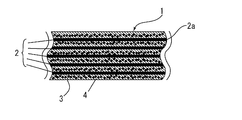
- FIG. 1 is a shaft
- 2 is a glass fiber bundle
- 2a is a glass fiber constituting it
- 3 is a carbon black
- 4 is a matrix resin.
- the distribution state of this carbon black can be confirmed by observing the cross section of the conductive shaft with an electron microscope, but usually, the compounding ratio of carbon black in the resin composition which is the material of the matrix resin is described later.
- FIG. 2 is a figure for a comparison, and shows a mode that carbon black does not become the above distribution states, but is aggregating.
- the glass fiber needs to be a continuous fiber from the viewpoint of strength and rigidity, and it is bundled as described above.
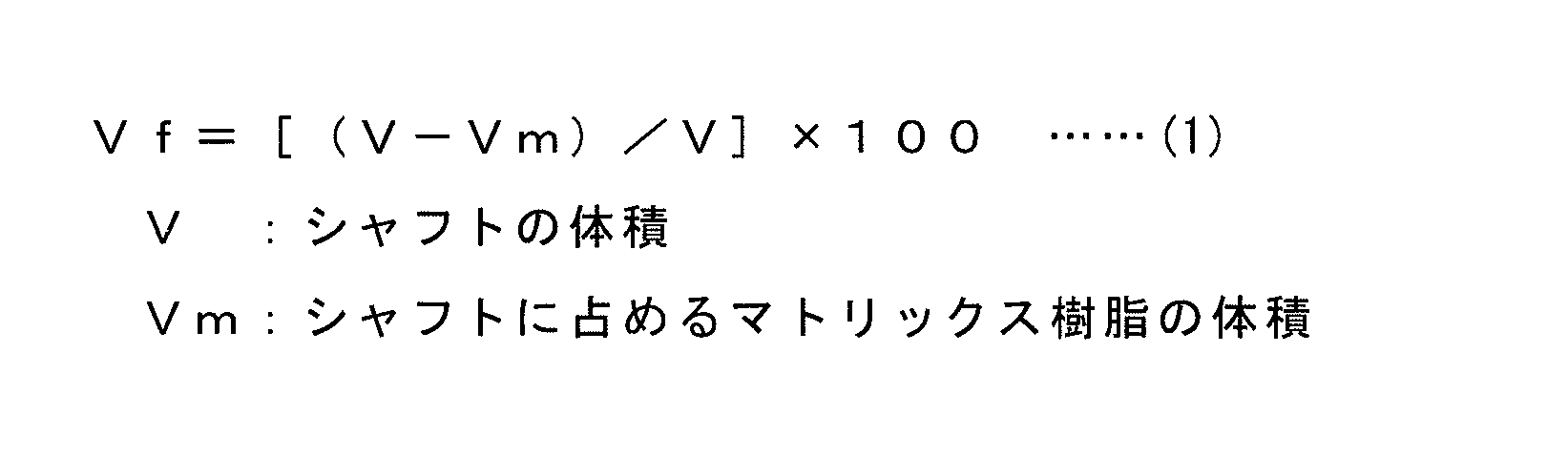
- the glass fiber content (Vf value) of the conductive shaft of the present invention which is determined by the following calculation formula (1), is preferably 40 to 70%, more preferably 55 to 65%. That is, if the Vf value is too small, molding shrinkage may be severe, resulting in a product having no surface smoothness. Conversely, if the Vf value is too large, the amount of resin may be small and conductivity may not be ensured. It is from.
- thermosetting resin (A) constituting the resin composition which is the material of the matrix resin examples include unsaturated polyester resin, vinyl ester resin, epoxy resin, phenol resin and the like. Be These may be used alone or in combination of two or more. Among them, unsaturated polyester resins are preferable from the viewpoint of adhesion to glass fibers.
- Examples of the curing agent (D) of the thermosetting resin (A) include unsaturated polyester resin and vinyl ester resin such as methyl ethyl ketone peroxide, acetylacetone peroxide, benzoyl peroxide, and tertiary butyl peroxy-2- Organic peroxides such as ethyl hexanoate, benzoyl peroxide, tertiary butyl perbenzoate and dicumyl peroxide are used, and for epoxy resins, bisphenol A, tetrabromobisphenol A, bisphenol S, bisphenol F, bis (bis ( 4-hydroxyphenyl) cyclohexane, bis (4-hydroxyphenyl) ethane, 1,3,3-trimethyl-1-m-hydroxyphenylindan-5-ol, 1,3,3-trimethyl-1-m-hydroxy Phenylindan-7-ol, 1,3,3-trimethyl-1-p-hydroxyphenylindan-6-ol, resorcinol, hydro
- diaminodiphenylmethane diaminodiphenylsulfone, diaminodiphenyl ether, phenylenediamine, diaminodicyclohexylmethane, xylylenediamine, toluenediamine, diaminodicyclocyclohexane, dichloro-diaminodiphenylmethane (including isomers)
- Polyamine compounds such as ethylene diamine and hexamethylene diamine, dicyandiamide, tetramethyl guanidine, active hydrogen-containing compounds capable of reacting with epoxy groups, etc. are used.
- the phenol resin, hexamethylene tetramine, melamine and methylol urea, or the like is used. These may be used alone or in combination of two or more.
- the proportion of the curing agent (D) in the resin composition is preferably in the range of 0.5 to 15 parts by weight, more preferably 100 parts by weight of the thermosetting resin (A), from the viewpoint of its curability. Is in the range of 1 to 10 parts by weight.
- the carbon black (B) used together with the thermosetting resin (A) has an average particle size (primary particle size) of preferably 18 to 122 nm, more preferably 27 to 43 nm, from the viewpoint of resin wettability. Is used. Further, the carbon black (B), from the viewpoint of electrical conductivity (electrical path route formation), the DBP oil absorption is preferably 42 ⁇ 495m 2 / g, more preferably those of 160 ⁇ 360m 2 / g used . The DBP oil absorption amount is defined in JIS K 6217. Specific examples of the carbon black as described above include acetylene black, ketjen black and the like. These may be used alone or in combination of two or more. Among them, acetylene black is preferable from the viewpoint of the wettability of the resin and the conductivity (electrical path formation).
- the proportion of carbon black (B) in the above resin composition is preferably in the range of 5 to 15 parts by weight with respect to 100 parts by weight of the thermosetting resin (A). That is, when the blending amount of the carbon black (B) is too small, sufficient conductivity can not be obtained, and conversely, when the blending amount of the carbon black (B) is too large, the viscosity of the resin composition becomes high. This is because the resin composition is not fully impregnated into the fiber bundle, and a decrease in formability and an adverse effect on the conductivity are observed.
- the dispersing agent (C) used with the said thermosetting resin (A) and carbon black (B) As a specific dispersing agent (C) used with the said thermosetting resin (A) and carbon black (B), the dispersing agent which has a basic functional group is used.
- the “dispersant” in the present invention improves the dispersibility in the thermosetting resin (A) by adsorbing to the surface of the carbon black (B), and re-removing the carbon black (B) with time. What suppresses aggregation is used.
- As a basic functional group in the said dispersing agent since it is easy to act on carbon black (B), an amino group, an amine group etc. are mention
- the dispersant (C) further has a structure having an affinity to the thermosetting resin (A) from the viewpoint of further enhancing the dispersion stability of the carbon black (B).
- structure having an affinity to the thermosetting resin (A) differs depending on the type of the thermosetting resin (A), and, for example, an unsaturated polyester resin as the thermosetting resin (A) And vinyl ester resins, polymeric dispersants such as boric acid esters, alkyl ammonium salts of polycarboxylic acids, unsaturated polycarboxylic acid polymers, unsaturated fatty acid polyamine amides and acidic esters as the above-mentioned dispersant (C) Use one that has When an epoxy resin and a phenol resin are used as the thermosetting resin (A), an alkyl ammonium salt of a polycarboxylic acid, an unsaturated polycarboxylic acid polymer, an unsaturated fatty acid polyamine amide, and the like are used as the
- the dispersant (C) does not have a structure having an affinity to the thermosetting resin (A), it has a structure having an affinity to the thermosetting resin (A) separately.
- a dispersant dispersant not corresponding to (C)
- the same effect disersion stabilizing effect of carbon black (B)
- this dispersant is used, its ratio is preferably in the range of 1.45 to 3.78 parts by weight with respect to 100 parts by weight of the thermosetting resin (A).
- the commercially available dispersant (C) includes, for example, BYK-9076 (alkyl ammonium salt) manufactured by BYK, and SOLSPERSE 5000 (copper phthalocyanine sulfonic acid ammonium salt) manufactured by Nippon Lubrizol.
- thermosetting resin (A) examples of commercially available dispersants include SOLSPERSE 88000 manufactured by Nippon Lubrizol Corporation.
- the proportion of the dispersant (C) in the resin composition is preferably in the range of 5 to 15 parts by weight with respect to 100 parts by weight of the thermosetting resin (A), when used alone.
- the proportion of the dispersant (C) is 100 wt% of the thermosetting resin (A) It is preferably in the range of 1.45 to 3.78 parts by weight with respect to parts. That is, when the compounding amount of the dispersant (C) is too small, the viscosity of the resin composition becomes high, and sufficient dispersion stability of the carbon black (B) can not be obtained, and desired conductivity can not be expressed.
- a curing (crosslinking) accelerator if necessary, a curing (crosslinking) accelerator, a curing (crosslinking) acceleration assistant, an assistant, a plasticizer, an antiaging agent, an antishrinkage agent, an antiozonant, an antifoaming agent Agents, anti-sagging agents, organic solvents, inorganic fillers (talc, mica, calcium carbonate, kaolin, wollastonite, milled fiber) and the like may be added as appropriate.
- the conductive shaft of the present invention is produced, for example, as follows.
- the resin composition is impregnated with the continuous glass fiber, and then drawn into a mold and thermally cured, and the resulting long fiber-reinforced resin molded product is cut into a predetermined length.
- a non-woven fabric materials include polyester, glass and aramid
- the resin composition used for the above-mentioned impregnation treatment with a three-roll mill, since the aggregation of carbon black is further eliminated and the conductivity of the obtained conductive shaft can be further enhanced.
- the above-mentioned kneading treatment is carried out before adding the curing agent, and the kneading treatment is carried out again after adding the curing agent, but the kneading at this time may be carried out by hand stirring or feathering since the curing agent may be mixed into the resin composition.
- any treatment may be used. Among these, feather agitation is simple and preferable.
- the viscosity of the resin composition used for the above-mentioned impregnation treatment be in the range of 0.5 to 60 Pa ⁇ s, because the above special manufacturing method can be favorably performed.
- the said viscosity is measured before adding a hardening
- thermosetting of the above-mentioned impregnated resin composition in the mold is carried out by heat treatment at 100 to 160 ° C. for about 1 to 15 minutes.
- a long fiber-reinforced resin molded product obtained by heat curing in the above-mentioned mold is cut into a predetermined length by a cutting machine or the like to form a target conductive shaft.
- the conductive coating layer which consists of metal plating, metal powder, or a graphite suitably on the surface of the said shaft. That is, when the conductive coating layer is formed as described above, the possibility of the continuous glass fiber being exposed on the surface of the shaft is eliminated, the conductivity of the shaft surface is easily developed, and the bending rigidity of the shaft is improved. For it will also be. Moreover, the carbon black amount of the resin composition used for the impregnation process of the continuous glass fiber at the time of shaft preparation can be suppressed more by supplementing the electroconductivity of a shaft by the said conductive coating layer.
- the conductive coating layer may be formed only on the outer peripheral surface (side surface) of the shaft, but it is preferable that the conductive coating layer is also formed on the end surface of the shaft, that is, the cut surface of the shaft. That is, when the conductive coating layer is also formed on the surface of the shaft end as described above, the conductivity between the end of the shaft and the outer peripheral surface is well expressed.
- the above-mentioned shaft surface is the meaning including both a shaft peripheral surface and a shaft end surface.
- the conductive coating layer When the conductive coating layer is formed by metal plating, it can be formed, for example, by applying electrolytic plating or electroless plating such as zinc nickel plating or nickel plating to the shaft surface according to a conventional method.
- the conductive coating layer is formed of metal powder or graphite, for example, a coating liquid in which metal powder or graphite powder made of SUS, aluminum or the like is dispersed in an organic solvent is applied to the shaft surface and dried. By performing this, the application of the conductive coating layer can be performed.
- the conductive coating layer may be formed as described above with a coating liquid in which the metal powder and the graphite powder are mixed and dispersed.
- the coating liquid may contain a resin binder such as urethane, epoxy, acryl or polyester as appropriate from the viewpoint of enhancing the coating film strength, but in terms of conductivity, such a resin binder may be used. It is preferable not to contain it.
- the surface of the shaft before the coating may be roughened in advance by etching to improve the fixability of the conductive coating layer.
- the etching treatment is performed by chemical treatment with an alkaline solution, hydrofluoric acid solution or the like, or physical treatment with a wet blast or the like.
- the conductive shaft of the present invention obtained as described above sufficiently exhibits the function as a shaft of a conductive roll for OA equipment that the electric resistance value is less than 1 ⁇ 10 6 ⁇ . Because it can be
- the conductive roll for OA equipment which uses the conductive shaft of the present invention as a shaft has excellent function as a conductive roll for OA equipment (in particular, charging roll and developing roll) due to the performance of the shaft. It can be demonstrated.
- the conductive shaft of the present invention exhibits excellent performance as a shaft of a roll for OA equipment such as a toner supply roll, a paper feed roll, a transfer roll, a cleaning roll, etc., in addition to the charging roll and the developing roll.
- a toner supply roll such as a toner supply roll, a paper feed roll, a transfer roll, a cleaning roll, etc.
- the conductive shaft of the present invention can be used as a shaft of industrial rolls such as a dustproof roll and an engraving roll, and also as a structural member of various products.
- thermosetting resin (A1) Unsaturated polyester resin (Yupika 3140, manufactured by Japan Yupika Co., Ltd.)
- Dispersant (C4) (for Comparative Example) Copolymer having acid group (BYK-W9010, manufactured by BYK)
- Dispersant (C5) for Comparative Example
- Block copolymer of spherical structure (DISPERBYK-2155, manufactured by BYK)
- thermosetting resin and the dispersant were mixed and subjected to feather stirring, carbon black was added and the mixture was kneaded with a three-roll mill. Thereafter, a curing agent was added and the mixture was stirred to prepare a resin composition.
- the mixing ratio of each component and the three-roll gap at the time of the kneading were as shown in Tables 1 and 2 below.
- the continuous glass fibers are bundled, they are drawn into a crucible containing the resin composition prepared above, impregnated with the continuous glass fibers into the resin composition, and then drawn into a mold and thermally cured.
- the long fiber-reinforced resin molded product was cut to prepare a shaft having a diameter of 6 mm and a length of 300 mm.
- the shaft was produced so that the glass fiber content (Vf value) of the shaft calculated
- Viscosity measurement The viscosity (viscosity before adding the curing agent) of the resin composition after being kneaded with a three-roll mill was measured under the following conditions. -Device: Toki Sangyo Co., VISCOMETER TVB-10 (TVR)-Rotor type: H7 ⁇ Number of revolutions: 60 rpm Measurement environment: room temperature (28 ° C to 35 ° C)
- the electrical resistance value differs in numerical value depending on the shape (cross-sectional area and length) to be evaluated. Therefore, the shape of the shaft was standardized to a diameter of 6 mm and a length of 300 mm, and the electric resistance value was measured using a tester (MODEL 3021, manufactured by HIOKI). The measurement was performed by placing the measuring needle on the end cross section of the shaft having the above shape. Then, what its electrical resistance was less than 1 ⁇ 10 3 ⁇ ⁇ , what had been less than 1 ⁇ 10 3 Omega least 1 ⁇ 10 6 ⁇ ⁇ , was evaluated as ⁇ least 1 ⁇ 10 6 Omega .
- the shafts of Examples 1 to 9 have lower electric resistance values and superior conductivity as compared with the shafts of Comparative Examples.
- the compounding quantity of carbon black was further raised in the comparative example, the rapid rise (60 Pa.s or more) of the viscosity of a resin composition is seen, and a shaft is applied using the shaping
- Example 10 A conductive coating layer was formed on the entire surface of the shaft produced in the same manner as in Example 1 by the following coating treatment 1.
- Pd catalyst-imparting agent OPC-50 inducer, manufactured by Okuno Pharmaceutical Industries Co., Ltd.
- Example 11 The conductive coating layer was formed on the entire surface of the shaft produced in the same manner as in Example 4 by the above-mentioned coating treatment 1.
- Example 12 The conductive coating layer was formed on the entire surface of the shaft produced in the same manner as in Example 6 by the above-mentioned coating treatment 1.
- Example 13 A conductive coating layer was formed on the entire surface of the shaft produced in the same manner as in Example 6 by the following coating treatment 2.
- coating treatment 2 Spray the spray agent (graphite spray, made by Fine Chemical Japan Co., Ltd.) in which graphite powder is dispersed in organic solvent such as isopropanol and dimethyl ether on the entire surface of the shaft, dry it at room temperature for about 1 hour, and further dry at 60 ° C. To form a conductive coating layer.
- Example 14 A conductive coating layer was formed on the entire surface of the shaft produced in the same manner as in Example 6 by the following coating treatment 3.
- coating treatment 3 Spray the spray agent (Stainless steel spray, made by Fine Chemical Japan Co., Ltd.) in which SUS powder is dispersed in organic solvent such as toluene and dimethyl ether on the whole surface of the shaft, dry it at room temperature for about 1 hour, and further dry at 60 ° C. To form a conductive coating layer.
- spray the spray agent Stainless steel spray, made by Fine Chemical Japan Co., Ltd.
- organic solvent such as toluene and dimethyl ether
- Example 15 A conductive coating layer was formed on the entire surface of the shaft produced in the same manner as in Example 6 by the following coating treatment 4.
- coating treatment 4 Spray a spray agent (fine heat reflector, made by Fine Chemical Japan Co., Ltd.) in which aluminum powder is dispersed in an organic solvent such as toluene or dimethyl ether over the entire surface of the shaft and dry at room temperature for about 1 hour. To form a conductive coating layer.
- Example 16 A conductive coating layer was formed on the entire surface of the shaft produced in the same manner as in Example 6 by the following coating treatment 5.
- coating treatment 5 After spraying a spray agent (non-seeds, made by Fine Chemical Japan Co., Ltd.) in which graphite powder and aluminum powder are mixed and dispersed in an organic solvent such as butane or propanol on the entire surface of the shaft and drying at room temperature for about 1 hour It dried at ° C and formed a conductive coating layer.
- a spray agent non-seeds, made by Fine Chemical Japan Co., Ltd.
- the flexural modulus of the shaft was measured according to the following criteria, while the flexural modulus of Example 1 was 43 GPa, the flexural modulus of Example 10 was 46 GPa, Example 4 The bending elastic modulus of Example 11 is 46 GPa, while the bending elastic modulus of Example 12 is 52 GPa, while the bending elastic modulus of Example 12 is 43 GPa. It was 56 GPa.
- the formation of the conductive coating layer was found to have the effect of improving the flexural modulus.
- the conductive shaft of the present invention is lightweight, high in strength, excellent in conductivity, and inexpensive. Therefore, although it is preferably used as a shaft of a conductive roll for OA equipment, a shaft of a roll for OA equipment which is not required to have conductivity, a shaft of an industrial roll such as a dustproof roll, an engraving roll, etc. It can also be used as a structural member of various products.
Landscapes
- Physics & Mathematics (AREA)
- General Physics & Mathematics (AREA)
- Chemical & Material Sciences (AREA)
- Engineering & Computer Science (AREA)
- Dispersion Chemistry (AREA)
- Spectroscopy & Molecular Physics (AREA)
- Plasma & Fusion (AREA)
- Composite Materials (AREA)
- Mechanical Engineering (AREA)
- Rolls And Other Rotary Bodies (AREA)
- Dry Development In Electrophotography (AREA)
- Electrophotography Configuration And Component (AREA)
- Electrostatic Charge, Transfer And Separation In Electrography (AREA)
- Shafts, Cranks, Connecting Bars, And Related Bearings (AREA)
Abstract
シャフトの長手方向に平行に連続ガラス繊維束が埋設された繊維強化樹脂製のシャフトであって、そのマトリックス樹脂が、下記の(A)を主成分とし下記の(B)~(D)成分を含有する樹脂組成物からなり、上記(B)成分が、粒子状でかつ連続ガラス繊維束を構成する連続ガラス繊維に沿って分布している。このため、軽量で、強度が高く、導電性に優れ、しかも安価である、導電性シャフトおよびそれを用いたOA機器用導電性ロール、並びに導電性シャフトの製法を提供することができる。 (A)熱硬化性樹脂。 (B)カーボンブラック。 (C)塩基性官能基を有する分散剤。 (D)(A)成分の硬化剤。
Description
本発明は、繊維強化樹脂(FRP)からなる導電性シャフトおよびそれを用いたOA機器用導電性ロール、並びに上記導電性シャフトの製法に関するものである。
電子写真複写機、プリンター、ファクシミリ等のOA(オフィス・オートメイション:Office Automation)機器用の、導電性ロール(帯電ロール、現像ロール等)には、通常、鉄等の金属製の軸体(シャフト)が用いられる。また、上記軸体には、通常、腐食防止のためのめっき処理が施されている。上記のように導電性ロールに金属製の軸体が用いられる理由は、高精度の加工性や、帯電機構に伴う導電性が要求されるからである。
しかしながら、シャフトに施しているめっきは、輸送時の軸体同士の擦れや研磨粉による擦れなどで剥がれやすく、その結果、シャフトの腐食に至る懸念がある。
また、輸送しやすいよう、シャフトの軽量化が求められており、さらには、空輸に際し飛行機の計器に悪影響を与えないよう、シャフトの非磁性化も求められている。さらに、めっきに微量含まれる環境負荷物質をできるだけ少なくしたいといった環境面の要望もある。
以上のことから、近年、金属製シャフトに代えて、樹脂製シャフトを軸体に用いた導電性ロールが提案されている(特許文献1参照)。すなわち、樹脂製であるため、重金属などは含まず、錆びることもなく、しかも軽量であることから、上記金属製シャフトの問題を解消することが可能である。
しかしながら、樹脂製シャフトは、強度や剛性の点で問題があり、しかも金属性シャフトと比較して導電性が低く、電気ロスが大きいことから、導電性ロールの軸体としての実用に耐えないといった問題がある。また、樹脂製シャフトに導電性を付与する場合、通常、その材料である樹脂組成物にカーボンブラック等の導電性フィラーを添加して導電性を高くする手法が用いられるが、導電性を高めるためにその添加量を多くすると、樹脂組成物の粘度が増加して成形困難となるといった問題が生じる。特に、特許文献1に開示のシャフトのように射出成形によって製造する場合、カーボンブラックを多量に添加すると、射出成形が困難なほど樹脂組成物の粘度が極端に上昇することから、カーボンブラックの多量添加による導電性の発現は困難である。また、カーボンブラックは、導電性フィラーのなかでも安価なため、コストメリットが高いが、他の導電性フィラーと比較して粒子が小さく表面積が大きいことから凝集・再凝集が生じやすく、結果、導電性が発現しにくいといった問題もある。
そこで、本発明者らは、補強材として、導電性を有する炭素繊維(CF)のみを用いた、繊維強化樹脂(FRP)製のシャフトを検討してみた。しかしながら、炭素繊維(CF)は非常にコストが高く、そのため、製品単価に大きく影響するといった問題がある。
本発明は、このような事情に鑑みなされたもので、軽量で、強度が高く、導電性に優れ、しかも安価である、導電性シャフトおよびそれを用いたOA機器用導電性ロール、並びに導電性シャフトの製法の提供をその目的とする。
上記の目的を達成するため、本発明は、シャフトの長手方向に平行に連続ガラス繊維束が埋設された繊維強化樹脂製のシャフトであって、そのマトリックス樹脂が、下記の(A)を主成分とし下記の(B)~(D)成分を含有する樹脂組成物からなり、上記(B)成分が、粒子状でかつ連続ガラス繊維束を構成する連続ガラス繊維に沿って分布している導電性シャフトを第一の要旨とし、上記導電性シャフトを軸体とするOA機器用導電性ロールを第二の要旨とする。
(A)熱硬化性樹脂。
(B)カーボンブラック。
(C)塩基性官能基を有する分散剤。
(D)(A)成分の硬化剤。
(A)熱硬化性樹脂。
(B)カーボンブラック。
(C)塩基性官能基を有する分散剤。
(D)(A)成分の硬化剤。
また、本発明は、上記導電性シャフトの製法であって、連続ガラス繊維を束ねた状態で、下記の(A)を主成分とし下記の(B)~(D)成分を含有する樹脂組成物の入った漕に引き込み、連続ガラス繊維を樹脂組成物に含浸させた後、金型に引き込み熱硬化させ、それにより得られた長尺の繊維強化樹脂成形品を、所定の長さに切断する導電性シャフトの製法を第三の要旨とする。
(A)熱硬化性樹脂。
(B)カーボンブラック。
(C)塩基性官能基を有する分散剤。
(D)(A)成分の硬化剤。
(A)熱硬化性樹脂。
(B)カーボンブラック。
(C)塩基性官能基を有する分散剤。
(D)(A)成分の硬化剤。
すなわち、本発明者らは、前記課題を解決するため鋭意研究を重ねた。その研究の過程で、本発明者らは、シャフトを繊維強化樹脂製にし、その補強材となる繊維に、炭素繊維(CF)よりもコストメリットの高いガラス繊維(GF)からなる連続繊維束を用い、シャフトの長手方向に平行に連続ガラス繊維束が埋設されるようにし、かつ、導電性付与のため、そのマトリックス樹脂中にカーボンブラックを含有させることを検討した。しかしながら、カーボンブラックを用いた場合、先に述べたような成形性や導電性付与に関する問題を解決する必要がある。そこで、本発明者らが、さらに研究を重ね、マトリックス樹脂組成物を、熱硬化性樹脂(A)を主成分とし、塩基性官能基を有する分散剤(C)を含有するものとしたところ、上記分散剤(C)の塩基性官能基がカーボンブラック(B)の酸性官能基と相互作用し、カーボンブラック(B)の分散性が改善されて、カーボンブラック(B)が連続ガラス繊維束の間に入り込んで配列するようになることを突き止めた。これにより、カーボンブラック(B)が、粒子状でかつ連続ガラス繊維束を構成する連続ガラス繊維に沿って分布するようになり、少ないカーボンブラック量で組成物の粘度を上げずに電気パスルートをつくることができ、その結果、所期の目的が達成できる導電性シャフトが得られることを見いだし、本発明に到達した。
なお、上記のように少ないカーボンブラック量で電気パスルートをつくるには、従来のような射出成形では困難である。そこで、連続ガラス繊維を束ねた状態で、前記マトリックス樹脂組成物の入った漕に引き込み、連続ガラス繊維を樹脂組成物に含浸させた後、金型に引き込み熱硬化させ、それにより得られた長尺の繊維強化樹脂成形品を、所定の長さに切断するといった特殊な製法を適用したところ、上記の問題は解消され、先に述べたような特殊な導電性シャフトを良好に製造することができるようになることを、本発明者らは突き止めた。
以上のように、本発明の導電性シャフトは、シャフトの長手方向に平行に連続ガラス繊維束が埋設された繊維強化樹脂製のシャフトであって、そのマトリックス樹脂が、熱硬化性樹脂(A)を主成分とし、カーボンブラック(B)、特定の分散剤(C)および硬化剤(D)を含有する樹脂組成物からなり、上記カーボンブラック(B)が、粒子状でかつ連続ガラス繊維束を構成する連続ガラス繊維に沿って分布している。そのため、軽量で、強度が高く、導電性に優れ、しかも安価な導電性シャフトとすることができる。また、上記導電性シャフトを用いたOA機器用導電性ロールは、従来の金属製シャフトを用いたものと同様、優れたロール性能を発現するとともに、軽量化等の、上記導電性シャフトを用いたことによる作用効果を得ることができる。
また、連続ガラス繊維を束ねた状態で、上記樹脂組成物の入った漕に引き込み、連続ガラス繊維を樹脂組成物に含浸させた後、金型に引き込み熱硬化させ、それにより得られた長尺の繊維強化樹脂成形品を、所定の長さに切断するといった特殊な製法により、少ないカーボンブラック量で電気パスルートをつくることができ、本発明の導電性シャフトを良好に製造することができる。
つぎに、本発明の実施の形態を詳しく説明する。
本発明の導電性シャフトは、先に述べたように、シャフトの長手方向に平行に連続ガラス繊維束が埋設された繊維強化樹脂製のシャフトであって、そのマトリックス樹脂が、熱硬化性樹脂(A)を主成分とし、カーボンブラック(B)、特定の分散剤(C)および硬化剤(D)を含有する樹脂組成物からなり、上記カーボンブラック(B)が、粒子状でかつ連続ガラス繊維束を構成する連続ガラス繊維に沿って分布している。ここで、上記樹脂組成物の「主成分」とは、その組成物全体の特性に大きな影響を与えるもののことであり、本発明においては、全体の50重量%以上を意味する。また、「上記カーボンブラック(B)が、粒子状でかつ連続ガラス繊維束を構成する連続ガラス繊維に沿って分布している。」とは、カーボンブラックの凝集がみられず、連続ガラス繊維に沿ってカーボンブラックによる電気パスルートができており、それによりシャフトの導電性が確保された状態を意味する。これを模式的に示すと、図1に示すようになる。図において、1はシャフト、2はガラス繊維束、2aはそれを構成するガラス繊維、3はカーボンブラック、4はマトリックス樹脂である。このカーボンブラックの分布状態は、導電性シャフトの断面を電子顕微鏡観察することにより確認することが可能であるが、通常、上記マトリックス樹脂の材料である樹脂組成物中のカーボンブラックの配合割合が後記に示す範囲内で、かつその導電性シャフトの電気抵抗値が後記のように低い値を示すものであれば、カーボンブラックが上記のような分布状態となっているとみなすことができる。なお、図2は、比較用の図であり、カーボンブラックが上記のような分布状態となっておらず凝集している様子を示すものである。
本発明の導電性シャフトにおいて、ガラス繊維は、上記のように、強度や剛性の観点から連続繊維である必要があり、それが、上記のように束になっている。なお、以下の計算式(1)で求められる、本発明の導電性シャフトにおけるガラス繊維含有率(Vf値)は、好ましくは40~70%であり、より好ましくは55~65%である。すなわち、Vf値が少な過ぎると、成形収縮がひどく、表面平滑性のない製品となるおそれがあり、逆にVf値が多過ぎると、樹脂量が少なくなり、導電性が確保できなくなるおそれがあるからである。

また、本発明の導電性シャフトにおいて、前記マトリックス樹脂の材料である樹脂組成物を構成する熱硬化性樹脂(A)としては、不飽和ポリエステル樹脂、ビニルエステル樹脂、エポキシ樹脂、フェノール樹脂等があげられる。これらは単独でもしくは二種以上併せて用いられる。なかでも、ガラス繊維との密着性の観点から、不飽和ポリエステル樹脂が好ましい。
上記熱硬化性樹脂(A)の硬化剤(D)としては、例えば、不飽和ポリエステル樹脂およびビニルエステル樹脂には、メチルエチルケトンパーオキサイド、アセチルアセトンパーオキサイド、ベンゾイルパーオキサイド、ターシャリーブチルパーオキシ-2-エチルヘキサノエート、ベンゾイルパーオキサイド、ターシャリーブチルパーベンゾエート、ジクミルパーオキサイド等の有機過酸化物が用いられ、エポキシ樹脂には、ビスフェノールA、テトラブロモビスフェノールA、ビスフェノールS、ビスフェノールF、ビス(4-ヒドロキシフェニル)シクロヘキサン、ビス(4-ヒドロキシフェニル)エタン、1,3,3-トリメチル-1-m-ヒドロキシフェニルインダン-5-オール、1,3,3-トリメチル-1-m-ヒドロキシフェニルインダン-7-オール、1,3,3-トリメチル-1-p-ヒドロキシフェニルインダン-6-オール、レゾルシン、ハイドロキノン、カテコール、ナジク酸,マレイン酸,フタル酸,メチル-テトラヒドロフタル酸,メチルナジク酸等のポリカルボン酸とその無水物、ジアミノジフェニルメタン、ジアミノジフェニルスルホン、ジアミノジフェニルエーテル、フェニレンジアミン、ジアミノジシクロヘキシルメタン、キシリレンジアミン、トルエンジアミン、ジアミノジシクロシクロヘキサン、ジクロロ-ジアミノジフェニルメタン(異性体を含む)、エチレンジアミン、ヘキサメチレンジアミン等のポリアミン化合物、ジシアンジアミド、テトラメチルグアニジン、エポキシ基と反応可能な活性水素含有化合物等が用いられ、フェノール樹脂には、ヘキサメチレンテトラミン、メチロールメラミンおよびメチロール尿素等が用いられる。これらは単独でもしくは二種以上併せて用いられる。上記樹脂組成物における硬化剤(D)の割合は、その硬化性の観点から、熱硬化性樹脂(A)100重量部に対し、好ましくは0.5~15重量部の範囲であり、より好ましくは1~10重量部の範囲である。
上記熱硬化性樹脂(A)とともに用いられるカーボンブラック(B)としては、樹脂の濡れ性の観点から、その平均粒径(一次粒子径)が、好ましくは18~122nm、より好ましくは27~43nmのものが用いられる。また、上記カーボンブラック(B)は、導電性(電気パスルート形成)の観点から、そのDBP吸油量が、好ましくは42~495m2/g、より好ましくは160~360m2/gのものが用いられる。なお、上記DBP吸油量は、JIS K 6217に規定されており、上記のようなカーボンブラックは、具体的には、アセチレンブラック、ケッチェンブラック等があげられる。これらは単独でもしくは二種以上併せて用いられる。なかでも、樹脂の濡れ性および導電性(電気パスルート形成)の観点からアセチレンブラックが好ましい。
上記樹脂組成物におけるカーボンブラック(B)の割合は、熱硬化性樹脂(A)100重量部に対し、好ましくは5~15重量部の範囲である。すなわち、上記カーボンブラック(B)の配合量が少なすぎると、充分な導電性が得られず、逆に上記カーボンブラック(B)の配合量が多すぎると、樹脂組成物の粘度が高くなり、繊維束中に樹脂組成物が含浸しきらず、成形性の低下や導電性への悪影響がみられるからである。
上記熱硬化性樹脂(A)、カーボンブラック(B)とともに用いられる、特定の分散剤(C)としては、塩基性官能基を有する分散剤が用いられる。ここで、本発明における「分散剤」とは、カーボンブラック(B)の表面に吸着することで熱硬化性樹脂(A)への分散性を向上させると共に、経時によるカーボンブラック(B)の再凝集を抑制するものが用いられる。上記分散剤における塩基性官能基としては、カーボンブラック(B)に作用しやすいことから、例えば、アミノ基、アミン基等があげられる。
また、上記分散剤(C)が、さらに熱硬化性樹脂(A)と親和性のある構造を有することが、カーボンブラック(B)の分散安定性をより高める観点から好ましい。なお、上記「熱硬化性樹脂(A)と親和性のある構造」とは、熱硬化性樹脂(A)の種類によって異なるものであり、例えば、熱硬化性樹脂(A)として不飽和ポリエステル樹脂およびビニルエステル樹脂を用いるときは、上記分散剤(C)として、ホウ酸エステル、ポリカルボン酸のアルキルアンモニウム塩、不飽和ポリカルボン酸ポリマー、不飽和脂肪酸ポリアミンアミドと酸性エステル等の高分子ポリマー成分を有するものを用いる。また、熱硬化性樹脂(A)としてエポキシ樹脂およびフェノール樹脂を用いるときは、上記分散剤(C)として、ポリカルボン酸のアルキルアンモニウム塩、不飽和ポリカルボン酸ポリマー、不飽和脂肪酸ポリアミンアミドと酸性エステル等の高分子ポリマー成分を有するものを用いる。
なお、上記分散剤(C)が、熱硬化性樹脂(A)と親和性のある構造を有さない場合であっても、別途、熱硬化性樹脂(A)と親和性のある構造を有する分散剤((C)に該当しない分散剤)を、上記分散剤(C)と併用することで、上記と同様の効果(カーボンブラック(B)の分散安定効果)を得ることができる。なお、この分散剤を用いる場合、その割合は、熱硬化性樹脂(A)100重量部に対し1.45~3.78重量部の範囲であることが好ましい。
そして、上記分散剤(C)は、市販品では、例えば、BYK社製のBYK-9076(アルキルアンモニウム塩)、日本ルーブリゾール社製のSOLSPERSE5000(銅フタロシアニンスルホン酸アンモニウム塩)等があげられる。
また、熱硬化性樹脂(A)と親和性のある構造を有するが塩基性官能基を有しない分散剤は、市販品では、例えば、日本ルーブリゾール社製のSOLSPERSE88000等があげられる。
前記樹脂組成物における上記分散剤(C)の割合は、単独で用いる場合は、熱硬化性樹脂(A)100重量部に対し5~15重量部の範囲であることが好ましいが、上記のように、熱硬化性樹脂(A)と親和性のある構造を有するが塩基性官能基を有しない分散剤と併用する場合、分散剤(C)の割合は、熱硬化性樹脂(A)100重量部に対し1.45~3.78重量部の範囲であることが好ましい。すなわち、上記分散剤(C)の配合量が少なすぎると、樹脂組成物の粘度が高くなりカーボンブラック(B)の充分な分散安定性が得られず、所望の導電性を発現できないからであり、逆に上記分散剤(C)の配合量が多すぎると、カーボンブラック(B)に作用しない余剰の分散剤が存在することとなり、繊維束に沿って分布する粒子状のカーボンブラック同士の間隔が広がり過ぎ、所望の導電性を発現できないからである。
なお、上記樹脂組成物には、必要に応じて、硬化(架橋)促進剤、硬化(架橋)促進助剤、助剤、可塑剤、老化防止剤、収縮防止剤、オゾン劣化防止剤、消泡剤、垂れ止め剤、有機溶剤、無機充填剤(タルク、マイカ、炭酸カルシウム、カオリン、ワラストナイト、ミルドファイバー)等を適宜添加してもよい。
つぎに、本発明の導電性シャフトは、例えば以下のようにして作製される。
すなわち、連続ガラス繊維を束ねた状態で、熱硬化性樹脂(A)を主成分とし、その硬化剤(D)、カーボンブラック(B)、および特定の分散剤(C)を含有する樹脂組成物の入った漕に引き込み、連続ガラス繊維を樹脂組成物に含浸させた後、金型に引き込み熱硬化させ、それにより得られた長尺の繊維強化樹脂成形品を、所定の長さに切断する。また、連続ガラス繊維を樹脂組成物に含浸させた後、金型に引き込む際に、繊維の表面への露出を抑えるために不織布(材質としては、ポリエステル系、ガラス系、アラミド系がある)を設定しても良い。このような特殊な製法により、少ないカーボンブラック量で電気パスルートをつくることができ、目的とする本発明の導電性シャフトを良好に製造することができる。
特に、上記含浸処理に用いる樹脂組成物を、三本ロールにより混練処理することが、カーボンブラックの凝集がより解消され、得られる導電性シャフトの導電性をより高めることができることから、好ましい。なお、上記混練処理は、硬化剤を加える前に行い、硬化剤を加えた後に再度混練を行うが、このときの混練は、硬化剤が樹脂組成物中に混ざればよいため、手撹拌、羽撹拌およびロールによる混練のうち、いずれかの処理で構わない。その中でも、羽撹拌が簡便で好ましい。
また、上記含浸処理に用いる樹脂組成物の粘度を、0.5~60Pa・sの範囲にすることが、上記特殊な製法を良好に行うことができることから、好ましい。なお、上記粘度は、硬化剤を添加する前に測定したものであり、JIS K 7117に準拠し、B型粘度計を用いて、温度:室温(28℃~35℃)で測定した値である。
上記含浸処理した樹脂組成物の、金型内での熱硬化は、100~160℃で、1~15分間程度の熱処理で行われる。
上記金型内での熱硬化により得られた長尺の繊維強化樹脂成形品は、切断機等により所定の長さに切断され、目的とする導電性シャフトとなる。
なお、上記一連の製法は、一般的な引抜成形機を用いて行うことも可能である。
また、上記シャフトの表面には、適宜、金属めっき、金属粉またはグラファイトからなる導電コーティング層を形成することが好ましい。すなわち、上記のように導電コーティング層を形成すると、シャフトの表面に連続ガラス繊維が露出するおそれが解消され、シャフト表面の導電性が発現しやすくなり、さらに、シャフトの曲げ剛性が向上するようにもなるからである。また、上記導電コーティング層によってシャフトの導電性を補うことにより、シャフト作製時における連続ガラス繊維の含浸処理に用いる樹脂組成物のカーボンブラック量をより抑えることができる。その結果、上記樹脂組成物の高粘度化を抑えることができ、シャフトの引抜成形がより行いやすくなるため、シャフトの生産性をより向上させることができる。なお、上記導電コーティング層は、シャフト外周面(側面)のみに対し形成されていてもよいが、シャフトの端部表面、つまりシャフトの切断面に対しても形成されていたほうがよい。すなわち、このようにシャフト端部表面にも導電コーティング層が形成されていると、シャフトの端部と外周面との間の導電性が良好に発現されるようになるからである。ところで、上記シャフト表面とは、シャフト外周面とシャフト端部表面との両方を含む趣旨である。
上記導電コーティング層を、金属めっきにより形成する場合、例えば、亜鉛ニッケルめっき,ニッケルめっきといった、電解めっきあるいは無電解めっきを、常法に従いシャフト表面に施すことにより、形成することができる。また、上記導電コーティング層を、金属粉やグラファイトにより形成する場合、例えば、SUS,アルミニウム等からなる金属粉やグラファイト粉末を有機溶媒に分散させた塗工液を、シャフト表面に塗工し、乾燥させることにより、上記導電コーティング層の施工を行うことができる。なお、上記金属粉とグラファイト粉末とを混合分散させた塗工液で、上記のように導電コーティング層を形成してもよい。また、上記塗工液には、塗膜強度を高める観点から、適宜、ウレタン、エポキシ、アクリル、ポリエステル等の樹脂バインダーを含有させてもよいが、導電性の点では、このような樹脂バインダーを含有させないほうが好ましい。また、上記コーティング前のシャフト表面を、予めエッチング処理により粗化し、上記導電コーティング層の定着性を高めるようにしてもよい。上記エッチング処理は、アルカリ溶液、ふっ酸溶液等による化学的処理や、ウェットブラスト等による物理的処理により行われる。
上記のようにして得られた本発明の導電性シャフトは、その電気抵抗値が1×10⁶Ω未満であることが、OA機器用導電性ロールの軸体としての機能を充分に発揮することができるため、好ましい。
そして、本発明の導電性シャフトを軸体とするOA機器用導電性ロールは、その軸体の性能に起因し、OA機器用導電性ロール(特に、帯電ロールや現像ロール)として優れた機能を発揮することができる。
なお、本発明の導電性シャフトは、帯電ロールや現像ロールの他、トナー供給ロール、給紙ロール、転写ロール、クリーニングロール等のOA機器用ロールの軸体としても、優れた性能を発揮することができる。その他にも、本発明の導電性シャフトは、防塵ロール、彫刻ロールなど産業用ロールの軸体や、さらに、各種製品の構造部材等としても用いることができる。
つぎに、実施例について比較例と併せて説明する。ただし、本発明は、その要旨を超えない限り、これら実施例に限定されるものではない。
まず、実施例および比較例に先立ち、下記に示す材料を準備した。
〔熱硬化性樹脂(A1)〕
不飽和ポリエステル樹脂(ユピカ3140、日本ユピカ社製)
不飽和ポリエステル樹脂(ユピカ3140、日本ユピカ社製)
〔カーボンブラック(B1)〕
デンカブラック(平均粒径35nm、DBP吸油量160ml/100g)、デンカ社製
デンカブラック(平均粒径35nm、DBP吸油量160ml/100g)、デンカ社製
〔カーボンブラック(B2)〕
シーストTA(平均粒径122nm、DBP吸油量42ml/100g)、東海カーボン社製
シーストTA(平均粒径122nm、DBP吸油量42ml/100g)、東海カーボン社製
〔分散剤(C1)〕
アルキルアンモニウム塩(BYK-9076、BYK社製)
アルキルアンモニウム塩(BYK-9076、BYK社製)
〔分散剤(C2)〕
銅フタロシアニンスルホン酸アンモニウム塩(SOLSPERSE5000、日本ルーブリゾール社製)
銅フタロシアニンスルホン酸アンモニウム塩(SOLSPERSE5000、日本ルーブリゾール社製)
〔分散剤(C3)〕
SOLSPERSE88000、日本ルーブリゾール社製
SOLSPERSE88000、日本ルーブリゾール社製
〔分散剤(C4)(比較例用)〕
酸基をもつコポリマー(BYK-W9010、BYK社製)
酸基をもつコポリマー(BYK-W9010、BYK社製)
〔分散剤(C5)(比較例用)〕
球状構造のブロック共重合体(DISPERBYK-2155、BYK社製)
球状構造のブロック共重合体(DISPERBYK-2155、BYK社製)
〔硬化剤(D1)〕
パーロイルTCP、日油社製
パーロイルTCP、日油社製
[実施例1~9、比較例1~3]
上記熱硬化性樹脂と分散剤とを配合し、羽撹拌を行った後、カーボンブラックを加え、三本ロールにて混練した。その後、硬化剤を加え羽撹拌を行い、樹脂組成物を調製した。なお、上記各成分の配合割合、上記混練時の三本ロール間隙は、後記の表1および表2に示す通りとした。
上記熱硬化性樹脂と分散剤とを配合し、羽撹拌を行った後、カーボンブラックを加え、三本ロールにて混練した。その後、硬化剤を加え羽撹拌を行い、樹脂組成物を調製した。なお、上記各成分の配合割合、上記混練時の三本ロール間隙は、後記の表1および表2に示す通りとした。
続いて、連続ガラス繊維を束ねた状態で、上記調製の樹脂組成物の入った漕に引き込み、連続ガラス繊維を樹脂組成物に含浸させた後、金型に引き込み熱硬化させ、それにより得られた長尺の繊維強化樹脂成形品を切断し、直径6mm、長さ300mmのシャフトを作製した。なお、以下の計算式(1)で求められるシャフトのガラス繊維含有率(Vf値)が、後記の表1および表2に示す通りとなるようシャフトを作製した。
このようにして得られた実施例および比較例のシャフトに関し、下記の基準に従い各特性を測定し、評価を行った。その結果を、後記の表1および表2に併せて示した。
〔粘度測定〕
三本ロールにて混練した後の樹脂組成物の粘度(硬化剤を添加する前の粘度)を下記の条件で測定した。
・装置:TOKI SANGYO社製、VISCOMETER TVB-10(TVR)・ローター種:H7
・回転数:60rpm
・測定環境:室温(28℃~35℃)
三本ロールにて混練した後の樹脂組成物の粘度(硬化剤を添加する前の粘度)を下記の条件で測定した。
・装置:TOKI SANGYO社製、VISCOMETER TVB-10(TVR)・ローター種:H7
・回転数:60rpm
・測定環境:室温(28℃~35℃)
〔電気抵抗値測定〕
電気抵抗値は、評価対象の形状(断面積と長さ)により数値が異なる。そのため、シャフトの形状を、直径6mm、長さ300mmに統一して、その電気抵抗値を、テスター(MODEL3021、HIOKI社製)を用いて測定した。測定は、上記形状のシャフトの端部断面に計測針を当てて測定を行った。そして、その電気抵抗値が1×10³Ω未満であったものを◎、1×10³Ω以上1×10⁶Ω未満であったものを○、1×10⁶Ω以上を×と評価した。
電気抵抗値は、評価対象の形状(断面積と長さ)により数値が異なる。そのため、シャフトの形状を、直径6mm、長さ300mmに統一して、その電気抵抗値を、テスター(MODEL3021、HIOKI社製)を用いて測定した。測定は、上記形状のシャフトの端部断面に計測針を当てて測定を行った。そして、その電気抵抗値が1×10³Ω未満であったものを◎、1×10³Ω以上1×10⁶Ω未満であったものを○、1×10⁶Ω以上を×と評価した。
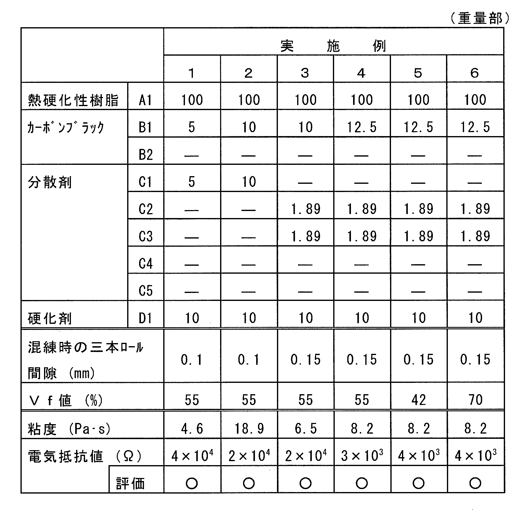
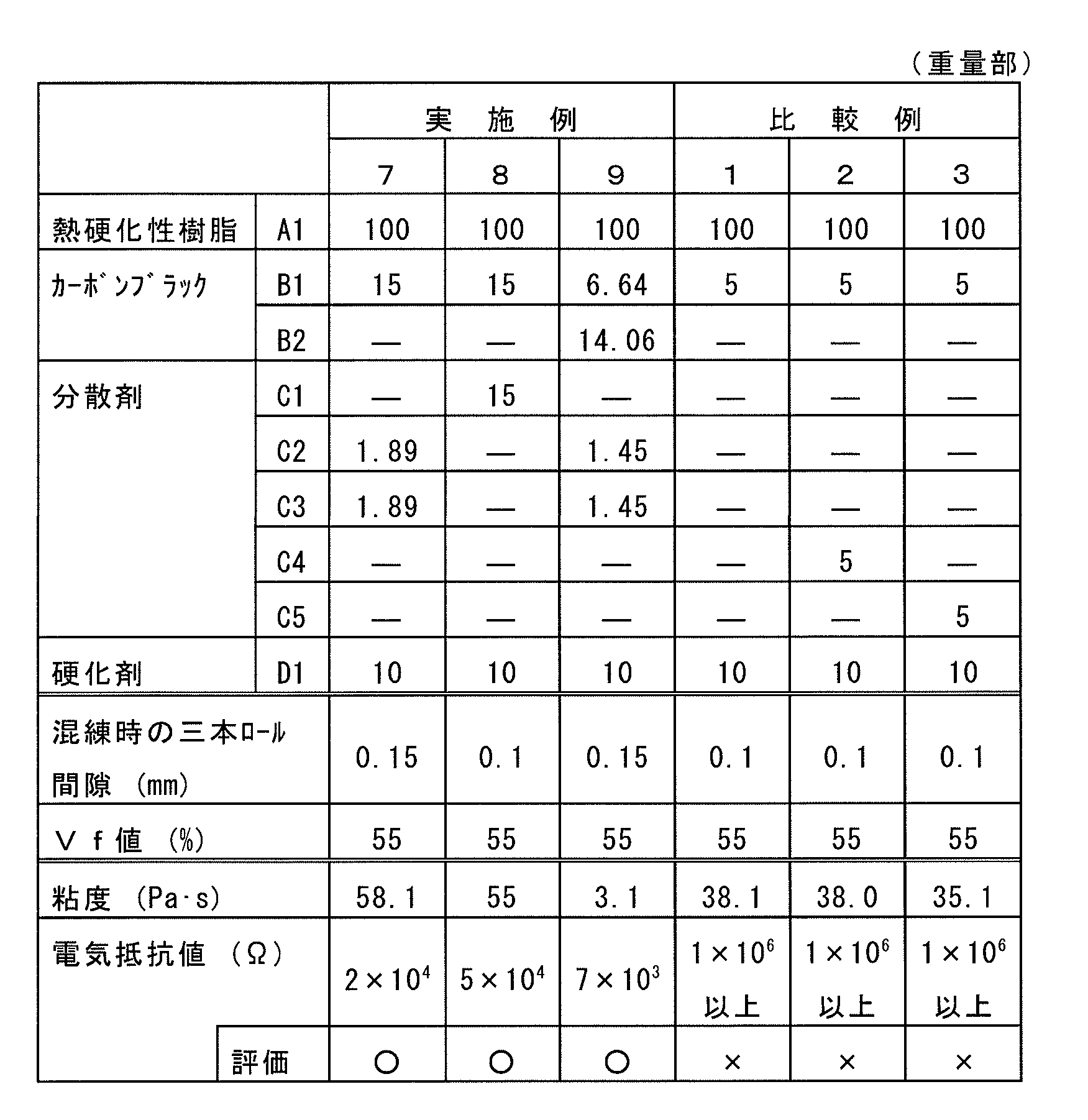
上記結果より、実施例1~9のシャフトは、比較例のシャフトに比べ、電気抵抗値が低く、導電性に優れていることがわかる。なお、比較例において、さらにカーボンブラックの配合量を高めたところ、樹脂組成物の粘度の急激な上昇(60Pa・s以上)がみられ、実施例や比較例の成形方法を適用してシャフトを製造することができなかった。
[実施例10]
実施例1と同様にして作製したシャフトの表面全面に、下記のコーティング処理1により、導電コーティング層の形成を行った。
〔コーティング処理1〕
まず、シャフトを、200g/LのNaOH水溶液を用いて、温度40℃で10分間エッチング処理した。ついで、上記シャフトを、Pd触媒付与剤(OPC-50インデューサー、奥野製薬工業社製)に40℃で5分間浸漬し、表面にPd触媒を付与した。続いて、上記シャフトを、活性化剤(OPC-150クリスター、奥野製薬工業社製)に25℃で5分間浸漬し、Pdイオンを金属化させた(活性化処理)。このようにして、シャフトの表面全面にめっき前処理を行った後、上記シャフトを無電解ニッケルめっき液(TMP化学ニッケルHRT、奥野製薬工業社製)に40℃で10分間浸漬し、厚み0.5μmの無電解ニッケルめっき層(導電コーティング層)を形成した。
実施例1と同様にして作製したシャフトの表面全面に、下記のコーティング処理1により、導電コーティング層の形成を行った。
〔コーティング処理1〕
まず、シャフトを、200g/LのNaOH水溶液を用いて、温度40℃で10分間エッチング処理した。ついで、上記シャフトを、Pd触媒付与剤(OPC-50インデューサー、奥野製薬工業社製)に40℃で5分間浸漬し、表面にPd触媒を付与した。続いて、上記シャフトを、活性化剤(OPC-150クリスター、奥野製薬工業社製)に25℃で5分間浸漬し、Pdイオンを金属化させた(活性化処理)。このようにして、シャフトの表面全面にめっき前処理を行った後、上記シャフトを無電解ニッケルめっき液(TMP化学ニッケルHRT、奥野製薬工業社製)に40℃で10分間浸漬し、厚み0.5μmの無電解ニッケルめっき層(導電コーティング層)を形成した。
[実施例11]
実施例4と同様にして作製したシャフトの表面全面に、上記コーティング処理1により、導電コーティング層の形成を行った。
実施例4と同様にして作製したシャフトの表面全面に、上記コーティング処理1により、導電コーティング層の形成を行った。
[実施例12]
実施例6と同様にして作製したシャフトの表面全面に、上記コーティング処理1により、導電コーティング層の形成を行った。
実施例6と同様にして作製したシャフトの表面全面に、上記コーティング処理1により、導電コーティング層の形成を行った。
[実施例13]
実施例6と同様にして作製したシャフトの表面全面に、下記のコーティング処理2により、導電コーティング層の形成を行った。
〔コーティング処理2〕
シャフトの表面全面に、イソプロパノール、ジメチルエーテル等の有機溶剤にグラファイト粉末が分散されたスプレー剤(グラファイトスプレー、ファインケミカルジャパン社製)をスプレーし、室温で1時間ほど乾燥させた後、さらに60℃で乾燥させ、導電コーティング層を形成した。
実施例6と同様にして作製したシャフトの表面全面に、下記のコーティング処理2により、導電コーティング層の形成を行った。
〔コーティング処理2〕
シャフトの表面全面に、イソプロパノール、ジメチルエーテル等の有機溶剤にグラファイト粉末が分散されたスプレー剤(グラファイトスプレー、ファインケミカルジャパン社製)をスプレーし、室温で1時間ほど乾燥させた後、さらに60℃で乾燥させ、導電コーティング層を形成した。
[実施例14]
実施例6と同様にして作製したシャフトの表面全面に、下記のコーティング処理3により、導電コーティング層の形成を行った。
〔コーティング処理3〕
シャフトの表面全面に、トルエン、ジメチルエーテル等の有機溶剤にSUS粉末が分散されたスプレー剤(ステンレススプレー、ファインケミカルジャパン社製)をスプレーし、室温で1時間ほど乾燥させた後、さらに60℃で乾燥させ、導電コーティング層を形成した。
実施例6と同様にして作製したシャフトの表面全面に、下記のコーティング処理3により、導電コーティング層の形成を行った。
〔コーティング処理3〕
シャフトの表面全面に、トルエン、ジメチルエーテル等の有機溶剤にSUS粉末が分散されたスプレー剤(ステンレススプレー、ファインケミカルジャパン社製)をスプレーし、室温で1時間ほど乾燥させた後、さらに60℃で乾燥させ、導電コーティング層を形成した。
[実施例15]
実施例6と同様にして作製したシャフトの表面全面に、下記のコーティング処理4により、導電コーティング層の形成を行った。
〔コーティング処理4〕
シャフトの表面全面に、トルエン、ジメチルエーテル等の有機溶剤にアルミニウム粉末が分散されたスプレー剤(ファイン・ヒートリフレクター、ファインケミカルジャパン社製)をスプレーし、室温で1時間ほど乾燥させた後、さらに60℃で乾燥させ、導電コーティング層を形成した。
実施例6と同様にして作製したシャフトの表面全面に、下記のコーティング処理4により、導電コーティング層の形成を行った。
〔コーティング処理4〕
シャフトの表面全面に、トルエン、ジメチルエーテル等の有機溶剤にアルミニウム粉末が分散されたスプレー剤(ファイン・ヒートリフレクター、ファインケミカルジャパン社製)をスプレーし、室温で1時間ほど乾燥させた後、さらに60℃で乾燥させ、導電コーティング層を形成した。
[実施例16]
実施例6と同様にして作製したシャフトの表面全面に、下記のコーティング処理5により、導電コーティング層の形成を行った。
〔コーティング処理5〕
シャフトの表面全面に、ブタン、プロパノール等の有機溶剤にグラファイト粉末とアルミニウム粉末が混合分散されたスプレー剤(ノンシーズ、ファインケミカルジャパン社製)をスプレーし、室温で1時間ほど乾燥させた後、さらに60℃で乾燥させ、導電コーティング層を形成した。
実施例6と同様にして作製したシャフトの表面全面に、下記のコーティング処理5により、導電コーティング層の形成を行った。
〔コーティング処理5〕
シャフトの表面全面に、ブタン、プロパノール等の有機溶剤にグラファイト粉末とアルミニウム粉末が混合分散されたスプレー剤(ノンシーズ、ファインケミカルジャパン社製)をスプレーし、室温で1時間ほど乾燥させた後、さらに60℃で乾燥させ、導電コーティング層を形成した。

上記結果より、実施例10~16のシャフトは、実施例1~9のシャフトよりも、さらに電気抵抗値が低く、より導電性に優れていることがわかる。
一方、下記の基準に従い、シャフトの曲げ弾性率の測定を行ったところ、実施例1の曲げ弾性率が43GPaであったのに対し、実施例10の曲げ弾性率が46GPaであり、実施例4の曲げ弾性率が43GPaであったのに対し、実施例11の曲げ弾性率が46GPaであり、さらに、実施例6の曲げ弾性率が52GPaだったのに対し、実施例12の曲げ弾性率が56GPaであった。このように、導電コーティング層の形成により、曲げ弾性率の向上効果が認められた。
〔曲げ弾性率〕
直径6mm、長さ125mmに統一したシャフトのサンプルに対して、JIS K7017 に準拠し、25℃温度下で、シャフトの三点曲げ試験(圧子半径:5mm、支持台の半径:2mm、支点間距離:100mm、試験速度:50mm/min)を行い、その曲げ弾性率(GPa)を測定した。
〔曲げ弾性率〕
直径6mm、長さ125mmに統一したシャフトのサンプルに対して、JIS K7017 に準拠し、25℃温度下で、シャフトの三点曲げ試験(圧子半径:5mm、支持台の半径:2mm、支点間距離:100mm、試験速度:50mm/min)を行い、その曲げ弾性率(GPa)を測定した。
なお、上記実施例においては、本発明における具体的な形態について示したが、上記実施例は単なる例示にすぎず、限定的に解釈されるものではない。当業者に明らかな様々な変形は、本発明の範囲内であることが企図されている。
本発明の導電性シャフトは、軽量で、強度が高く、導電性に優れ、しかも安価である。そのため、OA機器用導電性ロールの軸体として好ましく用いられるが、その他にも、導電性を要求されないOA機器用ロールの軸体や、防塵ロール、彫刻ロールなど産業用ロールの軸体、さらには、各種製品の構造部材等としても用いることができる。
1 シャフト
2 ガラス繊維束
2a ガラス繊維
3 カーボンブラック
4 マトリックス樹脂
2 ガラス繊維束
2a ガラス繊維
3 カーボンブラック
4 マトリックス樹脂
Claims (15)
- シャフトの長手方向に平行に連続ガラス繊維束が埋設された繊維強化樹脂製のシャフトであって、そのマトリックス樹脂が、下記の(A)を主成分とし下記の(B)~(D)成分を含有する樹脂組成物からなり、上記(B)成分が、粒子状でかつ連続ガラス繊維束を構成する連続ガラス繊維に沿って分布していることを特徴とする導電性シャフト。
(A)熱硬化性樹脂。
(B)カーボンブラック。
(C)塩基性官能基を有する分散剤。
(D)(A)成分の硬化剤。 - 上記分散剤(C)が、さらに熱硬化性樹脂(A)と親和性のある構造を有するものである請求項1記載の導電性シャフト。
- 上記熱硬化性樹脂(A)が、不飽和ポリエステル樹脂、ビニルエステル樹脂、エポキシ樹脂およびフェノール樹脂からなる群から選ばれた少なくとも一つである請求項1または2記載の導電性シャフト。
- 上記樹脂組成物におけるカーボンブラック(B)の割合が、熱硬化性樹脂(A)100重量部に対し5~15重量部の範囲である請求項1~3のいずれか一項に記載の導電性シャフト。
- 上記樹脂組成物における分散剤(C)の割合が、熱硬化性樹脂(A)100重量部に対し5~15重量部の範囲である請求項1~4のいずれか一項に記載の導電性シャフト。
- 上記樹脂組成物が、さらに、熱硬化性樹脂(A)と親和性のある構造を有するが塩基性官能基を有しない分散剤を含有する請求項1~5のいずれか一項に記載の導電性シャフト。
- 上記樹脂組成物における分散剤(C)の割合が、熱硬化性樹脂(A)100重量部に対し1.45~3.78重量部の範囲である請求項6記載の導電性シャフト。
- 上記導電性シャフトの表面に、さらに、金属めっき、金属粉またはグラファイトからなる導電コーティング層が形成されてなる、請求項1~7のいずれか一項に記載の導電性シャフト。
- 電気抵抗値が1×10⁶Ω未満である請求項1~8のいずれか一項に記載の導電性シャフト。
- OA機器用導電性ロールの軸体である、請求項1~9のいずれか一項に記載の導電性シャフト。
- 請求項10記載の導電性シャフトを軸体とするOA機器用導電性ロール。
- 帯電ロールまたは現像ロールに用いられる請求項11記載のOA機器用導電性ロール。
- 請求項1~10のいずれか一項に記載の導電性シャフトの製法であって、連続ガラス繊維を束ねた状態で、下記の(A)を主成分とし下記の(B)~(D)成分を含有する樹脂組成物の入った漕に引き込み、連続ガラス繊維を樹脂組成物に含浸させた後、金型に引き込み熱硬化させ、それにより得られた長尺の繊維強化樹脂成形品を、所定の長さに切断することを特徴とする導電性シャフトの製法。
(A)熱硬化性樹脂。
(B)カーボンブラック。
(C)塩基性官能基を有する分散剤。
(D)(A)成分の硬化剤。 - 上記含浸処理に用いる樹脂組成物が、三本ロールにより混練処理したものである請求項13記載の導電性シャフトの製法。
- 上記含浸処理に用いる樹脂組成物の粘度が0.5~60Pa・sの範囲である請求項13または14記載の導電性シャフトの製法。
Priority Applications (2)
| Application Number | Priority Date | Filing Date | Title |
|---|---|---|---|
| JP2015520760A JP5853124B2 (ja) | 2013-08-30 | 2014-08-29 | 導電性シャフトおよびそれを用いたoa機器用導電性ロール、並びに導電性シャフトの製法 |
| US14/719,691 US20150255188A1 (en) | 2013-08-30 | 2015-05-22 | Conductive shaft and conductive roll for oa equipment using the shaft, and method of producing conductive shaft |
Applications Claiming Priority (2)
| Application Number | Priority Date | Filing Date | Title |
|---|---|---|---|
| JP2013-179194 | 2013-08-30 | ||
| JP2013179194 | 2013-08-30 |
Related Child Applications (1)
| Application Number | Title | Priority Date | Filing Date |
|---|---|---|---|
| US14/719,691 Continuation US20150255188A1 (en) | 2013-08-30 | 2015-05-22 | Conductive shaft and conductive roll for oa equipment using the shaft, and method of producing conductive shaft |
Publications (1)
| Publication Number | Publication Date |
|---|---|
| WO2015030154A1 true WO2015030154A1 (ja) | 2015-03-05 |
Family
ID=52586701
Family Applications (1)
| Application Number | Title | Priority Date | Filing Date |
|---|---|---|---|
| PCT/JP2014/072680 Ceased WO2015030154A1 (ja) | 2013-08-30 | 2014-08-29 | 導電性シャフトおよびそれを用いたoa機器用導電性ロール、並びに導電性シャフトの製法 |
Country Status (3)
| Country | Link |
|---|---|
| US (1) | US20150255188A1 (ja) |
| JP (1) | JP5853124B2 (ja) |
| WO (1) | WO2015030154A1 (ja) |
Cited By (1)
| Publication number | Priority date | Publication date | Assignee | Title |
|---|---|---|---|---|
| JP2017116049A (ja) * | 2015-12-25 | 2017-06-29 | 住友理工株式会社 | シャフトおよびそれを用いたoa機器用ロール、並びにシャフトの製法 |
Families Citing this family (1)
| Publication number | Priority date | Publication date | Assignee | Title |
|---|---|---|---|---|
| CN113999515B (zh) * | 2021-12-10 | 2023-04-07 | 南京经略复合材料有限公司 | 一种玻纤增强聚氨酯材料、支护梁及支护梁的制备工艺 |
Citations (5)
| Publication number | Priority date | Publication date | Assignee | Title |
|---|---|---|---|---|
| JP2006220742A (ja) * | 2005-02-08 | 2006-08-24 | Nitto Kogyo Co Ltd | 作像ローラ |
| JP2007255507A (ja) * | 2006-03-22 | 2007-10-04 | Kyocera Chemical Corp | 搬送用シャフト |
| JP2008020634A (ja) * | 2006-07-12 | 2008-01-31 | Synztec Co Ltd | 作像ローラ |
| JP2009138032A (ja) * | 2007-12-03 | 2009-06-25 | Mitsubishi Rayon Co Ltd | カーボンナノチューブ含有マトリクス樹脂の製造方法 |
| US20120201572A1 (en) * | 2011-02-09 | 2012-08-09 | Samsung Electronics Co., Ltd. | Roller for imaging apparatus and imaging apparatus including the roller |
-
2014
- 2014-08-29 JP JP2015520760A patent/JP5853124B2/ja not_active Expired - Fee Related
- 2014-08-29 WO PCT/JP2014/072680 patent/WO2015030154A1/ja not_active Ceased
-
2015
- 2015-05-22 US US14/719,691 patent/US20150255188A1/en not_active Abandoned
Patent Citations (5)
| Publication number | Priority date | Publication date | Assignee | Title |
|---|---|---|---|---|
| JP2006220742A (ja) * | 2005-02-08 | 2006-08-24 | Nitto Kogyo Co Ltd | 作像ローラ |
| JP2007255507A (ja) * | 2006-03-22 | 2007-10-04 | Kyocera Chemical Corp | 搬送用シャフト |
| JP2008020634A (ja) * | 2006-07-12 | 2008-01-31 | Synztec Co Ltd | 作像ローラ |
| JP2009138032A (ja) * | 2007-12-03 | 2009-06-25 | Mitsubishi Rayon Co Ltd | カーボンナノチューブ含有マトリクス樹脂の製造方法 |
| US20120201572A1 (en) * | 2011-02-09 | 2012-08-09 | Samsung Electronics Co., Ltd. | Roller for imaging apparatus and imaging apparatus including the roller |
Cited By (1)
| Publication number | Priority date | Publication date | Assignee | Title |
|---|---|---|---|---|
| JP2017116049A (ja) * | 2015-12-25 | 2017-06-29 | 住友理工株式会社 | シャフトおよびそれを用いたoa機器用ロール、並びにシャフトの製法 |
Also Published As
| Publication number | Publication date |
|---|---|
| JPWO2015030154A1 (ja) | 2017-03-02 |
| JP5853124B2 (ja) | 2016-02-09 |
| US20150255188A1 (en) | 2015-09-10 |
Similar Documents
| Publication | Publication Date | Title |
|---|---|---|
| JP5831668B1 (ja) | プリプレグおよび繊維強化複合材料 | |
| CN104508022B (zh) | 预浸料坯及碳纤维增强复合材料 | |
| US9982086B2 (en) | Epoxy resin composition, prepreg, fiber reinforced plastic material, and manufacturing method for fiber reinforced plastic material | |
| CN102333647B (zh) | 可用于非纤维素类纤维上胶剂、涂层剂或粘结组合物的组合物以及含有该组合物的复合材料 | |
| US20150275061A1 (en) | Heat dissipation paint composition and heat dissipation structure | |
| TWI778041B (zh) | 纖維強化複合材料用環氧樹脂組成物、纖維強化複合材料及成形體 | |
| KR20150018540A (ko) | 에폭시 수지 조성물 | |
| JP5929046B2 (ja) | 炭素繊維織物プリプレグおよび炭素繊維強化複合材料 | |
| JP2011213991A (ja) | 炭素繊維強化複合材料 | |
| JP6056517B2 (ja) | サイジング剤塗布炭素繊維、サイジング剤塗布炭素繊維の製造方法、およびプリプレグならびに炭素繊維強化熱可塑性樹脂組成物 | |
| US20180233250A1 (en) | Conductive film and method for producing the same | |
| JP2013173812A (ja) | プリプレグおよび炭素繊維強化複合材料 | |
| JP2017132932A (ja) | プリプレグおよび繊維強化複合材料 | |
| US9005093B2 (en) | Roller for imaging apparatus and imaging apparatus including the roller | |
| TW202305044A (zh) | 碳纖維束、預浸體、纖維強化複合材料 | |
| JP6394085B2 (ja) | サイジング剤塗布炭素繊維およびその製造方法、プリプレグおよび炭素繊維強化複合材料 | |
| JP5853124B2 (ja) | 導電性シャフトおよびそれを用いたoa機器用導電性ロール、並びに導電性シャフトの製法 | |
| JP2015120837A (ja) | 微細炭素繊維含有水系ポリウレタン樹脂溶液及びそれを用いた導電膜 | |
| WO2019189750A1 (ja) | 導電性組成物及びそれを用いた導電性構造体 | |
| JP2012144708A (ja) | プリプレグおよび炭素繊維強化複合材料 | |
| Li et al. | Improved strength, toughness and electrical properties of rigid polyurethane composites reinforced with Ni-coated carbon fibers | |
| JP2015190575A (ja) | 導電性シャフトおよびそれを用いたoa機器用導電性ロール、並びに導電性シャフトの製法 | |
| JP6774807B2 (ja) | 繊維強化樹脂成形体およびその製造方法 | |
| JP2017116049A (ja) | シャフトおよびそれを用いたoa機器用ロール、並びにシャフトの製法 | |
| KR20240177632A (ko) | 전기영동증착법을 이용한 탄소섬유 강화 복합재 제조방법 |
Legal Events
| Date | Code | Title | Description |
|---|---|---|---|
| ENP | Entry into the national phase |
Ref document number: 2015520760 Country of ref document: JP Kind code of ref document: A |
|
| 121 | Ep: the epo has been informed by wipo that ep was designated in this application |
Ref document number: 14840031 Country of ref document: EP Kind code of ref document: A1 |
|
| NENP | Non-entry into the national phase |
Ref country code: DE |
|
| 122 | Ep: pct application non-entry in european phase |
Ref document number: 14840031 Country of ref document: EP Kind code of ref document: A1 |