WO2015030045A1 - 多孔質金属ワイヤー、それを含有する膜、及びそれらの製造方法 - Google Patents
多孔質金属ワイヤー、それを含有する膜、及びそれらの製造方法 Download PDFInfo
- Publication number
- WO2015030045A1 WO2015030045A1 PCT/JP2014/072409 JP2014072409W WO2015030045A1 WO 2015030045 A1 WO2015030045 A1 WO 2015030045A1 JP 2014072409 W JP2014072409 W JP 2014072409W WO 2015030045 A1 WO2015030045 A1 WO 2015030045A1
- Authority
- WO
- WIPO (PCT)
- Prior art keywords
- fibrous
- metal wire
- metal
- reduction
- salt
- Prior art date
- Legal status (The legal status is an assumption and is not a legal conclusion. Google has not performed a legal analysis and makes no representation as to the accuracy of the status listed.)
- Ceased
Links
Images


















Classifications
-
- B—PERFORMING OPERATIONS; TRANSPORTING
- B22—CASTING; POWDER METALLURGY
- B22F—WORKING METALLIC POWDER; MANUFACTURE OF ARTICLES FROM METALLIC POWDER; MAKING METALLIC POWDER; APPARATUS OR DEVICES SPECIALLY ADAPTED FOR METALLIC POWDER
- B22F9/00—Making metallic powder or suspensions thereof
- B22F9/16—Making metallic powder or suspensions thereof using chemical processes
- B22F9/18—Making metallic powder or suspensions thereof using chemical processes with reduction of metal compounds
- B22F9/20—Making metallic powder or suspensions thereof using chemical processes with reduction of metal compounds starting from solid metal compounds
- B22F9/22—Making metallic powder or suspensions thereof using chemical processes with reduction of metal compounds starting from solid metal compounds using gaseous reductors
-
- B—PERFORMING OPERATIONS; TRANSPORTING
- B22—CASTING; POWDER METALLURGY
- B22F—WORKING METALLIC POWDER; MANUFACTURE OF ARTICLES FROM METALLIC POWDER; MAKING METALLIC POWDER; APPARATUS OR DEVICES SPECIALLY ADAPTED FOR METALLIC POWDER
- B22F1/00—Metallic powder; Treatment of metallic powder, e.g. to facilitate working or to improve properties
- B22F1/05—Metallic powder characterised by the size or surface area of the particles
- B22F1/052—Metallic powder characterised by the size or surface area of the particles characterised by a mixture of particles of different sizes or by the particle size distribution
-
- B—PERFORMING OPERATIONS; TRANSPORTING
- B22—CASTING; POWDER METALLURGY
- B22F—WORKING METALLIC POWDER; MANUFACTURE OF ARTICLES FROM METALLIC POWDER; MAKING METALLIC POWDER; APPARATUS OR DEVICES SPECIALLY ADAPTED FOR METALLIC POWDER
- B22F1/00—Metallic powder; Treatment of metallic powder, e.g. to facilitate working or to improve properties
- B22F1/05—Metallic powder characterised by the size or surface area of the particles
- B22F1/054—Nanosized particles
-
- B—PERFORMING OPERATIONS; TRANSPORTING
- B22—CASTING; POWDER METALLURGY
- B22F—WORKING METALLIC POWDER; MANUFACTURE OF ARTICLES FROM METALLIC POWDER; MAKING METALLIC POWDER; APPARATUS OR DEVICES SPECIALLY ADAPTED FOR METALLIC POWDER
- B22F1/00—Metallic powder; Treatment of metallic powder, e.g. to facilitate working or to improve properties
- B22F1/06—Metallic powder characterised by the shape of the particles
- B22F1/062—Fibrous particles
-
- B—PERFORMING OPERATIONS; TRANSPORTING
- B22—CASTING; POWDER METALLURGY
- B22F—WORKING METALLIC POWDER; MANUFACTURE OF ARTICLES FROM METALLIC POWDER; MAKING METALLIC POWDER; APPARATUS OR DEVICES SPECIALLY ADAPTED FOR METALLIC POWDER
- B22F9/00—Making metallic powder or suspensions thereof
- B22F9/02—Making metallic powder or suspensions thereof using physical processes
-
- C—CHEMISTRY; METALLURGY
- C07—ORGANIC CHEMISTRY
- C07C—ACYCLIC OR CARBOCYCLIC COMPOUNDS
- C07C51/00—Preparation of carboxylic acids or their salts, halides or anhydrides
- C07C51/41—Preparation of salts of carboxylic acids
Definitions
- the present invention relates to a porous metal wire, a film containing the same, and a method for producing the same, and more specifically, a porous metal nanowire or a porous metal microwire that can be suitably used for a transparent conductive film, a fibrous shape, and the like.
- the present invention relates to a method for producing a porous metal wire using an organic metal salt, a membrane containing a porous metal wire, a composite, a method for producing the same, and a method for producing a fibrous organic metal salt.
- Silver nanowires have attracted attention as a material for forming a transparent conductive film in place of indium tin oxide (ITO) (for example, JP 2009-299162 A (Patent Document 1)).
- ITO indium tin oxide
- Patent Document 1 a method of coating the (100) surface of silver with a protective agent and specifically growing (anisotropic growth) only the (111) surface (Y. Sun et al. (Non-Patent Document 1)) and a method of reducing silver ions in a template such as a carbon nanotube are known.
- This invention is made
- the aim is to provide a possible method.
- porous metal nanowires and metal microwires can be obtained by reduction with any one selected from the group consisting of solid-gas reduction in contact with a reducing agent, and the present invention has been completed.
- the method for producing a porous metal wire of the present invention includes a step of forming a porous metal wire in which metal nanoparticles are connected by reducing a fibrous organometallic salt,
- the reduction is any one selected from the group consisting of plasma reduction, photoreduction, laser irradiation reduction, and solid-gas reduction in which the fibrous organometallic salt is brought into contact with a gaseous reducing agent. is there.
- the reducing agent is preferably at least one selected from the group consisting of hydrazine, sodium borohydride, diborane and hydrogen. .
- the plasma reduction irradiates at least one gas selected from the group consisting of Ar, He, and N 2 with microwaves. Reduction with plasma generated in this manner is preferable.
- the fibrous organic metal salt is preferably a carboxylic acid metal salt, and at least one selected from the group consisting of an acetic acid metal salt, a propionic acid metal salt, a butyric acid metal salt, a valeric acid metal salt, and a hexanoic acid metal salt. Species are more preferred.
- a step of irradiating a solution containing a metal compound and an organic acid with ultrasonic waves in the atmosphere A solution containing a compound and an organic acid is irradiated with an ultrasonic wave in the atmosphere to form a nucleus composed of an organic metal salt, and a dispersion containing the nucleus composed of the organometallic salt is irradiated with microwaves to irradiate the nucleus.
- a step of growing anisotropic grains may be further included.
- the metal compound is preferably a metal oxide.
- the porous metal wire of the present invention is formed by connecting metal nanoparticles.
- the average short axis length of the porous metal wire is measured with a scanning electron microscope as a short side, and the length of the porous metal wire is twice as long as the average short axis length. It is preferable that the average of the void ratio obtained by measuring the ratio of the projected area of the void in the microanalysis range is 1 to 50%.
- the average particle diameter of the metal nanoparticles is preferably 10 to 100 nm, and the average aspect ratio (major axis length / minor axis length) is preferably 8 to 25. .
- the film of the present invention contains the porous metal wire of the present invention.
- the porous metal wires are preferably bonded to each other.
- the composite of the present invention comprises a substrate containing polycarbonate and the porous metal wire of the present invention.
- the film production method of the present invention includes a step of applying a coating liquid containing a fibrous organometallic salt and a solvent on a substrate, a step of removing the solvent, and reducing the organometallic salt. Forming a film containing a porous metal wire to which metal nanoparticles are connected, and The reduction is any one selected from the group consisting of plasma reduction, photoreduction, laser irradiation reduction, and solid-gas reduction in which the fibrous organometallic salt is brought into contact with a gaseous reducing agent. is there.
- the manufacturing method of the composite of the present invention includes a step of applying a coating liquid containing a fibrous organometallic salt and a solvent on a substrate containing polycarbonate, a step of removing the solvent, and the fibrous Reducing the organometallic salt to form a porous metal wire in which metal nanoparticles are connected, and obtaining a composite comprising the substrate and the porous metal wire, and the reduction includes the step of This is solid-gas reduction in which a fibrous organic metal salt is brought into contact with hydrazine.
- the first method for producing a fibrous organic metal salt of the present invention is to form a fibrous organic metal salt by irradiating a solution containing a metal compound and an organic acid with ultrasonic waves in the air.
- a solution containing a metal compound and an organic acid is irradiated with an ultrasonic wave in the atmosphere to form a nucleus composed of the organic metal salt, and the organic A fibrous organic metal salt is formed by irradiating a dispersion liquid containing a nucleus composed of a metal salt with microwaves to grow the nucleus anisotropically.
- porous metal nanowires and metal microwires can be produced relatively easily without using additives such as a protective agent and a template.
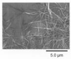
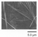
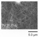
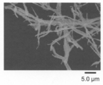
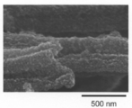
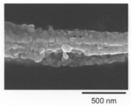
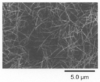
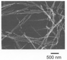
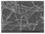
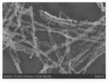
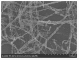
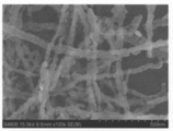
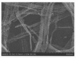
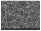
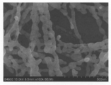
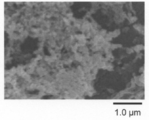
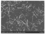
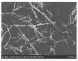
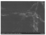
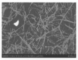
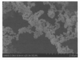
- 4 is a SEM photograph of the powder obtained in Example 3.
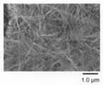
- 4 is a SEM photograph of the powder obtained in Example 4.
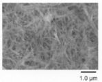
- 4 is a SEM photograph of the powder obtained in Example 5.
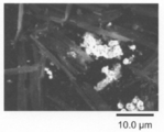
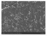
- 6 is a SEM photograph of the powder obtained in Example 6.
- 6 is a SEM photograph of the powder obtained in Example 6.
- 4 is a SEM photograph of the powder obtained in Example 7.
- 2 is a SEM photograph of the powder obtained in Example 8.
- 2 is a SEM photograph of the powder obtained in Example 8.
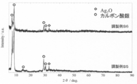
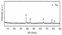
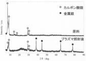
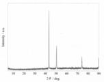
- 10 is a graph showing an X-ray diffraction pattern of the powder obtained in Example 15.
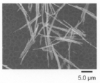
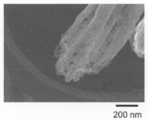
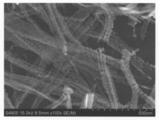
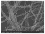
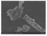
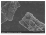
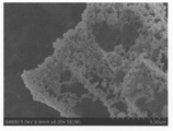
- 2 is a SEM photograph of the powder obtained in Example 15.
- 2 is a SEM photograph of the powder obtained in Example 15.
- 2 is a SEM photograph of powder obtained in Example 16.
- 2 is a SEM photograph of powder obtained in Example 16.
- 2 is a SEM photograph of powder obtained in Example 17.
- 2 is a SEM photograph of powder obtained in Example 17.
- 2 is a SEM photograph of powder obtained in Example 18.
- 2 is a SEM photograph of powder obtained in Example 18.
- 2 is a SEM photograph of the powder obtained in Example 19.
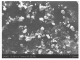
- 2 is a SEM photograph of the powder obtained in Comparative Example 1.
- 4 is a SEM photograph of the powder obtained in Comparative Example 2.
- 4 is a SEM photograph of the powder obtained in Comparative Example 3.
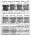
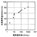
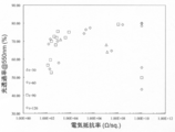
- 2 is a photograph of the film obtained in Example 20. It is a graph which shows the relationship between the electrical resistivity of the film
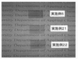
- Example 2 is a photograph of the films obtained in Example 6 and Examples 21-22.
- 2 is a SEM photograph of the composite surface obtained in Example 23.
- 2 is a SEM photograph of the composite surface obtained in Example 23.
- 2 is a SEM photograph of the composite surface obtained in Example 23. It is a graph which shows the relationship between the electrical resistivity and light transmittance of the composite_body
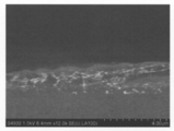
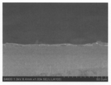
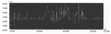
- 2 is a SEM photograph of a cross section of a composite obtained in Example 24 with a reduction time of 120 seconds. It is a SEM photograph of the section of the polycarbonate substrate before film formation used in Example 24. It is the BSE image of the surface of the part by which the blackening of the composite_body
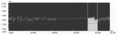
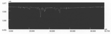
- FIG. 2 is a laser micrograph of the composite surface obtained in Example 24 with a reduction time of 120 seconds. It is sectional drawing obtained by laser microscope observation of the composite_body
- the method for producing a porous metal wire of the present invention includes a step (reduction step) of forming a porous metal wire to which metal nanoparticles are connected by reducing a fibrous organometallic salt,
- the reduction is any one selected from the group consisting of plasma reduction, photoreduction, laser irradiation reduction, and solid-gas reduction in which the fibrous organometallic salt is brought into contact with a gaseous reducing agent. is there.
- the reduction step according to the present invention is any one selected from the group consisting of plasma reduction, photoreduction, laser irradiation reduction, and solid-gas reduction in which the fibrous organometallic salt is brought into contact with a gaseous reducing agent.
- a desired metal wire can be obtained without impairing the fiber shape of the organic metal salt.
- the organic acid residue forming the organic metal salt is removed by this reduction treatment, pores are formed in the portion where the organic acid residue was present in the fibrous organic metal salt, The resulting metal wire has a porous structure. Further, this porous metal wire has a structure in which metal nanoparticles are connected.
- the obtained metal wire forms the porous structure which the metal nanoparticle connected in this way, it has an uneven
- the fibrous organic metal salt used in the present invention is not particularly limited as long as it is an organic metal salt containing a metal atom constituting a desired metal wire and is fibrous.
- the “fibrous” includes shapes such as needles, plates, and cylinders.
- Examples of the metal atom constituting such an organic metal salt include a silver atom, a gold atom, a platinum atom, a copper atom, a nickel atom, an aluminum atom, and a tin atom, and among them, a silver atom, a platinum atom, and a copper atom. Is preferred. Such metal atoms may be used alone or in combination of two or more. Further, the kind of the organic metal salt is not particularly limited as long as it is reduced to a single metal, but for example, a carboxylic acid metal salt is preferable, and an acetic acid metal salt, a propionic acid metal salt, a butyric acid metal salt, valeric acid.
- Metal salts and hexanoic acid metal salts are more preferred. These organic metal salts may be used alone or in combination of two or more. Further, an intermediate of two or more kinds of organometallic salts (preferably a multimer such as a dimer) becomes a fibrous organometallic salt having a relatively large aspect ratio. By using the body, a porous metal wire having a large aspect ratio can be obtained. As such a fibrous organic metal salt, a commercially available one can be used, but one produced by the method described later may be used.
- the average minor axis length of the fibrous organometallic salt is preferably 15 ⁇ m or less, preferably 5 ⁇ m or less, and particularly preferably 2 ⁇ m or less from the viewpoint of obtaining a metal wire having a sufficiently large aspect ratio.
- the lower limit of the average minor axis length of the fibrous organic metal salt is not particularly limited, but is usually 0.1 ⁇ m or more.
- the average major axis length of the fibrous organometallic salt is preferably 1 ⁇ m or more, more preferably 5 ⁇ m or more, further preferably 10 ⁇ m or more, particularly preferably 15 ⁇ m or more, and most preferably 20 ⁇ m or more. If the average major axis length of the fibrous organic metal salt is less than the lower limit, the aspect ratio of the fibrous organic metal salt tends to be small, and a desired metal wire tends not to be obtained.
- the upper limit of the average major axis length of the fibrous organic metal salt is not particularly limited, but is usually 50 ⁇ m or less.
- the average value of the aspect ratio of the fibrous organic metal salt is preferably 3.3 or more, preferably 6.5 or more, more preferably 9 or more from the viewpoint of obtaining a metal wire having a sufficiently large aspect ratio.
- 12 or more is more preferable, and 14 or more is particularly preferable.
- the average aspect ratio of the fibrous organic metal salt is less than the lower limit, a metal wire having a desired aspect ratio tends not to be obtained.
- it is 25 or less.
- the major axis length, minor axis length, and aspect ratio (major axis length / minor axis length) of the fibrous organometallic salt are measured by observation with a scanning electron microscope (SEM).
- the major axis length is the length of the major axis when the longitudinal direction is the major axis when the fibrous organometallic salt is projected onto a plane.
- the short axis length means a minimum value of the length of the short axis when a direction perpendicular to the long axis when the fibrous organometallic salt is projected onto a plane is a short axis.
- the maximum value / minimum value of the length of the short axis is 3 or more, it means the average of the minimum value and the maximum value.
- the long axis refers to the longest part, and when the fibrous organic metal salt is plate-shaped (that is, prismatic) or cylindrical, the long axis is the prism or Refers to the height of a cylinder, and when the fibrous organometallic salt is plate-like, the short axis is the width when the longitudinal direction of the cross section perpendicular to the long axis is the width and the short direction is the thickness. It means the width.
- the average major axis length, the average minor axis length, and the average aspect ratio are an arbitrary 100 fibrous organometallic salts extracted, and the major axis length, minor axis length, and The average aspect ratio.
- the organic metal salt is solid-gas reduced by bringing a fibrous organic metal salt into contact with a gaseous reducing agent.
- the reducing agent used in the solid-gas reduction is not particularly limited as long as the organic metal salt can be solid-gas reduced to a single metal, but for example, hydrazine, sodium borohydride, diborane, and hydrogen are preferable. Such reducing agents may be used alone or in combination of two or more.
- the method for contacting the fibrous organic metal salt with the gaseous reducing agent is not particularly limited.
- the liquid reducing agent is subjected to a heat treatment or the like.
- Examples include a method in which steam is generated and the reducing agent vapor is brought into contact with a fibrous organic metal salt, and a gaseous reducing agent such as hydrogen is brought into direct contact with the fibrous organic metal salt.
- the temperature is preferably 40 to 100 ° C., more preferably 60 to 100 ° C. in the case of hydrazine reduction. In the case of hydrogen reduction, 40 to 500 ° C. is preferable.
- the reduction temperature is less than the lower limit, the organometallic salt is not sufficiently reduced, and the organometallic salt tends to remain in the metal wire.
- the upper limit is exceeded, the metal nanoparticles constituting the metal wire are reduced. Since it becomes difficult to maintain the fiber shape of the organic metal salt before the reduction treatment because of grain growth, there is a tendency that a desired metal wire cannot be obtained.
- the solid-gas reduction treatment time is preferably 30 to 300 seconds, more preferably 40 to 300 seconds, and further preferably 60 to 200 seconds.
- the reduction time is less than the lower limit, the organometallic salt is not sufficiently reduced, and the organometallic salt tends to remain in the metal wire.
- the upper limit is exceeded, the metal nanoparticles constituting the metal wire are reduced. Grain growth tends to result in failure to obtain the desired metal wire.
- the time (reduction time) is particularly preferably 40 to 100 seconds, and particularly preferably 60 to 90 seconds.
- the plasma reduction at least one gas selected from the group consisting of Ar, He, and N 2 is irradiated with microwaves to generate plasma, and this is irradiated onto a fibrous organometallic salt to form the organic A method of reducing a metal salt is mentioned.
- the microwave output in the plasma reduction treatment according to the present invention is preferably 50 to 200 W, and more preferably 70 to 200 W.
- the organometallic salt is not sufficiently reduced, and the organometallic salt tends to remain in the metal wire. Since the particles grow or it is difficult to maintain the fiber shape of the organometallic salt before the reduction treatment, the porosity is lowered and a desired metal wire tends not to be obtained.
- the gas flow rate in the plasma reduction treatment according to the present invention is preferably 1 to 30 L / min, more preferably 10 to 30 L / min.
- the gas flow rate is less than the lower limit, it tends to be difficult to stably generate plasma, and when it exceeds the upper limit, it tends to be difficult to generate plasma sufficiently.
- the plasma reduction treatment time (plasma irradiation time) is preferably 10 to 600 seconds, more preferably 120 to 300 seconds.
- the reduction time is less than the lower limit, the organometallic salt is not sufficiently reduced, and the organometallic salt tends to remain in the metal wire.
- the upper limit is exceeded, the metal nanoparticles constituting the metal wire are reduced. Grain growth tends to result in failure to obtain the desired metal wire.
- the photoreduction examples include a method of reducing the organometallic salt by irradiating a fibrous organic metal salt with a flashlight.
- the flashlight irradiation output is preferably 0.5 to 10 J / cm 2 , more preferably 1.5 to 5 J / cm 2 .
- the irradiation power of the flashlight is less than the lower limit, the organic metal salt is not sufficiently reduced, and the organic metal salt tends to remain in the metal wire.
- the upper limit is exceeded, the metal constituting the metal wire Since the nanoparticles grow or the fiber shape of the organometallic salt before the reduction treatment is difficult to maintain, the porosity is lowered and a desired metal wire tends not to be obtained.
- the photoreduction treatment time is preferably 1 to 50 ms, more preferably 2 to 20 ms.
- the reduction time is less than the lower limit, the organometallic salt is not sufficiently reduced, and the organometallic salt tends to remain in the metal wire.
- the upper limit is exceeded, the metal nanoparticles constituting the metal wire are reduced. Grain growth tends to result in failure to obtain the desired metal wire.
- the laser irradiation reduction examples include a method in which a fibrous organic metal salt is irradiated with laser light to reduce the organic metal salt.
- the laser beam irradiation output is preferably 0.1 to 100 W, and more preferably 1 to 50 W.
- the irradiation power of the laser beam is less than the lower limit, the organic metal salt is not sufficiently reduced, and the organic metal salt tends to remain in the metal wire.
- the upper limit is exceeded, the metal constituting the metal wire Since the nanoparticles grow or the fiber shape of the organometallic salt before the reduction treatment is difficult to maintain, the porosity is lowered and a desired metal wire tends not to be obtained.
- the time for the laser irradiation reduction treatment is preferably from 0.1 to 100 mm / s, and more preferably from 1 to 50 mm / s.
- the reduction time is less than the lower limit, the organometallic salt is not sufficiently reduced, and the organometallic salt tends to remain in the metal wire.
- the upper limit is exceeded, the metal nanoparticles constituting the metal wire are reduced. Grain growth tends to result in failure to obtain the desired metal wire.
- the fibrous organic metal salt is reduced while maintaining the shape without impairing the shape of the fiber, and the porous metal wire of the present invention can be obtained.
- maintaining the fibrous shape means that the change amount of the short axis length of the obtained porous metal wire is small with respect to the short axis length of the fibrous organic metal salt before reduction, It can be measured by observation with a scanning electron microscope (SEM), specifically, for any average short axis length of any 100 fibrous organometallic salts before reduction, The average minor axis length of 100 porous metal wires is in the range of 50 to 100%.
- SEM scanning electron microscope
- the fibrous organic metal salt used in the present invention a commercially available one may be used as long as it satisfies the above conditions.
- the solution containing the metal compound and the organic acid is irradiated with ultrasonic waves in the air.
- a fibrous organic metal salt having a large aspect ratio preferably an average value of aspect ratio of 6.5 or more and an average minor axis length of 2 ⁇ m or less) It can be easily obtained while suppressing.
- the metal compound is a metal compound containing a metal atom constituting a desired organic metal salt, and is not particularly limited as long as it is other than the target organic metal salt, metal oxide, inorganic metal salt, Examples include organic metal salts other than the target organic metal salt. Such metal compounds may be used alone or in combination of two or more.
- Inorganic metal salts include nitrates, sulfates, oxalates, chlorides, hydroxides, sulfites, thiosulfates, persulfates, pernitrates, and hyponitrites.
- organic metal salt examples include metal salt of carboxylic acid and metal salt of sulfonic acid such as metal salt of acetic acid, metal salt of propionic acid, metal salt of butyric acid, metal salt of valeric acid, metal salt of hexanoic acid.
- the “organic metal salt other than the target organic metal salt” means, for example, when the target organic metal salt is an “acetic acid metal salt”, a propionic acid metal salt, a butyric acid metal salt, or a valeric acid metal salt.
- Carboxylic acid metal salt other than metal acetate such as hexanoic acid metal salt
- organic metal salt other than carboxylate metal salt such as sulfonic acid metal salt.
- metal oxides are preferred from the viewpoint that the desired fibrous organometallic salt can be easily obtained.
- the organic acid is preferably a carboxylic acid, more preferably acetic acid, propionic acid, butyric acid, valeric acid, or hexanoic acid, and particularly preferably acetic acid.
- Such organic acids may be used alone or in combination of two or more.
- the “particle” includes not only the “granular” shape but also the “fibrous” shape.
- the “fibrous” means that the aspect ratio is 3 or more.
- the granular means that the aspect ratio is less than 3.
- the major axis length, minor axis length, and aspect ratio of the particle can be measured by observation with a scanning electron microscope (SEM), and the major axis length refers to a case where the particle is projected onto a plane.
- the major axis is the length of the major axis
- the minor axis length is the minimum length of the minor axis when the direction perpendicular to the major axis is the minor axis.
- the maximum value / minimum value of the length of the short axis is 3 or more, it means the average of the minimum value and the maximum value.
- the major axis refers to the longest part, and when the particles are plate-shaped (that is, prismatic) or cylindrical, the major axis is the height of the prism or cylinder.
- the short axis means the width when the longitudinal direction of the cross section perpendicular to the long axis is the width and the short direction is the thickness. .
- a fibrous organic metal salt comprising an intermediate (preferably a multimer such as a dimer) of two or more organic metal salts having a relatively large aspect ratio. Therefore, the aspect ratio of the porous metal wire obtained by solid-air reduction of the fibrous organic metal salt tends to increase.
- the reason why the unreacted metal compound hardly remains by adding an organic acid is presumed as follows. That is, by adding an organic acid, metal ions are easily generated from the metal compound, and the metal ion concentration in the mixed solution is increased. In such a mixed solution having a high metal ion concentration, the reaction between the metal ions and the organic acid residue is likely to proceed, so that it is assumed that the unreacted metal compound hardly remains.
- the solvent used in the solution containing the metal compound and the organic acid is not particularly limited, and may be an aqueous solvent or an organic solvent.
- Water is mentioned as an aqueous solvent
- Alcohol for example, ethanol etc.
- Such a solvent may be used individually by 1 type, or may use 2 or more types together.
- the solvent is preferably subjected to deaeration treatment in advance.
- the metal compound, organic acid and solvent are mixed.
- the concentration of the metal compound in the resulting mixed solution is not particularly limited, but is preferably 0.001 to 0.1 g / ml.
- concentration of the metal compound is less than the lower limit, the amount of the organic metal salt is reduced, and the yield of the metal wire tends to decrease.
- the upper limit is exceeded, coarse organometallic salt particles are generated. Or an aggregate of organometallic salt is easily generated, and the desired fibrous organometallic salt and metal wire tend not to be obtained.
- the addition amount of the organic acid is preferably 0.3 parts by mass or more and more preferably 0.4 parts by mass or more with respect to 1 part by mass of the metal compound.
- the addition amount of the organic acid is less than the lower limit, the effect of adding the organic acid is not sufficiently obtained, the unreacted metal compound tends to remain, and the aspect ratio of the obtained organometallic salt particles is It tends to be too small and a desired fibrous organometallic salt cannot be obtained only by ultrasonic irradiation.
- the mixed solution containing the metal compound and the organic acid is irradiated with ultrasonic waves in the air.
- the metal compound and the organic acid react to produce organometallic salt particles.
- by irradiating with ultrasonic waves it is possible to control the nucleation at the initial stage of the reaction or promote the reaction, and it is possible to suppress the aggregation of the resulting organometallic salt particles.
- the organometallic salt particles fibrous organometallic salt
- a fibrous organic metal salt can be easily obtained in the inside.
- the ultrasonic frequency is preferably 10 to 100 kHz, more preferably 20 to 75 kHz, and particularly preferably 30 to 50 kHz.
- the corrosion force (physical destructive force) due to cavitation works strongly and the organometallic salt particles are decomposed (cut), and the aspect ratio of the organometallic salt particles becomes too small.
- the desired fibrous organometallic salt tends not to be obtained only by sonication.
- the frequency of the ultrasonic wave exceeds the upper limit, the physical action of the ultrasonic wave, for example, the stirring action does not work sufficiently, and the metal compound in the mixed solution is not uniformly dispersed. There is a tendency for the aspect ratio of the metal salt and the metal wire to vary.
- the temperature of the mixed solution at the time of ultrasonic irradiation is preferably 40 to 100 ° C.
- the temperature of the mixed solution is lower than the lower limit, the unreacted metal compound tends to remain.
- the temperature exceeds the upper limit coarse nuclei or organic metal salt aggregates are generated. It is easy to obtain a desired fibrous organometallic salt and metal wire.
- the ultrasonic irradiation time is preferably 5 to 100 minutes, more preferably 10 to 80 minutes, and particularly preferably 10 to 60 minutes. When the ultrasonic irradiation time is less than the lower limit, the unreacted metal compound tends to remain. On the other hand, when the upper limit is exceeded, coarse nuclei or organic metal salt aggregates are generated.
- the organic metal salt particles are cut by the physical action of ultrasonic waves, the aspect ratio of the organic metal salt particles becomes too small, and a desired fibrous organic metal salt tends not to be obtained only by ultrasonic irradiation.
- the average minor axis length of the organometallic salt particles obtained by such ultrasonic treatment is preferably 2 ⁇ m or less.
- the lower limit of the average minor axis length of the organometallic salt particles is not particularly limited, but is usually 0.05 ⁇ m or more.
- the average major axis length of the organometallic salt particles obtained by ultrasonic treatment is preferably 0.9 ⁇ m or more, more preferably 1 ⁇ m or more, further preferably 5 ⁇ m or more, particularly preferably 10 ⁇ m or more, and particularly preferably 15 ⁇ m or more. Preferably, 20 ⁇ m or more is most preferable.
- the organometallic salt particles having such an average major axis length can be used as a fibrous organometallic salt in the solid-gas reduction treatment.
- the organometallic salt particle whose average major axis length is less than the said minimum it can be set as a desired fibrous organometallic salt by the heat processing mentioned later.
- the upper limit of the average major axis length of the organometallic salt particles is not particularly limited, but is usually 30 ⁇ m or less.
- the organometallic salt particles obtained by sonication are preferably fibrous, and the average aspect ratio thereof is preferably 6.5 or more, more preferably 9 or more, still more preferably 12 or more, 14 or more is particularly preferable.
- the organometallic salt particles having such an aspect ratio can be used as a fibrous organometallic salt in the solid-gas reduction treatment.
- the organometallic salt particle whose average value of an aspect-ratio is less than the said minimum it can be set as a desired fibrous organometallic salt by the heat processing mentioned later.
- the upper limit of the average aspect ratio of the organometallic salt particles is not particularly limited, but is usually 25 or less.
- the fibrous organometallic salt used in the present invention can be obtained by irradiating the solution containing the metal compound and the organic acid with ultrasonic waves.
- anisotropic growth occurs with the organometallic salt as a nucleus, and the aspect ratio of the fibrous organometallic salt (the nucleus composed of the organometallic salt) can be further increased.
- a fibrous organic metal salt having a desired aspect ratio is obtained by performing heat treatment after ultrasonic irradiation. be able to.
- the method for the heat treatment is not particularly limited, but from the viewpoint that the aspect ratio of the organometallic salt particles can be increased relatively easily by the occurrence of anisotropic grain growth and the promotion of the reaction.
- a method of irradiating a dispersion liquid containing salt particles (nuclei made of an organic metal salt) with microwaves is preferable.
- heating methods other than microwaves include normal heat treatment, and a fibrous organometallic salt having a large aspect ratio can be obtained by appropriately adjusting the heating temperature, the heating time, and the like.
- the frequency of the microwave used for the heat treatment is not particularly limited, but is usually 1 to 50 GHz.
- the temperature of the dispersion during microwave irradiation is preferably 50 to 100 ° C. When the temperature of the dispersion is less than the lower limit, anisotropic grain growth does not occur sufficiently, the aspect ratio of the fibrous organometallic salt tends to be small, and a desired metal wire tends to be obtained, whereas the upper limit If it exceeds 1, the organometallic salt is thermally decomposed by microwaves, the aspect ratio of the fibrous organometallic salt becomes small, and a desired metal wire tends not to be obtained.
- the microwave irradiation time is preferably 5 to 200 minutes, more preferably 15 to 100 minutes, and particularly preferably 30 to 60 minutes.
- the microwave irradiation time is less than the lower limit, anisotropic grain growth does not occur sufficiently, the aspect ratio of the fibrous organometallic salt tends to be small, and a desired metal wire tends to be obtained, whereas the upper limit If it exceeds 1, the organometallic salt is thermally decomposed by microwaves, the aspect ratio of the fibrous organometallic salt becomes small, and a desired metal wire tends not to be obtained.
- the porous metal wire of the present invention has metal nanoparticles linked to each other and has a size of 10 ⁇ m or less and a sufficiently high aspect ratio of 20 to 5000 nm, preferably 20 to 2000 nm, more preferably 30 to 1800 nm, Preferably, it has an average minor axis length of 50 to 1500 nm.
- the porous metal wire of the present invention comprises only a structure in which metal nanoparticles are connected, and does not include a structure derived from additives such as a protective agent and a template.
- porous metal wire of this invention forms the porous structure which the metal nanoparticle connected in this way, it has an uneven
- a porous metal wire can be obtained by the method for producing a porous metal wire of the present invention described above.
- the porous metal wire of the present invention when the average minor axis length is less than the lower limit, the mechanical strength of the metal wire is reduced and the metal wire is easily cut, and the conductivity of the film is reduced when used for a transparent conductive film. On the other hand, when it exceeds the upper limit, the transparency of the film tends to be lowered when used for a transparent conductive film.
- the average major axis length of the porous metal wire of the present invention is preferably 0.5 ⁇ m or more, more preferably 1 ⁇ m or more, further preferably 5 ⁇ m or more, particularly preferably 10 ⁇ m or more, and most preferably 15 ⁇ m or more.
- the upper limit of the average major axis length of the porous metal wire is not particularly limited, but is usually 35 ⁇ m or less (preferably 30 ⁇ m or less).
- the average aspect ratio of the porous metal wire of the present invention is 3.5 or more, preferably 8 or more, more preferably 10 or more, still more preferably 12 or more, from the viewpoint that the aspect ratio is sufficiently large.
- the above is particularly preferable.
- the average value of the aspect ratio of the porous metal wire is less than the lower limit, the transparency of the film tends to be lowered when used for the transparent conductive film.
- it is 25 or less.
- the average major axis length, the average minor axis length and the average aspect ratio of the porous metal wire are respectively the average major axis length and the average minor axis length of the fibrous organometallic salt. And the average aspect ratio.
- the metal nanoparticles constituting the porous metal wire of the present invention are preferably granular, and the average particle diameter is preferably 100 nm or less, more preferably 75 nm or less, and particularly preferably 50 nm or less.
- the average particle diameter of the metal nanoparticles is less than the lower limit, it tends to be difficult to sinter the porous metal wire at a low temperature when used for a transparent conductive film.
- limiting in particular as a minimum of the average particle diameter of a metal nanoparticle is 10 nm or more.
- the particle diameter of the metal nanoparticles can be measured by observation with a scanning electron microscope (SEM), and the particle diameter is a diameter of a circle when the particles are projected onto a plane, When the projection surface is not circular, it means the diameter of the circumscribed circle.
- the average particle diameter of a metal nanoparticle means the average of the particle diameter which extracted arbitrary 100 metal nanoparticles and measured about each of these particle
- the porous metal wire of the present invention preferably has a structure in which metal nanoparticles are randomly connected in directions other than the major axis direction, and a metal having a particle diameter smaller than the average minor axis length of the metal wire.
- a structure filled with nanoparticles is preferred.
- the porosity of such a porous metal wire includes a theoretical porosity determined from mass and a measured porosity determined from a projected area by measurement using a scanning electron microscope.
- the theoretical porosity obtained from the mass can be obtained as follows. That is, the average minor axis length and the average major axis length of the porous metal wire obtained by the reduction treatment are measured. Next, assuming that the obtained porous metal wire is a cylinder, the volume of the cylinder is calculated with the average minor axis length as the cross-sectional diameter of the cylinder and the average major axis length as the cylinder length. And the theoretical volume of the nonporous metal wire of the same mass as the porous metal wire is calculated, and the porosity of the porous metal wire is calculated from the theoretical volume and the volume of the cylinder.
- the theoretical porosity determined from the mass is preferably 10 to 50%.
- the measurement void ratio obtained from the projected area can be obtained as follows. First, the average minor axis length of the porous metal wire is measured in the same manner as described above, and the rectangular minor axis with the average minor axis length as the short side and the length of twice the average minor axis length as the long side. Set the scope of analysis. Next, this microanalysis range is fitted to the metal wire observed in the SEM photograph, that is, the short side is aligned with the short axis direction of the metal wire, and the long side is aligned with the long axis direction. The GIMP Development Team (manufactured by The GIMP) is used to create a histogram within the minute analysis range.
- the obtained histogram is bipolarized. Therefore, using the intermediate value of the obtained bipolar histogram as a threshold, the fine analysis range is divided into a black part (void) and a white part (metal particles), and the area occupied by the black part in the fine analysis range is Measure percentage.
- the ratio of the black portion measured in two dimensions that is, the ratio of the projected area of the gap, approximates the ratio of the gap in three dimensions (a cylinder having the short side as the diameter and the long side as the height). Therefore, this is the measured porosity determined from the projected area.
- required from the said projection area means the average of the said measurement porosity calculated
- the average measured porosity determined from the projected area is preferably 1 to 50%, more preferably 10 to 30%.
- the membrane of the present invention contains the porous metal wire of the present invention.
- This film comprises a step of applying a coating liquid containing a fibrous organic metal salt and a solvent on the substrate (application step), a step of removing the solvent (solvent removal step), and a reduction of the organic metal salt.
- Including a step of forming a film containing a porous metal wire to which metal nanoparticles are connected (reduction step)
- the reduction according to the present invention wherein the reduction is any one selected from the group consisting of plasma reduction, photoreduction, laser irradiation reduction, and solid-gas reduction in which the organometallic salt is brought into contact with a gaseous reducing agent. It can obtain by the manufacturing method of the film
- the coating solution contains the fibrous organometallic salt and a solvent.
- the fibrous organometallic salt is as described above.
- the solvent include, but are not limited to, water; acetone; toluene; alcohols such as ethanol, 2-propanol, and ethylene glycol. One of these may be used alone, or two or more may be used. You may use it in combination. Among these, since the volatilization (or evaporation) rate is high, the dispersibility of the porous metal wire obtained by suppressing the aggregation of the fibrous organic metal salt is further improved, and ethanol, toluene, and these A mixed liquid of ethanol and toluene is more preferable.
- the substrate is not particularly limited, and examples thereof include a glass substrate, a PET substrate, a polycarbonate substrate, a polyimide substrate, a polypropylene substrate, and a single crystal substrate.
- the coating method is not particularly limited, and examples thereof include spin coating; spray coating; dip coating; printing such as inkjet coating and screen printing. Among these, spray coating and ink jet coating are preferable from the viewpoint that aggregation of the fibrous organic metal salt can be further suppressed and the film thickness can be easily controlled.
- the solvent removal step only needs to be able to remove the solvent, and may be performed alone, simultaneously with the coating step, simultaneously with the reduction step, or a combination thereof.
- the solvent may be removed by heating to form a film, and then the reduction step may be performed.
- the substrate may be heated in advance, and the solvent may be removed at the same time as the coating liquid is applied.
- the solvent may be removed by heating in the reduction step after the coating step.
- the temperature at which such a solvent is removed depends on the type of solvent and cannot be generally specified, but is preferably 60 to 200 ° C.
- the film containing the porous metal wire of the present invention can be obtained by performing a reduction process on the film containing the fibrous organometallic salt thus formed on the substrate.
- the conditions for the reduction step are as described in the method for producing a porous metal wire.
- the thickness of the obtained film is not particularly limited, and can be appropriately adjusted according to the application by adjusting the coating amount. Conventionally, it has been necessary to prepare a metal wire in advance after adjusting the metal wire in advance.
- the process of obtaining the metal wire and the metal wire Since the process of obtaining the film
- the porous metal wire forms a porous structure in which metal nanoparticles are connected, the surface is derived from such a structure.
- a film having a concavo-convex shape can be obtained. Since such a film can sufficiently control light scattering, it has excellent transparency.
- the film of the present invention may further contain an additive such as a surface modifier (polyvinyl alcohol or the like).
- an additive such as a surface modifier (polyvinyl alcohol or the like).
- the conventional additive may be used. Since it can obtain without using, it can be set as the film
- the composite of the present invention includes a step of applying a coating liquid containing a fibrous organometallic salt and a solvent on a substrate containing polycarbonate (application step), a step of removing the solvent (solvent removal step), The step of reducing the fibrous organometallic salt to form a porous metal wire in which metal nanoparticles are connected to obtain a composite comprising the substrate and the porous metal wire (reduction step) And the reduction is a solid-gas reduction in which the fibrous organometallic salt and hydrazine are brought into contact with each other.
- the coating step and the solvent removal step are as described in the above-described method for producing a film containing a porous metal wire, except that a polycarbonate substrate is used as the substrate.
- the polycarbonate substrate is a substrate containing polycarbonate, and even if it is a mixture or laminate of a plurality of polycarbonates, or a mixture of polycarbonate and another polymer, a layer containing polycarbonate is used as the coating surface. On the condition, it may be a laminate with another polymer.
- the polycarbonate is a compound containing a structure in which monomers are bonded by a carbonate group (—O—CO—O—).
- a co-polymer of a dihydric phenol such as bisphenol A and a carbonyl chloride such as phosgene.
- phosgene a carbonyl chloride
- a copolymer of bisphenol A and phosgene is preferable.
- the polycarbonate substrate preferably has a light transmittance of 80% or more from the viewpoint of obtaining a transparent conductor. From the viewpoint of obtaining a flexible flexible conductor, the thickness is preferably 10 to 1000 ⁇ m, more preferably 50 to 500 ⁇ m.
- the conditions for the reduction step are the same as described in the method for producing a film containing the porous metal wire, except that hydrazine solid-gas reduction is performed as the reduction.
- the present inventors use the polycarbonate substrate as a substrate and perform hydrazine solid-gas reduction to embed a part of the porous metal wire in the substrate. Therefore, in a small number of steps, the porous metal wire or the porous It has been found that a conductor having excellent adhesion between a film containing a porous metal wire and a substrate and having excellent flexibility, heat resistance, and light transmittance can be obtained.
- the surface of the polycarbonate substrate is softened by hydrazine at a temperature lower than the softening point of the polycarbonate, so that the target porous metal wire can be obtained at a suitable reduction temperature, and the obtained porous metal It is assumed that the wire diffuses toward the substrate.
- the resulting composite may have a structure in which the film containing the porous metal wire and the polycarbonate substrate are laminated, and the interface between the film containing the porous metal wire and the polycarbonate substrate
- the structure which has the layer by which the porous metal wire was diffused in the polycarbonate may be sufficient, and the structure which has the layer by which the said porous metal wire was diffused in the polycarbonate on the surface of a polycarbonate substrate may be sufficient.
- Such a structure can be adjusted by the degree of embedding of the porous metal wire in the substrate, and the degree of embedding can be controlled by adjusting the reduction temperature and reduction time according to the purpose.
- the film containing the porous metal wire is preferably disposed on the surface of the polycarbonate substrate, and the reduction time is 40 to 100 seconds. It is preferable.
- X-ray diffraction pattern of the obtained powder was performed according to the following method.
- X-ray diffraction pattern (X-ray source: CuK ⁇ ray, monochromatized with graphite monochromator, scan speed: 4 ° / min) using powder X-ray diffractometer (XRD, “RINT-2000PC” manufactured by Rigaku Corporation) was measured.
- the electron microscope observation is performed using a field emission scanning electron microscope (FE-SEM, “S-4800” manufactured by Hitachi High-Technologies Corporation), whereby SEM photographs, BSE (backscattered electron) images, and SE (two Next electron) image was obtained. Since the BSE image depends on the atomic number and the SE image depends on the shape, the uneven shape on the surface of the composite can be determined by comparing these images. For example, since the component that can be confirmed in both the BSE image and the SE image is located on the surface of the composite, it can be determined that the unevenness observed in the SE image is formed on the surface of the component.
- FE-SEM field emission scanning electron microscope
- the laser microscope observation was performed using a shape analysis laser microscope (“VK-X250” manufactured by KEYENCE).
- ⁇ Average value of average major axis length, average minor axis length and aspect ratio> 100 particles (organometallic salt particles) or metal wires are extracted at random, and the major axis length, minor axis length, and aspect ratio of each particle or metal wire are obtained, and these 100 particles are obtained. The shape of was observed, and each average value was calculated. Regarding the organometallic salt particles, those having an aspect ratio of 3 or more were judged to be fibrous.
- ⁇ Geometric mean particle diameter of nanoparticles> In the SEM photograph, 100 nanoparticles were extracted at random, the diameter of each nanoparticle was determined, and the geometric mean value for these 100 nanoparticles was calculated.
- the electrical resistivity was measured by a constant current application method (applied voltage: 10 V) according to a 4-terminal 4-probe method using a low resistivity meter (“Loresta GP MCP-T610” manufactured by Mitsubishi Chemical Analytech Co., Ltd.). The probe used was TFP type.
- UV-VIS SPECTROMETR MULTISPEC-1500 manufactured by Shimadzu Corporation.
- the porosity (measured porosity determined from projected area) was determined by the following method. First, from the average short axis length obtained above, a short side of the average short axis length, a rectangular microanalysis range having a long side twice as long as the average short axis length, This microanalysis range was fitted to the metal wire observed in the SEM photograph, that is, the short side was aligned with the short axis direction of the metal wire, and the long side was aligned with the long axis direction. Next, a histogram within the microanalysis range was created using image software (name: GIMP, manufactured by The GIMP Development Team).
- the obtained histogram is bipolarized. Therefore, using the intermediate value of the obtained bipolar histogram as a threshold, the fine analysis range is divided into a black part (void) and a white part (metal particles), and the area occupied by the black part in the fine analysis range is The percentage was measured.
- the ratio of the black portion measured in the two dimensions that is, the ratio of the projected area of the gap can be approximated to the ratio of the gap in three dimensions (a cylinder having the short side as a diameter and the long side as a height). Therefore, this was taken as the porosity (measured porosity determined from the projected area). Moreover, the average was calculated
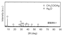
- Preparation Example S1 A 300 ml Erlenmeyer flask was charged with 100 ml of ethanol and subjected to deaeration treatment by irradiating with ultrasonic waves for 30 minutes in a water bath. Thereafter, 2.0 g (8.63 mmol) of silver oxide (Ag 2 O, manufactured by Soekawa Riken) and 1.0 g (16.7 mmol) of acetic acid (CH 3 COOH, manufactured by Wako Pure Chemical Industries, Ltd.) were added. Then, the obtained silver oxide dispersion was irradiated with ultrasonic waves (frequency: 44.4 kHz, output: 100 W) at a temperature of 40 ° C.
- ultrasonic waves frequency: 44.4 kHz, output: 100 W
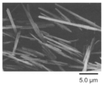
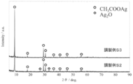
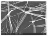
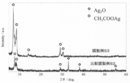
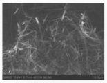
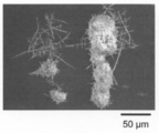
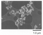
- Preparation Examples S2 to S3 A part of the dispersion obtained in the same manner as in Preparation Example S1 was collected except that the ultrasonic irradiation time was 30 minutes (Preparation Example S2) and 60 minutes (Preparation Example S3), respectively, and the solvent was removed. The powder was recovered. The X-ray diffraction pattern of this powder is also shown in FIG. In addition, a few drops of the dispersion after ultrasonic irradiation were dropped on a carbon reinforced microgrid (manufactured by Oken Shoji Co., Ltd.) and observed with an electron microscope. The result of S2 is shown in FIG. 4, and the result of S3 is shown in FIG.
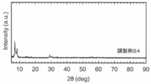
- Preparation Examples S5 to S6 A part of the dispersion obtained in the same manner as in Preparation Example S4 was collected except that the ultrasonic irradiation time was 15 minutes (Preparation Example S5) and 30 minutes (Preparation Example S6), respectively, and the solvent was removed. The powder was recovered. The X-ray diffraction pattern of this powder is also shown in FIG. In addition, a few drops of the dispersion after ultrasonic irradiation were dropped on a carbon reinforced microgrid (manufactured by Oken Shoji Co., Ltd.) and observed with an electron microscope. FIG. 9 shows the result of S5, and FIG. 10 shows the result of S6.
- Preparation Example S7 A dispersion containing silver carboxylate was prepared in the same manner as in Preparation Example S4 except that butyric acid (manufactured by Wako Pure Chemical Industries, Ltd.) was added instead of propionic acid so that the Ag ratio was 0.25 equivalent. . A part of the obtained dispersion was collected to remove the solvent, and the powder was recovered. The X-ray diffraction pattern of this powder is shown in the upper part of FIG. In addition, the upper stage of FIG. 11 also shows the X-ray diffraction pattern of the mixed carboxylic acid silver salt obtained in Preparation Example S4. Moreover, the lower stage of FIG. 11 shows X-ray diffraction patterns of various carboxylic acid silver salts.
- Preparation Example S8 A dispersion containing silver carboxylate was prepared in the same manner as Preparation Example S4 except that valeric acid (manufactured by Wako Pure Chemical Industries, Ltd.) was added instead of propionic acid so that the Ag ratio was 0.25 equivalent. did. A part of the obtained dispersion was collected to remove the solvent, and the powder was recovered. The X-ray diffraction pattern of this powder is shown in the upper part of FIG. In addition, a few drops of the dispersion after ultrasonic irradiation were dropped on a carbon reinforced microgrid (manufactured by Oken Shoji Co., Ltd.) and observed with an electron microscope. The result is shown in FIG.
- Preparation Example S9 A dispersion containing silver carboxylate was prepared in the same manner as in Preparation Example S4 except that hexanoic acid (manufactured by Wako Pure Chemical Industries, Ltd.) was added instead of propionic acid so that the Ag ratio was 0.25 equivalent. did. A part of the obtained dispersion was collected to remove the solvent, and the powder was recovered. The X-ray diffraction pattern of this powder is shown in the upper part of FIG. In addition, a few drops of the dispersion after ultrasonic irradiation were dropped on a carbon reinforced microgrid (manufactured by Oken Shoji Co., Ltd.) and observed with an electron microscope. The result is shown in FIG.
- the average minor axis length was 100 nm
- the average major axis length was 2.0 ⁇ m
- the average aspect ratio was 20, and it was fibrous.
- the average minor axis length, average major axis length, and average value of the aspect ratio of the silver carboxylate obtained in Preparation Example S8 were determined from the SEM photograph in FIG.
- the shaft length was 1.8 ⁇ m
- the average aspect ratio was 12, and it was fibrous. From the SEM photograph of FIG.
- the average minor axis length, average major axis length, and average value of the aspect ratio of the silver carboxylate obtained in Preparation Example S9 were determined.
- the average minor axis length was 60 nm and the average length.
- the shaft length was 0.9 ⁇ m, the average aspect ratio was 15, and it was fibrous.
- Preparation Example M1 Contains fibrous particles (average minor axis length: 0.829 ⁇ m, average major axis length: 9.64 ⁇ m, average aspect ratio: 11.6) obtained from Preparation Example S1 as nuclei
- the ethanol dispersion to be transferred is transferred to a 300 ml three-necked flask, and a Teflon (registered trademark) rugby ball-type stirrer is placed therein.
- a Teflon (registered trademark) rugby ball-type stirrer was placed therein.
- microwaves frequency: 2.45 GHz, output: 300 W
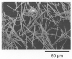
- several drops of the obtained dispersion liquid were dropped on a carbon reinforced microgrid (manufactured by Oken Shoji Co., Ltd.) and observed with an electron microscope. The result is shown in FIG.
- Preparation Example M2 Instead of the fibrous particles made of silver acetate obtained in Preparation Example S1, fibrous particles made of mixed silver carboxylate obtained in Preparation Example S6 (average minor axis length: 0.18 ⁇ m, average major axis length) The number of dispersions obtained in the same manner as in Preparation Example M1, except that 3.2 ⁇ m and the average aspect ratio: 17) were used as cores in a carbon-reinforced microgrid (Oken Corporation) The solution was dropped and observed with an electron microscope. The result is shown in FIG.
- Example 1 Ethanol dispersion liquid containing acicular silver acetate obtained in Preparation Example M1 (average minor axis length: 1.73 ⁇ m, average major axis length: 25.8 ⁇ m, average aspect ratio: 14.9) 1 ml was applied on a glass substrate (2.6 cm ⁇ 7.6 cm), and ethanol was removed by drying to form a film. A petri dish (inner diameter) of this acicular silver acetate film and filter paper (2 cm ⁇ 4 cm) sufficiently impregnated with hydrazine monohydrate (N 2 H 4 .H 2 O, manufactured by Wako Pure Chemical Industries, Ltd.) : 8 cm) and covered, heated on a hot plate set at 80 ° C.
- hydrazine monohydrate N 2 H 4 .H 2 O, manufactured by Wako Pure Chemical Industries, Ltd.
- Example 2 Except for changing the heating time (reduction time) to 180 seconds, acicular silver acetate was subjected to solid-gas reduction in the same manner as in Example 1 to obtain a powder. SEM photographs of this powder are shown in FIGS. 24A and 24B.
- Example 3 Except for changing the heating temperature (reduction temperature) to 60 ° C., acicular silver acetate was subjected to solid-gas reduction in the same manner as in Example 1 to obtain a powder. An SEM photograph of this powder is shown in FIG.
- Example 4 Except for changing the heating temperature (reduction temperature) to 100 ° C., acicular silver acetate was subjected to solid-gas reduction in the same manner as in Example 1 to obtain a powder. An SEM photograph of this powder is shown in FIG.
- Example 5 Except for changing the heating temperature (reduction temperature) to 100 ° C., acicular silver acetate was subjected to solid-gas reduction in the same manner as in Example 2 to obtain a powder. An SEM photograph of this powder is shown in FIG.
- the silver wire (Example 1) obtained by the solid-gas reduction treatment at 80 ° C. for 60 seconds retains the shape (needle shape) of silver acetate before the reduction treatment. It was.
- the silver wire had an average minor axis length of 1359 nm, an average major axis length of 17.17 ⁇ m, and an average aspect ratio of 12.56.
- the silver wire obtained in Example 1 was a porous wire in which silver nanoparticles having an average particle diameter of 20 nm were connected.
- the obtained porous silver wire is a cylinder
- the average minor axis length is the cross-sectional diameter of the cylinder
- the average major axis length is the length of the cylinder
- the volume of this cylinder is calculated
- the porous The theoretical volume of the nonporous silver wire having the same mass as the porous silver wire was calculated, and the theoretical porosity determined from the mass of the porous silver wire was calculated from this theoretical volume and the volume of the cylinder.
- the theoretical porosity determined from the mass of the porous silver wire obtained in Example 1 was 32.0%.
- the silver wire (Example 2) obtained by the solid-gas reduction treatment at 80 ° C. for 180 seconds holds the shape (needle shape) of silver acetate before the reduction treatment. It was.
- the silver wire had an average minor axis length of 1310 nm, an average major axis length of 17.06 ⁇ m, and an average aspect ratio of 13.02.
- the silver wire obtained in Example 2 was a porous wire in which silver nanoparticles having an average particle diameter of 30 nm were connected.
- the silver wire (Example 3) obtained by solid-gas reduction treatment at 60 ° C. for 60 seconds is a porous wire in which silver nanoparticles having an average particle diameter of 28 nm are connected. It was confirmed that.
- the silver wire had an average minor axis length of 1452 nm, an average major axis length of 18.21 ⁇ m, and an average aspect ratio of 12.54.
- the silver wire (Example 4) obtained by the solid-gas reduction treatment at 100 ° C. for 60 seconds is a porous wire in which silver nanoparticles having an average particle diameter of 65 nm are connected. It was confirmed that. Further, this silver wire had an average minor axis length of 1237 nm, an average major axis length of 18.31 ⁇ m, and an average aspect ratio of 14.8.
- the silver wire (Example 5) obtained by the solid-gas reduction treatment at 100 ° C. for 180 seconds is a porous wire in which silver nanoparticles having an average particle diameter of 85 nm are connected. It was confirmed that.
- the silver wire had an average minor axis length of 1187 nm, an average major axis length of 17.95 ⁇ m, and an average aspect ratio of 15.1.
- Example 6 In place of the acicular silver acetate obtained in Preparation Example M1, the fibrous mixed carboxylate obtained in Preparation Example S4 (average minor axis length: 120 nm, average major axis length: 1.706 ⁇ m, aspect ratio) A film was formed in the same manner as in Example 1 except that 0.1 ml of an ethanol (100%) dispersion solution containing 16.03) was used. The film made of the mixed carboxylate was subjected to solid-gas reduction using hydrazine. Thereafter, the membrane was sufficiently dried and collected as a powder. SEM photographs of this powder are shown in FIGS. 28A and 28B.
- Example 7 Ethanol (100%) containing fibrous mixed silver carboxylate obtained in Preparation Example S4 (average minor axis length: 120 nm, average major axis length: 1.706 ⁇ m, average aspect ratio: 16.03) ) 0.1 ml of the dispersion was spray-coated on a glass substrate (2.6 cm ⁇ 7.6 cm) heated to 80 ° C., and ethanol was removed by drying to form a film. After film formation, a solid-gas reduction treatment was performed on the film made of the fibrous mixed carboxylate using hydrazine in the same manner as in Example 1 except that the heating temperature (reduction temperature) was 100 ° C. Thereafter, the membrane was sufficiently dried and collected as a powder. SEM photographs of this powder are shown in FIGS. 29A and 29B.
- Example 8 A film made of silver wire was prepared in the same manner as in Example 7 except that the solvent of the dispersion was changed to ethanol (100%) and a toluene / ethanol mixture (toluene: 50% by volume, ethanol: 50% by volume) was used. Produced. When the electrical resistivity (thickness 1 ⁇ m) and light transmittance of the obtained film were measured, it was confirmed that the film had excellent conductivity of 63.8 ⁇ / sq at a light transmittance of 74.78%.
- the membrane was sufficiently dried and collected as a powder. SEM photographs of this powder are shown in FIGS. 30A and 30B. From the SEM photographs of FIGS. 30A to 30B, it was found that the shape of the mixed silver carboxylate before the reduction treatment was maintained not only when ethanol was used as the solvent but also when toluene was used (Example 8). It was. Further, the obtained silver wire had an average minor axis length of 52 nm, an average major axis length of 0.63 ⁇ m, and an average aspect ratio of 12.1. Moreover, it was confirmed that the obtained silver wire was a porous thing which the silver nanoparticle with an average particle diameter of 50 nm connected.
- Example 7 From the results of Example 7, it was confirmed that the aggregation of particles was further suppressed by adding toluene as a solvent. This is presumably because the evaporation rate was increased by replacing part of the solvent with toluene.
- Example 9 A film made of silver wire was produced in the same manner as in Example 6 except that the heating time (reduction time) was changed to 30 seconds. Thereafter, the membrane was sufficiently dried and collected as a powder.
- Example 10 A film made of silver wire was produced in the same manner as in Example 6 except that the heating time (reduction time) was changed to 30 seconds and the heating temperature (reduction temperature) was changed to 100 ° C. Thereafter, the membrane was sufficiently dried and collected as a powder.
- Example 11 A film made of silver wire was prepared in the same manner as in Example 6 except that the solvent of the dispersion was changed to ethanol (100%) and a toluene / ethanol mixed solution (toluene: 50% by volume, ethanol: 50% by volume) was used. Produced. Thereafter, the membrane was sufficiently dried and collected as a powder.
- Example 12 A silver wire was obtained in the same manner as in Example 6 except that a 2-propanol / ethanol mixed solution (2-propanol: 50% by volume, ethanol: 50% by volume) was used instead of ethanol (100%) as a solvent in the dispersion.
- a 2-propanol / ethanol mixed solution (2-propanol: 50% by volume, ethanol: 50% by volume) was used instead of ethanol (100%) as a solvent in the dispersion.
- membrane which consists of was produced. Thereafter, the membrane was sufficiently dried and collected as a powder.
- Example 13 A film made of silver wire was prepared in the same manner as in Example 6 except that the solvent of the dispersion was changed to ethanol (100%) and a water / ethanol mixture (water: 20% by volume, ethanol: 80% by volume) was used. Produced. Thereafter, the membrane was sufficiently dried and collected as a powder.
- Example 14 Needle-like mixed carboxylate obtained in Preparation Example M2 instead of the fibrous mixed carboxylate obtained in Preparation Example S4 (average minor axis length: 0.172 nm, average major axis length: 2.35 ⁇ m) The average value of the aspect ratio: 15.1) was used except that the film was formed in the same manner as in Example 1, and hydrazine was added to the fibrous mixed carboxylate film in the same manner as in Example 1. A solid-gas reduction treatment was performed. Thereafter, the membrane was sufficiently dried and collected as a powder.
- Example 15 A film was formed in the same manner as in Example 6 using 0.1 ml of an ethanol (100%) dispersion containing the needle-shaped mixed silver carboxylate (raw material) obtained in Preparation Example S4, and this fibrous mixed carboxylic acid Plasma reduction treatment was performed on the film made of silver.
- the conditions for the plasma reduction treatment were microwave output: 85 W, plasma irradiation time: 180 seconds, and Ar gas flow rate: 50 L / min or less. Thereafter, the membrane was sufficiently dried and collected as a powder. The X-ray diffraction pattern of this powder is shown in FIG. In addition, SEM photographs of the obtained powder are shown in FIGS. 32A and 32B.
- the silver wire (Example 15) obtained by the plasma reduction treatment retained the shape of the mixed silver carboxylate before the reduction treatment.
- the silver wire had an average minor axis length of 60 nm, an average major axis length of 0.82 ⁇ m, and an average aspect ratio of 13.7. Furthermore, it was confirmed that the silver wire obtained in Example 15 is a porous wire in which silver nanoparticles having an average particle diameter of 58 nm are connected.
- Example 16 A film made of silver wire was prepared in the same manner as in Example 15 except that the microwave power for plasma reduction was changed to 71.5 W and the plasma irradiation time was changed to 60 seconds. Thereafter, the membrane was sufficiently dried and collected as a powder. SEM photographs of the obtained powder are shown in FIGS. 33A and 33B.
- Example 17 A film made of silver wire was produced in the same manner as in Example 15 except that the microwave power for plasma reduction was changed to 71.5 W. Thereafter, the membrane was sufficiently dried and collected as a powder. SEM photographs of the obtained powder are shown in FIGS. 34A and 34B.
- Example 18 A film made of silver wire was produced in the same manner as in Example 15 except that the microwave power for plasma reduction was changed to 162 W and the plasma irradiation time was changed to 60 seconds. Thereafter, the membrane was sufficiently dried and collected as a powder. SEM photographs of the obtained powder are shown in FIGS. 35A and 35B.
- Example 19 A film made of silver wire was produced in the same manner as in Example 15 except that the microwave output for plasma reduction was changed to 162 W. Thereafter, the membrane was sufficiently dried and collected as a powder. SEM photographs of the obtained powder are shown in FIGS. 36A and 36B.
- Example 6 For the metal wires obtained in Example 6, Examples 9 to 14, and Examples 16 to 19, the measurement porosity determined from the projected area was measured. The results are shown in Table 1. From the results shown in Table 1, it was confirmed that the measured porosity determined from the projected area was between 11 and 31%.
- Example 2 In the same manner as in Example 6, a film made of the fibrous mixed silver carboxylate was formed on a glass substrate. This glass substrate is placed on a hot plate set at 80 ° C., and an acetone solution containing 1.0% by mass of hydrazine monohydrate (N 2 H 4 .H 2 O, manufactured by Wako Pure Chemical Industries, Ltd.) Was dropped onto the film made of fibrous mixed silver carboxylate and heated for 3 minutes to reduce the fibrous mixed silver carboxylate. Thereafter, the membrane was sufficiently dried and collected as a powder. An SEM photograph of this powder is shown in FIG.
- Example 20 A film (thickness: 5 ⁇ m) made of silver wire was produced in the same manner as in Example 6. A photograph of the membrane is shown in FIG. Further, the electrical resistivity and light transmittance of the film were measured. FIG. 41 shows the relationship between the electrical resistivity and the light transmittance at a wavelength of 550 nm.
- Example 21 A film made of silver wire was produced in the same manner as in Example 6 except that the heating time (reduction time) was changed to 180 seconds (Example 21) and 300 seconds (Example 22). A photograph of the obtained film is shown in FIG. 42 together with the film obtained in Example 6. From the results of FIG. 42, it was found that the light transmittance of the film can be adjusted also by reducing conditions.
- Example 23 Ethanol dispersion 0 containing the fibrous mixed silver carboxylate obtained in Preparation Example S4 (average minor axis length: 120 nm, average major axis length: 1.706 ⁇ m, average aspect ratio: 16.3) .1 ml was applied on a polycarbonate substrate (“PCSMPS610” manufactured by Takiron Co., Ltd., 2.6 cm ⁇ 2.6 cm, thickness 500 ⁇ m) heated to 80 ° C., and ethanol was removed by drying at 80 ° C.
- PCSMPS610 polycarbonate substrate
- the fibrous mixed silver carboxylate was subjected to solid-gas reduction treatment using hydrazine, and the silver wire, the polycarbonate substrate, A composite comprising The SEM photograph of the surface where the silver wire of this composite_body
- positioned is shown to FIG. 43A, FIG. 43B and FIG. 43C.
- Example 24 Composites each including a silver wire and a polycarbonate substrate were obtained in the same manner as in Example 23, except that the heating time (reduction time) was 30, 60, 90, and 120 seconds.
- the electrical resistivity (Rs: resistance [ ⁇ / sec]) and light transmittance (T: transmission [%]) were measured, and the relationship between the two was plotted.
- the results are shown in FIG.
- the result of FIG. 44 confirms that the composite can be used as a transparent conductor, and the performance of the transparent conductor, that is, a good balance between electrical resistivity and light transmittance, can be adjusted by reducing conditions. I found it possible.
- FIG. 45 shows an SEM photograph of the cross section of the composite obtained with a reduction time of 120 seconds
- FIG. 46 shows an SEM photograph of the cross section of the polycarbonate substrate before film formation as a reference.
- FIGS. 48A and 48B show the BSE image and SE image of the surface of the composite obtained with a reduction time of 90 seconds where no blackening was observed (coating liquid coating surface, the same applies hereinafter), respectively.
- FIGS. 48A and 48B show BSE photographs and SE photographs of the surface of the portion where blackening was observed. Furthermore, the results of observation with a laser microscope on the surface of the composite obtained at a reduction time of 30, 90, and 120 seconds are shown in FIGS. 49A and B, FIGS. 50A and B, and FIGS. 51A and 51B, respectively (A: Laser micrograph of surface, B: sectional view). Note that FIG. 50 shows an observation of a boundary portion between a portion where blackening was not observed and a portion where blackening was observed.
- Example 25 Instead of the acicular silver acetate obtained in Preparation Example M1, plate-like copper acetate (I) anhydride (manufactured by Wako Pure Chemical Industries, Ltd., average minor axis length: 15 ⁇ m, average major axis length: 50 ⁇ m, aspect ratio) A film was formed in the same manner as in Example 1 except that 3.3) was used. After film formation, Ar—H 2 gas (H 2 concentration: 2.01% by volume) was circulated in a container in which the film made of plate copper acetate was allowed to stand, and heated at 500 ° C. to form the plate copper acetate. The solid was reduced. Thereafter, the membrane was sufficiently dried and collected as a powder. The X-ray diffraction pattern of this powder is shown in FIG. In addition, SEM photographs of the obtained powder are shown in FIGS. 53A to 53D, and an SEM photograph of the copper (I) acetate anhydride used is shown in FIG.
- the obtained copper wire retains the shape of copper acetate before the reduction treatment, and is a porous one in which copper nanoparticles having an average particle diameter of 100 nm are connected.
- the copper wire had an average minor axis length of 10 ⁇ m, an average major axis length of 35 ⁇ m, and an average aspect ratio of 3.5.
- porous metal nanowires and metal microwires can be produced relatively easily without using additives such as a protective agent and a template. Therefore, even when the porous metal wire of the present invention is used as a material for a transparent conductive film, it is not necessary to remove additives such as a protective agent and a template, and since it has a high aspect ratio, It is useful as a material for a transparent conductive film replacing ITO.
Landscapes
- Chemical & Material Sciences (AREA)
- Engineering & Computer Science (AREA)
- Nanotechnology (AREA)
- Organic Chemistry (AREA)
- Inorganic Chemistry (AREA)
- Chemical Kinetics & Catalysis (AREA)
- General Chemical & Material Sciences (AREA)
- Oil, Petroleum & Natural Gas (AREA)
- Manufacture Of Metal Powder And Suspensions Thereof (AREA)
- Powder Metallurgy (AREA)
- Non-Insulated Conductors (AREA)
- Manufacturing Of Electric Cables (AREA)
- Organic Low-Molecular-Weight Compounds And Preparation Thereof (AREA)
Abstract
繊維状の有機金属塩を還元することにより、金属ナノ粒子が連結している多孔質金属ワイヤーを形成させる工程を含み、 前記還元が、プラズマ還元、光還元、レーザー照射還元、及び、前記有機金属塩と気体状の還元剤とを接触させる固気還元からなる群から選択されるいずれか一種である多孔質金属ワイヤーの製造方法。
Description
本発明は、多孔質金属ワイヤー、それを含有する膜、及びそれらの製造方法に関し、より詳しくは、透明導電膜に好適に利用可能な多孔質金属ナノワイヤー又は多孔質金属マイクロワイヤー、繊維状の有機金属塩を用いた多孔質金属ワイヤーの製造方法、多孔質金属ワイヤーを含有する膜、複合体、及びそれらの製造方法、並びに、繊維状の有機金属塩の製造方法に関する。
酸化インジウムスズ(ITO)に代わる透明導電膜を構成するための材料として、銀ナノワイヤーが注目されている(例えば、特開2009-299162号公報(特許文献1))。従来の銀ナノワイヤーの製造方法としては、例えば、保護剤を用いて銀の(100)面を被覆し、(111)面のみを特異的に成長(異方成長)させる方法(Y.Sunら(非特許文献1))や、カーボンナノチューブ等のテンプレート中で銀イオンを還元する方法等が知られている。しかしながら、従来の銀ナノワイヤーの製造方法では、保護剤やテンプレート等の添加剤が必要であり、また、得られた銀ナノワイヤーを透明導電膜の材料として使用する場合には、これらの添加剤を十分に除去する必要があった。このため、従来の銀ナノワイヤーの製造方法では、製造コストの面で問題があり、また、除去後の添加剤の廃棄処理の問題もあった。
Y.Sunら、Nano Letters、2003年、第3巻、955-960頁
本発明は、上記従来技術の有する課題に鑑みてなされたものであり、保護剤やテンプレート等の添加剤を使用せずに、比較的簡便に多孔質の金属ナノワイヤーや金属マイクロワイヤーを製造することが可能な方法を提供することを目的とする。
本発明者らは、上記目的を達成すべく鋭意研究を重ねた結果、繊維状の有機金属塩を、プラズマ還元、光還元、レーザー照射還元、及び、前記繊維状の有機金属塩と気体状の還元剤とを接触させる固気還元からなる群から選択されるいずれか一種により還元することによって多孔質の金属ナノワイヤーや金属マイクロワイヤーが得られることを見出し、本発明を完成するに至った。
すなわち、本発明の多孔質金属ワイヤーの製造方法は、繊維状の有機金属塩を還元することにより、金属ナノ粒子が連結している多孔質金属ワイヤーを形成させる工程を含み、
前記還元が、プラズマ還元、光還元、レーザー照射還元、及び、前記繊維状の有機金属塩と気体状の還元剤とを接触させる固気還元からなる群から選択されるいずれか一種であるものである。
前記還元が、プラズマ還元、光還元、レーザー照射還元、及び、前記繊維状の有機金属塩と気体状の還元剤とを接触させる固気還元からなる群から選択されるいずれか一種であるものである。
本発明の多孔質金属ワイヤーの製造方法において、前記還元が固気還元である場合、前記還元剤としては、ヒドラジン、水素化ホウ素ナトリウム、ジボラン及び水素からなる群から選択される少なくとも1種が好ましい。
本発明の多孔質金属ワイヤーの製造方法において、前記還元がプラズマ還元である場合、前記プラズマ還元が、Ar、He、N2からなる群から選択される少なくとも1種のガスにマイクロ波を照射して発生させたプラズマによる還元であることが好ましい。
また、前記繊維状の有機金属塩としては、カルボン酸金属塩が好ましく、酢酸金属塩、プロピオン酸金属塩、酪酸金属塩、吉草酸金属塩及びヘキサン酸金属塩からなる群から選択される少なくとも1種がより好ましい。
さらに、本発明の多孔質金属ワイヤーの製造方法においては、前記繊維状の有機金属塩を形成する工程として、金属化合物及び有機酸を含有する溶液に大気中で超音波を照射する工程や、金属化合物及び有機酸を含有する溶液に大気中で超音波を照射して有機金属塩からなる核を形成し、前記有機金属塩からなる核を含有する分散液にマイクロ波を照射して前記核を異方粒成長させる工程が更に含まれていてもよい。また、前記金属化合物としては、金属酸化物であることが好ましい。
本発明の多孔質金属ワイヤーは、金属ナノ粒子が連結してなるものである。前記多孔質金属ワイヤーとしては、前記多孔質金属ワイヤーについて、走査型電子顕微鏡によって前記多孔質金属ワイヤーの平均短軸長さを短辺、前記平均短軸長さの2倍の長さを長辺とする微小分析範囲における空隙の投影面積の割合を測定して得られる空隙率の平均が1~50%であることが好ましい。
さらに、この多孔質金属ワイヤーにおいて、前記金属ナノ粒子の平均粒子径としては10~100nmが好ましく、また、アスペクト比(長軸長さ/短軸長さ)の平均値としては8~25が好ましい。
本発明の膜は、前記本発明の多孔質金属ワイヤーを含有するものである。この膜においては、前記多孔質金属ワイヤー同士が金属結合していることが好ましい。
また、本発明の複合体は、ポリカーボネートを含有する基板と前記本発明の多孔質金属ワイヤーとを備えるものである。
本発明の膜の製造方法は、繊維状の有機金属塩及び溶媒を含有する塗工液を基板上に塗布する工程と、前記溶媒を除去する工程と、前記有機金属塩を還元することにより、金属ナノ粒子が連結している多孔質金属ワイヤーを含有する膜を形成させる工程とを含み、
前記還元が、プラズマ還元、光還元、レーザー照射還元、及び、前記繊維状の有機金属塩と気体状の還元剤とを接触させる固気還元からなる群から選択されるいずれか一種であるものである。
前記還元が、プラズマ還元、光還元、レーザー照射還元、及び、前記繊維状の有機金属塩と気体状の還元剤とを接触させる固気還元からなる群から選択されるいずれか一種であるものである。
さらに、本発明の複合体の製造方法は、繊維状の有機金属塩及び溶媒を含有する塗工液をポリカーボネートを含有する基板上に塗布する工程と、前記溶媒を除去する工程と、前記繊維状の有機金属塩を還元することにより、金属ナノ粒子が連結している多孔質金属ワイヤーを形成させ、前記基板と前記多孔質金属ワイヤーとを備える複合体を得る工程とを含み、前記還元が前記繊維状の有機金属塩とヒドラジンとを接触させる固気還元であるものである。
本発明の第一の繊維状の有機金属塩の製造方法は、金属化合物及び有機酸を含有する溶液に大気中で超音波を照射して繊維状の有機金属塩を形成するものである。また、本発明の第二の繊維状の有機金属塩の製造方法は、金属化合物及び有機酸を含有する溶液に大気中で超音波を照射して有機金属塩からなる核を形成し、前記有機金属塩からなる核を含有する分散液にマイクロ波を照射して前記核を異方粒成長させることにより繊維状の有機金属塩を形成するものである。
本発明によれば、保護剤やテンプレート等の添加剤を使用しなくても、比較的簡便に多孔質の金属ナノワイヤーや金属マイクロワイヤーを製造することが可能となる。
以下、本発明をその好適な実施形態に即して詳細に説明する。
先ず、本発明の多孔質金属ワイヤーの製造方法について説明する。本発明の多孔質金属ワイヤーの製造方法は、繊維状の有機金属塩を還元することにより、金属ナノ粒子が連結している多孔質金属ワイヤーを形成させる工程(還元工程)を含み、
前記還元が、プラズマ還元、光還元、レーザー照射還元、及び、前記繊維状の有機金属塩と気体状の還元剤とを接触させる固気還元からなる群から選択されるいずれか一種であるものである。
前記還元が、プラズマ還元、光還元、レーザー照射還元、及び、前記繊維状の有機金属塩と気体状の還元剤とを接触させる固気還元からなる群から選択されるいずれか一種であるものである。
(還元工程)
本発明にかかる還元工程は、プラズマ還元、光還元、レーザー照射還元、及び、前記繊維状の有機金属塩と気体状の還元剤とを接触させる固気還元からなる群から選択されるいずれか一種により前記繊維状の有機金属塩を還元するものである。これらの還元により、有機金属塩の繊維形状を損なうことなく、所望の金属ワイヤーを得ることができる。また、この還元処理により有機金属塩を形成していた有機酸残基が除去されるため、繊維状の有機金属塩中の有機酸残基が存在していた部分には細孔が形成され、得られる金属ワイヤーは多孔質構造となる。さらに、この多孔質金属ワイヤーは金属ナノ粒子が連結した構造を形成したものとなる。また、得られる金属ワイヤーはこのように金属ナノ粒子が連結した多孔質構造を形成しているため、表面に凹凸形状を有するものとなる。さらに、本発明の多孔質金属ワイヤーの製造方法において、部分的に重なりあった状態に配置されている繊維状の有機金属塩を還元した場合には、前記繊維状の有機金属塩よりも長軸長さが長い金属ワイヤーを得ることができる。また、本発明の多孔質金属ワイヤーを含む膜の製造方法において、部分的に重なりあった状態に配置されている繊維状の有機金属塩を還元した場合には、前記多孔質金属ワイヤー同士が金属結合した膜を得ることができる。
本発明にかかる還元工程は、プラズマ還元、光還元、レーザー照射還元、及び、前記繊維状の有機金属塩と気体状の還元剤とを接触させる固気還元からなる群から選択されるいずれか一種により前記繊維状の有機金属塩を還元するものである。これらの還元により、有機金属塩の繊維形状を損なうことなく、所望の金属ワイヤーを得ることができる。また、この還元処理により有機金属塩を形成していた有機酸残基が除去されるため、繊維状の有機金属塩中の有機酸残基が存在していた部分には細孔が形成され、得られる金属ワイヤーは多孔質構造となる。さらに、この多孔質金属ワイヤーは金属ナノ粒子が連結した構造を形成したものとなる。また、得られる金属ワイヤーはこのように金属ナノ粒子が連結した多孔質構造を形成しているため、表面に凹凸形状を有するものとなる。さらに、本発明の多孔質金属ワイヤーの製造方法において、部分的に重なりあった状態に配置されている繊維状の有機金属塩を還元した場合には、前記繊維状の有機金属塩よりも長軸長さが長い金属ワイヤーを得ることができる。また、本発明の多孔質金属ワイヤーを含む膜の製造方法において、部分的に重なりあった状態に配置されている繊維状の有機金属塩を還元した場合には、前記多孔質金属ワイヤー同士が金属結合した膜を得ることができる。
本発明に用いられる繊維状の有機金属塩としては、所望の金属ワイヤーを構成する金属原子を含有する有機金属塩であって、繊維状のものであれば特に制限はない。なお、本発明において、「繊維状」には、針状、板状、円柱状等の形状を含むものとする。
このような有機金属塩を構成する金属原子としては、例えば、銀原子、金原子、白金原子、銅原子、ニッケル原子、アルミニウム原子、スズ原子が挙げられ、中でも、銀原子、白金原子、銅原子が好ましい。このような金属原子は、1種を単独で使用しても2種以上を併用してもよい。また、有機金属塩の種類としては、金属単体に還元されるものであれば特に制限はないが、例えば、カルボン酸金属塩が好ましく、酢酸金属塩、プロピオン酸金属塩、酪酸金属塩、吉草酸金属塩、ヘキサン酸金属塩がより好ましい。これらの有機金属塩は1種を単独で使用しても2種以上を併用してもよい。また、2種以上の有機金属塩の中間体(好ましくは、二量体等の多量体)は、比較的アスペクト比の大きい繊維状の有機金属塩となるため、このような有機金属塩の中間体を用いることによってアスペクト比の大きい多孔質金属ワイヤーを得ることができる。このような繊維状の有機金属塩としては、市販のものを使用することができるが、後述する方法で製造したものを使用してもよい。
本発明において、繊維状の有機金属塩の平均短軸長さとしては、15μm以下が好ましく、十分にアスペクト比の大きい金属ワイヤーを得るという観点からは5μm以下が好ましく、2μm以下が特に好ましい。繊維状の有機金属塩の平均短軸長さが前記上限を超えると、所望の平均短軸長さの金属ワイヤーが得られない傾向にある。なお、繊維状の有機金属塩の平均短軸長さの下限については特に制限はないが、通常、0.1μm以上である。
また、前記繊維状の有機金属塩の平均長軸長さとしては、1μm以上が好ましく、5μm以上がより好ましく、10μm以上が更に好ましく、15μm以上が特に好ましく、20μm以上が最も好ましい。繊維状の有機金属塩の平均長軸長さが前記下限未満になると、繊維状の有機金属塩のアスペクト比が小さくなり、所望の金属ワイヤーが得られない傾向にある。また、繊維状の有機金属塩の平均長軸長さの上限としては特に制限はないが、通常、50μm以下である。
さらに、前記繊維状の有機金属塩のアスペクト比の平均値としては、3.3以上が好ましく、十分にアスペクト比の大きい金属ワイヤーを得るという観点からは6.5以上が好ましく、9以上がより好ましく、12以上が更に好ましく、14以上が特に好ましい。繊維状の有機金属塩のアスペクト比の平均値が前記下限未満になると、所望のアスペクト比の金属ワイヤーが得られない傾向にある。なお、繊維状の有機金属塩のアスペクト比の平均値の上限としては特に制限はないが、通常、25以下である。
なお、本発明において、繊維状の有機金属塩の長軸長さ、短軸長さ及びアスペクト比(長軸長さ/短軸長さ)は、走査型電子顕微鏡(SEM)による観察によって測定することができ、前記長軸長さとは、前記繊維状の有機金属塩を平面へ投影した場合の長手方向を長軸としたときの該長軸の長さである。また、前記短軸長さとは、前記繊維状の有機金属塩を平面へ投影した場合の前記長軸と直交する方向を短軸としたときの該短軸の長さの最小値のことをいい、該短軸の長さの最大値/最小値が3以上である場合には前記最小値と最大値との平均のことをいう。ただし、前記繊維状の有機金属塩が繊維状である場合、前記長軸とは最長部のことを指し、板状(すなわち角柱状)又は円柱状である場合、前記長軸とは前記角柱又は円柱の高さのことを指し、前記繊維状の有機金属塩が板状である場合、前記短軸とは前記長軸と直行する断面の長手方向を幅、短手方向を厚さとしたときの幅のことをいう。また、平均長軸長さ、平均短軸長さ及び平均アスペクト比とは、任意の100個の繊維状の有機金属塩を抽出し、これらについてそれぞれ測定した長軸長さ、短軸長さ及びアスペクト比の平均のことをいう。
前記固気還元は、繊維状の有機金属塩と気体状の還元剤とを接触させて前記有機金属塩を固気還元するものである。前記固気還元に用いられる還元剤としては、有機金属塩を金属単体に固気還元できるものであれば特に制限はないが、例えば、ヒドラジン、水素化ホウ素ナトリウム、ジボラン、水素が好ましい。このような還元剤は1種を単独で使用しても2種以上を併用してもよい。
本発明にかかる固気還元処理において、繊維状の有機金属塩と気体状の還元剤との接触方法としては特に制限はないが、例えば、液体状の前記還元剤に加熱処理等を施してその蒸気を生成させ、この還元剤蒸気を繊維状の有機金属塩に接触させる方法や、水素等の気体状の還元剤を直接繊維状の有機金属塩に接触させる方法が挙げられる。
本発明にかかる固気還元処理における温度(還元温度)としては、ヒドラジン還元の場合、40~100℃が好ましく、60~100℃がより好ましい。また、水素還元の場合、40~500℃が好ましい。還元温度が前記下限未満になると、有機金属塩が十分に還元されず、金属ワイヤー中に有機金属塩が残存する傾向にあり、他方、前記上限を超えると、金属ワイヤーを構成する金属ナノ粒子が粒成長するため、あるいは還元処理前の有機金属塩の繊維形状を保持することが困難となるため、所望の金属ワイヤーが得られない傾向にある。
また、前記固気還元処理の時間(還元時間)としては、30~300秒間が好ましく、40~300秒間がより好ましく、60~200秒間がさらに好ましい。還元時間が前記下限未満になると、有機金属塩が十分に還元されず、金属ワイヤー中に有機金属塩が残存する傾向にあり、他方、前記上限を超えると、金属ワイヤーを構成する金属ナノ粒子が粒成長し、所望の金属ワイヤーが得られない傾向にある。また、ポリカーボネートを含有する基板と金属ワイヤーとの複合体を形成させる場合には、有機金属塩を十分に還元させ、かつ、金属ワイヤーの前記基板中への拡散が進行しすぎて導電性や光透過率が低下することを抑制する観点から、前記時間(還元時間)としては、40~100秒間が特に好ましく、60~90秒間がとりわけ好ましい。
前記プラズマ還元としては、Ar、He、N2からなる群から選択される少なくとも1種のガスにマイクロ波を照射してプラズマを発生させ、これを繊維状の有機金属塩に照射して前記有機金属塩を還元する方法が挙げられる。本発明にかかるプラズマ還元処理におけるマイクロ波の出力としては、50~200Wが好ましく、70~200Wがより好ましい。マイクロ波の出力が前記下限未満になると、有機金属塩が十分に還元されず、金属ワイヤー中に有機金属塩が残存する傾向にあり、他方、前記上限を超えると、金属ワイヤーを構成する金属ナノ粒子が粒成長するため、あるいは還元処理前の有機金属塩の繊維形状を保持することが困難となるため、空隙率が低下して、所望の金属ワイヤーが得られない傾向にある。
また、本発明にかかるプラズマ還元処理におけるガスの流量としては、1~30L/分が好ましく、10~30L/分がより好ましい。ガスの流量が前記下限未満になると、プラズマを安定して発生せしめることが困難となる傾向にあり、他方、前記上限を超えると、プラズマを十分に発生せしめることが困難となる傾向にある。
また、前記プラズマ還元処理の時間(プラズマ照射時間)としては、10~600秒間が好ましく、120~300秒間がより好ましい。還元時間が前記下限未満になると、有機金属塩が十分に還元されず、金属ワイヤー中に有機金属塩が残存する傾向にあり、他方、前記上限を超えると、金属ワイヤーを構成する金属ナノ粒子が粒成長し、所望の金属ワイヤーが得られない傾向にある。
前記光還元としては、フラッシュライトを繊維状の有機金属塩に照射して前記有機金属塩を還元する方法が挙げられる。本発明にかかる光還元処理においては、フラッシュライトの照射出力が0.5~10J/cm2であることが好ましく、1.5~5J/cm2であることがより好ましい。フラッシュライトの照射出力が前記下限未満になると、有機金属塩が十分に還元されず、金属ワイヤー中に有機金属塩が残存する傾向にあり、他方、前記上限を超えると、金属ワイヤーを構成する金属ナノ粒子が粒成長するため、あるいは還元処理前の有機金属塩の繊維形状を保持することが困難となるため、空隙率が低下して、所望の金属ワイヤーが得られない傾向にある。
また、前記光還元処理の時間(フラッシュライト照射時間)としては、1~50msが好ましく、2~20msがより好ましい。還元時間が前記下限未満になると、有機金属塩が十分に還元されず、金属ワイヤー中に有機金属塩が残存する傾向にあり、他方、前記上限を超えると、金属ワイヤーを構成する金属ナノ粒子が粒成長し、所望の金属ワイヤーが得られない傾向にある。
前記レーザー照射還元としては、レーザー光を繊維状の有機金属塩に照射して前記有機金属塩を還元する方法が挙げられる。本発明にかかるレーザー照射還元処理においては、レーザー光の照射出力が0.1~100Wであることが好ましく、1~50Wであることがより好ましい。レーザー光の照射出力が前記下限未満になると、有機金属塩が十分に還元されず、金属ワイヤー中に有機金属塩が残存する傾向にあり、他方、前記上限を超えると、金属ワイヤーを構成する金属ナノ粒子が粒成長するため、あるいは還元処理前の有機金属塩の繊維形状を保持することが困難となるため、空隙率が低下して、所望の金属ワイヤーが得られない傾向にある。
また、前記レーザー照射還元処理の時間(レーザー照射時間)としては、0.1~100mm/sが好ましく、1~50mm/sがより好ましい。還元時間が前記下限未満になると、有機金属塩が十分に還元されず、金属ワイヤー中に有機金属塩が残存する傾向にあり、他方、前記上限を超えると、金属ワイヤーを構成する金属ナノ粒子が粒成長し、所望の金属ワイヤーが得られない傾向にある。
本発明の製造方法によれば、繊維状の有機金属塩が繊維状の形状を損なうことなく、形状を保持したまま還元され、本発明の多孔質金属ワイヤーを得ることができる。本発明において、繊維状の形状を保持するとは、還元前の繊維状の有機金属塩の短軸長さに対する、得られた多孔質金属ワイヤーの短軸長さの変化量が小さいことをいい、走査型電子顕微鏡(SEM)による観察によって測定することができ、具体的には、還元前の任意の100個の繊維状の有機金属塩の平均短軸長さに対して、得られた任意の100個の多孔質金属ワイヤーの平均短軸長さが、50~100%の範囲内にあることをいう。
(繊維状の有機金属塩の製造方法)
本発明に用いられる繊維状の有機金属塩は、上記の条件を満たすものであれば市販のものを使用してもよいが、金属化合物及び有機酸を含有する溶液に大気中で超音波を照射することによって特にアスペクト比の大きい(好ましくはアスペクト比の平均値が6.5以上、平均短軸長さが2μm以下)繊維状の有機金属塩を、金属や酸化物の生成・混入・残留を抑制しつつ容易に得ることができる。前記金属化合物としては、所望の有機金属塩を構成する金属原子を含有する金属化合物であって、目的とする有機金属塩以外のものであれば特に制限はなく、金属酸化物、無機金属塩、目的とする有機金属塩以外の有機金属塩等が挙げられる。このような金属化合物は1種を単独で使用しても2種以上を併用してもよい。無機金属塩としては、硝酸塩、硫酸塩、シュウ酸塩、塩化物、水酸化物、亜硫酸塩、チオ硫酸塩、過硫酸塩、過硝酸塩、次亜硝酸塩が挙げられる。また、有機金属塩としては、酢酸金属塩、プロピオン酸金属塩、酪酸金属塩、吉草酸金属塩、ヘキサン酸金属塩等のカルボン酸金属塩、スルホン酸金属塩が挙げられる。なお、「目的とする有機金属塩以外の有機金属塩」とは、例えば、目的とする有機金属塩が「酢酸金属塩」の場合には、プロピオン酸金属塩、酪酸金属塩、吉草酸金属塩、ヘキサン酸金属塩等の「酢酸金属塩以外のカルボン酸金属塩」や、スルホン酸金属塩等の「カルボン酸金属塩以外の有機金属塩」を意味する。このような金属化合物のうち、目的とする繊維状の有機金属塩が容易に得られるという観点から、金属酸化物が好ましい。
本発明に用いられる繊維状の有機金属塩は、上記の条件を満たすものであれば市販のものを使用してもよいが、金属化合物及び有機酸を含有する溶液に大気中で超音波を照射することによって特にアスペクト比の大きい(好ましくはアスペクト比の平均値が6.5以上、平均短軸長さが2μm以下)繊維状の有機金属塩を、金属や酸化物の生成・混入・残留を抑制しつつ容易に得ることができる。前記金属化合物としては、所望の有機金属塩を構成する金属原子を含有する金属化合物であって、目的とする有機金属塩以外のものであれば特に制限はなく、金属酸化物、無機金属塩、目的とする有機金属塩以外の有機金属塩等が挙げられる。このような金属化合物は1種を単独で使用しても2種以上を併用してもよい。無機金属塩としては、硝酸塩、硫酸塩、シュウ酸塩、塩化物、水酸化物、亜硫酸塩、チオ硫酸塩、過硫酸塩、過硝酸塩、次亜硝酸塩が挙げられる。また、有機金属塩としては、酢酸金属塩、プロピオン酸金属塩、酪酸金属塩、吉草酸金属塩、ヘキサン酸金属塩等のカルボン酸金属塩、スルホン酸金属塩が挙げられる。なお、「目的とする有機金属塩以外の有機金属塩」とは、例えば、目的とする有機金属塩が「酢酸金属塩」の場合には、プロピオン酸金属塩、酪酸金属塩、吉草酸金属塩、ヘキサン酸金属塩等の「酢酸金属塩以外のカルボン酸金属塩」や、スルホン酸金属塩等の「カルボン酸金属塩以外の有機金属塩」を意味する。このような金属化合物のうち、目的とする繊維状の有機金属塩が容易に得られるという観点から、金属酸化物が好ましい。
また、前記有機酸としては、カルボン酸が好ましく、酢酸、プロピオン酸、酪酸、吉草酸、ヘキサン酸がより好ましく、酢酸が特に好ましい。このような有機酸は1種を単独で使用しても2種以上を併用してもよい。このような有機酸を、前記金属化合物を含有する溶液に添加することによって、未反応の前記金属化合物が残存しにくく、また、副生成物である金属単体の生成を抑制することができ、高純度の有機金属塩粒子(好ましくは、有機金属塩のみからなる粒子)を得ることが可能となる。また、アスペクト比が大きい(好ましくは7以上)繊維状の有機金属塩を得ることができる。なお、本発明において、「粒子」には、「粒状」の形状のみならず、前記「繊維状」の形状を含み、本発明において、前記繊維状とは、アスペクト比が3以上であることをいい、前記粒状とは、前記アスペクト比が3未満であることをいう。ここで、粒子の長軸長さ、短軸長さ及びアスペクト比は、走査型電子顕微鏡(SEM)による観察によって測定することができ、前記長軸長さとは、前記粒子を平面へ投影した場合の長手方向を長軸としたときの該長軸の長さであり、前記短軸長さとは、前記長軸と直交する方向を短軸としたときの該短軸の長さの最小値のことをいい、該短軸の長さの最大値/最小値が3以上である場合には前記最小値と最大値との平均のことをいう。ただし、前記粒子が繊維状である場合、前記長軸とは最長部のことを指し、板状(すなわち角柱状)又は円柱状である場合、前記長軸とは前記角柱又は円柱の高さのことを指し、前記繊維状の有機金属塩が板状である場合、前記短軸とは前記長軸と直行する断面の長手方向を幅、短手方向を厚さとしたときの幅のことをいう。
特に、2種以上の有機酸を併用することによって、比較的アスペクト比の大きい2種以上の有機金属塩の中間体(好ましくは、二量体等の多量体)からなる繊維状の有機金属塩が形成されるため、この繊維状の有機金属塩を固気還元して得られる多孔質金属ワイヤーのアスペクト比も大きくなる傾向にある。
なお、有機酸を添加することによって未反応の前記金属化合物が残存しにくくなる理由は以下のように推察される。すなわち、有機酸を添加することによって前記金属化合物から金属イオンが生成しやすく、混合溶液中の金属イオン濃度が高くなる。このような金属イオン濃度が高い混合溶液においては、金属イオンと有機酸残基との反応が進行しやすいため、未反応の前記金属化合物が残存しにくくなると推察される。
前記金属化合物及び前記有機酸を含有する溶液に用いられる溶媒としては、特に制限はなく、水性溶媒であっても有機溶媒であってもよい。水性溶媒としては水が挙げられ、有機溶媒としてはアルコール(例えば、エタノール等)が挙げられる。このような溶媒は1種を単独で使用しても2種以上を併用してもよい。また、溶媒には予め脱気処理を施すことが好ましい。
本発明に用いられる繊維状の有機金属塩を製造する場合には、先ず、前記金属化合物、有機酸及び溶媒を混合する。得られる混合溶液中の前記金属化合物の濃度としては特に制限はないが、0.001~0.1g/mlが好ましい。前記金属化合物の濃度が前記下限未満になると、有機金属塩の生成量が少なくなり、金属ワイヤーの収率が低下する傾向にあり、他方、前記上限を超えると、粗大な有機金属塩粒子が生成したり、有機金属塩の凝集体が生成しやすく、所望の繊維状の有機金属塩及び金属ワイヤーが得られない傾向にある。
また、有機酸の添加量としては、前記金属化合物1質量部に対して、0.3質量部以上が好ましく、0.4質量部以上がより好ましい。有機酸の添加量が前記下限未満になると、有機酸の添加効果が十分に得られず、未反応の前記金属化合物が残存しやすい傾向にあり、また、得られる有機金属塩粒子のアスペクト比が小さくなりすぎ、超音波照射のみでは所望の繊維状の有機金属塩が得られない傾向にある。一方、有機酸の添加量の上限については特に制限はないが、有機酸の添加効果が飽和する観点から、前記金属化合物1質量部に対して、5質量部以下が好ましく、2質量部以下がより好ましく、1質量部以下が特に好ましい。
次に、前記金属化合物及び有機酸を含有する混合溶液に大気中で超音波を照射する。これにより、前記金属化合物と有機酸とが反応して有機金属塩粒子が生成する。また、超音波を照射することによって、反応初期の核発生を制御したり、反応を促進したりすることができ、さらに、得られる有機金属塩粒子の凝集を抑制することが可能となる。また、本発明においては、前記有機金属塩粒子(繊維状の有機金属塩)を得てからこれを還元するため、超音波の照射環境を還元状態等の特定の環境にする必要がなく、大気中において簡便に繊維状の有機金属塩を得ることができる。
超音波の周波数としては、10~100kHzが好ましく、20~75kHzがより好ましく、30~50kHzが特に好ましい。超音波の周波数が前記下限未満になると、キャビテーションによる腐食力(物理的な破壊力)が強く働いて有機金属塩粒子が分解(切断)され、有機金属塩粒子のアスペクト比が小さくなりすぎ、超音波照射のみでは所望の繊維状の有機金属塩が得られない傾向にある。他方、超音波の周波数が前記上限を超えると、超音波の物理的作用、例えば、攪拌作用が十分に働かず、混合溶液中の前記金属化合物が均一に分散していないため、繊維状の有機金属塩及び金属ワイヤーのアスペクト比にバラつきが生じる傾向にある。
さらに、超音波照射時の混合溶液の温度としては、40~100℃が好ましい。混合溶液の温度が前記下限未満になると、未反応の前記金属化合物が残存しやすい傾向にあり、他方、前記上限を超えると、粗大な核が生成したり、有機金属塩の凝集体が生成しやすく、所望の繊維状の有機金属塩及び金属ワイヤーが得られない傾向にある。また、超音波照射時間としては、5~100分間が好ましく、10~80分間がより好ましく、10~60分間が特に好ましい。超音波照射時間が前記下限未満になると、未反応の前記金属化合物が残存しやすい傾向にあり、他方、前記上限を超えると、粗大な核が生成したり、有機金属塩の凝集体が生成しやすく、所望の繊維状の有機金属塩及び金属ワイヤーが得られない傾向にある。また、超音波の物理的作用により有機金属塩粒子が切断され、有機金属塩粒子のアスペクト比が小さくなりすぎ、超音波照射のみでは所望の繊維状の有機金属塩が得られない傾向にある。
このような超音波処理によって得られる有機金属塩粒子の平均短軸長さとしては、2μm以下が好ましい。前記有機金属塩粒子の平均短軸長さが前記上限を超えると、所望の金属ワイヤーが得られない傾向にある。また、前記有機金属塩粒子の平均短軸長さの下限にとしては特に制限はないが、通常、0.05μm以上である。
また、超音波処理によって得られる有機金属塩粒子の平均長軸長さとしては、0.9μm以上が好ましく、1μm以上がより好ましく、5μm以上が更に好ましく、10μm以上が特に好ましく、15μm以上がとりわけ好ましく、20μm以上が最も好ましい。このような平均長軸長さを有する有機金属塩粒子は、前記固気還元処理において繊維状の有機金属塩として使用することができる。なお、平均長軸長さが前記下限未満の有機金属塩粒子については、後述する加熱処理によって所望の繊維状の有機金属塩とすることができる。また、前記有機金属塩粒子の平均長軸長さの上限にとしては特に制限はないが、通常、30μm以下である。
さらに、超音波処理によって得られる有機金属塩粒子としては、繊維状であることが好ましく、そのアスペクト比の平均値としては6.5以上が好ましく、9以上がより好ましく、12以上が更に好ましく、14以上が特に好ましい。このようなアスペクト比を有する有機金属塩粒子は、前記固気還元処理において繊維状の有機金属塩として使用することができる。なお、アスペクト比の平均値が前記下限未満の有機金属塩粒子については、後述する加熱処理によって所望の繊維状の有機金属塩とすることができる。また、前記有機金属塩粒子のアスペクト比の平均値の上限としては特に制限はないが、通常、25以下である。
このように、本発明に用いられる繊維状の有機金属塩は、前記金属化合物及び有機酸を含有する溶液に超音波を照射することによって得ることができるが、得られた繊維状の有機金属塩に加熱処理を施すことによって、有機金属塩が核となって異方粒成長が起こり、繊維状の有機金属塩(有機金属塩からなる核)のアスペクト比をより大きくすることができる。また、超音波照射のみでは所望のアスペクト比を有する有機金属塩粒子が得られない場合でも、超音波照射の後に加熱処理を施すことによって、所望のアスペクト比を有する繊維状の有機金属塩を得ることができる。
前記加熱処理の方法としては特に制限はないが、異方粒成長が起こり、反応が促進されることによって比較的容易に有機金属塩粒子のアスペクト比を大きくすることができるという観点から、有機金属塩粒子(有機金属塩からなる核)を含有する分散液にマイクロ波を照射する方法が好ましい。マイクロ波以外の加熱方法としては、通常の加熱処理が挙げられ、加熱温度、加熱時間等を適宜調整することによって大きいアスペクト比を有する繊維状の有機金属塩を得ることができる。
前記加熱処理に用いられるマイクロ波の周波数としては特に制限はないが、通常、1~50GHzである。また、マイクロ波照射時の分散液の温度としては、50~100℃が好ましい。分散液の温度が前記下限未満になると、異方粒成長が十分に起こらず、繊維状の有機金属塩のアスペクト比が小さくなり、所望の金属ワイヤーが得られない傾向にあり、他方、前記上限を超えると、マイクロ波により有機金属塩が熱分解して繊維状の有機金属塩のアスペクト比が小さくなり、所望の金属ワイヤーが得られない傾向にある。
マイクロ波照射時間としては、5~200分間が好ましく、15~100分間がより好ましく、30~60分間が特に好ましい。マイクロ波照射時間が前記下限未満になると、異方粒成長が十分に起こらず、繊維状の有機金属塩のアスペクト比が小さくなり、所望の金属ワイヤーが得られない傾向にあり、他方、前記上限を超えると、マイクロ波により有機金属塩が熱分解して繊維状の有機金属塩のアスペクト比が小さくなり、所望の金属ワイヤーが得られない傾向にある。
(多孔質金属ワイヤー)
次に、本発明の多孔質金属ワイヤーについて説明する。本発明の多孔質金属ワイヤーは、金属ナノ粒子が連結してなり、10μm以下、十分にアスペクト比が大きくなるという観点からは20~5000nm、好ましくは20~2000nm、より好ましくは30~1800nm、さらに好ましくは50~1500nmの平均短軸長さを有するものである。特に、本発明の多孔質金属ワイヤーは、金属ナノ粒子が連結した構造のみからなるものであり、保護剤やテンプレート等の添加剤に由来する構造を含んでいない。さらに、本発明の多孔質金属ワイヤーは、このように金属ナノ粒子が連結した多孔質構造を形成しているため、表面に凹凸形状を有するものとなる。このような多孔質金属ワイヤーは、前述した本発明の多孔質金属ワイヤーの製造方法によって得ることができる。
次に、本発明の多孔質金属ワイヤーについて説明する。本発明の多孔質金属ワイヤーは、金属ナノ粒子が連結してなり、10μm以下、十分にアスペクト比が大きくなるという観点からは20~5000nm、好ましくは20~2000nm、より好ましくは30~1800nm、さらに好ましくは50~1500nmの平均短軸長さを有するものである。特に、本発明の多孔質金属ワイヤーは、金属ナノ粒子が連結した構造のみからなるものであり、保護剤やテンプレート等の添加剤に由来する構造を含んでいない。さらに、本発明の多孔質金属ワイヤーは、このように金属ナノ粒子が連結した多孔質構造を形成しているため、表面に凹凸形状を有するものとなる。このような多孔質金属ワイヤーは、前述した本発明の多孔質金属ワイヤーの製造方法によって得ることができる。
本発明の多孔質金属ワイヤーにおいて、平均短軸長さが前記下限未満になると、金属ワイヤーの機械強度が低下して切断されやすくなり、透明導電膜に使用した場合に膜の導電性が低下する傾向にあり、他方、前記上限を超えると、透明導電膜に使用した場合に膜の透明性が低下する傾向にある。
また、本発明の多孔質金属ワイヤーの平均長軸長さとしては、0.5μm以上が好ましく、1μm以上がより好ましく、5μm以上が更に好ましく、10μm以上が特に好ましく、15μm以上が最も好ましい。多孔質金属ワイヤーの平均長軸長さが前記下限未満になると、多孔質金属ワイヤーのアスペクト比が小さくなり、透明導電膜に使用した場合に膜の導電性が低下する傾向にある。また、多孔質金属ワイヤーの平均長軸長さの上限としては特に制限はないが、通常、35μm以下(好ましくは30μm以下)である。
さらに、本発明の多孔質金属ワイヤーのアスペクト比の平均値としては3.5以上、十分にアスペクト比が大きいという観点からは8以上が好ましく、10以上がより好ましく、12以上が更に好ましく、14以上が特に好ましい。多孔質金属ワイヤーのアスペクト比の平均値が前記下限未満になると、透明導電膜に使用した場合に膜の透明性が低下する傾向にある。また、多孔質金属ワイヤーのアスペクト比の平均値の上限については特に制限はないが、通常、25以下である。
なお、本発明において、前記多孔質金属ワイヤーの平均長軸長さ、平均短軸長さ及び平均アスペクト比は、それぞれ、前記繊維状の有機金属塩の平均長軸長さ、平均短軸長さ及び平均アスペクト比と同様にして求めることができる。
また、本発明の多孔質金属ワイヤーを構成する金属ナノ粒子としては、粒状であることが好ましく、その平均粒子径としては、100nm以下が好ましく、75nm以下がより好ましく、50nm以下が特に好ましい。金属ナノ粒子の平均粒子径が前記下限未満になると、透明導電膜に使用する場合に多孔質金属ワイヤーを低温で焼結することが困難となる傾向にある。また、金属ナノ粒子の平均粒子径の下限としては特に制限はないが、通常、10nm以上である。なお、本発明において、前記金属ナノ粒子の粒子径は走査型電子顕微鏡(SEM)による観察によって測定することができ、前記粒子径とは、粒子を平面へ投影した場合の円の直径であり、投影面が円形ではない場合には、その外接円の直径のことをいう。また、金属ナノ粒子の平均粒子径とは、任意の100個の金属ナノ粒子を抽出し、これらの各粒子について測定した粒子径の平均のことをいう。
本発明の多孔質金属ワイヤーとしては、金属ナノ粒子が長軸方向以外の方向にもランダムに連結した構造からなるものであることが好ましく、金属ワイヤーの平均短軸長さよりも小さい粒子径の金属ナノ粒子が充填された構造であることが好ましい。このような多孔質金属ワイヤーの空隙率としては、本発明においては、質量から求められる理論空隙率と、走査型電子顕微鏡を用いた測定によって投影面積から求められる測定空隙率とがある。
前記質量から求められる理論空隙率は、以下のようにして求めることができる。すなわち、還元処理によって得られる多孔質金属ワイヤーの平均短軸長さ及び平均長軸長さを測定する。次に、得られる多孔質金属ワイヤーを円柱と仮定し、前記平均短軸長さを円柱の断面直径、前記平均長軸長さを円柱の長さとして、この円柱の体積を算出する。そして、前記多孔質金属ワイヤーと同質量の非孔質の金属ワイヤーの理論体積を算出し、この理論体積と前記円柱の体積とから多孔質金属ワイヤーの空隙率を算出する。前記質量から求められる理論空隙率としては、10~50%が好ましい。
前記投影面積から求められる測定空隙率は、以下のようにして求めることができる。先ず、上記と同様に多孔質金属ワイヤーの平均短軸長さを測定し、前記平均短軸長さを短辺、前記平均短軸長さの2倍の長さを長辺とする長方形の微小分析範囲を設定する。次いで、SEM写真において観察される金属ワイヤーにこの微小分析範囲をフィッティング、すなわち、金属ワイヤーの短軸方向に前記短辺を、長軸方向に前記長辺を、それぞれあわせ、画像ソフト(例えば、GIMP、The GIMP Development Team製)を用いて前記微小分析範囲内のヒストグラムを作成する。前記微小分析範囲内には空隙の平面への投影部に相当する黒色部とそれ以外(金属粒子)の投影部に相当する白色部とが存在するため、得られるヒストグラムは2極化される。したがって、得られた2極化ヒストグラムの中間値を閾値として、前記微小分析範囲内を黒色部(空隙)と白色部(金属粒子)とに分け、前記微小分析範囲内に黒色部が占める面積の割合を測定する。このように2次元にて測定される黒色部の割合、すなわち空隙の投影面積の割合は、3次元(前記短辺を直径、前記長辺を高さとする円柱)における空隙の割合に近似することができるため、これを投影面積から求められる測定空隙率とする。また、本発明において、前記投影面積から求められる測定空隙率の平均とは、SEM写真で観察される金属ワイヤー上の任意の3箇所の微小分析範囲において求められる前記測定空隙率の平均をいう。前記投影面積から求められる測定空隙率の平均としては、1~50%であることが好ましく、10~30%であることがより好ましい。
(多孔質金属ワイヤーを含有する膜及びその製造方法)
次に、本発明の多孔質金属ワイヤーを含有する膜及びその製造方法について説明する。本発明の膜は、前記本発明の多孔質金属ワイヤーを含有する。この膜は、繊維状の有機金属塩及び溶媒を含有する塗工液を基板上に塗布する工程(塗布工程)と、前記溶媒を除去する工程(溶媒除去工程)と、前記有機金属塩を還元することにより、金属ナノ粒子が連結している多孔質金属ワイヤーを含有する膜を形成させる工程(還元工程)とを含み、
前記還元が、プラズマ還元、光還元、レーザー照射還元、及び、前記有機金属塩と気体状の還元剤とを接触させる固気還元からなる群から選択されるいずれか一種である、本発明の多孔質金属ワイヤーを含有する膜の製造方法によって得ることができる。
前記塗布工程において、前記塗工液は、前記繊維状の有機金属塩と溶媒とを含有するものである。前記繊維状の有機金属塩については前述のとおりである。前記溶媒としては、特に限定されず、例えば、水;アセトン;トルエン;エタノール、2-プロパノール、エチレングリコール等のアルコール類が挙げられ、これらのうちの1種を単独で用いても2種以上を組み合わせて用いてもよい。これらの中でも、揮発(或いは蒸発)速度が速いために、繊維状の有機金属塩の凝集が抑制されて得られる多孔質金属ワイヤーの分散性がより向上するという観点から、エタノール、トルエン、及びこれらの混合液が好ましく、エタノールとトルエンとの混合液がより好ましい。
前記基板としては、特に限定されず、ガラス基板、PET基板、ポリカーボネート基板、ポリイミド基板、ポリプロピレン基板及び単結晶基板等が挙げられる。前記塗布方法としても特に限定されず、例えば、スピンコート;スプレーコート;ディップコート;インクジェット塗布やスクリーン印刷等のプリントが挙げられる。中でも、繊維状の有機金属塩の凝集をより抑制することができ、膜厚の制御が容易であるという観点から、スプレーコート、インクジェット塗布が好ましい。
前記溶媒除去工程は、前記溶媒を除去することができればよく、単独で行っても、前記塗布工程と同時に行っても、前記還元工程と同時に行ってもよく、これらを組み合わせてもよい。例えば、前記塗布工程の後に加熱して溶媒を除去して製膜した後に、還元工程を行ってもよく、前記基板を予め加熱しておき、塗工液を塗布すると同時に溶媒を除去してもよく、前記塗布工程の後、還元工程の際に加熱することによって溶媒を除去してもよい。このような溶媒を除去する温度としては、溶媒の種類に依存するものであるため一概にはいえないが、60~200℃であることが好ましい。
このようにして基板上に製膜された前記繊維状の有機金属塩を含有する膜に対して還元工程を行うことにより、前記本発明の多孔質金属ワイヤーを含有する膜を得ることができる。前記還元工程の条件としては、前述の多孔質金属ワイヤーの製造方法で述べたとおりである。得られる膜の厚さとしては特に制限されず、塗布量を調整することによって用途に応じて適宜調整することができる。従来は、金属ワイヤーを予め調整してからこれを用いて膜を製膜する必要があったが、このように、前記本発明の膜の製造方法によれば、金属ワイヤーを得る工程と金属ワイヤーを含有する膜を得る工程とを同時に行うことができるため、容易に多孔質金属ワイヤーを含有する膜を得ることができる。
さらに、本発明の膜の製造方法によれば、上述のように、前記多孔質金属ワイヤーが金属ナノ粒子が連結した多孔質構造を形成しているため、このような構造に由来して、表面に凹凸形状を有する膜を得ることができる。このような膜は光散乱を十分に制御することが可能であるため、優れた透明性を有するものとなる。
本発明の膜としては、表面修飾剤(ポリビニルアルコールなど)等の添加剤を更に含有していてもよいが、前記本発明の膜の製造方法によって得ることにより、特に、従来のような添加剤を使用せずに得ることができるため、前記多孔質金属ワイヤーのみからなる膜とすることができる。
また、従来は、予め調製した金属ワイヤー同士を直接結合させるためには高温で加熱する必要があり、その結果ワイヤーの多孔性が損なわれ、得られる膜の透明性が低下するという問題があったが、本発明によれば、部分的に重なりあった状態に配置されている繊維状の有機金属塩を還元することによって、多孔質金属ワイヤー同士が直接金属結合した膜とすることができる。さらに、このように多孔質金属ワイヤーからなる膜は透明性に優れ、また、優れた導電性を有するため、透明導電膜として好適に適用可能である。
(ポリカーボネートを含有する基板と多孔質金属ワイヤーとを備える複合体及びその製造方法)
次に、本発明のポリカーボネートを含有する基板と多孔質金属ワイヤーとを備える複合体及びその製造方法について説明する。本発明の複合体は、繊維状の有機金属塩及び溶媒を含有する塗工液をポリカーボネートを含有する基板上に塗布する工程(塗布工程)と、前記溶媒を除去する工程(溶媒除去工程)と、前記繊維状の有機金属塩を還元することにより、金属ナノ粒子が連結している多孔質金属ワイヤーを形成させ、前記基板と前記多孔質金属ワイヤーとを備える複合体を得る工程(還元工程)とを含み、前記還元が前記繊維状の有機金属塩とヒドラジンとを接触させる固気還元である、本発明の複合体の製造方法によって得ることができる。
次に、本発明のポリカーボネートを含有する基板と多孔質金属ワイヤーとを備える複合体及びその製造方法について説明する。本発明の複合体は、繊維状の有機金属塩及び溶媒を含有する塗工液をポリカーボネートを含有する基板上に塗布する工程(塗布工程)と、前記溶媒を除去する工程(溶媒除去工程)と、前記繊維状の有機金属塩を還元することにより、金属ナノ粒子が連結している多孔質金属ワイヤーを形成させ、前記基板と前記多孔質金属ワイヤーとを備える複合体を得る工程(還元工程)とを含み、前記還元が前記繊維状の有機金属塩とヒドラジンとを接触させる固気還元である、本発明の複合体の製造方法によって得ることができる。
前記塗布工程、及び前記溶媒除去工程としては、前記基板として特にポリカーボネート基板を用いること以外は、前述の多孔質金属ワイヤーを含有する膜の製造方法において述べたとおりである。前記ポリカーボネート基板とは、ポリカーボネートを含有する基板であり、複数のポリカーボネートの混合物や積層体であっても、ポリカーボネートと他の重合体との混合物であっても、ポリカーボネートを含む層を塗布面とすることを条件として他の重合体との積層体であってもよい。
前記ポリカーボネートは、モノマー同士がカーボネート基(-O-CO-O-)で結合された構造を含有する化合物であり、例えば、ビスフェノールA等の二価フェノールと、ホスゲン等の塩化カルボニルとの共重合体が挙げられ、これらの中でも、ビスフェノールAとホスゲンとの共重合体が好ましい。
また、前記ポリカーボネート基板としては、透明導電体を得ることができる観点から、光透過率が80%以上であることが好ましい。また、柔軟性があるフレキシブル導電体を得ることができる観点から、厚さが10~1000μmであることが好ましく、50~500μmであることがより好ましい。
前記還元工程の条件としては、前記還元として特にヒドラジン固気還元を行うこと以外は、前述の多孔質金属ワイヤーを含有する膜の製造方法において述べたとおりである。本発明者らは、基板として前記ポリカーボネート基板を用いると共にヒドラジン固気還元を行うことによって、多孔質金属ワイヤーの一部が基板中に埋め込まれるため、少ない工程で、前記多孔質金属ワイヤー又は前記多孔質金属ワイヤーを含有する膜と基板との密着性が非常に優れ、かつ、柔軟性、耐熱性、光透過性に優れた導電体を得ることができることを見出した。これは、ヒドラジンによってポリカーボネートの軟化点よりも低い温度でポリカーボネート基板の表面が軟化されることで、好適な還元温度で目的の多孔質金属ワイヤーを得ることができ、かつ、得られた多孔質金属ワイヤーが基板方向へ拡散するためと推察される。
得られる複合体としては、前記多孔質金属ワイヤーを含有する膜と前記ポリカーボネート基板とが積層された構造であってもよく、前記多孔質金属ワイヤーを含有する膜と前記ポリカーボネート基板との界面に前記多孔質金属ワイヤーがポリカーボネート中に拡散された層を有する構造であってもよく、ポリカーボネート基板の表面に前記多孔質金属ワイヤーがポリカーボネート中に拡散された層を有する構造であってもよい。このような構造は前記多孔質金属ワイヤーの基板への埋め込まれ度合いによって調整することができ、前記埋め込まれ度合いは、目的に応じて、還元温度及び還元時間を調整することで制御することができる。例えば、光透過性及び導電性のバランスに優れるという観点からは、前記多孔質金属ワイヤーを含有する膜が前記ポリカーボネート基板表面上に配置されていることが好ましく、還元時間を40~100秒間とすることが好ましい。
以下、実施例及び比較例に基づいて本発明をより具体的に説明するが、本発明は以下の実施例に限定されるものではない。なお、得られた粉末のX線回折パターン;電子顕微鏡観察;レーザー顕微鏡観察;平均長軸長さ、平均短軸長さ及びアスペクト比の平均値の測定;ナノ粒子の平均粒子径の測定;膜の光透過率及び電気抵抗率の測定;空隙率の測定は以下の方法に従って行なった。
<XRD分析>
粉末X線回折装置(XRD、理学電機(株)製「RINT-2000PC」)を用いてX線回折パターン(X線源:CuKα線、グラファイトモノクロメーターにより単色化、スキャンスピード:4°/分)を測定した。
粉末X線回折装置(XRD、理学電機(株)製「RINT-2000PC」)を用いてX線回折パターン(X線源:CuKα線、グラファイトモノクロメーターにより単色化、スキャンスピード:4°/分)を測定した。
<電子顕微鏡観察>
電子顕微鏡観察は、電界放出型走査電子顕微鏡(FE-SEM、日立ハイテクノロジーズ(株)製「S-4800」)を用いて行ない、これによりSEM写真、BSE(反射電子)像、及びSE(二次電子)像を得た。なお、BSE像は原子番号に依存するものであり、SE像は形状に依存するものであるため、これらの像の比較により複合体表面の凹凸形状が判断できる。例えば、BSE像及びSE像のいずれでも確認できる成分は複合体表面に位置しているため、その表面には該成分によってSE像で観察される凹凸が形成されているものと判断できる。
電子顕微鏡観察は、電界放出型走査電子顕微鏡(FE-SEM、日立ハイテクノロジーズ(株)製「S-4800」)を用いて行ない、これによりSEM写真、BSE(反射電子)像、及びSE(二次電子)像を得た。なお、BSE像は原子番号に依存するものであり、SE像は形状に依存するものであるため、これらの像の比較により複合体表面の凹凸形状が判断できる。例えば、BSE像及びSE像のいずれでも確認できる成分は複合体表面に位置しているため、その表面には該成分によってSE像で観察される凹凸が形成されているものと判断できる。
<レーザー顕微鏡観察>
レーザー顕微鏡観察は、形状解析レーザー顕微鏡(KEYENCE社製「VK-X250」)を用いて行なった。
レーザー顕微鏡観察は、形状解析レーザー顕微鏡(KEYENCE社製「VK-X250」)を用いて行なった。
<平均長軸長さ、平均短軸長さ及びアスペクト比の平均値>
SEM写真において、無作為に100個の粒子(有機金属塩粒子)又は金属ワイヤーを抽出し、各粒子又は金属ワイヤーの長軸長さ、短軸長さ、アスペクト比を求め、これら100個の粒子についての形状を観察し、各平均値を算出した。なお、有機金属塩粒子については、アスペクト比が3以上であるものを繊維状と判断した。
SEM写真において、無作為に100個の粒子(有機金属塩粒子)又は金属ワイヤーを抽出し、各粒子又は金属ワイヤーの長軸長さ、短軸長さ、アスペクト比を求め、これら100個の粒子についての形状を観察し、各平均値を算出した。なお、有機金属塩粒子については、アスペクト比が3以上であるものを繊維状と判断した。
<ナノ粒子の幾何平均粒子径>
SEM写真において、無作為に100個のナノ粒子を抽出し、各ナノ粒子の直径を求め、これら100個のナノ粒子についての幾何平均値を算出した。
SEM写真において、無作為に100個のナノ粒子を抽出し、各ナノ粒子の直径を求め、これら100個のナノ粒子についての幾何平均値を算出した。
<電気抵抗率>
電気抵抗率は、低抵抗率計((株)三菱化学アナリテック製「ロレスタGP MCP-T610」)を用いて4端子4探針法に従って定電流印加方式(印加電圧:10V)により行なった。なお、プローブはTFPタイプを使用した。
電気抵抗率は、低抵抗率計((株)三菱化学アナリテック製「ロレスタGP MCP-T610」)を用いて4端子4探針法に従って定電流印加方式(印加電圧:10V)により行なった。なお、プローブはTFPタイプを使用した。
<光透過率>
光透過率は、紫外可視分光光度計((株)島津製作所製「UV-VIS SPECTROMETR MULTISPEC-1500」)を用いて行なった。
光透過率は、紫外可視分光光度計((株)島津製作所製「UV-VIS SPECTROMETR MULTISPEC-1500」)を用いて行なった。
<空隙率(投影面積から求められる測定空隙率)>
空隙率(投影面積から求められる測定空隙率)は次の方法で求めた。先ず、上記で得られた平均短軸長さから、前記平均短軸長さを短辺、前記平均短軸長さの2倍の長さを長辺とする長方形の微小分析範囲を設定し、SEM写真において観察される金属ワイヤーにこの微小分析範囲をフィッティング、すなわち、金属ワイヤーの短軸方向に前記短辺を、長軸方向に前記長辺を、それぞれあわせた。次いで、画像ソフト(名称:GIMP、The GIMP Development Team製)を用いて前記微小分析範囲内のヒストグラムを作成した。前記微小分析範囲内には空隙の平面への投影部に相当する黒色部とそれ以外(金属粒子)の投影部に相当する白色部とが存在するため、得られるヒストグラムは2極化される。したがって、得られた2極化ヒストグラムの中間値を閾値として、前記微小分析範囲内を黒色部(空隙)と白色部(金属粒子)とに分け、前記微小分析範囲内に黒色部が占める面積の割合を測定した。前記2次元にて測定される黒色部の割合、すなわち空隙の投影面積の割合は、3次元(前記短辺を直径、前記長辺を高さとする円柱)における空隙の割合に近似することができるため、これを空隙率(投影面積から求められる測定空隙率)とした。また、SEM写真で観察される金属ワイヤー上の任意の3箇所の微小分析範囲において求められる前記空隙率から、その平均を求めた。
空隙率(投影面積から求められる測定空隙率)は次の方法で求めた。先ず、上記で得られた平均短軸長さから、前記平均短軸長さを短辺、前記平均短軸長さの2倍の長さを長辺とする長方形の微小分析範囲を設定し、SEM写真において観察される金属ワイヤーにこの微小分析範囲をフィッティング、すなわち、金属ワイヤーの短軸方向に前記短辺を、長軸方向に前記長辺を、それぞれあわせた。次いで、画像ソフト(名称:GIMP、The GIMP Development Team製)を用いて前記微小分析範囲内のヒストグラムを作成した。前記微小分析範囲内には空隙の平面への投影部に相当する黒色部とそれ以外(金属粒子)の投影部に相当する白色部とが存在するため、得られるヒストグラムは2極化される。したがって、得られた2極化ヒストグラムの中間値を閾値として、前記微小分析範囲内を黒色部(空隙)と白色部(金属粒子)とに分け、前記微小分析範囲内に黒色部が占める面積の割合を測定した。前記2次元にて測定される黒色部の割合、すなわち空隙の投影面積の割合は、3次元(前記短辺を直径、前記長辺を高さとする円柱)における空隙の割合に近似することができるため、これを空隙率(投影面積から求められる測定空隙率)とした。また、SEM写真で観察される金属ワイヤー上の任意の3箇所の微小分析範囲において求められる前記空隙率から、その平均を求めた。
<有機金属塩の調製>
(調製例S1)
容量300mlの三角フラスコにエタノール100mlを入れ、ウォーターバス中で30分間の超音波を照射して脱気処理を行なった。その後、酸化銀(Ag2O、添川理化学(株)製)2.0g(8.63mmol)及び酢酸(CH3COOH、和光純薬工業(株)製)1.0g(16.7mmol)を添加し、得られた酸化銀分散液に超音波照射装置(本多電子(株)製)を用いて温度40℃で超音波(周波数:44.4kHz、出力:100W)を15分間照射した。その後、得られた分散液の一部を採取して溶媒を除去し、粉末を回収した。この粉末のX線回折パターンを図1に示す。また、超音波照射後の分散液をカーボン補強済みマイクログリッド(応研商事(株)製)に数滴滴下して電子顕微鏡観察を行なった。その結果を図2に示す。
図1に示した結果から、酸化銀と酢酸とを含有する溶液に超音波を照射することによって酢酸銀が生成することが確認された(調製例S1)。また、図2のSEM写真から、この酢酸銀粒子の平均短軸長さ、平均長軸長さ、アスペクト比の平均値を求めたところ、平均短軸長さは0.829μm、平均長軸長さは9.64μm、アスペクト比の平均値は11.6であり、繊維状であった。
(調製例S2~S3)
超音波の照射時間をそれぞれ30分間(調製例S2)及び60分間(調製例S3)としたこと以外は調製例S1と同様にして得られた分散液の一部を採取して溶媒を除去し、粉末を回収した。この粉末のX線回折パターンを図3にあわせて示す。また、超音波照射後の分散液をカーボン補強済みマイクログリッド(応研商事(株)製)に数滴滴下して電子顕微鏡観察を行なった。S2の結果を図4に、S3の結果を図5に、それぞれ示す。
超音波の照射時間をそれぞれ30分間(調製例S2)及び60分間(調製例S3)としたこと以外は調製例S1と同様にして得られた分散液の一部を採取して溶媒を除去し、粉末を回収した。この粉末のX線回折パターンを図3にあわせて示す。また、超音波照射後の分散液をカーボン補強済みマイクログリッド(応研商事(株)製)に数滴滴下して電子顕微鏡観察を行なった。S2の結果を図4に、S3の結果を図5に、それぞれ示す。
図3に示した結果から、超音波の照射時間が増加するにつれて酸化銀が消費されて酢酸銀が生成することが確認された。また、図4~図5のSEM写真から、この酢酸銀粒子の平均短軸長さ、平均長軸長さ、アスペクト比の平均値を求めたところ、S2では、平均短軸長さは1.89μm、平均長軸長さは12.6μm、アスペクト比の平均値は6.66であり、S3では、平均短軸長さは1.20μm、平均長軸長さは10.0μm、アスペクト比の平均値は8.33であり、繊維状であった。
(調製例S4)
酸化銀の量を1.0g(4.31mmol)に変更し、酢酸1.0g(16.7mmol)の代わりに酢酸0.324g(5.39mmol、Ag比0.75当量)及びプロピオン酸(和光純薬工業(株)製)0.16g(2.16mmol、Ag比0.25当量)を添加し、超音波照射時間を60分間に変更した以外は調製例S1と同様にしてカルボン酸銀を含有する分散液を調製した。得られた分散液の一部を採取して溶媒を除去し、粉末を回収した。この粉末のX線回折パターンを図6に示す。また、超音波照射後の分散液をカーボン補強済みマイクログリッド(応研商事(株)製)に数滴滴下して電子顕微鏡観察を行なった。その結果を図7A及び7Bに示す。
酸化銀の量を1.0g(4.31mmol)に変更し、酢酸1.0g(16.7mmol)の代わりに酢酸0.324g(5.39mmol、Ag比0.75当量)及びプロピオン酸(和光純薬工業(株)製)0.16g(2.16mmol、Ag比0.25当量)を添加し、超音波照射時間を60分間に変更した以外は調製例S1と同様にしてカルボン酸銀を含有する分散液を調製した。得られた分散液の一部を採取して溶媒を除去し、粉末を回収した。この粉末のX線回折パターンを図6に示す。また、超音波照射後の分散液をカーボン補強済みマイクログリッド(応研商事(株)製)に数滴滴下して電子顕微鏡観察を行なった。その結果を図7A及び7Bに示す。
図6に示した結果から、酸化銀と酢酸とプロピオン酸とを含有する溶液に超音波を照射することによって、酢酸銀のほかに酢酸銀とプロピオン酸銀との中間体が生成することがわかった(以下、酢酸銀と前記中間体の混合物を「混合カルボン酸銀」という)。また、図7A~7BのSEM写真から、この混合カルボン酸銀の平均短軸長さ、平均長軸長さ、アスペクト比の平均値を求めたところ、平均短軸長さは0.12μm、平均長軸長さは1.706μm、アスペクト比の平均値は16.03であり、繊維状であった。
(調製例S5~S6)
超音波の照射時間をそれぞれ15分間(調製例S5)及び30分間(調製例S6)としたこと以外は調製例S4と同様にして得られた分散液の一部を採取して溶媒を除去し、粉末を回収した。この粉末のX線回折パターンを図8にあわせて示す。また、超音波照射後の分散液をカーボン補強済みマイクログリッド(応研商事(株)製)に数滴滴下して電子顕微鏡観察を行なった。S5の結果を図9に、S6の結果を図10に、それぞれ示す。
超音波の照射時間をそれぞれ15分間(調製例S5)及び30分間(調製例S6)としたこと以外は調製例S4と同様にして得られた分散液の一部を採取して溶媒を除去し、粉末を回収した。この粉末のX線回折パターンを図8にあわせて示す。また、超音波照射後の分散液をカーボン補強済みマイクログリッド(応研商事(株)製)に数滴滴下して電子顕微鏡観察を行なった。S5の結果を図9に、S6の結果を図10に、それぞれ示す。
図6及び図8に示した結果から、超音波の照射時間が増加するにつれて酸化銀が消費されて混合カルボン酸銀が生成することが確認された。図9~図10のSEM写真から、この混合カルボン酸銀は繊維状であり、その平均短軸長さ、平均長軸長さ、アスペクト比の平均値を求めたところ、S5では、平均短軸長さは0.37μm、平均長軸長さは5.2μm、アスペクト比の平均値は14であり、S6では、平均短軸長さは0.18μm、平均長軸長さは3.2μm、アスペクト比の平均値は17であった。また、以上の結果から、カルボン酸としてプロピオン酸を添加することにより、カルボン酸として酢酸のみを用いた場合に比べて短軸長さが短く、アスペクト比の大きい粒子が得られることがわかった。
(調製例S7)
プロピオン酸の代わりに酪酸(和光純薬工業(株)製)をAg比が0.25当量となるように添加した以外は調製例S4と同様にしてカルボン酸銀を含有する分散液を調製した。得られた分散液の一部を採取して溶媒を除去し、粉末を回収した。この粉末のX線回折パターンを図11の上段に示す。なお、図11の上段には、調製例S4で得られた混合カルボン酸銀塩のX線回折パターンも示した。また、図11の下段には、各種カルボン酸銀塩のX線回折パターンを示す。さらに、超音波照射後の分散液をカーボン補強済みマイクログリッド(応研商事(株)製)に数滴滴下して電子顕微鏡観察を行なった。その結果を図12に示す。
プロピオン酸の代わりに酪酸(和光純薬工業(株)製)をAg比が0.25当量となるように添加した以外は調製例S4と同様にしてカルボン酸銀を含有する分散液を調製した。得られた分散液の一部を採取して溶媒を除去し、粉末を回収した。この粉末のX線回折パターンを図11の上段に示す。なお、図11の上段には、調製例S4で得られた混合カルボン酸銀塩のX線回折パターンも示した。また、図11の下段には、各種カルボン酸銀塩のX線回折パターンを示す。さらに、超音波照射後の分散液をカーボン補強済みマイクログリッド(応研商事(株)製)に数滴滴下して電子顕微鏡観察を行なった。その結果を図12に示す。
(調製例S8)
プロピオン酸の代わりに吉草酸(和光純薬工業(株)製)をAg比が0.25当量となるように添加した以外は調製例S4と同様にしてカルボン酸銀を含有する分散液を調製した。得られた分散液の一部を採取して溶媒を除去し、粉末を回収した。この粉末のX線回折パターンを図11の上段に示す。また、超音波照射後の分散液をカーボン補強済みマイクログリッド(応研商事(株)製)に数滴滴下して電子顕微鏡観察を行なった。その結果を図13に示す。
プロピオン酸の代わりに吉草酸(和光純薬工業(株)製)をAg比が0.25当量となるように添加した以外は調製例S4と同様にしてカルボン酸銀を含有する分散液を調製した。得られた分散液の一部を採取して溶媒を除去し、粉末を回収した。この粉末のX線回折パターンを図11の上段に示す。また、超音波照射後の分散液をカーボン補強済みマイクログリッド(応研商事(株)製)に数滴滴下して電子顕微鏡観察を行なった。その結果を図13に示す。
(調製例S9)
プロピオン酸の代わりにヘキサン酸(和光純薬工業(株)製)をAg比が0.25当量となるように添加した以外は調製例S4と同様にしてカルボン酸銀を含有する分散液を調製した。得られた分散液の一部を採取して溶媒を除去し、粉末を回収した。この粉末のX線回折パターンを図11の上段に示す。また、超音波照射後の分散液をカーボン補強済みマイクログリッド(応研商事(株)製)に数滴滴下して電子顕微鏡観察を行なった。その結果を図14に示す。
プロピオン酸の代わりにヘキサン酸(和光純薬工業(株)製)をAg比が0.25当量となるように添加した以外は調製例S4と同様にしてカルボン酸銀を含有する分散液を調製した。得られた分散液の一部を採取して溶媒を除去し、粉末を回収した。この粉末のX線回折パターンを図11の上段に示す。また、超音波照射後の分散液をカーボン補強済みマイクログリッド(応研商事(株)製)に数滴滴下して電子顕微鏡観察を行なった。その結果を図14に示す。
図11の上段に示すように、酸化銀と酢酸と酪酸又は吉草酸とを含有する溶液に超音波を照射した場合(調製例S7及びS8)には、酢酸銀の回折ピークと各カルボン酸銀の回折ピークとの間に他の回折ピークが見られ、酢酸銀と各カルボン酸銀との中間体が生成していることがわかった。一方、酸化銀と酢酸とヘキサン酸とを含有する溶液に超音波を照射した場合(調製例S9)には、中間体の生成を示す回折ピークは見られなかった。
また、図12のSEM写真から、調製例S7で得られたカルボン酸銀の平均短軸長さ、平均長軸長さ、アスペクト比の平均値を求めたところ、平均短軸長さは100nm、平均長軸長さは2.0μm、アスペクト比の平均値は20であり、繊維状であった。図13のSEM写真から、調製例S8で得られたカルボン酸銀の平均短軸長さ、平均長軸長さ、アスペクト比の平均値を求めたところ、平均短軸長さは150nm、平均長軸長さは1.8μm、アスペクト比の平均値は12であり、繊維状であった。図14のSEM写真から、調製例S9で得られたカルボン酸銀の平均短軸長さ、平均長軸長さ、アスペクト比の平均値を求めたところ、平均短軸長さは60nm、平均長軸長さは0.9μm、アスペクト比の平均値は15であり、繊維状であった。
以上の結果から、酪酸、吉草酸及びヘキサン酸を用いた場合にも、酢酸、プロピオン酸を用いた場合と同様に、繊維状のカルボン酸銀塩が得られ、この繊維状のカルボン酸銀塩を用いた場合にも、下記の平均短軸長さが2000nm以下の銀ワイヤーを得ることができると考えられる。
(比較調製例S1)
酢酸を添加せず、超音波照射時の温度を60℃に変更し、超音波照射時間を12時間に変更した以外は調製例S1と同様にして酸化銀分散液に超音波を照射した。その後、得られた分散液の一部を採取して溶媒を除去し、粉末を回収した。この粉末のX線回折パターンを図15に示す。また、超音波照射後の分散液をカーボン補強済みマイクログリッド(応研商事(株)製)に数滴滴下して電子顕微鏡観察を行なった。その結果を図16に示す。
酢酸を添加せず、超音波照射時の温度を60℃に変更し、超音波照射時間を12時間に変更した以外は調製例S1と同様にして酸化銀分散液に超音波を照射した。その後、得られた分散液の一部を採取して溶媒を除去し、粉末を回収した。この粉末のX線回折パターンを図15に示す。また、超音波照射後の分散液をカーボン補強済みマイクログリッド(応研商事(株)製)に数滴滴下して電子顕微鏡観察を行なった。その結果を図16に示す。
図15に示した結果から、酸化銀を含有し、酢酸を含有しない溶液に超音波を照射した場合(比較調製例S1)には、酢酸銀が生成するが、銀も生成することがわかった。なお、図16のSEM写真から、得られた粒子は繊維状であり、その平均短軸長さは2.04μm、平均長軸長さは10.6μm、アスペクト比の平均値は5.28であった。
(比較調製例S2)
超音波を照射せず、温度40℃において60分間加熱したこと以外は調製例S1と同様にして得られた分散液の一部を採取して溶媒を除去し、粉末を回収した。この粉末のX線回折パターンを図17に示す。なお、図17には調製例S3の結果も参考にあわせて示す。また、超音波照射後の分散液をカーボン補強済みマイクログリッド(応研商事(株)製)に数滴滴下して電子顕微鏡観察を行なった。その結果を図18A及び図18Bに示す。
超音波を照射せず、温度40℃において60分間加熱したこと以外は調製例S1と同様にして得られた分散液の一部を採取して溶媒を除去し、粉末を回収した。この粉末のX線回折パターンを図17に示す。なお、図17には調製例S3の結果も参考にあわせて示す。また、超音波照射後の分散液をカーボン補強済みマイクログリッド(応研商事(株)製)に数滴滴下して電子顕微鏡観察を行なった。その結果を図18A及び図18Bに示す。
図17に示した結果から、酸化銀と酢酸とを含有する溶液を単に加熱しただけでは酢酸銀が生成しないことが確認された(比較調製例S2)。また、図18A~18BのSEM写真から、原料とみられる粗大粒子が確認された。
(調製例M1)
調製例S1で得られた酢酸銀からなる繊維状の粒子(平均短軸長さ:0.829μm、平均長軸長さ:9.64μm、アスペクト比の平均値:11.6)を核として含有するエタノール分散液を容量300mlの三ツ口フラスコに移し、テフロン(登録商標)製ラグビーボール型攪拌子を入れ、温度80℃で還流しながらマイクロ波照射装置(四国計測工業(株)製「μreactorEX」)を用いてマイクロ波(周波数:2.45GHz、出力:300W)を30分間照射した。その後、得られた分散液をカーボン補強済みマイクログリッド(応研商事(株)製)に数滴滴下して電子顕微鏡観察を行なった。その結果を図19に示す。
調製例S1で得られた酢酸銀からなる繊維状の粒子(平均短軸長さ:0.829μm、平均長軸長さ:9.64μm、アスペクト比の平均値:11.6)を核として含有するエタノール分散液を容量300mlの三ツ口フラスコに移し、テフロン(登録商標)製ラグビーボール型攪拌子を入れ、温度80℃で還流しながらマイクロ波照射装置(四国計測工業(株)製「μreactorEX」)を用いてマイクロ波(周波数:2.45GHz、出力:300W)を30分間照射した。その後、得られた分散液をカーボン補強済みマイクログリッド(応研商事(株)製)に数滴滴下して電子顕微鏡観察を行なった。その結果を図19に示す。
(調製例M2)
調製例S1で得られた酢酸銀からなる繊維状の粒子に代えて調製例S6で得られた混合カルボン酸銀からなる繊維状の粒子(平均短軸長さ:0.18μm、平均長軸長さ:3.2μm、アスペクト比の平均値:17)を核として用いたこと以外は調製例M1と同様にして得られた分散液をカーボン補強済みマイクログリッド(応研商事(株)製)に数滴滴下して電子顕微鏡観察を行なった。その結果を図20に示す。
調製例S1で得られた酢酸銀からなる繊維状の粒子に代えて調製例S6で得られた混合カルボン酸銀からなる繊維状の粒子(平均短軸長さ:0.18μm、平均長軸長さ:3.2μm、アスペクト比の平均値:17)を核として用いたこと以外は調製例M1と同様にして得られた分散液をカーボン補強済みマイクログリッド(応研商事(株)製)に数滴滴下して電子顕微鏡観察を行なった。その結果を図20に示す。
(調製例M3)
容量300mlの三ツ口フラスコにエタノール100mlを入れ、ウォーターバス中で30分間の超音波を照射して脱気処理を行なった。その後、酸化銀(Ag2O、添川理化学(株)製)2.0g(8.63mmol)及び酢酸(CH3COOH、和光純薬工業(株)製)1.0g(16.7mmol)を添加し、テフロン(登録商標)製ラグビーボール型攪拌子を入れ、温度80℃で還流しながらマイクロ波照射装置(四国計測工業(株)製「μreactorEX」)を用いてマイクロ波(周波数:2.45GHz、出力:300W)を30分間照射した。その後、得られた分散液をカーボン補強済みマイクログリッド(応研商事(株)製)に数滴滴下して電子顕微鏡観察を行なった。その結果を図21に示す。
容量300mlの三ツ口フラスコにエタノール100mlを入れ、ウォーターバス中で30分間の超音波を照射して脱気処理を行なった。その後、酸化銀(Ag2O、添川理化学(株)製)2.0g(8.63mmol)及び酢酸(CH3COOH、和光純薬工業(株)製)1.0g(16.7mmol)を添加し、テフロン(登録商標)製ラグビーボール型攪拌子を入れ、温度80℃で還流しながらマイクロ波照射装置(四国計測工業(株)製「μreactorEX」)を用いてマイクロ波(周波数:2.45GHz、出力:300W)を30分間照射した。その後、得られた分散液をカーボン補強済みマイクログリッド(応研商事(株)製)に数滴滴下して電子顕微鏡観察を行なった。その結果を図21に示す。
図19~20のSEM写真から、マイクロ波処理を施した場合(調製例M1~M2)には、針状の酢酸銀又は混合カルボン酸銀が得られることがわかった。また、このSEM写真から、針状酢酸銀(調製例M1)の平均短軸長さ、平均長軸長さ、アスペクト比の平均値を求めたところ、平均短軸長さは1.73μm、平均長軸長さは25.8μm、アスペクト比の平均値は14.9であった。さらに、針状混合カルボン酸銀(調製例M2)の平均短軸長さ、平均長軸長さ、アスペクト比の平均値を求めたところ、平均短軸長さは0.172μm、平均長軸長さは2.35μm、アスペクト比の平均値は15.1であった。一方、図21のSEM写真から、超音波を照射せずにマイクロ波処理を施した場合(調製例M1)には、酢酸銀粒子の凝集体が生成することがわかった。
以上の結果から、超音波照射の後にマイクロ波処理を施すことによって、マイクロ波処理前の粒子に比べてアスペクト比が大きい粒子が得られ、粒子の異方成長が起こっていることがわかった。一方、超音波を照射せずにマイクロ波処理を施した場合には、酢酸銀の凝集体が得られ、針状酢酸銀は得られなかった。
<金属ワイヤー、膜の調製>
(実施例1)
調製例M1で得られた針状酢酸銀(平均短軸長さ:1.73μm、平均長軸長さ:25.8μm、アスペクト比の平均値:14.9)を含有するエタノール分散液0.1mlをガラス基板(2.6cm×7.6cm)上に塗布し、乾燥によりエタノールを除去して製膜した。この針状酢酸銀からなる膜とヒドラジン一水和物(N2H4・H2O、和光純薬工業(株)製)を十分に染み込ませたろ紙(2cm×4cm)とをシャーレ(内径:8cm)に入れて蓋をし、80℃に設定したホットプレート上で60秒間加熱してシャーレ内にヒドラジンの蒸気を充満させ、前記針状酢酸銀を固気還元した。その後、膜を十分に乾燥させ、粉末として回収した。この粉末のX線回折パターンを図22に示す。また、得られた粉末のSEM写真を図23A及び23Bに示す。
(実施例2)
加熱時間(還元時間)を180秒間に変更した以外は実施例1と同様にして針状酢酸銀を固気還元し、粉末を得た。この粉末のSEM写真を図24A及び24Bに示す。
加熱時間(還元時間)を180秒間に変更した以外は実施例1と同様にして針状酢酸銀を固気還元し、粉末を得た。この粉末のSEM写真を図24A及び24Bに示す。
(実施例3)
加熱温度(還元温度)を60℃に変更した以外は実施例1と同様にして針状酢酸銀を固気還元し、粉末を得た。この粉末のSEM写真を図25に示す。
加熱温度(還元温度)を60℃に変更した以外は実施例1と同様にして針状酢酸銀を固気還元し、粉末を得た。この粉末のSEM写真を図25に示す。
(実施例4)
加熱温度(還元温度)を100℃に変更した以外は実施例1と同様にして針状酢酸銀を固気還元し、粉末を得た。この粉末のSEM写真を図26に示す。
加熱温度(還元温度)を100℃に変更した以外は実施例1と同様にして針状酢酸銀を固気還元し、粉末を得た。この粉末のSEM写真を図26に示す。
(実施例5)
加熱温度(還元温度)を100℃に変更した以外は実施例2と同様にして針状酢酸銀を固気還元し、粉末を得た。この粉末のSEM写真を図27に示す。
加熱温度(還元温度)を100℃に変更した以外は実施例2と同様にして針状酢酸銀を固気還元し、粉末を得た。この粉末のSEM写真を図27に示す。
図22に示した結果から、ヒドラジン蒸気による固気還元処理によって酢酸銀は十分に銀に還元されていることがわかった。
図23AのSEM写真から、80℃で60秒間の固気還元処理によって得られた銀ワイヤー(実施例1)は、還元処理前の酢酸銀の形状(針状)を保持していることがわかった。また、この銀ワイヤーの平均短軸長さは1359nm、平均長軸長さは17.17μm、アスペクト比の平均値は12.56であった。さらに、図23BのSEM写真から明らかなように、実施例1で得られた銀ワイヤーは、平均粒子径が20nmの銀ナノ粒子が連結した多孔質のものであることが確認された。そこで、得られた多孔質銀ワイヤーを円柱と仮定し、前記平均短軸長さを円柱の断面直径、前記平均長軸長さを円柱の長さとして、この円柱の体積を算出し、前記多孔質銀ワイヤーと同質量の非孔質の銀ワイヤーの理論体積を算出し、この理論体積と前記円柱の体積とから多孔質銀ワイヤーの質量から求められる理論空隙率を算出した。その結果、実施例1で得られた多孔質銀ワイヤーの質量から求められる理論空隙率は32.0%であった。
図24AのSEM写真から、80℃で180秒間の固気還元処理によって得られた銀ワイヤー(実施例2)は、還元処理前の酢酸銀の形状(針状)を保持していることがわかった。また、この銀ワイヤーの平均短軸長さは1310nm、平均長軸長さは17.06μm、アスペクト比の平均値は13.02であった。さらに、図24BのSEM写真から明らかなように、実施例2で得られた銀ワイヤーは、平均粒子径30nmの銀ナノ粒子が連結した多孔質のものであることが確認された。
図25のSEM写真から明らかなように、60℃で60秒間の固気還元処理によって得られた銀ワイヤー(実施例3)は、平均粒子径が28nmの銀ナノ粒子が連結した多孔質のものであることが確認された。また、この銀ワイヤーの平均短軸長さは1452nm、平均長軸長さは18.21μm、アスペクト比の平均値は12.54であった。
図26のSEM写真から明らかなように、100℃で60秒間の固気還元処理によって得られた銀ワイヤー(実施例4)は、平均粒子径が65nmの銀ナノ粒子が連結した多孔質のものであることが確認された。また、この銀ワイヤーの平均短軸長さは1237nm、平均長軸長さは18.31μm、アスペクト比の平均値は14.8であった。
図27のSEM写真から明らかなように、100℃で180秒間の固気還元処理によって得られた銀ワイヤー(実施例5)は、平均粒子径が85nmの銀ナノ粒子が連結した多孔質のものであることが確認された。また、この銀ワイヤーの平均短軸長さは1187nm、平均長軸長さは17.95μm、アスペクト比の平均値は15.1であった。
実施例3及び4の結果から、還元温度が高くなると、銀ワイヤーを構成する銀ナノ粒子の粒子径が大きくなることがわかった。これは、還元温度が高くなるにつれて粒子成長が起こりやすいためと推察される。また、実施例4及び5の結果から、還元時間が長くなると、銀ワイヤーを構成する銀ナノ粒子の粒子径が大きくなることがわかった。これは、還元処理の時間経過とともに粒子成長が進行したためと推察される。
(実施例6)
調製例M1で得られた針状酢酸銀に代えて、調製例S4で得られた繊維状の混合カルボン酸銀(平均短軸長さ:120nm、平均長軸長さ:1.706μm、アスペクト比の平均値:16.03)を含有するエタノール(100%)分散液0.1mlを用いたこと以外は実施例1と同様にして製膜し、実施例1と同様にして、この繊維状の混合カルボン酸銀からなる膜にヒドラジンを用いて固気還元処理を施した。その後、膜を十分に乾燥させ、粉末として回収した。この粉末のSEM写真を図28A及び図28Bに示す。
調製例M1で得られた針状酢酸銀に代えて、調製例S4で得られた繊維状の混合カルボン酸銀(平均短軸長さ:120nm、平均長軸長さ:1.706μm、アスペクト比の平均値:16.03)を含有するエタノール(100%)分散液0.1mlを用いたこと以外は実施例1と同様にして製膜し、実施例1と同様にして、この繊維状の混合カルボン酸銀からなる膜にヒドラジンを用いて固気還元処理を施した。その後、膜を十分に乾燥させ、粉末として回収した。この粉末のSEM写真を図28A及び図28Bに示す。
図28A~28BのSEM写真から、酢酸銀を固気還元した場合だけでなく、前記混合カルボン酸銀を固気還元した場合(実施例6)においても、還元処理前の混合カルボン酸銀の形状が保持されることがわかった。また、得られた銀ワイヤーの平均短軸長さは99.7nm、平均長軸長さは1.532μm、アスペクト比の平均値は16.46であった。
(実施例7)
調製例S4で得られた繊維状の混合カルボン酸銀(平均短軸長さ:120nm、平均長軸長さ:1.706μm、アスペクト比の平均値:16.03)を含有するエタノール(100%)分散液0.1mlを、80℃に加熱したガラス基板(2.6cm×7.6cm)上にスプレー塗布し、乾燥によりエタノールを除去して製膜した。製膜後、加熱温度(還元温度)を100℃にしたこと以外は実施例1と同様にして、この繊維状の混合カルボン酸銀からなる膜にヒドラジンを用いて固気還元処理を施した。その後、膜を十分に乾燥させ、粉末として回収した。この粉末のSEM写真を図29A及び図29Bに示す。
調製例S4で得られた繊維状の混合カルボン酸銀(平均短軸長さ:120nm、平均長軸長さ:1.706μm、アスペクト比の平均値:16.03)を含有するエタノール(100%)分散液0.1mlを、80℃に加熱したガラス基板(2.6cm×7.6cm)上にスプレー塗布し、乾燥によりエタノールを除去して製膜した。製膜後、加熱温度(還元温度)を100℃にしたこと以外は実施例1と同様にして、この繊維状の混合カルボン酸銀からなる膜にヒドラジンを用いて固気還元処理を施した。その後、膜を十分に乾燥させ、粉末として回収した。この粉末のSEM写真を図29A及び図29Bに示す。
図29A~29BのSEM写真から、基板を加熱しながらスプレーコートを実施することにより、粒子の凝集がさらに抑制されることが確認された。これは、溶媒の蒸発速度を速くしたことによるためと推察される。
(実施例8)
分散液の溶媒をエタノール(100%)に代えてトルエン/エタノール混合液(トルエン:50体積%、エタノール:50体積%)を用いたこと以外は実施例7と同様にして銀ワイヤーからなる膜を作製した。得られた膜について電気抵抗率(厚さ1μm)及び光透過率を測定したところ、光透過率74.78%において、63.8Ω/sqの優れた導電性を有することが確認された。
分散液の溶媒をエタノール(100%)に代えてトルエン/エタノール混合液(トルエン:50体積%、エタノール:50体積%)を用いたこと以外は実施例7と同様にして銀ワイヤーからなる膜を作製した。得られた膜について電気抵抗率(厚さ1μm)及び光透過率を測定したところ、光透過率74.78%において、63.8Ω/sqの優れた導電性を有することが確認された。
その後、膜を十分に乾燥させ、粉末として回収した。この粉末のSEM写真を図30A及び図30Bに示す。図30A~30BのSEM写真から、溶媒としてエタノールを用いた場合だけでなく、トルエンを用いた場合(実施例8)においても、還元処理前の混合カルボン酸銀の形状が保持されることがわかった。また、得られた銀ワイヤーの平均短軸長さは52nm、平均長軸長さは0.63μm、アスペクト比の平均値は12.1であった。また、得られた銀ワイヤーは、平均粒子径50nmの銀ナノ粒子が連結した多孔質のものであることが確認された。
実施例7の結果から、溶媒としてトルエンを添加することによっても粒子の凝集がさらに抑制されることが確認された。これは、溶媒の一部をトルエンで置換したことによって蒸発速度が速くなったことによるためと推察される。
(実施例9)
加熱時間(還元時間)を30秒間に変更した以外は実施例6と同様にして銀ワイヤーからなる膜を作製した。その後、膜を十分に乾燥させ、粉末として回収した。
加熱時間(還元時間)を30秒間に変更した以外は実施例6と同様にして銀ワイヤーからなる膜を作製した。その後、膜を十分に乾燥させ、粉末として回収した。
(実施例10)
加熱時間(還元時間)を30秒間に、加熱温度(還元温度)を100℃に変更した以外は実施例6と同様にして銀ワイヤーからなる膜を作製した。その後、膜を十分に乾燥させ、粉末として回収した。
加熱時間(還元時間)を30秒間に、加熱温度(還元温度)を100℃に変更した以外は実施例6と同様にして銀ワイヤーからなる膜を作製した。その後、膜を十分に乾燥させ、粉末として回収した。
(実施例11)
分散液の溶媒をエタノール(100%)に代えてトルエン/エタノール混合液(トルエン:50体積%、エタノール:50体積%)を用いたこと以外は実施例6と同様にして銀ワイヤーからなる膜を作製した。その後、膜を十分に乾燥させ、粉末として回収した。
分散液の溶媒をエタノール(100%)に代えてトルエン/エタノール混合液(トルエン:50体積%、エタノール:50体積%)を用いたこと以外は実施例6と同様にして銀ワイヤーからなる膜を作製した。その後、膜を十分に乾燥させ、粉末として回収した。
(実施例12)
分散液の溶媒をエタノール(100%)に代えて2-プロパノール/エタノール混合液(2-プロパノール:50体積%、エタノール:50体積%)を用いたこと以外は実施例6と同様にして銀ワイヤーからなる膜を作製した。その後、膜を十分に乾燥させ、粉末として回収した。
分散液の溶媒をエタノール(100%)に代えて2-プロパノール/エタノール混合液(2-プロパノール:50体積%、エタノール:50体積%)を用いたこと以外は実施例6と同様にして銀ワイヤーからなる膜を作製した。その後、膜を十分に乾燥させ、粉末として回収した。
(実施例13)
分散液の溶媒をエタノール(100%)に代えて水/エタノール混合液(水:20体積%、エタノール:80体積%)を用いたこと以外は実施例6と同様にして銀ワイヤーからなる膜を作製した。その後、膜を十分に乾燥させ、粉末として回収した。
分散液の溶媒をエタノール(100%)に代えて水/エタノール混合液(水:20体積%、エタノール:80体積%)を用いたこと以外は実施例6と同様にして銀ワイヤーからなる膜を作製した。その後、膜を十分に乾燥させ、粉末として回収した。
(実施例14)
調製例S4で得られた繊維状の混合カルボン酸銀に代えて調製例M2で得られた針状混合カルボン酸銀(平均短軸長さ:0.172nm、平均長軸長さ:2.35μm、アスペクト比の平均値:15.1)を用いたこと以外は実施例1と同様にして製膜し、実施例1と同様にして、この繊維状の混合カルボン酸銀からなる膜にヒドラジンを用いて固気還元処理を施した。その後、膜を十分に乾燥させ、粉末として回収した。
調製例S4で得られた繊維状の混合カルボン酸銀に代えて調製例M2で得られた針状混合カルボン酸銀(平均短軸長さ:0.172nm、平均長軸長さ:2.35μm、アスペクト比の平均値:15.1)を用いたこと以外は実施例1と同様にして製膜し、実施例1と同様にして、この繊維状の混合カルボン酸銀からなる膜にヒドラジンを用いて固気還元処理を施した。その後、膜を十分に乾燥させ、粉末として回収した。
(実施例15)
調製例S4で得られた針状の混合カルボン酸銀(原料)を含有するエタノール(100%)分散液0.1mlを用いて実施例6と同様に製膜し、この繊維状の混合カルボン酸銀からなる膜に対してプラズマ還元処理を施した。プラズマ還元処理の条件は、マイクロ波出力:85W、プラズマ照射時間:180秒間、Arガス流量:50L/分以下で行った。その後、膜を十分に乾燥させ、粉末として回収した。この粉末のX線回折パターンを図31に示す。また、得られた粉末のSEM写真を図32A及び32Bに示す。
調製例S4で得られた針状の混合カルボン酸銀(原料)を含有するエタノール(100%)分散液0.1mlを用いて実施例6と同様に製膜し、この繊維状の混合カルボン酸銀からなる膜に対してプラズマ還元処理を施した。プラズマ還元処理の条件は、マイクロ波出力:85W、プラズマ照射時間:180秒間、Arガス流量:50L/分以下で行った。その後、膜を十分に乾燥させ、粉末として回収した。この粉末のX線回折パターンを図31に示す。また、得られた粉末のSEM写真を図32A及び32Bに示す。
図31に示した結果から、プラズマ還元処理によって混合カルボン酸銀は十分に銀に還元されていることがわかった。
図32A~32BのSEM写真から、プラズマ還元処理によって得られた銀ワイヤー(実施例15)は、還元処理前の混合カルボン酸銀の形状を保持していることがわかった。また、この銀ワイヤーの平均短軸長さは60nm、平均長軸長さは0.82μm、アスペクト比の平均値は13.7であった。さらに、実施例15で得られた銀ワイヤーは、平均粒子径が58nmの銀ナノ粒子が連結した多孔質のものであることが確認された。
(実施例16)
プラズマ還元のマイクロ波出力を71.5Wに、プラズマ照射時間を60秒間に変更した以外は実施例15と同様にして銀ワイヤーからなる膜を作製した。その後、膜を十分に乾燥させ、粉末として回収した。得られた粉末のSEM写真を図33A及び33Bに示す。
プラズマ還元のマイクロ波出力を71.5Wに、プラズマ照射時間を60秒間に変更した以外は実施例15と同様にして銀ワイヤーからなる膜を作製した。その後、膜を十分に乾燥させ、粉末として回収した。得られた粉末のSEM写真を図33A及び33Bに示す。
(実施例17)
プラズマ還元のマイクロ波出力を71.5Wに変更した以外は実施例15と同様にして銀ワイヤーからなる膜を作製した。その後、膜を十分に乾燥させ、粉末として回収した。得られた粉末のSEM写真を図34A及び34Bに示す。
プラズマ還元のマイクロ波出力を71.5Wに変更した以外は実施例15と同様にして銀ワイヤーからなる膜を作製した。その後、膜を十分に乾燥させ、粉末として回収した。得られた粉末のSEM写真を図34A及び34Bに示す。
(実施例18)
プラズマ還元のマイクロ波出力を162Wに、プラズマ照射時間を60秒間に変更した以外は実施例15と同様にして銀ワイヤーからなる膜を作製した。その後、膜を十分に乾燥させ、粉末として回収した。得られた粉末のSEM写真を図35A及び35Bに示す。
プラズマ還元のマイクロ波出力を162Wに、プラズマ照射時間を60秒間に変更した以外は実施例15と同様にして銀ワイヤーからなる膜を作製した。その後、膜を十分に乾燥させ、粉末として回収した。得られた粉末のSEM写真を図35A及び35Bに示す。
(実施例19)
プラズマ還元のマイクロ波出力を162Wに変更した以外は実施例15と同様にして銀ワイヤーからなる膜を作製した。その後、膜を十分に乾燥させ、粉末として回収した。得られた粉末のSEM写真を図36A及び36Bに示す。
プラズマ還元のマイクロ波出力を162Wに変更した以外は実施例15と同様にして銀ワイヤーからなる膜を作製した。その後、膜を十分に乾燥させ、粉末として回収した。得られた粉末のSEM写真を図36A及び36Bに示す。
実施例16~19の結果から、プラズマの照射時間が長い程、銀ナノ粒子のサイズが増大し、ワイヤーの構造が緻密になることが確認された。これは、プラズマ照射によって粒子の焼結が進行したためであると推察される。また、このようなプラズマの照射時間による変化は、プラズマ還元のマイクロ波出力の大きさが大きくなる程顕著であることが確認された。これは、高出力のマイクロ波によって基板がより高温に加熱され、その結果粒子の焼結がさらに進行したためであると推察される。
実施例6、実施例9~14、及び実施例16~19で得られた金属ワイヤーについて、投影面積から求められる測定空隙率を測定した。結果を表1に示す。表1に示した結果から、投影面積から求められる測定空隙率は11~31%の間にあることが確認された。
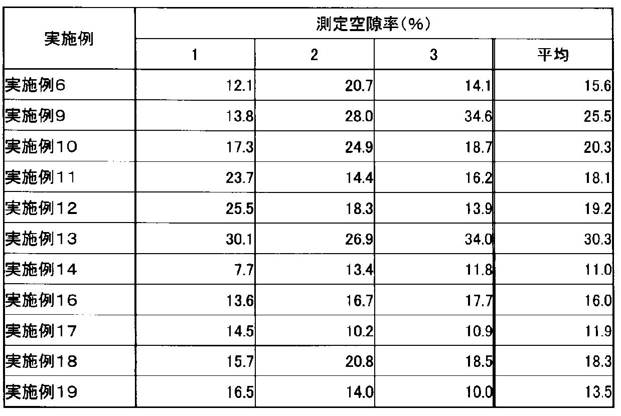
(比較例1)
調製例S4で得られた繊維状の混合カルボン酸銀(平均短軸長さ:120nm、平均長軸長さ:1.706μm、アスペクト比の平均値:16.03)を含有するエタノール分散液0.1mlにヒドラジン一水和物(N2H4・H2O、和光純薬工業(株)製)0.0001mgを添加し、40℃に加熱して前記繊維状の混合カルボン酸銀を液相還元した。その後、溶媒を除去して粉末を回収し、十分に乾燥させた。得られた粉末のSEM写真を図37に示す。
調製例S4で得られた繊維状の混合カルボン酸銀(平均短軸長さ:120nm、平均長軸長さ:1.706μm、アスペクト比の平均値:16.03)を含有するエタノール分散液0.1mlにヒドラジン一水和物(N2H4・H2O、和光純薬工業(株)製)0.0001mgを添加し、40℃に加熱して前記繊維状の混合カルボン酸銀を液相還元した。その後、溶媒を除去して粉末を回収し、十分に乾燥させた。得られた粉末のSEM写真を図37に示す。
(比較例2)
実施例6と同様にしてガラス基板上に前記繊維状の混合カルボン酸銀からなる膜を形成した。このガラス基板を80℃に設定したホットプレート上に置き、1.0質量%のヒドラジン一水和物(N2H4・H2O、和光純薬工業(株)製)を含有するアセトン溶液を前記繊維状の混合カルボン酸銀からなる膜に滴下して3分間加熱し、前記繊維状の混合カルボン酸銀を還元した。その後、膜を十分に乾燥させ、粉末として回収した。この粉末のSEM写真を図38に示す。
実施例6と同様にしてガラス基板上に前記繊維状の混合カルボン酸銀からなる膜を形成した。このガラス基板を80℃に設定したホットプレート上に置き、1.0質量%のヒドラジン一水和物(N2H4・H2O、和光純薬工業(株)製)を含有するアセトン溶液を前記繊維状の混合カルボン酸銀からなる膜に滴下して3分間加熱し、前記繊維状の混合カルボン酸銀を還元した。その後、膜を十分に乾燥させ、粉末として回収した。この粉末のSEM写真を図38に示す。
(比較例3)
実施例6と同様にしてガラス基板上に前記繊維状の混合カルボン酸銀からなる膜を形成した。このガラス基板を285℃まで加熱して前記繊維状の混合カルボン酸銀を熱還元した。その後、膜を十分に乾燥させ、粉末として回収した。この粉末のSEM写真を図39に示す。
実施例6と同様にしてガラス基板上に前記繊維状の混合カルボン酸銀からなる膜を形成した。このガラス基板を285℃まで加熱して前記繊維状の混合カルボン酸銀を熱還元した。その後、膜を十分に乾燥させ、粉末として回収した。この粉末のSEM写真を図39に示す。
図37のSEM写真から明らかなように、前記混合カルボン酸銀を液相還元した場合(比較例1)には、マイクロメートルオーダーの銀ナノ粒子の凝集体が生成し、還元処理前の混合カルボン酸銀の形状が失われることがわかった。また、図38のSEM写真から明らかなように、前記混合カルボン酸銀を滴下還元した場合(比較例2)にも、銀ナノ粒子の凝集体が生成し、還元処理前の混合カルボン酸銀の形状が失われることがわかった。さらに、図39のSEM写真から明らかなように、前記混合カルボン酸銀を熱還元した場合(比較例3)にも、銀ナノ粒子の凝集体が生成し、還元処理前の混合カルボン酸銀の形状(針状)が失われることがわかった。
(実施例20)
実施例6と同様にして銀ワイヤーからなる膜(厚さ:5μm)を作製した。膜の写真を図40に示す。また、膜の電気抵抗率及び光透過率を測定した。電気抵抗率と波長550nmにおける光透過率との関係を図41に示す。
実施例6と同様にして銀ワイヤーからなる膜(厚さ:5μm)を作製した。膜の写真を図40に示す。また、膜の電気抵抗率及び光透過率を測定した。電気抵抗率と波長550nmにおける光透過率との関係を図41に示す。
図40の写真から、電気抵抗率が減少するにつれて膜の透明性が低下することがわかった。また、図41に示した結果から、膜の電気抵抗率と光透過性との間に相関関係があることがわかった。
(実施例21~22)
加熱時間(還元時間)を180秒間(実施例21)及び300秒間(実施例22)に変更した以外は実施例6と同様にして銀ワイヤーからなる膜を作製した。得られた膜の写真を実施例6で得られた膜とあわせて図42に示す。図42の結果から、還元条件によっても膜の光透過性を調整することが可能であることがわかった。
加熱時間(還元時間)を180秒間(実施例21)及び300秒間(実施例22)に変更した以外は実施例6と同様にして銀ワイヤーからなる膜を作製した。得られた膜の写真を実施例6で得られた膜とあわせて図42に示す。図42の結果から、還元条件によっても膜の光透過性を調整することが可能であることがわかった。
(実施例23)
調製例S4で得られた繊維状の混合カルボン酸銀(平均短軸長さ:120nm、平均長軸長さ:1.706μm、アスペクト比の平均値:16.3)を含有するエタノール分散液0.1mlを、80℃に加熱したポリカーボネート基板(タキロン株式会社製「PCSMPS610」、2.6cm×2.6cm、厚さ500μm)上に塗布し、80℃で乾燥によりエタノールを除去した。その後、加熱温度(還元温度)を100℃にしたこと以外は実施例1と同様にして、この繊維状の混合カルボン酸銀にヒドラジンを用いて固気還元処理を施し、銀ワイヤーとポリカーボネート基板とを備える複合体を得た。この複合体の銀ワイヤーが配置された表面のSEM写真を図43A、図43B及び図43Cに示す。
調製例S4で得られた繊維状の混合カルボン酸銀(平均短軸長さ:120nm、平均長軸長さ:1.706μm、アスペクト比の平均値:16.3)を含有するエタノール分散液0.1mlを、80℃に加熱したポリカーボネート基板(タキロン株式会社製「PCSMPS610」、2.6cm×2.6cm、厚さ500μm)上に塗布し、80℃で乾燥によりエタノールを除去した。その後、加熱温度(還元温度)を100℃にしたこと以外は実施例1と同様にして、この繊維状の混合カルボン酸銀にヒドラジンを用いて固気還元処理を施し、銀ワイヤーとポリカーボネート基板とを備える複合体を得た。この複合体の銀ワイヤーが配置された表面のSEM写真を図43A、図43B及び図43Cに示す。
図43A~43BのSEM写真から、得られた複合体においては基板表面に銀ワイヤーからなる膜が配置されていることが確認された。また、図43CのSEM写真から、基板としてポリカーボネート基板を用いた場合には、ガラス基板表面上に膜を製膜した場合よりも個々のワイヤーの金属粒子がより微細になり、さらに、ワイヤーが基板方向へ拡散されていることが確認された。
(実施例24)
加熱時間(還元時間)を30、60、90、120秒間にしたこと以外は実施例23と同様にして、銀ワイヤーとポリカーボネート基板とを備える複合体をそれぞれ得た。これらの複合体について、電気抵抗率(Rs:resistance[Ω/sec])及び光透過率(T:transmittance[%])を測定し、両者の関係をプロットした。結果を図44に示す。図44の結果から、複合体を透明導電体として用いることができることが確認され、透明導電体の性能、すなわち電気抵抗率と光透過率との良好なバランスは、還元条件によっても調整することが可能であることがわかった。
加熱時間(還元時間)を30、60、90、120秒間にしたこと以外は実施例23と同様にして、銀ワイヤーとポリカーボネート基板とを備える複合体をそれぞれ得た。これらの複合体について、電気抵抗率(Rs:resistance[Ω/sec])及び光透過率(T:transmittance[%])を測定し、両者の関係をプロットした。結果を図44に示す。図44の結果から、複合体を透明導電体として用いることができることが確認され、透明導電体の性能、すなわち電気抵抗率と光透過率との良好なバランスは、還元条件によっても調整することが可能であることがわかった。
また、還元時間が30秒間で得られた複合体では光透過率が高く、ほとんど黒色化が観察されなかったが、還元時間が90秒間で得られた複合体では一部が黒色化しており、還元時間が120秒間で得られた複合体では黒色化の度合いが大きく、比較的光透過率が低いものであった。還元時間が120秒間で得られた複合体の断面のSEM写真を図45に示し、参考として製膜前のポリカーボネート基板の断面のSEM写真を図46に示す。
また、還元時間が90秒間で得られた複合体の、黒色化が観察されなかった部分の表面(塗工液の塗布面、以下同じ)のBSE像、SE像をそれぞれ図47A、図47Bに示し、黒色化が観察された部分の表面のBSE写真、SE写真をそれぞれ図48A、図48Bに示す。さらに、還元時間が30、90、120秒間で得られた複合体表面についてレーザー顕微鏡による観察を行った結果を、それぞれ、図49A・B、図50A・B、図51A・Bに示す(A:表面のレーザー顕微鏡写真、B:断面図)。なお、図50は、黒色化が観察されなかった部分と、黒色化が観察された部分との境界部について観察をおこなったものである。
図45~46のSEM写真から、還元時間が120秒間で得られた複合体ではほとんどのワイヤーが基板方向へ拡散され、埋め込まれていることが確認された。また、図45~51Bの結果から、ワイヤーの基板方向への拡散の度合いが大きくなると複合体が黒色化する傾向にあり、また、複合体表面の凹凸が減少する傾向にあることが確認された。
(実施例25)
調製例M1で得られた針状酢酸銀に代えて板状の酢酸銅(I)無水物(和光純薬工業社製、平均短軸長さ:15μm、平均長軸長さ:50μm、アスペクト比の平均値:3.3)を用いたこと以外は実施例1と同様にして製膜した。製膜後、この板状酢酸銅からなる膜を静置した容器内にAr-H2ガス(H2濃度:2.01体積%)を流通させ、500℃で加熱して前記板状酢酸銅を固気還元した。その後、膜を十分に乾燥させ、粉末として回収した。この粉末のX線回折パターンを図52に示す。また、得られた粉末のSEM写真を図53A~53Dに示し、用いた酢酸銅(I)無水物のSEM写真を図54に示す。
調製例M1で得られた針状酢酸銀に代えて板状の酢酸銅(I)無水物(和光純薬工業社製、平均短軸長さ:15μm、平均長軸長さ:50μm、アスペクト比の平均値:3.3)を用いたこと以外は実施例1と同様にして製膜した。製膜後、この板状酢酸銅からなる膜を静置した容器内にAr-H2ガス(H2濃度:2.01体積%)を流通させ、500℃で加熱して前記板状酢酸銅を固気還元した。その後、膜を十分に乾燥させ、粉末として回収した。この粉末のX線回折パターンを図52に示す。また、得られた粉末のSEM写真を図53A~53Dに示し、用いた酢酸銅(I)無水物のSEM写真を図54に示す。
図52~図54の結果から、得られた銅ワイヤーは、還元処理前の酢酸銅の形状を保持しており、また、平均粒子径100nmの銅ナノ粒子が連結した多孔質のものであることが確認された。この銅ワイヤーの平均短軸長さは10μm、平均長軸長さは35μm、アスペクト比の平均値は3.5であった。
以上説明したように、本発明によれば、保護剤やテンプレート等の添加剤を使用しなくても、比較的簡便に多孔質の金属ナノワイヤーや金属マイクロワイヤーを製造することが可能となる。
したがって、本発明の多孔質金属ワイヤーは、透明導電膜の材料として使用する場合にも、保護剤やテンプレート等の添加剤を除去する必要がなく、また、高いアスペクト比を有するものであるため、ITOに代わる透明導電膜の材料などとして有用である。
したがって、本発明の多孔質金属ワイヤーは、透明導電膜の材料として使用する場合にも、保護剤やテンプレート等の添加剤を除去する必要がなく、また、高いアスペクト比を有するものであるため、ITOに代わる透明導電膜の材料などとして有用である。
Claims (19)
- 繊維状の有機金属塩を還元することにより、金属ナノ粒子が連結している多孔質金属ワイヤーを形成させる工程を含み、
前記還元が、プラズマ還元、光還元、レーザー照射還元、及び、前記繊維状の有機金属塩と気体状の還元剤とを接触させる固気還元からなる群から選択されるいずれか一種である多孔質金属ワイヤーの製造方法。 - 前記還元が固気還元であり、前記還元剤が、ヒドラジン、水素化ホウ素ナトリウム、ジボラン及び水素からなる群から選択される少なくとも1種である請求項1に記載の多孔質金属ワイヤーの製造方法。
- 前記還元がプラズマ還元であり、前記プラズマ還元が、Ar、He、N2からなる群から選択される少なくとも1種のガスにマイクロ波を照射して発生させたプラズマによる還元である請求項1に記載の多孔質金属ワイヤーの製造方法。
- 前記繊維状の有機金属塩がカルボン酸金属塩である請求項1~3のうちのいずれか一項に記載の多孔質金属ワイヤーの製造方法。
- 前記カルボン酸金属塩が、酢酸金属塩、プロピオン酸金属塩、酪酸金属塩、吉草酸金属塩及びヘキサン酸金属塩からなる群から選択される少なくとも1種である請求項4に記載の多孔質金属ワイヤーの製造方法。
- 金属化合物及び有機酸を含有する溶液に大気中で超音波を照射して前記繊維状の有機金属塩を形成する工程を更に含む請求項1~5のうちのいずれか一項に記載の多孔質金属ワイヤーの製造方法。
- 金属化合物及び有機酸を含有する溶液に大気中で超音波を照射して有機金属塩からなる核を形成する工程と、前記有機金属塩からなる核を含有する分散液にマイクロ波を照射して前記核を異方粒成長させることにより前記繊維状の有機金属塩を形成する工程とを更に含む請求項1~5のうちのいずれか一項に記載の多孔質金属ワイヤーの製造方法。
- 前記金属化合物が金属酸化物である請求項6又は7に記載の多孔質金属ワイヤーの製造方法。
- 金属ナノ粒子が連結してなる多孔質金属ワイヤー。
- 前記多孔質金属ワイヤーについて、走査型電子顕微鏡によって前記多孔質金属ワイヤーの平均短軸長さを短辺、前記平均短軸長さの2倍の長さを長辺とする微小分析範囲における空隙の投影面積の割合を測定して得られる空隙率の平均が1~50%である請求項9に記載の多孔質金属ワイヤー。
- 前記金属ナノ粒子の平均粒子径が10~100nmである請求項9又は10に記載の多孔質金属ワイヤー。
- アスペクト比(長軸長さ/短軸長さ)の平均値が8~25である請求項9~11のうちのいずれか一項に記載の多孔質金属ワイヤー。
- 請求項9~12のうちのいずれか一項に記載の多孔質金属ワイヤーを含有する膜。
- 前記多孔質金属ワイヤー同士が金属結合している請求項13に記載の膜。
- ポリカーボネートを含有する基板と請求項9~12のうちのいずれか一項に記載の多孔質金属ワイヤーとを備える複合体。
- 繊維状の有機金属塩及び溶媒を含有する塗工液を基板上に塗布する工程と、前記溶媒を除去する工程と、前記繊維状の有機金属塩を還元することにより、金属ナノ粒子が連結している多孔質金属ワイヤーを含有する膜を形成させる工程とを含み、
前記還元が、プラズマ還元、光還元、レーザー照射還元、及び、前記繊維状の有機金属塩と気体状の還元剤とを接触させる固気還元からなる群から選択されるいずれか一種である多孔質金属ワイヤーを含有する膜の製造方法。 - 繊維状の有機金属塩及び溶媒を含有する塗工液をポリカーボネートを含有する基板上に塗布する工程と、前記溶媒を除去する工程と、前記繊維状の有機金属塩を還元することにより、金属ナノ粒子が連結している多孔質金属ワイヤーを形成させ、前記基板と前記多孔質金属ワイヤーとを備える複合体を得る工程とを含み、前記還元が前記繊維状の有機金属塩とヒドラジンとを接触させる固気還元である、複合体の製造方法。
- 金属化合物及び有機酸を含有する溶液に大気中で超音波を照射して繊維状の有機金属塩を形成する繊維状の有機金属塩の製造方法。
- 金属化合物及び有機酸を含有する溶液に大気中で超音波を照射して有機金属塩からなる核を形成し、前記有機金属塩からなる核を含有する分散液にマイクロ波を照射して前記核を異方粒成長させることにより繊維状の有機金属塩を形成する繊維状の有機金属塩の製造方法。
Priority Applications (1)
| Application Number | Priority Date | Filing Date | Title |
|---|---|---|---|
| JP2015534255A JP6730700B2 (ja) | 2013-08-30 | 2014-08-27 | 多孔質金属ワイヤー、それを含有する膜、及びそれらの製造方法 |
Applications Claiming Priority (4)
| Application Number | Priority Date | Filing Date | Title |
|---|---|---|---|
| JP2013-180592 | 2013-08-30 | ||
| JP2013180592 | 2013-08-30 | ||
| JP2014037379 | 2014-02-27 | ||
| JP2014-037379 | 2014-02-27 |
Publications (1)
| Publication Number | Publication Date |
|---|---|
| WO2015030045A1 true WO2015030045A1 (ja) | 2015-03-05 |
Family
ID=52586597
Family Applications (1)
| Application Number | Title | Priority Date | Filing Date |
|---|---|---|---|
| PCT/JP2014/072409 Ceased WO2015030045A1 (ja) | 2013-08-30 | 2014-08-27 | 多孔質金属ワイヤー、それを含有する膜、及びそれらの製造方法 |
Country Status (3)
| Country | Link |
|---|---|
| JP (1) | JP6730700B2 (ja) |
| TW (1) | TW201522732A (ja) |
| WO (1) | WO2015030045A1 (ja) |
Cited By (1)
| Publication number | Priority date | Publication date | Assignee | Title |
|---|---|---|---|---|
| JP2024065412A (ja) * | 2022-10-31 | 2024-05-15 | 日東電工株式会社 | 透明導電性フィルム |
Citations (9)
| Publication number | Priority date | Publication date | Assignee | Title |
|---|---|---|---|---|
| JPS5061366A (ja) * | 1973-09-28 | 1975-05-26 | ||
| JPS5316347A (en) * | 1976-07-30 | 1978-02-15 | Sumitomo Electric Industries | Metal powder manufacturing by hydrogen reduction |
| JPS5919165B2 (ja) * | 1980-05-30 | 1984-05-02 | 日立マクセル株式会社 | 金属磁性粉末の製造方法 |
| JPS59143004A (ja) * | 1983-02-04 | 1984-08-16 | Nissan Chem Ind Ltd | 磁性合金粉末の製造方法 |
| JPH03150302A (ja) * | 1989-11-02 | 1991-06-26 | Sumitomo Metal Mining Co Ltd | 繊維状銅粉及びその製造方法 |
| JP2000302445A (ja) * | 1999-04-19 | 2000-10-31 | Toda Kogyo Corp | 紡錘状ゲータイト粒子粉末、紡錘状ヘマタイト粒子粉末、及び鉄を主成分とする紡錘状金属磁性粒子粉末、並びにそれらの製造法 |
| JP2008208110A (ja) * | 2007-01-31 | 2008-09-11 | Nissan Motor Co Ltd | 多孔性金属錯体、多孔性金属錯体の製造方法、吸着材、分離材、ガス吸着材及び水素吸着材 |
| JP2009525973A (ja) * | 2006-02-07 | 2009-07-16 | 財団法人韓国化學研究院 | 多孔性有無機混成体の製造方法 |
| JP2009529422A (ja) * | 2006-03-10 | 2009-08-20 | 財団法人韓国化學研究院 | 水分の吸着及び脱着のための吸着剤 |
Family Cites Families (1)
| Publication number | Priority date | Publication date | Assignee | Title |
|---|---|---|---|---|
| JPS6188505A (ja) * | 1984-10-08 | 1986-05-06 | Mitsui Toatsu Chem Inc | 強磁性鉄粉の製造方法 |
-
2014
- 2014-08-27 WO PCT/JP2014/072409 patent/WO2015030045A1/ja not_active Ceased
- 2014-08-27 JP JP2015534255A patent/JP6730700B2/ja active Active
- 2014-08-29 TW TW103129897A patent/TW201522732A/zh unknown
Patent Citations (9)
| Publication number | Priority date | Publication date | Assignee | Title |
|---|---|---|---|---|
| JPS5061366A (ja) * | 1973-09-28 | 1975-05-26 | ||
| JPS5316347A (en) * | 1976-07-30 | 1978-02-15 | Sumitomo Electric Industries | Metal powder manufacturing by hydrogen reduction |
| JPS5919165B2 (ja) * | 1980-05-30 | 1984-05-02 | 日立マクセル株式会社 | 金属磁性粉末の製造方法 |
| JPS59143004A (ja) * | 1983-02-04 | 1984-08-16 | Nissan Chem Ind Ltd | 磁性合金粉末の製造方法 |
| JPH03150302A (ja) * | 1989-11-02 | 1991-06-26 | Sumitomo Metal Mining Co Ltd | 繊維状銅粉及びその製造方法 |
| JP2000302445A (ja) * | 1999-04-19 | 2000-10-31 | Toda Kogyo Corp | 紡錘状ゲータイト粒子粉末、紡錘状ヘマタイト粒子粉末、及び鉄を主成分とする紡錘状金属磁性粒子粉末、並びにそれらの製造法 |
| JP2009525973A (ja) * | 2006-02-07 | 2009-07-16 | 財団法人韓国化學研究院 | 多孔性有無機混成体の製造方法 |
| JP2009529422A (ja) * | 2006-03-10 | 2009-08-20 | 財団法人韓国化學研究院 | 水分の吸着及び脱着のための吸着剤 |
| JP2008208110A (ja) * | 2007-01-31 | 2008-09-11 | Nissan Motor Co Ltd | 多孔性金属錯体、多孔性金属錯体の製造方法、吸着材、分離材、ガス吸着材及び水素吸着材 |
Cited By (1)
| Publication number | Priority date | Publication date | Assignee | Title |
|---|---|---|---|---|
| JP2024065412A (ja) * | 2022-10-31 | 2024-05-15 | 日東電工株式会社 | 透明導電性フィルム |
Also Published As
| Publication number | Publication date |
|---|---|
| JPWO2015030045A1 (ja) | 2017-03-02 |
| JP6730700B2 (ja) | 2020-07-29 |
| TW201522732A (zh) | 2015-06-16 |
Similar Documents
| Publication | Publication Date | Title |
|---|---|---|
| JP6616287B2 (ja) | 強磁性金属ナノワイヤー分散液およびその製造方法 | |
| US10400119B2 (en) | Method and apparatus for aerosol-based three-dimensional (3D) printing of flexible graphene electronic devices | |
| CN108698849B (zh) | 通过在悬浮的非负载型石墨烯纳米片上生长氧化锌纳米棒或微米棒获得的石墨烯基复合纳米结构的生产 | |
| TW201708102A (zh) | 碳奈米管分散液及導電性薄膜之製造方法 | |
| CN103460304A (zh) | 透明导电膜、带有透明导电膜的基材及其制备方法 | |
| KR102486556B1 (ko) | 레이저 유도 탄소물질을 기반으로 하는 전극의 제조방법 | |
| CN103590089A (zh) | 一种石墨烯/银复合材料的制备方法 | |
| CN103262173A (zh) | 导电膏和使用了该导电膏的带有导电膜的基材、以及带有导电膜的基材的制造方法 | |
| Liang et al. | Polymer-assisted self-assembly of silver nanoparticles into interconnected morphology and enhanced surface electric conductivity | |
| KR101540030B1 (ko) | Ag가 코팅된 그래핀나노플레이트 및 이의 제조방법 | |
| JP7208803B2 (ja) | 導電性パターン領域付構造体及びその製造方法 | |
| Casa et al. | Conductive adhesive based on mussel-inspired graphene decoration with silver nanoparticles | |
| Tetsumoto et al. | Mechanistic studies on the formation of silver nanowires by a hydrothermal method | |
| Kim et al. | Effects of copper metal organic decomposition ink on properties of single-walled carbon nanotube based flexible transparent electrodes | |
| JP6730700B2 (ja) | 多孔質金属ワイヤー、それを含有する膜、及びそれらの製造方法 | |
| JP2019178059A (ja) | 分散体の製造方法 | |
| JP2017130393A (ja) | 導電性ペーストおよび銀膜の形成方法 | |
| Sugawara et al. | Facile synthesis of silver‐nanobeadwire transparent conductive film by organic‐precursor paint reduction | |
| JP2019160689A (ja) | 分散体、塗膜を含む製品、導電性パターン付き構造体の製造方法、及び、導電性パターン付き構造体 | |
| JP6274076B2 (ja) | 銅粉及びそれを用いた銅ペースト、導電性塗料、導電性シート | |
| CN1817894A (zh) | 碳-金属复合材料及其制备方法 | |
| TW200938486A (en) | Copper hydride nanoparticle, process for producing the same, metallic paste, and article | |
| JP5268520B2 (ja) | 酸化亜鉛微粒子付着樹脂粒子及びその製造方法、並びに導電性粒子及びその製造方法 | |
| JP2012174375A (ja) | 導電性塗膜の製造方法及び導電性塗膜 | |
| Jackson et al. | Photonic sintering of inkjet printable molecular base copper ink at ambient conditions |
Legal Events
| Date | Code | Title | Description |
|---|---|---|---|
| 121 | Ep: the epo has been informed by wipo that ep was designated in this application |
Ref document number: 14840074 Country of ref document: EP Kind code of ref document: A1 |
|
| DPE1 | Request for preliminary examination filed after expiration of 19th month from priority date (pct application filed from 20040101) | ||
| ENP | Entry into the national phase |
Ref document number: 2015534255 Country of ref document: JP Kind code of ref document: A |
|
| NENP | Non-entry into the national phase |
Ref country code: DE |
|
| 122 | Ep: pct application non-entry in european phase |
Ref document number: 14840074 Country of ref document: EP Kind code of ref document: A1 |