WO2015029934A1 - カメラ校正装置、カメラ校正システム、及びカメラ校正方法 - Google Patents
カメラ校正装置、カメラ校正システム、及びカメラ校正方法 Download PDFInfo
- Publication number
- WO2015029934A1 WO2015029934A1 PCT/JP2014/072119 JP2014072119W WO2015029934A1 WO 2015029934 A1 WO2015029934 A1 WO 2015029934A1 JP 2014072119 W JP2014072119 W JP 2014072119W WO 2015029934 A1 WO2015029934 A1 WO 2015029934A1
- Authority
- WO
- WIPO (PCT)
- Prior art keywords
- camera
- calibration
- image
- cameras
- projection matrix
- Prior art date
- Legal status (The legal status is an assumption and is not a legal conclusion. Google has not performed a legal analysis and makes no representation as to the accuracy of the status listed.)
- Ceased
Links
Images



Classifications
-
- G—PHYSICS
- G06—COMPUTING OR CALCULATING; COUNTING
- G06T—IMAGE DATA PROCESSING OR GENERATION, IN GENERAL
- G06T7/00—Image analysis
- G06T7/80—Analysis of captured images to determine intrinsic or extrinsic camera parameters, i.e. camera calibration
-
- G—PHYSICS
- G06—COMPUTING OR CALCULATING; COUNTING
- G06T—IMAGE DATA PROCESSING OR GENERATION, IN GENERAL
- G06T3/00—Geometric image transformations in the plane of the image
- G06T3/20—Linear translation of whole images or parts thereof, e.g. panning
-
- G—PHYSICS
- G06—COMPUTING OR CALCULATING; COUNTING
- G06T—IMAGE DATA PROCESSING OR GENERATION, IN GENERAL
- G06T3/00—Geometric image transformations in the plane of the image
- G06T3/60—Rotation of whole images or parts thereof
-
- G—PHYSICS
- G06—COMPUTING OR CALCULATING; COUNTING
- G06T—IMAGE DATA PROCESSING OR GENERATION, IN GENERAL
- G06T5/00—Image enhancement or restoration
- G06T5/80—Geometric correction
-
- G—PHYSICS
- G06—COMPUTING OR CALCULATING; COUNTING
- G06T—IMAGE DATA PROCESSING OR GENERATION, IN GENERAL
- G06T7/00—Image analysis
- G06T7/60—Analysis of geometric attributes
-
- G—PHYSICS
- G06—COMPUTING OR CALCULATING; COUNTING
- G06V—IMAGE OR VIDEO RECOGNITION OR UNDERSTANDING
- G06V20/00—Scenes; Scene-specific elements
- G06V20/50—Context or environment of the image
- G06V20/56—Context or environment of the image exterior to a vehicle by using sensors mounted on the vehicle
-
- H—ELECTRICITY
- H04—ELECTRIC COMMUNICATION TECHNIQUE
- H04N—PICTORIAL COMMUNICATION, e.g. TELEVISION
- H04N17/00—Diagnosis, testing or measuring for television systems or their details
- H04N17/002—Diagnosis, testing or measuring for television systems or their details for television cameras
-
- H—ELECTRICITY
- H04—ELECTRIC COMMUNICATION TECHNIQUE
- H04N—PICTORIAL COMMUNICATION, e.g. TELEVISION
- H04N23/00—Cameras or camera modules comprising electronic image sensors; Control thereof
- H04N23/90—Arrangement of cameras or camera modules, e.g. multiple cameras in TV studios or sports stadiums
-
- B—PERFORMING OPERATIONS; TRANSPORTING
- B60—VEHICLES IN GENERAL
- B60R—VEHICLES, VEHICLE FITTINGS, OR VEHICLE PARTS, NOT OTHERWISE PROVIDED FOR
- B60R2300/00—Details of viewing arrangements using cameras and displays, specially adapted for use in a vehicle
- B60R2300/40—Details of viewing arrangements using cameras and displays, specially adapted for use in a vehicle characterised by the details of the power supply or the coupling to vehicle components
- B60R2300/402—Image calibration
-
- G—PHYSICS
- G06—COMPUTING OR CALCULATING; COUNTING
- G06T—IMAGE DATA PROCESSING OR GENERATION, IN GENERAL
- G06T2207/00—Indexing scheme for image analysis or image enhancement
- G06T2207/30—Subject of image; Context of image processing
- G06T2207/30168—Image quality inspection
-
- G—PHYSICS
- G06—COMPUTING OR CALCULATING; COUNTING
- G06T—IMAGE DATA PROCESSING OR GENERATION, IN GENERAL
- G06T2207/00—Indexing scheme for image analysis or image enhancement
- G06T2207/30—Subject of image; Context of image processing
- G06T2207/30244—Camera pose
-
- G—PHYSICS
- G06—COMPUTING OR CALCULATING; COUNTING
- G06T—IMAGE DATA PROCESSING OR GENERATION, IN GENERAL
- G06T2207/00—Indexing scheme for image analysis or image enhancement
- G06T2207/30—Subject of image; Context of image processing
- G06T2207/30248—Vehicle exterior or interior
- G06T2207/30252—Vehicle exterior; Vicinity of vehicle
Definitions
- the present invention relates to a camera calibration device, a camera calibration system, and a camera calibration method.
- an image behind the vehicle taken by the in-vehicle camera is displayed on the in-vehicle monitor, and a situation in the vicinity of the rear of the vehicle that becomes a blind spot from the driver is displayed on the in-vehicle monitor.
- Devices that are visually recognized as images are known.
- a calibration index is installed at the rear of the vehicle, while looking at the image of the calibration index reflected on the in-vehicle monitor, The mounting state of the in-vehicle camera is adjusted so that the image of the calibration index is appropriately displayed on the in-vehicle monitor. Moreover, the image displayed on a vehicle-mounted monitor is calibrated appropriately by performing the predetermined calculation process based on the image of the parameter
- the calibration index is precisely set for the vehicle. It is necessary to install the vehicle or to precisely install the calibration index after setting the calibration index at a predetermined position. Therefore, for example, in a vehicle production line, it has been necessary to modify the equipment at a large cost in order to improve the alignment accuracy between the vehicle and the calibration index.
- Patent Document 1 discloses a camera calibration apparatus that contributes to simplifying the calibration environment.
- parameter deriving means for obtaining parameters for projecting and synthesizing each captured image from N cameras on a predetermined plane is arranged in each common imaging region.
- the parameter is obtained based on the result of photographing the calibration pattern by each camera, and the calibration patterns are arranged independently of each other.
- the present invention has been made in view of the above-described problems, and the object of the present invention is to greatly reduce the burden on the operator associated with the transportation or installation of the calibration pattern during calibration work, and to store the calibration pattern. It is an object of the present invention to provide a camera calibration apparatus, a camera calibration system, and a camera calibration method that can significantly reduce the size of a place.
- a camera calibration device is a camera calibration device that calibrates images captured by a plurality of cameras having a common imaging region in which at least two calibration patterns are arranged.
- An image conversion unit that converts an image captured by each camera based on a projection matrix that is converted into an overhead view based on an initial parameter of each camera and generates a converted image; and the plurality of cameras among the converted images
- An error evaluator that calculates an error between a converted image by a reference camera selected from the above and a converted image by a camera other than the reference camera, and a projection matrix so that the images in the common imaging area of each camera match based on the error
- a projection matrix updating unit for updating the camera parameters, and camera parameters including external parameters related to the posture of each camera with respect to the ground based on the updated projection matrix.
- a camera parameter calculation unit configured to output, characterized in that it comprises.
- the camera calibration system is captured by the plurality of cameras using the camera calibration apparatus, a plurality of cameras having a common imaging region, and camera parameters of each camera obtained from the camera calibration apparatus.
- a composite image generation device that calibrates images to generate a composite image and a display device that displays the composite image are provided.
- the camera calibration method is a camera calibration method for calibrating images captured by a plurality of cameras having a common imaging region in which at least two calibration patterns are arranged, and includes initial parameters of each camera. Based on a projection matrix that converts to a bird's-eye view based on the image, the image captured by each camera is converted to generate a converted image, and among the converted images, a converted image by a reference camera selected from the plurality of cameras and the converted image Calculate the error with the converted image by the camera other than the reference camera, update the projection matrix so that the images of the common imaging area of each camera match based on the error, and update the projection matrix of each camera based on the updated projection matrix Camera parameters including external parameters related to the posture with respect to the ground are calculated.
- the present invention at the time of camera image calibration, it is not necessary to use an arrangement relationship of feature points such as calibration patterns in a common imaging region, and the number and dimensions of the calibration patterns can be suppressed to the minimum necessary.
- the storage location for the calibration pattern used for the calibration work can be significantly reduced.
- FIG. 1 is an overall configuration diagram showing an overall configuration of an embodiment of a camera calibration system according to the present invention.
- the top view which shows typically the installation position and imaging region of each camera. It is a figure explaining the calibration calculation process of the camera by the camera calibration apparatus shown in FIG. 1, Comprising: The top view which shows typically the vehicle arrange
- FIG. 2 is a basic configuration diagram showing a basic configuration of the camera calibration apparatus shown in FIG. 1. The flowchart explaining the camera calibration method by the camera calibration system shown in FIG.
- a camera calibration device and a camera calibration system will be described with reference to the drawings.
- the camera calibration device and the camera calibration system of the present embodiment are other than the vehicle.
- the present invention can also be applied when calibrating images taken by a plurality of cameras attached to a thing.
- a case where four cameras are used and two adjacent cameras have a common imaging area will be described.
- the number of cameras in the entire system and the number of cameras imaging the common imaging area are as follows. It can be changed as appropriate according to the user's request.
- calibration can be performed using a feature object existing in a common imaging region without using a calibration target.
- FIG. 1 shows the overall configuration of an embodiment of a camera calibration system according to the present invention.
- the illustrated camera calibration system 100 mainly includes an imaging device 101 having four cameras 111 to 114, a camera interface 102, an image storage device (RAM) 104, a parameter storage device (ROM) 105, and an input device.
- 106 an arithmetic device 103 having a camera calibration device 108 and a composite image generation device 109, and a display device 107.
- the cameras 111 to 114 constituting the imaging apparatus 101 are installed, for example, on the front, rear, left and right sides of the vehicle 1, and the four cameras 111 to 114 surround the vehicle 1 including the calibration target R. Images are captured.
- the calibration target R has information necessary for camera calibration such as a calibration pattern (see FIG. 3) which is a calibration index described later, and each of the cameras 111 to 114 is calibrated at the time of camera image calibration.
- the target R is imaged, and the captured image is transmitted to the arithmetic device 103 via the camera interface 102.
- the dotted lines in FIG. 2 represent the imaging areas of the cameras 111 to 114, and in order to calibrate the camera image precisely, adjacent cameras are overlapped, that is, areas that are photographed in common to both cameras.
- common imaging region RK1 to RK4.
- the arithmetic unit 103 uses the camera calibration unit 108 to calculate camera parameters for calibrating the images captured by the cameras 111 to 114.
- the camera parameters are transmitted to the composite image generation device 109.
- images captured by the cameras 111 to 114 are transmitted to the computing device 103 via the camera interface 102, and are converted into viewpoints and synthesized by the composite image generating device 109 of the computing device 103 using the camera parameters.
- 107 and is presented to the user or the like via the display device 107 as an image (overhead image) of the vehicle 1 looking down from directly above.
- the images obtained from the cameras 111 to 114 are viewpoint-converted and combined to generate an overhead image around the vehicle 1, so that each of the cameras 111 to 114 is, for example, a fish It is desirable to use an eye camera or the like that can shoot at a wide angle.
- the camera interface 102 appropriately samples the image signals transmitted from the cameras 111 to 114 and transmits them to the arithmetic device 103.
- the image storage device (RAM) 104 stores images taken by the cameras 111 to 114 and various calculation results calculated by the calculation device 103.
- the parameter storage device (ROM) 105 includes, for example, design values related to the installation positions and orientations (installation angles) of the cameras 111 to 114 (these are referred to as external parameters), focal lengths of the cameras 111 to 114, and pixels.
- Preliminary information (camera parameter initial values) necessary for camera image calibration of camera parameters such as size, optical axis center, design values related to the distortion function, etc. (these are called internal parameters) is written and stored.
- the input device 106 receives input information such as information necessary for camera calibration based on the operation of the user or the like, and transmits the input information to the arithmetic device 103.
- the arithmetic device 103 cooperates with the camera interface 102, the image storage device (RAM) 104, the parameter storage device (ROM) 105, the input device 106, the display device 107, and the like, and includes various operations including the above-described calculation at the time of camera image calibration. Perform the operation. Specifically, the arithmetic device 103 stores the image signal transmitted from the camera interface 102 in the image storage device 104, or stores the camera parameter initial value stored in the parameter storage device 105 or the image storage device 104. The image is read and the viewpoint is converted and synthesized (synthesized image generation device 109), and the display device 107 is displayed on the display device 107 after the viewpoint is converted and synthesized.
- a calibration calculation for calculating the installation position and installation posture of the camera is performed so that the overhead view image generated by the viewpoint conversion / synthesis is an image looking down from the vehicle 1 (camera calibration apparatus 108). Then, the input device 106 performs processing for utilizing the input information received from the user or the like for the calibration calculation.
- the camera image calibration calculation process will be described later.
- the display device 107 displays an image obtained from each of the cameras 111 to 114 based on an instruction transmitted from the arithmetic device 103. For example, the display device 107 displays an image of only the camera 112 facing backward according to an instruction transmitted from the arithmetic device 103 without conversion and presents it to the user or the like, or an image obtained from the cameras 111 to 114 A bird's-eye view image generated by converting and synthesizing viewpoints is displayed.
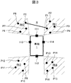
- a vehicle 1 is arranged on a calibration target R used in the camera image calibration calculation processing by the camera calibration device 108, and at least the adjacent imaging areas RK1 to RK1 around the vehicle 1 are arranged.
- Calibration patterns P1 to P16 which are calibration indexes, are arranged on RK4.
- the calibration patterns P1 to P16 are composed of, for example, a plate having a flat disk shape or a polygonal shape such as a square shape, and have a size that can be visually recognized on the images when captured by the cameras 111 to 114. have.
- the calibration patterns P1 to P16 are made of a circular plate, the center portion of the calibration pattern P1 to P16, and if the calibration pattern P1 to P16 is a square plate, the corner portion of the plate is a mark that uniquely defines each calibration pattern. If it has, the shape can be selected appropriately. Further, the calibration patterns in each common imaging region may have the same shape or different shapes.
- each calibration pattern P1 to P4 are installed in the common imaging area RK1 of the camera 111 and the camera 114, and four calibration patterns P5 to P8 are installed in the common imaging area RK2 of the camera 111 and the camera 113.
- the four calibration patterns P9 to P12 are installed in the common imaging area RK3 of the camera 113 and the camera 112, and the four calibration patterns P13 to P16 are installed in the common imaging area RK4 of the camera 112 and the camera 114.
- these calibration patterns can be installed at arbitrary positions in each common imaging region, it is desirable that the interval between the calibration patterns is large.
- the number of calibration patterns arranged in each common imaging region can be appropriately changed according to, for example, calibration accuracy.
- auxiliary calibration indexes used when calibrating camera images.
- a camera image can be calibrated if a texture pattern is drawn on a plane as a background even if a point such as a calibration pattern does not exist.
- the 16 calibration patterns shown in the present embodiment are necessary, and the two The interval between the calibration patterns is measured by an operator or the like and is input to the camera parameter calculation unit 145 in advance via the input device 106.
- the interval between two calibration patterns input by an operator or the like is used to determine the distance corresponding to one pixel.
- the interval between two calibration patterns input by an operator or the like is used to determine the distance corresponding to one pixel.
- calibration can be performed until the image of the overhead view viewpoint is generated, but how much distance the size of one pixel of the video actually corresponds to (how many mm corresponds) In such a case is not allowed.
- the calibration pattern may be installed at an arbitrary position as long as the calibration pattern is captured by any of the four cameras.
- the calibration pattern is not necessarily required for the common imaging region. Therefore, if two calibration patterns are installed in a range photographed by any one of the four cameras, a case where no calibration pattern is installed in the four common imaging regions is allowed.
- an object having a point (that is, a feature point) that can be used for calibration exists in the common imaging region. It is possible to calibrate using such object feature points.
- Such an object may be not only a three-dimensional object but also a planar object such as a pattern or a texture, for example, sand or asphalt.
- the standard deviation of the luminance value in the common imaging region can be used. For example, the calculated standard deviation value is determined in advance.
- the threshold it can be determined that there is an object that can be a feature point that can be used for calibration, and if it is less than the threshold, it can be determined that no object exists. If it is determined that there is no object, a calibration pattern is required, so the operator is notified via the display device 107 that the calibration pattern should be installed.
- the camera image calibration calculation processing by the camera calibration device 108 using the calibration target R described above is performed using a projection matrix related to the ground (plane).
- the ground (plane) is reflected in the images of the two cameras corresponding to a certain common imaging area, and these are the same.
- the imaging target is a plane, it can be converted into the same image (an image viewed from the viewpoint of one camera as viewed from the other viewpoint) by geometric transformation using a projection matrix.
- the projection matrix is a matrix that represents a projection relationship between planes reflected in two camera images corresponding to a certain common imaging region, and this projection matrix is a relative external parameter between the two cameras and a plane in the image. Contains normal vectors.
- singular value decomposition for this projection matrix it is possible to extract the external parameters between the two cameras and the normal vector of the plane.
- the singular value decomposition for the projection matrix is a known technique, and thus detailed description thereof is omitted. If the normal vector of each camera plane is known, the viewpoint of each camera image can be converted to an overhead image obtained by looking down at the vehicle 1 from directly above. If the external parameters between the cameras are known, a common imaging area can be obtained. A synthesized image can be generated by synthesizing the overhead images of the two corresponding cameras without deviation.
- the projection matrix used in the camera image calibration calculation process is calculated based on an iterative method, for example.
- This iterative method is a method in which the current error is obtained and the projection matrix is updated so that the error is reduced.
- the steepest descent method For example, the steepest descent method, the Gauss-Newton method, the Levenberg Markert method, etc.
- a method that does not use differentiation such as a particle filter or a genetic algorithm.
- the steepest descent method repeatedly performs the procedure of differentiating the error function, obtaining the decreasing direction of the error function, and slightly updating the parameters in the decreasing direction until the error reduction stops. It is a method to do.
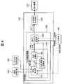
- the camera calibration device 108 includes an image conversion unit 141, an error evaluation unit 142, and a projection matrix update unit 143 in order to estimate camera parameters for generating a bird's-eye view video without deviation.
- the calibration unit 144 calculates a projection matrix between the cameras corresponding to each common imaging region, and the image conversion unit 141 for each of the two images corresponding to each of the four common imaging regions RK1 to RK4.
- the image conversion processing by, the error evaluation processing by the error evaluation unit 142, and the update processing by the projection matrix update unit 143 are performed. That is, the calibration unit 144 includes two images of the camera 111 and the camera 114 corresponding to the common imaging region RK1, two images of the camera 111 and the camera 113 corresponding to the common imaging region RK2, and the camera 112 corresponding to the common imaging region RK3.
- the image conversion unit 141 of the calibration unit 144 receives the images of the cameras 111 to 114 from the image storage unit 104, and mainly uses the projection matrix obtained by the projection matrix update unit 143 to share each of the images.
- the viewpoint conversion of the two images corresponding to the imaging region is performed, and the converted image after the viewpoint conversion is transmitted to the error evaluation unit 142.
- the projection matrix used in this viewpoint conversion for example, when processing is performed on the images of the two cameras 111 and 114 corresponding to the common imaging region RK1, includes the ground (including the calibration patterns P1 to P4 captured by the camera 114). This is a matrix for performing conversion to match the (planar) image with the ground image including the calibration patterns P1 to P4 captured by the camera 111.
- an error is necessarily included between the two images, so even if the projection example is used, the image does not completely match, but the image shown on the camera 114 is the image shown on the camera 111. Close image.
- the design related to the postures of the cameras 111 to 114 stored in advance in the parameter storage unit 105 since the projection matrix cannot be obtained from the projection matrix update unit 143, the design related to the postures of the cameras 111 to 114 stored in advance in the parameter storage unit 105. Based on the value (initial parameter), image conversion is performed by calculating a projection matrix (initial projection matrix) for performing conversion for matching the images of the ground (plane) captured by the two cameras corresponding to the respective common imaging regions. To implement. In the second and subsequent image conversion processes at the time of calibration, viewpoint conversion of the images of the two cameras corresponding to the respective common imaging regions is performed using the projection matrix obtained by the projection matrix update unit 143.
- four calibration patterns are arranged in the respective common imaging areas as feature points of the calibration target.
- the four calibration patterns which are calibration indexes
- the four calibration patterns in the images captured by the two cameras corresponding to the common imaging area are created.
- a projection matrix for converting the coordinate positions of the four calibration patterns in the image of one camera into the coordinate positions of the four calibration patterns in the image of the other camera is uniquely calculated. be able to. That is, when four or more calibration patterns are arranged in each common imaging region, the image conversion unit 141 uses the projection matrix obtained from the simultaneous equations created for such a calibration pattern as an image conversion unit. The image conversion can be performed using the initial projection matrix used in the first image conversion processing according to 141.
- the error evaluation unit 142 evaluates an error with respect to the images of the two cameras corresponding to the respective common imaging regions image-converted by the image conversion unit 141, and the error between the images of the two cameras is transferred to the projection matrix update unit 143.
- Send For example, when processing is performed on the images of the two cameras 111 and 114 corresponding to the common imaging region RK1, the image displayed on the camera 114 is converted by the image conversion unit 141 to match the image displayed on the camera 111.
- the image is converted based on the design value stored in advance in the parameter storage unit 105 in the first image conversion process by the image conversion unit 141, for example, based on the design value based on the actual camera mounting error and the like.
- the error evaluation unit 142 evaluates an error amount between the images of the two cameras.
- the error evaluation unit 142 transmits the projection matrix output from the image conversion unit 141 to the camera parameter calculation unit 145.
- the error evaluation unit 142 for example, the sum of squares of the distances between the corresponding calibration patterns, the sum of squares of the luminance differences of the corresponding pixels, or the distance The sum of the sum of squares and the sum of squares of the luminance difference may be used.
- the difference in the feature amount of the object in the corresponding pixel in the common imaging region is defined as the error amount.
- the feature amount of the object is preferably not affected by the difference in sensitivity between the cameras or the difference in the amount of incident light.
- an edge direction feature amount is used. This edge direction feature quantity represents the local luminance increasing direction in each pixel, and is based on the distribution of the edge direction feature quantity in the image and the statistics (for example, average value) of the edge direction feature quantity for each object.
- the feature object can be discriminated. When a camera that captures a common imaging area captures the same object, ideally the feature values in the corresponding pixels match. Therefore, a projection matrix between images can be obtained by using the degree of coincidence of the feature values as an error function and performing optimization so that the error is minimized.
- the projection matrix update unit 143 uses an iterative method to reduce the error based on the error obtained by the error evaluation unit 142 and the projection matrix before update transmitted from the calibration unit 144 to the camera parameter calculation unit 145.
- the projection matrix is updated, and the updated projection matrix is transmitted to the image conversion unit 141.
- the projection matrix update unit 143 obtains a partial derivative of the error function in the current camera parameter, and updates the projection matrix by slightly updating the camera parameter in the direction opposite to the vector represented by the partial derivative of the error function.
- the calibration unit 144 performs image conversion processing by the image conversion unit 141 and error evaluation by the error evaluation unit 142 for each of the two images of the camera corresponding to each common imaging region when the camera image is calibrated.
- the projection matrix to be converted so that the images of the two cameras corresponding to the common imaging region are equal (the error is zero) is calculated by repeatedly performing the process and the update process by the projection matrix update unit 143, and the calculation result Is transmitted to the camera parameter calculation unit 145.
- the camera parameter calculation unit 145 decomposes the projection matrix corresponding to the four cameras 111 to 114 obtained by the calibration unit 144 using singular value decomposition or the like, and compares the normal vector of the ground (plane) and the relative between the cameras. External parameters are extracted, and camera parameters calculated from the external parameters between the cameras (particularly, external parameters relating to the posture of the camera with respect to the plane (ground)) are transmitted to the composite image generation device 109.
- the external parameters between the cameras are in the form of external parameters of the camera 114 with respect to the camera 111, external parameters of the camera 113 with respect to the camera 111, external parameters of the camera 112 with respect to the camera 114, and external parameters of the camera 112 with respect to the camera 113.
- the camera parameter calculation unit 145 may estimate internal parameters related to the focal length, pixel size, optical axis center, distortion function, and the like of each camera, if necessary.
- the camera parameters output from the camera parameter calculation unit 145 are used when the composite image generation device 109 creates a mapping table for generating an overhead image.
- the mapping table describes the correspondence between each pixel of the synthesized bird's-eye image and the pixel in each image of the cameras 111 to 114, and the final synthesized bird's-eye view is created by mapping the luminance values based on this correspondence. An image can be obtained.
- the images captured by the respective cameras are calibrated using the projection matrix relating to the ground (plane), so that the common imaging region is calibrated at the time of camera image calibration.
- the coordinates of the feature points may be extracted by image recognition, or an image is presented to the user or the like via the display device 107 or the like, and the feature point coordinates on the image are displayed via the input device 106 such as a mouse.
- the user or the like may specify (information input indicated by a dotted line in FIG. 4).
- information obtained by the camera calibration device 108 of the embodiment is the relationship between the camera posture with respect to the plane (ground) of each camera and the relative position and posture between the cameras. Therefore, the relative amount of rotation of the vehicle 1 with respect to the ground (the amount of rotation of the vehicle 1 in the yaw direction) cannot be obtained in principle.
- the relative rotation amount of the vehicle 1 with respect to the ground can be estimated from the direction of the axle of the vehicle 1 using the camera attachment position information.
- the error of the initial installation position of the camera is assumed to be large, it is difficult to estimate the relative rotation amount of the vehicle 1 with respect to the ground from the camera installation position information.
- a mark for recognizing the relationship between the ground and the vehicle 1 is disposed around the vehicle 1 (for example, a bar is disposed in parallel to the vehicle 1), and the relative position of the vehicle 1 to the ground is determined.
- the relative rotation amount of the vehicle 1 with respect to the ground can be estimated.
- an image is presented to the user or the like via the display device 107 or the like, and the user or the like is finely displayed via the input device 106 so that a mark for recognizing the relationship between the ground and the vehicle 1 is in a predetermined manner.
- the amount of rotation may be input while adjusting (information input indicated by a one-dot chain line in FIG. 4). Since the input result is immediately reflected in the image, the user or the like can adjust the relative rotation amount of the vehicle 1 with respect to the ground while checking the image.
- Camera image calibration calculation processing by the camera calibration device 108 (embodiment of the camera calibration device according to the present invention) of the arithmetic device 103 shown in FIG. 1, that is, camera parameter calculation processing of each camera 111 to 114 by the camera calibration device 108
- the calibration calculation process flow includes an image acquisition process S501, an initial projection matrix generation process S502, an image conversion process S503, an error evaluation process S504, a projection matrix update process S505, a convergence determination process S508, and a scale correction process S509.
- the matrix update process S505 includes an update amount calculation process 506 and a projection matrix calculation process 507.
- an image acquisition process S501, an image conversion process S503, an error evaluation process S504, a convergence determination process S508, and a projection matrix update process S505 are performed in this order, and thereafter, an image conversion process S503, an error evaluation process S504, The convergence determination process S508 and the projection matrix update process S505 are repeatedly performed. Note that the error evaluation value is evaluated in the convergence determination process S508, and if it is determined that the error evaluation value has converged, the process stops.
- an image acquisition process S501 is performed, and images taken by each camera are read from the image storage device 104.
- images taken by each camera are read from the image storage device 104.
- four images corresponding to four cameras that photograph the ground including the calibration pattern are input.
- image conversion processing S503 is performed by the image conversion unit 141 shown in FIG. 4 on the image acquired in the video acquisition processing S501.
- This image conversion processing S503 is performed using a projection matrix.
- the projection matrix at the time of the first calibration is calculated by the initial projection matrix generation processing S502.
- initial camera parameters including the camera posture and position are received from the parameter storage device 105, and the initial camera is calculated.
- a projection matrix corresponding to the parameter is calculated.
- the obtained initial projection matrix is used in the first process in the image conversion process S503, and in the subsequent image conversion process S503, the projection matrix output in the projection matrix update process S505 is used.
- an error evaluation process S504 is performed by the error evaluation unit 142 shown in FIG. 4.
- the output of the image conversion process S503 is received, and one of the two camera images corresponding to each common imaging region is received.
- An error amount indicating how much the image of the common imaging region portion of the image of the other common imaging region portion is compared with the image of the other common imaging region portion is calculated and output.
- a convergence determination process S508 is performed by comparing the error amount output in the error evaluation process S504 with a predetermined determination threshold value.
- the convergence determination of the error amount output in the error evaluation process S504 is performed, and when it is determined that the error has not converged, the projection matrix update unit 143 shown in FIG. S505 is performed.
- This projection matrix update process S505 includes an update amount calculation process S506 and a projection matrix calculation process S507.
- an update amount of camera parameters such as camera posture and position is calculated.
- the update amount is a fine correction of the camera parameters such as camera posture and position so that the error amount indicating how much the image of one common imaging area part matches the image of the other common imaging area part is reduced.
- the amount to be. can be calculated, for example, by obtaining a partial differential of the error function in the current camera parameter.
- the update amount calculation process S506 the value after fine correction of the camera parameter is output.
- the projection matrix calculation process S507 the output value of the update amount calculation process S506 is received, and a projection matrix corresponding to the camera parameter is calculated. Output.
- the image conversion process S503, the error evaluation process S504, and the projection matrix update process S505 are repeatedly performed until the output value in the error evaluation process S504 converges.
- the error amount output in the error evaluation process S504 for each execution is evaluated. If the error amount becomes extremely small, it is determined that the error has converged, and the process is terminated.
- the image conversion process S503, the error evaluation process S504, and the projection matrix update process S505 are repeatedly performed, so that the image of one common imaging area portion matches the image of the other common imaging area portion. It is possible to obtain a normal vector of the common imaging area from the images, and the images can be connected without deviation, and the relationship between the camera and the plane can be clarified. Can be realized.
- the scale correction processing S509 is performed to correct this.
- the distance information regarding the interval between the calibration patterns measured by an operator or the like and input via the input device 106 is used to correct the camera parameters and generate a final overhead image.
- the process involves calculating the number of pixels that the calibration pattern interval should appear in the overhead image based on the external parameters of the camera at the overhead viewpoint, and calculating the actual calibration pattern interval in the overhead image.
- the camera parameters are corrected so that the pixel interval is the same.
- the present invention is not limited to the above-described embodiment, and includes various modifications.
- the above-described embodiment has been described in detail for easy understanding of the present invention, and is not necessarily limited to one having all the configurations described.
- a part of the configuration of an embodiment can be replaced with the configuration of another embodiment, and the configuration of another embodiment can be added to the configuration of an embodiment.
- control lines and information lines indicate what is considered necessary for the explanation, and not all the control lines and information lines on the product are necessarily shown. Actually, it may be considered that almost all the components are connected to each other.
Landscapes
- Engineering & Computer Science (AREA)
- Physics & Mathematics (AREA)
- General Physics & Mathematics (AREA)
- Theoretical Computer Science (AREA)
- Multimedia (AREA)
- Computer Vision & Pattern Recognition (AREA)
- Signal Processing (AREA)
- Geometry (AREA)
- Health & Medical Sciences (AREA)
- Biomedical Technology (AREA)
- General Health & Medical Sciences (AREA)
- Closed-Circuit Television Systems (AREA)
- Image Processing (AREA)
- Studio Devices (AREA)
- Image Analysis (AREA)
- Mechanical Engineering (AREA)
Abstract
Description
図1は、本発明に係るカメラ校正システムの実施形態の全体構成を示したものである。図示するカメラ校正システム100は、主に、4台のカメラ111~114を有する撮像装置101と、カメラインターフェース102と、画像記憶装置(RAM)104と、パラメータ記憶装置(ROM)105と、入力装置106と、カメラ校正装置108と合成画像生成装置109を有する演算装置103と、表示装置107と、を備えている。
次に、図1に示す演算装置103のカメラ校正装置108(本発明に係るカメラ校正装置の実施形態)によるカメラ画像の校正演算処理、すなわちカメラ校正装置108による各カメラ111~114のカメラパラメータの演算処理について図3、4を参照して詳述する。
以下、カメラ画像の校正演算処理の一連の流れを図5を参照して説明する。図1に示す演算装置103のカメラ校正装置108(本発明に係るカメラ校正装置の実施形態)によるカメラ画像の校正演算処理、すなわちカメラ校正装置108による各カメラ111~114のカメラパラメータの演算処理について、この校正演算処理フローは、画像取得処理S501、初期射影行列生成処理S502、画像変換処理S503、誤差評価処理S504、射影行列更新処理S505、収束判定処理S508、スケール補正処理S509から構成され、射影行列更新処理S505は、更新量計算処理506と射影行列計算処理507から構成される。初回の校正時は、画像取得処理S501、画像変換処理S503、誤差評価処理S504、収束判定処理S508、射影行列更新処理S505の順で実施され、以降は、画像変換処理S503、誤差評価処理S504、収束判定処理S508、射影行列更新処理S505が繰り返して実施される。なお、収束判定処理S508で誤差評価値を評価し、誤差評価値が収束したと判定されれば当該処理は停止する。
100 カメラ校正システム
101 撮像装置
102 カメラインターフェース
103 演算装置
104 画像記憶装置(RAM)
105 パラメータ記憶装置(ROM)
106 入力装置
107 表示装置
108 カメラ校正装置
109 合成画像生成装置
111~114 カメラ
141 画像変換部
142 誤差評価部
143 射影行列更新部
144 校正部
145 カメラパラメータ算出部
P1~P16 校正パターン
R キャリブレーションターゲット
RK1~RK4 共通撮像領域
S501 映像取得処理
S502 初期射影行列生成処理
S503 画像変換処理
S504 誤差評価処理
S505 射影行列更新処理
S506 更新量計算処理
S507 射影行列計算処理
S508 収束判定処理
S509 スケール補正処理
Claims (6)
- 車両に搭載され、地面を含む車両周囲を撮像し、かつ共通撮像領域を有する複数のカメラを前記共通撮像領域に配置された少なくとも3つの校正パターンによって校正するカメラ校正装置であって、
各カメラで撮像された画像を所定の射影行列に基づいて俯瞰視点の画像に変換する画像変換部と、
前記複数のカメラのうち、所定のカメラで撮像された前記校正パターンの変換画像と該所定のカメラとの間で共通撮像領域を有する他のカメラで撮像された前記校正パターンの変換画像との誤差を算出する誤差評価部と、
前記誤差に基づいて前記所定の射影行列を更新する射影行列更新部と、
前記校正パターンのうちの任意の2つの校正パターンの間の距離情報を入力する距離情報入力部と、
前記誤差評価部で算出される前記誤差がゼロになる射影行列を変換画像中の地面の法線ベクトルとカメラ間の相対的な外部パラメータとに分解し、前記地面の法線ベクトルとカメラ間の相対的な外部パラメータと、前記距離情報入力部から入力された距離情報とから、各カメラの地面に対する姿勢に関する外部パラメータを含むカメラパラメータを算出するカメラパラメータ算出部と、を備えていることを特徴とするカメラ校正装置。 - 前記地面に対する前記車両の相対的な回転量を入力する回転量入力部をさらに備え、
前記カメラパラメータ算出部は、前記回転量入力部から入力された前記回転量を加味して前記カメラパラメータを算出することを特徴とする、請求項1に記載のカメラ校正装置。 - 車両に搭載され、地面を含む車両周囲を撮像し、かつ共通撮像領域を有する複数のカメラを前記共通撮像領域に存在する物体の特徴点を用いて校正するカメラ校正装置であって、
各カメラで撮像された画像を所定の射影行列に基づいて俯瞰視点の画像に変換する画像変換部と、
前記複数のカメラのうち、所定のカメラで撮像された前記物体の変換画像と該所定のカメラとの間で共通撮像領域を有する他のカメラで撮像された前記物体の変換画像との誤差を算出する誤差評価部と、
前記誤差に基づいて前記所定の射影行列を更新する射影行列更新部と、
前記物体のうちの任意の2点の間の距離情報を入力する距離情報入力部と、
前記誤差評価部で算出される前記誤差がゼロになる射影行列を変換画像中の地面の法線ベクトルとカメラ間の相対的な外部パラメータとに分解し、前記地面の法線ベクトルとカメラ間の相対的な外部パラメータと、前記距離情報入力部から入力された距離情報とから、各カメラの地面に対する姿勢に関する外部パラメータを含むカメラパラメータを算出するカメラパラメータ算出部と、を備えていることを特徴とするカメラ校正装置。 - 前記地面に対する前記車両の相対的な回転量を入力する回転量入力部をさらに備え、
前記カメラパラメータ算出部は、前記回転量入力部から入力された前記回転量を加味して前記カメラパラメータを算出することを特徴とする、請求項3に記載のカメラ校正装置。 - 車両に搭載され、地面を含む車両周囲を撮像し、かつ共通撮像領域を有する複数のカメラを前記共通撮像領域に配置された少なくとも3つの校正パターンによって校正するカメラ校正方法であって、
各カメラで撮像された画像を所定の射影行列に基づいて俯瞰視点の画像に変換するステップと、
前記複数のカメラのうち、所定のカメラで撮像された前記校正パターンの変換画像と該所定のカメラとの間で共通撮像領域を有する他のカメラで撮像された前記校正パターンの変換画像との誤差を算出するステップと、
前記誤差に基づいて前記所定の射影行列を更新するステップと、
前記誤差がゼロになる射影行列を変換画像中の地面の法線ベクトルとカメラ間の相対的な外部パラメータとに分解し、前記地面の法線ベクトルとカメラ間の相対的な外部パラメータと、前記校正パターンのうちの任意の2つの校正パターンの間の距離情報とから、各カメラの地面に対する姿勢に関する外部パラメータを含むカメラパラメータを算出するステップと、からなることを特徴とする、カメラ校正方法。 - 車両に搭載され、地面を含む車両周囲を撮像し、かつ共通撮像領域を有する複数のカメラを前記共通撮像領域に存在する特徴物体によって校正するカメラ校正方法であって、
各カメラで撮像された画像を所定の射影行列に基づいて俯瞰視点の画像に変換するステップと、
前記複数のカメラのうち、所定のカメラで撮像された前記特徴物体の変換画像と該所定のカメラとの間で共通撮像領域を有する他のカメラで撮像された前記特徴物体の変換画像との誤差を算出するステップと、
前記誤差に基づいて前記所定の射影行列を更新するステップと、
前記誤差がゼロになる射影行列を変換画像中の地面の法線ベクトルとカメラ間の相対的な外部パラメータとに分解し、前記地面の法線ベクトルとカメラ間の相対的な外部パラメータと、前記特徴物体のうちの任意の2点の間の距離情報とから、各カメラの地面に対する姿勢に関する外部パラメータを含むカメラパラメータを算出するステップと、からなることを特徴とする、カメラ校正方法。
Priority Applications (4)
| Application Number | Priority Date | Filing Date | Title |
|---|---|---|---|
| JP2015534193A JP6154905B2 (ja) | 2013-08-30 | 2014-08-25 | カメラ校正装置、カメラ校正システム、及びカメラ校正方法 |
| CN201480045455.3A CN105474634A (zh) | 2013-08-30 | 2014-08-25 | 摄像机校准装置、摄像机校准系统及摄像机校准方法 |
| EP14840004.7A EP3041228A4 (en) | 2013-08-30 | 2014-08-25 | Camera calibration device, camera calibration system, and camera calibration method |
| US14/907,852 US20160176343A1 (en) | 2013-08-30 | 2014-08-25 | Camera Calibration Device, Camera Calibration System, and Camera Calibration Method |
Applications Claiming Priority (2)
| Application Number | Priority Date | Filing Date | Title |
|---|---|---|---|
| JP2013-180212 | 2013-08-30 | ||
| JP2013180212 | 2013-08-30 |
Publications (1)
| Publication Number | Publication Date |
|---|---|
| WO2015029934A1 true WO2015029934A1 (ja) | 2015-03-05 |
Family
ID=52586492
Family Applications (1)
| Application Number | Title | Priority Date | Filing Date |
|---|---|---|---|
| PCT/JP2014/072119 Ceased WO2015029934A1 (ja) | 2013-08-30 | 2014-08-25 | カメラ校正装置、カメラ校正システム、及びカメラ校正方法 |
Country Status (5)
| Country | Link |
|---|---|
| US (1) | US20160176343A1 (ja) |
| EP (1) | EP3041228A4 (ja) |
| JP (1) | JP6154905B2 (ja) |
| CN (1) | CN105474634A (ja) |
| WO (1) | WO2015029934A1 (ja) |
Cited By (20)
| Publication number | Priority date | Publication date | Assignee | Title |
|---|---|---|---|---|
| JP2016187148A (ja) * | 2015-03-27 | 2016-10-27 | 沖電気工業株式会社 | 画像処理装置、方法及びプログラム、並びに画像処理システム |
| WO2016204068A1 (ja) * | 2015-06-19 | 2016-12-22 | ソニー株式会社 | 画像処理装置および画像処理方法、ならびにプロジェクションシステム |
| WO2017080753A1 (en) * | 2015-11-12 | 2017-05-18 | Robert Bosch Gmbh | Vehicle camera system with multiple-camera alignment |
| JP2017108387A (ja) * | 2015-10-28 | 2017-06-15 | トッパノ カンパニ, リミテッド.Toppano Co., Ltd. | パノラマ魚眼カメラの画像較正、スティッチ、および深さ再構成方法、ならびにそのシステム |
| WO2018087856A1 (ja) * | 2016-11-10 | 2018-05-17 | 三菱電機株式会社 | 映像合成装置及び映像合成方法 |
| EP3418122A4 (en) * | 2016-06-15 | 2019-03-27 | JVC KENWOOD Corporation | POSITION CHANGE DETERMINATION DEVICE, OVERHEAD PICTURE GENERATOR, OVERHEAD PICTURE GENERATION SYSTEM, POSITION CHANGE PROCESS AND PROGRAM |
| WO2019176930A1 (ja) * | 2018-03-15 | 2019-09-19 | 株式会社 村上開明堂 | 合成映像作成装置および合成映像作成方法並びに合成映像作成プログラム |
| KR20190110311A (ko) * | 2018-03-20 | 2019-09-30 | 주식회사 만도 | 어라운드뷰 카메라의 캘리브레이션 장치 및 그 방법 |
| JP2019180016A (ja) * | 2018-03-30 | 2019-10-17 | パナソニックIpマネジメント株式会社 | 画像合成装置、画像合成方法及びプログラム |
| JP2020057358A (ja) * | 2018-10-01 | 2020-04-09 | 三星電子株式会社Samsung Electronics Co.,Ltd. | ポーズ情報を取得する方法及び装置 |
| KR20200071565A (ko) * | 2018-12-11 | 2020-06-19 | 삼성전자주식회사 | 포인트 클라우드를 생성하는 방법 및 장치 |
| JP2020098575A (ja) * | 2018-12-13 | 2020-06-25 | 富士通株式会社 | 画像処理装置、画像処理方法、及び画像処理プログラム |
| US10778960B2 (en) | 2016-09-14 | 2020-09-15 | Amazon Technologies, Inc. | Aerial vehicle sensor positioning |
| JP2020174363A (ja) * | 2020-06-23 | 2020-10-22 | 株式会社リコー | 撮影システム、方法およびプログラム |
| KR20200135606A (ko) * | 2019-05-22 | 2020-12-03 | ㈜베이다스 | 차량용 카메라 캘리브레이션 장치 및 그 방법 |
| CN112184827A (zh) * | 2019-07-01 | 2021-01-05 | 威达斯高级驾驶辅助设备有限公司 | 校准多个摄像机的方法及装置 |
| KR20210020184A (ko) * | 2019-08-13 | 2021-02-24 | ㈜베이다스 | 복수의 카메라들을 캘리브레이션하는 방법 및 장치 |
| US11082684B2 (en) | 2017-08-25 | 2021-08-03 | Socionext Inc. | Information processing apparatus and recording medium |
| US12198386B2 (en) | 2021-05-28 | 2025-01-14 | Subaru Corporation | Vehicle external environment imaging apparatus |
| JP2026036645A (ja) * | 2024-08-20 | 2026-03-05 | 輝創電子股▲分▼有限公司 | 船のパノラマ画像のための補正方法、補正システム、および補正手順の補助方法 |
Families Citing this family (31)
| Publication number | Priority date | Publication date | Assignee | Title |
|---|---|---|---|---|
| JP6176387B2 (ja) * | 2014-02-24 | 2017-08-09 | 日産自動車株式会社 | 自己位置算出装置及び自己位置算出方法 |
| WO2016077057A2 (en) * | 2014-10-24 | 2016-05-19 | Bounce Imaging, Inc. | Imaging systems and methods |
| EP3213497B1 (en) * | 2014-10-31 | 2020-09-30 | Hewlett-Packard Development Company, L.P. | Cross-calibration of imagers |
| DE102016206493A1 (de) * | 2015-06-23 | 2016-12-29 | Robert Bosch Gmbh | Verfahren und Kamerasystem zur Entfernungsbestimmung von Objekten zu einem Fahrzeug |
| KR101699414B1 (ko) * | 2015-10-15 | 2017-01-24 | 서울시립대학교 산학협력단 | 이온트랩 기반의 양자역학적 인공 시각 시스템 및 연산 방법 |
| US10453217B2 (en) | 2016-03-24 | 2019-10-22 | Magna Electronics Inc. | Targetless vehicle camera calibration system |
| KR102597435B1 (ko) * | 2016-04-20 | 2023-11-03 | 엘지이노텍 주식회사 | 영상 취득 장치 및 그 방법 |
| JP6723820B2 (ja) * | 2016-05-18 | 2020-07-15 | 株式会社デンソーテン | 画像生成装置、画像表示システムおよび画像表示方法 |
| CN107945234A (zh) * | 2016-10-12 | 2018-04-20 | 杭州海康威视数字技术股份有限公司 | 一种立体摄像机外部参数的确定方法及装置 |
| US10504241B2 (en) | 2016-12-19 | 2019-12-10 | Magna Electronics Inc. | Vehicle camera calibration system |
| JP6636963B2 (ja) * | 2017-01-13 | 2020-01-29 | 株式会社東芝 | 画像処理装置及び画像処理方法 |
| US10466027B2 (en) | 2017-06-21 | 2019-11-05 | Fujitsu Ten Corp. Of America | System and method for marker placement |
| JP7054803B2 (ja) | 2017-07-21 | 2022-04-15 | パナソニックIpマネジメント株式会社 | カメラパラメタセット算出装置、カメラパラメタセット算出方法及びプログラム |
| US10636173B1 (en) | 2017-09-28 | 2020-04-28 | Alarm.Com Incorporated | Dynamic calibration of surveillance devices |
| US10504244B2 (en) * | 2017-09-28 | 2019-12-10 | Baidu Usa Llc | Systems and methods to improve camera intrinsic parameter calibration |
| US11012683B1 (en) | 2017-09-28 | 2021-05-18 | Alarm.Com Incorporated | Dynamic calibration of surveillance devices |
| US10482626B2 (en) * | 2018-01-08 | 2019-11-19 | Mediatek Inc. | Around view monitoring systems for vehicle and calibration methods for calibrating image capture devices of an around view monitoring system using the same |
| WO2019155719A1 (ja) * | 2018-02-09 | 2019-08-15 | ソニー株式会社 | キャリブレーション装置とキャリブレーション方法およびプログラム |
| JP7314486B2 (ja) * | 2018-09-06 | 2023-07-26 | 株式会社アイシン | カメラキャリブレーション装置 |
| WO2020069460A1 (en) | 2018-09-28 | 2020-04-02 | Bounce Imaging, Inc. | Panoramic camera and image processing systems and methods |
| CN109636874B (zh) * | 2018-12-17 | 2023-05-26 | 浙江科澜信息技术有限公司 | 一种三维模型透视投影方法、系统及相关装置 |
| CN109903341B (zh) * | 2019-01-25 | 2023-09-08 | 东南大学 | 一种车载摄像机外参动态自标定方法 |
| WO2020170288A1 (ja) * | 2019-02-18 | 2020-08-27 | 三菱電機株式会社 | 画像処理装置、画像処理方法、及び画像処理プログラム |
| KR102707085B1 (ko) * | 2019-04-30 | 2024-09-19 | 주식회사 에이치엘클레무브 | 카메라 보정 시스템 및 그 방법 |
| KR20220153802A (ko) | 2021-05-12 | 2022-11-21 | 삼성전자주식회사 | 캘리브레이션 방법 및 장치 |
| WO2022250238A1 (ko) * | 2021-05-25 | 2022-12-01 | (주) 이즈커뮤니케이션즈 | 컴퓨터에의 정보 입력 시스템 및 이 정보 입력 시스템을 이용한 입력 정보의 좌표 산출 방법 |
| KR20230056838A (ko) * | 2021-10-20 | 2023-04-28 | 주식회사 에스엘미러텍 | 디지털 사이드 미러 시스템 |
| CN114708333B (zh) * | 2022-03-08 | 2024-05-31 | 智道网联科技(北京)有限公司 | 自动标定相机外参模型的生成方法及装置 |
| KR20240030098A (ko) * | 2022-08-29 | 2024-03-07 | 현대자동차주식회사 | 차량 및 차량의 제어 방법 |
| CN115457141A (zh) * | 2022-08-30 | 2022-12-09 | 东南大学 | 一种基于摄影测量的大视场三维数字图像相关系统标定方法 |
| US20240193815A1 (en) * | 2022-12-09 | 2024-06-13 | Google Llc | Verification of a multi-camera calibration |
Citations (6)
| Publication number | Priority date | Publication date | Assignee | Title |
|---|---|---|---|---|
| JP2008187564A (ja) * | 2007-01-31 | 2008-08-14 | Sanyo Electric Co Ltd | カメラ校正装置及び方法並びに車両 |
| JP2008187566A (ja) | 2007-01-31 | 2008-08-14 | Sanyo Electric Co Ltd | カメラ校正装置及び方法並びに車両 |
| JP2010244326A (ja) * | 2009-04-07 | 2010-10-28 | Alpine Electronics Inc | 車載周辺画像表示装置 |
| JP2011107990A (ja) * | 2009-11-17 | 2011-06-02 | Fujitsu Ltd | キャリブレーション装置 |
| JP2011239349A (ja) * | 2010-05-13 | 2011-11-24 | Fujitsu Ltd | 画像処理装置および画像処理プログラム |
| JP2013092871A (ja) * | 2011-10-25 | 2013-05-16 | Secom Co Ltd | カメラ姿勢算出装置 |
Family Cites Families (10)
| Publication number | Priority date | Publication date | Assignee | Title |
|---|---|---|---|---|
| EP2179892A1 (de) * | 2008-10-24 | 2010-04-28 | Magna Electronics Europe GmbH & Co. KG | Verfahren zum automatischen Kalibrieren einer virtuellen Kamera |
| JP5491235B2 (ja) * | 2010-03-02 | 2014-05-14 | 東芝アルパイン・オートモティブテクノロジー株式会社 | カメラキャリブレーション装置 |
| KR101113679B1 (ko) * | 2010-05-24 | 2012-02-14 | 기아자동차주식회사 | 카메라 시스템의 영상 보정 방법 |
| JP5444139B2 (ja) * | 2010-06-29 | 2014-03-19 | クラリオン株式会社 | 画像のキャリブレーション方法および装置 |
| WO2012143036A1 (en) * | 2011-04-18 | 2012-10-26 | Connaught Electronics Limited | Online vehicle camera calibration based on continuity of features |
| EP2530647A1 (en) * | 2011-06-01 | 2012-12-05 | Harman Becker Automotive Systems GmbH | Method of calibrating a vehicle vision system and vehicle vision system |
| WO2013074604A2 (en) * | 2011-11-15 | 2013-05-23 | Magna Electronics, Inc. | Calibration system and method for vehicular surround vision system |
| JP5898475B2 (ja) * | 2011-11-28 | 2016-04-06 | クラリオン株式会社 | 車載カメラシステム及びその較正方法、及びその較正プログラム |
| CN103035005B (zh) * | 2012-12-13 | 2015-08-05 | 广州致远电子股份有限公司 | 一种全景泊车的标定方法,及装置,一种自动标定方法 |
| CN103196678A (zh) * | 2013-03-26 | 2013-07-10 | 北京嘉悦和汽车科技有限公司 | 基于dsp的四轮定位仪输入图像实时校正装置和方法 |
-
2014
- 2014-08-25 WO PCT/JP2014/072119 patent/WO2015029934A1/ja not_active Ceased
- 2014-08-25 CN CN201480045455.3A patent/CN105474634A/zh active Pending
- 2014-08-25 US US14/907,852 patent/US20160176343A1/en not_active Abandoned
- 2014-08-25 EP EP14840004.7A patent/EP3041228A4/en not_active Withdrawn
- 2014-08-25 JP JP2015534193A patent/JP6154905B2/ja not_active Expired - Fee Related
Patent Citations (6)
| Publication number | Priority date | Publication date | Assignee | Title |
|---|---|---|---|---|
| JP2008187564A (ja) * | 2007-01-31 | 2008-08-14 | Sanyo Electric Co Ltd | カメラ校正装置及び方法並びに車両 |
| JP2008187566A (ja) | 2007-01-31 | 2008-08-14 | Sanyo Electric Co Ltd | カメラ校正装置及び方法並びに車両 |
| JP2010244326A (ja) * | 2009-04-07 | 2010-10-28 | Alpine Electronics Inc | 車載周辺画像表示装置 |
| JP2011107990A (ja) * | 2009-11-17 | 2011-06-02 | Fujitsu Ltd | キャリブレーション装置 |
| JP2011239349A (ja) * | 2010-05-13 | 2011-11-24 | Fujitsu Ltd | 画像処理装置および画像処理プログラム |
| JP2013092871A (ja) * | 2011-10-25 | 2013-05-16 | Secom Co Ltd | カメラ姿勢算出装置 |
Non-Patent Citations (1)
| Title |
|---|
| See also references of EP3041228A4 |
Cited By (37)
| Publication number | Priority date | Publication date | Assignee | Title |
|---|---|---|---|---|
| JP2016187148A (ja) * | 2015-03-27 | 2016-10-27 | 沖電気工業株式会社 | 画像処理装置、方法及びプログラム、並びに画像処理システム |
| US10593016B2 (en) | 2015-06-19 | 2020-03-17 | Sony Corporation | Image processing unit, image processing method, and projection system |
| WO2016204068A1 (ja) * | 2015-06-19 | 2016-12-22 | ソニー株式会社 | 画像処理装置および画像処理方法、ならびにプロジェクションシステム |
| JP2017108387A (ja) * | 2015-10-28 | 2017-06-15 | トッパノ カンパニ, リミテッド.Toppano Co., Ltd. | パノラマ魚眼カメラの画像較正、スティッチ、および深さ再構成方法、ならびにそのシステム |
| CN107038724A (zh) * | 2015-10-28 | 2017-08-11 | 舆图行动股份有限公司 | 全景鱼眼相机影像校正、合成与景深重建方法与系统 |
| US9950669B2 (en) | 2015-11-12 | 2018-04-24 | Robert Bosch Gmbh | Vehicle camera system with multiple-camera alignment |
| WO2017080753A1 (en) * | 2015-11-12 | 2017-05-18 | Robert Bosch Gmbh | Vehicle camera system with multiple-camera alignment |
| EP3418122A4 (en) * | 2016-06-15 | 2019-03-27 | JVC KENWOOD Corporation | POSITION CHANGE DETERMINATION DEVICE, OVERHEAD PICTURE GENERATOR, OVERHEAD PICTURE GENERATION SYSTEM, POSITION CHANGE PROCESS AND PROGRAM |
| US11284056B2 (en) | 2016-09-14 | 2022-03-22 | Amazon Technologies, Inc. | Aerial vehicle sensor positioning |
| US10778960B2 (en) | 2016-09-14 | 2020-09-15 | Amazon Technologies, Inc. | Aerial vehicle sensor positioning |
| WO2018087856A1 (ja) * | 2016-11-10 | 2018-05-17 | 三菱電機株式会社 | 映像合成装置及び映像合成方法 |
| JPWO2018087856A1 (ja) * | 2016-11-10 | 2019-04-11 | 三菱電機株式会社 | 映像合成装置及び映像合成方法 |
| US11082684B2 (en) | 2017-08-25 | 2021-08-03 | Socionext Inc. | Information processing apparatus and recording medium |
| WO2019176930A1 (ja) * | 2018-03-15 | 2019-09-19 | 株式会社 村上開明堂 | 合成映像作成装置および合成映像作成方法並びに合成映像作成プログラム |
| JP7244488B2 (ja) | 2018-03-15 | 2023-03-22 | 株式会社村上開明堂 | 合成映像作成装置および合成映像作成方法並びに合成映像作成プログラム |
| JPWO2019176930A1 (ja) * | 2018-03-15 | 2021-04-08 | 株式会社村上開明堂 | 合成映像作成装置および合成映像作成方法並びに合成映像作成プログラム |
| US11232540B2 (en) | 2018-03-15 | 2022-01-25 | Murakami Corporation | Composite video image creation apparatus, composite video image creation method, and composite video image creation program |
| KR20190110311A (ko) * | 2018-03-20 | 2019-09-30 | 주식회사 만도 | 어라운드뷰 카메라의 캘리브레이션 장치 및 그 방법 |
| KR102477480B1 (ko) * | 2018-03-20 | 2022-12-14 | 주식회사 에이치엘클레무브 | 어라운드뷰 카메라의 캘리브레이션 장치 및 그 방법 |
| JP2019180016A (ja) * | 2018-03-30 | 2019-10-17 | パナソニックIpマネジメント株式会社 | 画像合成装置、画像合成方法及びプログラム |
| JP7365148B2 (ja) | 2018-10-01 | 2023-10-19 | 三星電子株式会社 | ポーズ情報を取得する方法及び装置 |
| JP2020057358A (ja) * | 2018-10-01 | 2020-04-09 | 三星電子株式会社Samsung Electronics Co.,Ltd. | ポーズ情報を取得する方法及び装置 |
| KR20200071565A (ko) * | 2018-12-11 | 2020-06-19 | 삼성전자주식회사 | 포인트 클라우드를 생성하는 방법 및 장치 |
| KR102525030B1 (ko) * | 2018-12-11 | 2023-04-24 | 삼성전자주식회사 | 포인트 클라우드를 생성하는 방법 및 장치 |
| JP2020098575A (ja) * | 2018-12-13 | 2020-06-25 | 富士通株式会社 | 画像処理装置、画像処理方法、及び画像処理プログラム |
| KR20200135606A (ko) * | 2019-05-22 | 2020-12-03 | ㈜베이다스 | 차량용 카메라 캘리브레이션 장치 및 그 방법 |
| KR102274026B1 (ko) | 2019-05-22 | 2021-07-09 | (주)베이다스 | 차량용 카메라 캘리브레이션 장치 및 그 방법 |
| KR102297683B1 (ko) * | 2019-07-01 | 2021-09-07 | (주)베이다스 | 복수의 카메라들을 캘리브레이션하는 방법 및 장치 |
| US11198393B2 (en) | 2019-07-01 | 2021-12-14 | Vadas Co., Ltd. | Method and apparatus for calibrating a plurality of cameras |
| KR20210003325A (ko) * | 2019-07-01 | 2021-01-12 | ㈜베이다스 | 복수의 카메라들을 캘리브레이션하는 방법 및 장치 |
| CN112184827A (zh) * | 2019-07-01 | 2021-01-05 | 威达斯高级驾驶辅助设备有限公司 | 校准多个摄像机的方法及装置 |
| CN112184827B (zh) * | 2019-07-01 | 2024-06-04 | Nc&有限公司 | 校准多个摄像机的方法及装置 |
| KR102277828B1 (ko) * | 2019-08-13 | 2021-07-16 | (주)베이다스 | 복수의 카메라들을 캘리브레이션하는 방법 및 장치 |
| KR20210020184A (ko) * | 2019-08-13 | 2021-02-24 | ㈜베이다스 | 복수의 카메라들을 캘리브레이션하는 방법 및 장치 |
| JP2020174363A (ja) * | 2020-06-23 | 2020-10-22 | 株式会社リコー | 撮影システム、方法およびプログラム |
| US12198386B2 (en) | 2021-05-28 | 2025-01-14 | Subaru Corporation | Vehicle external environment imaging apparatus |
| JP2026036645A (ja) * | 2024-08-20 | 2026-03-05 | 輝創電子股▲分▼有限公司 | 船のパノラマ画像のための補正方法、補正システム、および補正手順の補助方法 |
Also Published As
| Publication number | Publication date |
|---|---|
| CN105474634A (zh) | 2016-04-06 |
| JPWO2015029934A1 (ja) | 2017-03-02 |
| JP6154905B2 (ja) | 2017-06-28 |
| EP3041228A4 (en) | 2017-06-28 |
| EP3041228A1 (en) | 2016-07-06 |
| US20160176343A1 (en) | 2016-06-23 |
Similar Documents
| Publication | Publication Date | Title |
|---|---|---|
| JP6154905B2 (ja) | カメラ校正装置、カメラ校正システム、及びカメラ校正方法 | |
| KR101892595B1 (ko) | 서라운드뷰 시스템 카메라 자동 보정 전용 외부 변수 | |
| JP6334734B2 (ja) | 車両サラウンドビューシステムの較正用データ処理システムおよび方法 | |
| JP6034775B2 (ja) | カメラ校正装置 | |
| JP5923422B2 (ja) | カメラのキャリブレーション方法及び装置 | |
| WO2017135081A1 (ja) | 車載カメラ用校正システム | |
| CN102262780B (zh) | 用于照相机系统的图像校正方法 | |
| JP4109077B2 (ja) | ステレオカメラの調整装置およびステレオカメラの調整方法 | |
| US8452568B2 (en) | Method for calibrating cameras installed on vehicle | |
| CN112967344B (zh) | 相机外参标定的方法、设备、存储介质及程序产品 | |
| JP6353289B2 (ja) | 測距補正装置 | |
| CN105594203B (zh) | 车辆周边图像显示装置以及照相机的调整方法 | |
| KR101023275B1 (ko) | 차량용 카메라 시스템의 캘리브레이션 방법 및 장치, 차량용 카메라 시스템의 각도상 오정렬을 판단하는 방법 및 이를 수행하는 전자 제어 유닛 | |
| JP5011049B2 (ja) | 画像処理システム | |
| US20150009329A1 (en) | Device for monitoring surroundings of machinery | |
| JP2008193188A (ja) | カメラ校正装置及び方法並びに車両 | |
| CN107643049B (zh) | 基于单目结构光的地磅上车辆位置检测系统及方法 | |
| JP2013024712A (ja) | 複数カメラの校正方法及び校正システム | |
| CN104309606A (zh) | 基于360度全景的车道偏离预警方法 | |
| KR20180024783A (ko) | 탑-뷰 영상 생성 장치 및 그 방법 | |
| JP2013246606A (ja) | データ導出装置、及び、データ導出方法 | |
| JP2021140262A (ja) | カメラキャリブレーション装置、カメラキャリブレーション方法、およびプログラム | |
| JP6890293B2 (ja) | カメラ校正装置、カメラ校正システム、カメラ校正方法及びプログラム | |
| JP2010231395A (ja) | カメラ校正装置 | |
| WO2013154085A1 (ja) | キャリブレーション方法および装置 |
Legal Events
| Date | Code | Title | Description |
|---|---|---|---|
| WWE | Wipo information: entry into national phase |
Ref document number: 201480045455.3 Country of ref document: CN |
|
| 121 | Ep: the epo has been informed by wipo that ep was designated in this application |
Ref document number: 14840004 Country of ref document: EP Kind code of ref document: A1 |
|
| WWE | Wipo information: entry into national phase |
Ref document number: 14907852 Country of ref document: US |
|
| REEP | Request for entry into the european phase |
Ref document number: 2014840004 Country of ref document: EP |
|
| WWE | Wipo information: entry into national phase |
Ref document number: 2014840004 Country of ref document: EP |
|
| ENP | Entry into the national phase |
Ref document number: 2015534193 Country of ref document: JP Kind code of ref document: A |
|
| NENP | Non-entry into the national phase |
Ref country code: DE |