WO2015029629A1 - 車両用電子制御装置 - Google Patents
車両用電子制御装置 Download PDFInfo
- Publication number
- WO2015029629A1 WO2015029629A1 PCT/JP2014/068902 JP2014068902W WO2015029629A1 WO 2015029629 A1 WO2015029629 A1 WO 2015029629A1 JP 2014068902 W JP2014068902 W JP 2014068902W WO 2015029629 A1 WO2015029629 A1 WO 2015029629A1
- Authority
- WO
- WIPO (PCT)
- Prior art keywords
- heat
- diffusion cover
- generating component
- substrate
- heat diffusion
- Prior art date
- Legal status (The legal status is an assumption and is not a legal conclusion. Google has not performed a legal analysis and makes no representation as to the accuracy of the status listed.)
- Ceased
Links
Images


Classifications
-
- H—ELECTRICITY
- H05—ELECTRIC TECHNIQUES NOT OTHERWISE PROVIDED FOR
- H05K—PRINTED CIRCUITS; CASINGS OR CONSTRUCTIONAL DETAILS OF ELECTRIC APPARATUS; MANUFACTURE OF ASSEMBLAGES OF ELECTRICAL COMPONENTS
- H05K7/00—Constructional details common to different types of electric apparatus
- H05K7/20—Modifications to facilitate cooling, ventilating, or heating
- H05K7/20845—Modifications to facilitate cooling, ventilating, or heating for automotive electronic casings
- H05K7/20854—Heat transfer by conduction from internal heat source to heat radiating structure
-
- H—ELECTRICITY
- H05—ELECTRIC TECHNIQUES NOT OTHERWISE PROVIDED FOR
- H05K—PRINTED CIRCUITS; CASINGS OR CONSTRUCTIONAL DETAILS OF ELECTRIC APPARATUS; MANUFACTURE OF ASSEMBLAGES OF ELECTRICAL COMPONENTS
- H05K5/00—Casings, cabinets or drawers for electric apparatus
- H05K5/0026—Casings, cabinets or drawers for electric apparatus provided with connectors and printed circuit boards [PCB], e.g. automotive electronic control units
- H05K5/0034—Casings, cabinets or drawers for electric apparatus provided with connectors and printed circuit boards [PCB], e.g. automotive electronic control units having an overmolded housing covering the PCB
-
- H—ELECTRICITY
- H10—SEMICONDUCTOR DEVICES; ELECTRIC SOLID-STATE DEVICES NOT OTHERWISE PROVIDED FOR
- H10W—GENERIC PACKAGES, INTERCONNECTIONS, CONNECTORS OR OTHER CONSTRUCTIONAL DETAILS OF DEVICES COVERED BY CLASS H10
- H10W74/00—Encapsulations, e.g. protective coatings
- H10W74/10—Encapsulations, e.g. protective coatings characterised by their shape or disposition
- H10W74/111—Encapsulations, e.g. protective coatings characterised by their shape or disposition the semiconductor body being completely enclosed
- H10W74/114—Encapsulations, e.g. protective coatings characterised by their shape or disposition the semiconductor body being completely enclosed by a substrate and the encapsulations
Definitions
- the present invention relates to an electronic control device for a vehicle, and more particularly, for a vehicle in which a substrate on which a heat generating component is mounted is accommodated in a housing case, and a resin is filled in the housing case to seal the substrate and the heat generating component in the housing case.
- the present invention relates to an electronic control device.
- Patent Document 1 discloses that the gap between the circuit board and the housing case that houses the circuit board is filled with resin, and the circuit board is sealed and fixed inside the housing case.
- an electronic control device that is intended to secure a waterproof function and a dust-proof function and to improve impact resistance and vibration resistance.
- the heat generating component is mounted on the circuit board, and the heat generated from the heat generating component is transmitted to the storage case via the resin filled in the storage case, and is radiated to the outside from the storage case.
- heat-generating components include switching elements that are densely mounted on a circuit board in a drive circuit for driving a motor.
- FETs Field-Effect Transistors
- this tendency becomes more prominent when the heating element is an FET or the like that is switched at a high speed.
- a motor or the like is driven.
- the temperature is likely to rise due to heat generated from the plurality of FETs, and the tendency to generate a region where the temperature is locally high becomes extremely remarkable.
- the present invention has been made through the above-described studies, and it is possible to suppress the generation of a locally high temperature region by efficiently transferring the heat generated from the heat-generating component and dissipating the heat to the outside.
- An object is to provide a control device.
- the present invention includes a heat generating component, a substrate on which the heat generating component is mounted, and a storage case that stores the heat generating component and the substrate, and fills the interior of the storage case.
- a first space of the substrate is covered in a state of covering the heat generating component with a predetermined distance from the heat generating component.
- a first aspect includes a first heat diffusion cover made of metal that is attached to the mounting surface and is sealed in the housing case by the resin filled in the housing case.
- the present invention is attached to a second mounting surface that is the back surface of the first mounting surface of the substrate, and the heat-generating component on the first mounting surface is mounted thereon.
- a second heat diffusion cover made of metal that covers the region of the second mounting surface corresponding to the region and is sealed in the housing case by the resin filled in the housing case. Is the second aspect.
- the present invention further includes a resin fastening member for fastening the first heat diffusion cover and the second heat diffusion cover to each other via the substrate.
- the first heat diffusion cover and the resin filled in the first heat diffusion cover are mounted on the substrate.
- the fourth aspect is that the heat generating component is unevenly distributed along the other electronic component and disposed in the housing case.
- the present invention has a fifth aspect that the thermal conductivity of the housing case is larger than the thermal conductivity of the resin portion.
- the present invention includes a heat generating component, a substrate on which the heat generating component is mounted, and a storage case for storing the heat generating component and the substrate, and the interior of the storage case.
- the resin is attached to the first mounting surface of the substrate in a state of covering the heat generating component with a predetermined distance from the heat generating component.
- a metal first heat diffusion cover that is sealed in the storage case by the resin filled in the storage case, the heat generated from the heat-generating component is efficiently transferred to the outside. It can suppress that the area
- the first heat diffusion cover receives heat generated by the heat-generating component, and heat is diffusely transferred to the surrounding potting resin with the high thermal conductivity of the metal first heat diffusion cover. can do. Therefore, while the temperature around the first heat diffusion cover is increased diffusively, the temperature in the first heat diffusion cover can be lowered, and the region where the temperature is locally increased is practically reduced. be able to.
- the 2nd mounting surface which is the back surface of the 1st mounting surface of a board
- the first mounting surface is further provided with a second heat diffusion cover made of metal that covers the region of the second mounting surface and is sealed in the housing case by the resin filled in the housing case. The heat generated in the heat-generating component mounted on the substrate and transferred to the second mounting surface through the substrate is efficiently transferred in the same manner as the first heat diffusion cover to dissipate to the outside. Therefore, it is possible to surely suppress the occurrence of a region where the temperature becomes high.
- the third aspect of the present invention by further including a resin fastening member that fastens the first heat diffusion cover and the second heat diffusion cover to each other via the substrate, soldering is not performed.
- the first heat diffusion cover and the second heat diffusion cover can be attached to the substrate, the layout for soldering to the substrate and the space for the substrate for soldering become unnecessary, and the electronic It is possible to provide flexibility in component mounting and circuit pattern routing, and the first heat diffusion cover and the second heat diffusion cover made of metal are not attached to the substrate by crimping.
- the metal powder generated from the first heat diffusion cover and the second heat diffusion cover can reduce the possibility of an event such as a short circuit of a circuit on the substrate.
- the resin filled in the first heat diffusion cover and the first heat diffusion cover becomes a heat generating component along with other electronic components mounted on the substrate.
- the heat transfer area can be increased by avoiding other electronic components with low heat resistance, and the amount of heat radiated to other electronic components with low heat resistance can be reduced. Can be reduced.
- the thermal conductivity of the housing case is set to be larger than the thermal conductivity of the resin portion, so that the housing case is interposed via the thermal diffusion cover and the resin portion, The heat generated by the heat-generating component can be efficiently received in a diffusive manner and reliably radiated from the outside of the housing case.
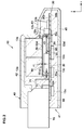
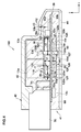
- FIG. 1B is a cross-sectional view taken along the line AA in a state where a part of the storage case of FIG. 1A is broken. It is a schematic diagram which shows a mode that the heat which generate
- the vehicle electronic control device in each embodiment of the present invention will be described in detail with reference to the drawings as appropriate.
- the x-axis, y-axis, and z-axis form a three-axis orthogonal coordinate system, and the z-axis direction corresponds to the vertical direction.
- FIG. 1A is a perspective view showing an electronic control device for a vehicle according to the present embodiment, showing a part of its housing case in a broken state, and FIG. 1B showing the state shown in FIG. 1A with its heat diffusion cover removed. It is a partial enlarged view.
- FIG. 2 is a cross-sectional view taken along the line AA in a state in which a part of the housing case of FIG. 1A is broken.
- illustration of the electronic parts other than the heat generating components and the connector and the resin part are omitted for convenience of explanation, and illustration of the resin part inside the thermal diffusion cover is omitted for convenience of explanation in FIG. is doing.
- the vehicle electronic control device 10 includes a heat generating component 20, a substrate 30, a housing case 40, a heat diffusion cover 50, a resin portion 60, a connector 70, and the like. Are mainly provided.
- the heat generating component 20 is typically composed of a plurality of switching elements such as FETs constituting a drive circuit.
- the heat generating component 20 generates heat by performing a switching operation when driving a motor or the like (not shown).
- a switching operation when driving a motor or the like (not shown).
- the heat generating component 20 since the heat generating component 20 generates heat during its operation and is densely mounted on the first mounting surface 30a of the substrate 30 by soldering or the like as shown in FIG. The region where 20 is mounted is likely to become hot during its operation.
- the substrate 30 is typically a circuit board such as a glass epoxy substrate, and has a first mounting surface 30a and a second mounting surface 30b which is the back surface of the first mounting surface 30a.
- a plurality of electronic components 13a and 13b, a heat generating component 20, and a connector 70 are mounted on the first mounting surface 30a, and a heat diffusion cover 50 that covers the heat generating component 20 is attached.
- a plurality of electronic components 13c are mounted on the second mounting surface 30b.
- the electronic component 13a mounted on the first mounting surface 30a is above and below the heat generating component 20 and the electronic component 13b mounted on the first mounting surface 30a and the electronic component 13c mounted on the second mounting surface 30b. It is a tall part with a high directional height.
- the housing case 40 is typically made of resin, and houses the electronic components 13a, 13b and 13c, the heat generating component 20, the substrate 30, the heat diffusion cover 50, and a part of the connector 70.
- the housing case 40 has a bag shape having an opening 41 opened to the outside at one end, and a part of the connector 70 projects from the opening 41 to the outside.
- a high top wall portion 42 extending from the opening 41 toward the positive direction of the x axis is provided in the central portion of the housing case 40 in the y axis direction.
- An electronic component 13a such as a capacitor is disposed.
- the upper wall portion other than the high top wall portion 42 of the housing case 40 is a low top wall portion 43 having a height lower than that of the high top wall portion 42.
- the heat generating component 20, the electronic component 13b, and the electronic component 13c each having a reduced height, are disposed.
- the vehicle electronic control device 10 can be downsized and the volume of the resin portion 60 can be reduced.
- the heat diffusion cover 50 is typically made of a metal such as iron, and is soldered to the first mounting surface 30a of the substrate 30 in a state of covering the heat generating component 20 with a predetermined interval from the heat generating component 20. It is attached.
- the heat diffusion cover 50 is a rectangular parallelepiped box-shaped member that is open at the bottom, and includes a recess 51 for storing the heat-generating component 20 and four side wall portions 52 a and 52 b provided around the recess 51. , 52c and 52d, and a plurality of holes not shown in the figure, which extend further below the lower end portions 53a, 53b, 53c and 53d of the four side wall portions 52a, 52b, 52c and 52d and are formed in the substrate 30. And a plurality of leg portions 54 that are fitted to the substrate 30 and fixed to the substrate 30 by soldering or the like, and four side wall portions 52a, 52b, 52c, and 52d are formed in correspondence with each other.
- a plurality of gap portions 55 and a top plate portion 56 are provided.
- the recess 51 is defined by four side wall portions 52 a, 52 b, 52 c and 52, and the top plate portion 56.
- a plurality of gaps are formed between the lower end portions 53 a, 53 b, 53 c and 53 d of the heat diffusion cover 50 and the first mounting surface 30 a of the substrate 30. 90 are each formed.
- the gap portion 55 and the gap portion 90 are provided to allow the resin to flow into the heat diffusion cover 50.
- the heat diffusion cover 50 is not limited to a rectangular parallelepiped box shape, and may be set to an arbitrary shape that can cover the heat generating component 20 with a predetermined interval from the heat generating component 20.
- the heat diffusion cover 50 has a through-hole that communicates the outside and the inside of the heat diffusion cover 50 so that the resin can easily flow into the heat diffusion cover 50.
- a notch may be provided in the top plate portion 56 or the like.
- the resin part 60 is formed by hardening after the resin material having fluidity filled in the housing case 40 flows into and out of the thermal diffusion cover 50. At this time, the resin material having fluidity filled in the housing case 40 flows into the inside of the heat diffusion cover 50 from the gap portion 55 and the gap portion 90 of the heat diffusion cover 50.
- the resin part 60 seals and fixes the heat generating component 20 covered with the heat diffusion cover 50 inside the heat diffusion cover 50, and also includes the electronic components 13a, 13b and 13c, the substrate 30, the heat diffusion cover 50, and the connector. A part of 70 is sealed and fixed inside the housing case 40.
- the shape of the heat diffusion cover 50 and the interval between the heat generation component 20 and the heat diffusion cover 50 are set so that a portion where the heat generation component 20 and the heat diffusion cover 50 are in direct contact does not occur. It is set so that a configuration in which the resin portion 60 is necessarily interposed between the diffusion cover 50 and the diffusion cover 50 is realized. Furthermore, the thermal conductivity of each of the resin resin portion 60, the resin housing case 40, and the metal heat diffusion cover 50 is set so that the heat conductivity of the heat diffusion cover 50 is maximized. .
- the heat generated in the heat generating component 20 is not unnecessarily accumulated in the vicinity thereof, and is diffusively transferred toward the heat diffusion cover 50 via the resin portion 60 inside the heat diffusion cover 50, so that the heat diffusion is performed.
- the heat diffusion cover 50 and the housing case 40 through the heat diffusion cover 50 while transferring heat inside the member of the heat diffusion cover 50 itself in a manner in which heat transfer to the resin portion 60 inside the cover 50 is suppressed again.
- the heat can be radiated to the outside of the housing case 40.
- the thermal conductivity of each of the resin-made resin part 60 and the resin-made housing case 40 is preferably set such that the thermal conductivity of the housing case 40 is larger than the thermal conductivity of the resin part 60. .
- the storage case 40 can efficiently and diffusively receive the heat generated in the heat generating component 20 via the heat diffusion cover 50 and the resin portion 60 and can reliably radiate the heat outside the storage case 40.
- the shape of the heat diffusion cover 50 and the interval between the heat generating component 20 and the heat diffusion cover 50 are portions where the temperature becomes higher than a predetermined temperature on the first mounting surface 30a side without the heat diffusion cover 50. It is determined in advance by simulation or actual measurement, and is determined by determining a region to be transferred from a location where the temperature becomes high in this way.
- a predetermined interval r1 is provided between the top plate portion 56 of the heat diffusion cover 50 and the heat generating component 20.
- a predetermined interval r2 is provided between the side wall portion 52a of the heat diffusion cover 50 and the heat generating component 20, and a predetermined interval is provided between the side wall portion 52c of the heat diffusion cover 50 and the heat generating component 20.
- r3 is provided.
- there is a relationship between the intervals r1, r2, and r3 such that the interval r1 ⁇ interval r2 ⁇ interval r3, and the heat diffusion cover 50 and the resin portion 60 inside thereof cover the heating element 20. Then, it is preferably unevenly distributed along the electronic component 13a on the positive direction side of the x-axis.
- the size between the intervals r1, r2, and r3 is thus large.
- the heat diffusion cover 50 and the resin portion 60 in the heat distribution cover 50 are unevenly distributed and the heat generated in the heat generation component 20 is generated via the resin portion 60 in the heat diffusion cover 50.
- the heat diffusion cover 50 is transferred to the heat diffusion cover 50 while conducting heat transfer in an increased manner in the heat transfer area on the positive side of the x-axis so as not to be unnecessarily trapped in the vicinity of the electronic component 13a.
- Heat is transferred from the heat diffusion cover 50 to the storage case 40 through the resin portion 60 between the storage case 40 and the heat diffusion cover 50 while transferring heat inside the members of the heat diffusion cover 50 itself.
- the heat is dissipated to the outside of Can. That is, the amount of heat dissipated to the electronic component 13a close to the heat generating element 20 can be further reduced, and the amount of heat dissipated to the electronic component 13b farther from the heat generating element 20 than the electronic component 13a is also reduced. It can be further reduced.
- a predetermined interval (not shown) is provided between the side wall portion 52b of the heat diffusion cover 50 and the heat generating component 20, and between the side wall portion 52d of the heat diffusion cover 50 and the heat generating component 20.
- the connector 70 has a fitting portion 70a that is a recess into which a mating connector (not shown) is fitted, and is a connection terminal that is formed by bending a metal member on a long plate and partially protrudes outside the connector 70. 71 is provided.
- the connector 70 is mounted on the first mounting surface 30 a of the substrate 30 with the connection terminals 71 soldered to the substrate 30. That is, one end of the connection terminal 71 is inserted into a not-shown through hole formed on the substrate 30 and soldered, and the other end is exposed at the fitting portion 70a so that the mating connector is not shown. It can be connected to connection terminals.
- the heat generating component 20 and the electronic components 13a and 13b are mounted on the first mounting surface 30a of the substrate 30 by soldering or the like, and the electronic component 13c is mounted on the second mounting surface 30b of the substrate 30 by soldering or the like. .
- the plurality of legs 54 of the heat diffusion cover 50 are fitted in correspondence with the plurality of holes of the first mounting surface 30a of the substrate 30, respectively. Thereafter, these are soldered to the substrate 30, and the thermal diffusion cover 50 is attached to the substrate 30.
- the attachment of the thermal diffusion cover 50 to the substrate 30 is not limited to soldering, and an attachment structure such as fastening or caulking may be used.
- connection terminal 71 of the connector 70 is soldered to the substrate 30, and the connector 70 is mounted on the substrate 30.
- the substrate 30 on which the electronic components 13a, 13b and 13c, the heat generating component 20 and the connector 70 are mounted and the heat diffusion cover 50 is attached is accommodated in the accommodating case 40 through the opening 41 of the accommodating case 40.
- a resin material having fluidity is introduced into the housing case 40 from the opening 41, filled, and then cured to cure the electronic components 13a and 13b in a state where the heat-generating component 20 is covered by the heat diffusion cover 50.
- 13c, the heat generating component 20, the substrate 30, the heat diffusion cover 50, and a part of the connector 70 are sealed and fixed in the housing case 40.
- the resin material having fluidity filled in the housing case 40 flows into the inside of the heat diffusion cover 50 from the gap portions 55 and 90 of the heat diffusion cover 50 and hardens, thereby generating heat.
- the component 20 is sealed and fixed inside the heat diffusion cover 50.
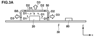
- FIG. 3A is a schematic diagram showing a state in which heat generated by the heat-generating component of the vehicle electronic control device in the present embodiment is transferred to the outside, and corresponds to FIG. 2 in terms of position.
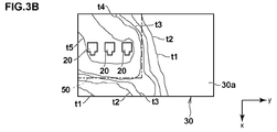
- FIG. 3B is a top view showing a temperature distribution around the heat generating component in a state in which the heat generating component is covered by the heat diffusion cover of the vehicle electronic control device in the present embodiment, and
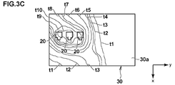
- FIG. It is a top view which shows temperature distribution around the heat-emitting component in the state which does not cover the heat-generating component with the thermal diffusion cover of the vehicle electronic control device.
- FIGS. 3B and 3C show only the heat generating component 20, the substrate 30, the heat diffusion cover 50, and the non-heat generating component 80 for convenience of explanation, and only the heat generating component 20, the substrate 30 and the heat diffusion cover 50 are shown in FIGS. 3B and 3C. Show.
- the heat generated in the heat generating component 20 is transferred radially through the resin portion 60 inside the heat diffusion cover 50 and reaches the heat diffusion cover 50 as indicated by an arrow D1 in FIG. 3A.
- the contact area of the heat generating component 20 with the resin portion 60 inside the heat diffusion cover 50 is relatively larger than the contact area of the heat generating component 20 with the substrate 30, so that the heat generated in the heat generating component 20 is transferred to the substrate 30.
- the rate of heating is relatively low.
- illustration of heat transfer directed downward is omitted.
- the heat that has reached the heat diffusion cover 50 is transferred inside the member of the heat diffusion cover 50 itself as indicated by an arrow D2 in FIG. 3A.
- the thermal conductivity of the resin part 60 inside the thermal diffusion cover 50 is lower than the thermal conductivity of the thermal diffusion cover 50, the heat transferred inside the members of the thermal diffusion cover 50 itself is inside the thermal diffusion cover 50. Heat transfer to the resin part 60 again is reliably suppressed.
- the heat transferred inside the member of the heat diffusion cover 50 itself is transferred in a radial manner from the heat diffusion cover 50 to the resin portion 60 outside the heat diffusion cover 50 as shown by an arrow D3 in FIG. .
- the heat that reaches the storage case 40 is radiated to the outside of the storage case 40.
- the heat received by the housing case 40 is diffused through the resin part 60 inside the heat diffusion cover 50, the heat diffusion cover 50, and the resin part 60 outside the heat diffusion cover 50. Since the heat has been transferred, the heat radiated to the outside of the housing case 40 is intensively radiated to the non-heat-generating components 80 such as the electronic components 13a and 13b existing outside the heat diffusion cover 50. Therefore, the heat effect on the non-heat generating component 80 can be reduced.
- FIG. 3B and FIG. 3C it is shown that the temperature increases in the order of temperatures t1, t2, t3.
- 3B and 3C show the temperature distribution when the heat-generating component 20 is heated under the same conditions except for the presence or absence of the thermal diffusion cover 50.
- the temperature rises as it approaches the heat generation component 20, but the temperature distribution corresponds to the arrangement region of the heat diffusion cover 50.
- the temperature of the highest temperature region where the heat generating component 20 is mounted is about t5.
- the heat generating component 20 is compared with the case where the heat generating component 20 is not covered with the heat diffusion cover 50. It can be seen that heat can be transferred and equalized while diffusing heat when heat is generated, and the maximum temperature of the vehicle electronic control device 10 can be reduced.
- 3B and 3C show the temperature distribution on the first mounting surface 30a of the substrate 30, the temperature distribution tendency on the second mounting surface 30b of the substrate 30 is also the same.
- the heat generating component 20, the substrate 30 on which the heat generating component 20 is mounted, and the storage case 40 for storing the heat generation component 20 and the substrate 30 are provided.
- the substrate is covered with the heat generating component 20 at a predetermined interval from the heat generating component 20.
- the heat generating component is further provided with a metal heat diffusion cover 50 that is attached to the first mounting surface 30a and sealed in the housing case 40 by the resin portion 60 filled in the housing case 40. It is possible to efficiently transfer the heat generated from 20 and dissipate the heat to the outside, thereby suppressing the occurrence of a locally high temperature region.
- the heat diffusion cover 50 and the resin portion 60 filled in the heat diffusion cover 50 are located on the heat generating component 20 along the other electronic components 13 a mounted on the substrate 30.
- the heat transfer area can be increased by avoiding other electronic components 13a having low heat resistance, and the amount of heat radiated to the other electronic components 13a having low heat resistance. Can be reduced.
- the housing case 40 since the thermal conductivity of the housing case 40 is set to be larger than the thermal conductivity of the resin portion 60, the housing case 40 has the thermal diffusion cover 50 and the resin portion 60. Thus, the heat generated in the heat-generating component 20 can be efficiently and diffusively received and reliably radiated from the outside of the housing case 40.
- FIG. 4 is a cross-sectional view of the electronic control device for a vehicle according to this embodiment in a state in which a part of the housing case is broken, and corresponds to FIG. 2 in terms of position.
- a heat diffusion cover 110 and a heat diffusion cover 120 are used instead of the heat diffusion cover 50 in the vehicle electronic control device 10 according to the first embodiment.
- This is the main difference. Therefore, in the present embodiment, the description will be made paying attention to such differences, and the same components as those in the first embodiment are denoted by the same reference numerals, and the description thereof will be omitted or simplified as appropriate.
- illustration of the resin part 60 inside the heat diffusion cover 110 and inside the heat diffusion cover 120 is omitted for convenience of explanation.
- the vehicle electronic control device 100 mainly includes the heat generating component 20, the substrate 30, the housing case 40, the resin part 60, the connector 70, the heat diffusion covers 110 and 120, and the fastening member 130. Prepare for.
- the heat diffusion cover 110 is typically a rectangular parallelepiped box-shaped member made of a metal such as iron, and covers the heat generating component 20 with a predetermined interval from the heat generating component 20.
- the attachment to the first mounting surface 30 a of the substrate 30 by the fastening member 130 is different from the configuration of the heat diffusion cover 50 in the vehicle electronic control device 10. That is, the heat diffusion cover 110 has a heat diffusion cover in the vehicle electronic control device 10 except that a through-hole 111 is formed through the top plate portion 56 so as to pass through the fastening member 130 in the plate thickness direction.
- the configuration is the same as 50.
- the heat diffusion cover 120 is typically a rectangular parallelepiped box-shaped member made of metal such as iron, like the heat diffusion cover 110, but corresponds to the region of the first mounting surface 30 a on which the heat generating component 20 is mounted.
- the second mounting surface 30b is attached to the second mounting surface 30b by a fastening member 130 in a state of covering the region of the second mounting surface 30b.
- Such a heat diffusion cover 120 covers the projection area projected from the first mounting surface 30a on which the heat generating component 20 is mounted onto the second mounting surface 30b when viewed from above, in the second mounting surface. It is attached to the surface 30b.
- the area covered by the thermal diffusion cover 120 is not limited to coincide with the projection area, but may be an area larger than that as long as the projection area is included as shown in FIG.
- the heat diffusion cover 120 is a rectangular parallelepiped box-shaped member that is open at the top, and includes a recess 121, four side wall portions 122a, 122b, 122c, and 122d provided around the recess 121, and four The upper end portions 123a, 123b, 123c, and 123d of the side wall portions 122a, 122b, 122c, and 122d are further extended above the upper ends 123a, 122b, 122c, and 122d, and are fitted to the plurality of holes that are formed in the substrate 30 and that are not shown.
- a plurality of leg portions 124, a plurality of gap portions 125 formed corresponding to each other between adjacent ones of the four side wall portions 122a, 122b, 122c, and 122d, and a bottom plate portion 126 are provided. .
- the concave portion 121 is defined by four side wall portions 122a, 122b, 122c and 122d, and a bottom plate portion 126.
- a plurality of gaps are formed between the upper end portions 123a, 123b, 123c and 123d of the heat diffusion cover 120 and the second mounting surface 30b of the substrate 30. 190 are formed.
- the gap portion 125 and the gap portion 190 are provided to allow the resin to flow into the heat diffusion cover 120.
- the bottom plate portion 126 is formed with a through-hole 127 that penetrates the fastening member 130 in the plate thickness direction.
- the height h2 from the second mounting surface 30b of the heat diffusion cover 120 when the heat diffusion cover 120 is attached to the second mounting surface 30b of the substrate 30 is such that the heat generating component 20 is mounted on the second mounting surface 30b. Therefore, the height is set to be lower than the height h1 of the heat diffusion cover 110 from the first mounting surface 30a when the heat diffusion cover 110 is attached to the first mounting surface 30a of the substrate 30. Thereby, since the space
- another electronic component such as a heat generating component may be mounted on the second mounting surface 30 b of the substrate 30.
- the heat diffusion cover 120 is made of the same material as the heat diffusion cover 110, there are great advantages in terms of cost and the like, but the heat conductivity is larger than the heat conductivity of the housing case 40 and the resin part 60.
- the metal material of the heat diffusion cover 110 may be formed using a different metal material.
- the resin part 60 is formed by hardening after the flowable resin material filled in the housing case 40 flows into and out of the heat diffusion cover 110 and the heat diffusion cover 120. At this time, the resin material having fluidity filled in the housing case 40 flows into the inside of the heat diffusion cover 110 from the gap portion 55 and the gap portion 90 of the heat diffusion cover 110, and the gap of the heat diffusion cover 120. It flows into the inside of the thermal diffusion cover 120 from the part 125 and the gap part 190.
- the resin part 60 seals and fixes the heat generating component 20 covered with the heat diffusion cover 110 inside the heat diffusion cover 110, and also electronic components 13a, 13b and 13c, the substrate 30, the connector 70, and the heat diffusion cover 110.
- the heat diffusion cover 120 and a part of the connector 70 are sealed and fixed inside the housing case 40.
- the fastening member 130 is typically made of resin, and has a head portion 130a having a diameter larger than the diameter of the through hole 127 at one end and a fastening portion 130b at the other end.
- the fastening member 130 is inserted into the through hole 111 formed in the heat diffusion cover 110, the through hole not shown in the figure formed in the substrate, and the through hole 127 formed in the heat diffusion cover 120, and the head portion 130a is inserted.
- the fastening portion 130b is fastened to the top plate portion 56 around the through hole 111 of the heat diffusion cover 110 by press-fitting, screwing or the like in a state where it is in contact with the bottom plate portion 126 around the through hole 127 of the heat diffusion cover 120.
- the heat diffusion cover 110 and the heat diffusion cover 120 are fixed to the substrate 30.
- the thermal conductivity of the fastening member 130 is set to be approximately the same as the thermal conductivity of the resin portion 60, and is set to be smaller than the thermal conductivity of each of the thermal diffusion cover 110 and the thermal diffusion cover 120.
- the heat generating component 20 and the electronic components 13a and 13b are mounted on the first mounting surface 30a of the substrate 30 by soldering or the like, and the electronic component 13c is mounted on the second mounting surface 30b of the substrate 30 by soldering or the like.
- the thermal diffusion cover 120 covers the thermal diffusion.
- the cover 110 and the heat diffusion cover 120 are attached to the substrate 30 by the fastening member 130 through the substrate 30.
- the fastening portion 130b of the fastening member 130 is inserted into the through hole 127 of the heat diffusion cover 120 from the outside of the heat diffusion cover 120.
- the fastening portion 130b of the fastening member 130 in which the through hole 127 and the through hole of the substrate are sequentially inserted into the through hole 111 of the heat diffusion cover 110 from the inside of the heat diffusion cover 110 is replaced with the head of the fastening member 130. Insert 130a until it contacts the bottom plate 126 around the through hole 127 of the heat diffusion cover 120.
- the fastening portion 130b of the fastening member 130 is fastened to the top plate portion 56 around the through hole 111 of the heat diffusion cover 110 by press fitting, screwing or the like, so that the heat diffusion cover 110 and the heat diffusion cover 120 are connected. It is fixedly attached to the substrate 30.
- the board 30 on which the connector 70 is mounted and the electronic components 13 a, 13 b and 13 c, the heat generating component 20, the heat diffusion cover 110 and the heat diffusion cover 120 are attached is inserted into the housing case 40 from the opening 41 of the housing case 40. To house.
- the resin material is poured into the housing case 40 from the opening 41 and filled, and then cured, thereby covering the heat generating component 20 with the heat diffusion cover 110 and covering the projection region with the heat diffusion cover 120.
- the electronic components 13a, 13b and 13c, the heat generating component 20, the substrate 30, the heat diffusion cover 110 and the heat diffusion cover 120, and a part of the connector 70 are sealed and fixed in the housing case 40.
- the resin material having fluidity filled in the housing case 40 flows into the heat diffusion cover 110 from the gap portion 55 and the gap portion 90 of the heat diffusion cover 110 and hardens, thereby generating a heat generating component. 20 is sealed inside the thermal diffusion cover 110.
- an electronic component such as another heat generating component is mounted on the second mounting surface 30b of the substrate 30 in the heat diffusion cover 120, the electronic component is similarly placed inside the heat diffusion cover 120. Seal.
- the state of the heat generation state when the heat generating component 20 of the vehicle electronic control device 100 in the present embodiment generates heat is the same as that described with reference to FIG. 3A and the heat generating component 20 of the vehicle electronic control device 100.
- the temperature distribution when heat is generated is the same as that described with reference to FIG. 3B.
- the heat diffusion cover 120 is provided in addition to the heat diffusion cover 110, the heat generated when the heat generating component 20 generates heat is diffused through the substrate 30. Heat is also transferred to the resin part 60 inside the cover 120. Thus, the heat transferred to the resin part 60 inside the heat diffusion cover 120 is diffused toward the heat diffusion cover 120 and transferred again to the resin part 60 inside the heat diffusion cover 120. Heat is transferred to the resin portion 60 between the heat diffusion cover 120 and the housing case 40 via the heat diffusion cover 120 while transferring the heat inside the member of the heat diffusion cover 120 itself in a suppressed manner, and the heat diffusion cover 120 and the housing are accommodated.
- the thermal conductivity of the fastening member 130 is set to be approximately the same as the thermal conductivity of the resin portion 60, and is set smaller than the thermal conductivity of each of the thermal diffusion cover 110 and the thermal diffusion cover 120.
- the heat generated when the heat generating component 20 or the like generates heat similarly.
- the maximum temperature of the vehicle electronic control device 10 can be further reduced by further diffusing and equalizing.
- no heat generating component is mounted in the heat diffusion cover 120, but the heat generating component is mounted in both the heat diffusion cover 110 and the heat diffusion cover 120, respectively. It may be.
- the first mounting surface is attached to the second mounting surface 30b which is the back surface of the first mounting surface 30a of the substrate 30.
- the heat diffusion cover 110 and the heat diffusion cover 120 are further provided with the resin fastening member 130 that fastens the heat diffusion cover 110 and the heat diffusion cover 120 to each other via the substrate 30, so that the heat diffusion cover is not soldered.
- 110 and the thermal diffusion cover 120 can be attached to the board 30, so that the layout for soldering to the board 30 and the board space for soldering are not required, and the mounting of electronic components and the circuit pattern
- the metal heat diffusion cover 110 and the heat diffusion cover 120 are not attached to the substrate by caulking, so the circuit on the substrate is caused by metal powder generated from the heat diffusion cover when caulking. The possibility that an event such as short-circuiting occurs can be reduced.
- the type, arrangement, number, and the like of the members are not limited to the above-described embodiments, and the constituent elements thereof are appropriately replaced with those having the same operational effects, and the gist of the invention is not deviated. Of course, it can be appropriately changed within the range.
- the present invention provides a vehicle electronic control device capable of suppressing the occurrence of a locally high temperature region by efficiently transferring heat generated from a heat-generating component and dissipating the heat to the outside. It is expected that it can be widely applied to electronic control devices for vehicles such as motorcycles because of its universal universal character.
Landscapes
- Engineering & Computer Science (AREA)
- Microelectronics & Electronic Packaging (AREA)
- Physics & Mathematics (AREA)
- Thermal Sciences (AREA)
- Cooling Or The Like Of Electrical Apparatus (AREA)
- Cooling Or The Like Of Semiconductors Or Solid State Devices (AREA)
- Casings For Electric Apparatus (AREA)
Abstract
Description
本発明の第1の実施形態における車両用電子制御装置につき、図面を適宜参照しながら、以下詳細に説明する。
まず、本実施形態における車両用電子制御装置の構成につき、図1Aから図2を参照しながら、以下詳細に説明する。
次に、本実施形態における車両用電子制御装置10の組み立て方法につき、図1Aから図2を参照しながら、以下詳細に説明する。
次に、本実施形態における車両用電子制御装置10における発熱部品20が発熱した際の発熱状態につき、更に図3Aから図3Cをも参照しながら、以下詳細に説明する。
次に、本発明の第2の実施形態における車両用電子制御装置につき、図面を適宜参照しながら、以下詳細に説明する。
<車両用電子制御装置の構成>
まず、本実施形態における車両用電子制御装置の構成につき、図4を参照しながら、以下詳細に説明する。
次に、本実施形態における車両用電子制御装置100の組み立て方法につき、図4を参照しながら、以下詳細に説明する。なお、本実施形態における車両用電子制御装置の組み立て方法において、第1の実施形態における車両用電子制御装置の組み立て方法と同一である工程については、その説明を省略又は簡略化する。
次に、本実施形態における車両用電子制御装置100における発熱部品20が発熱した際の発熱状態につき、以下詳細に説明する。
Claims (5)
- 発熱部品と、
前記発熱部品が実装された基板と、
前記発熱部品及び前記基板を収容する収容ケースと、
を有し、
前記収容ケースの内部に充填された樹脂により、前記発熱部品及び前記基板を前記収容ケース内に封止する車両用電子制御装置において、
前記発熱部品から所定間隔を設けて前記発熱部品を覆った状態で前記基板の第1の実装面に取り付けられると共に、前記収容ケースの内部に充填された前記樹脂により前記収容ケース内に封止される金属製の第1の熱拡散カバーを更に備えることを特徴とする車両用電子制御装置。 - 前記基板の前記第1の実装面の裏面である第2の実装面に取り付けられ、前記第1の実装面の前記発熱部品が実装される領域に対応する前記第2の実装面の領域を覆うと共に、前記収容ケースの内部に充填された前記樹脂により前記収容ケース内に封止される金属製の第2の熱拡散カバーを更に備えることを特徴とする請求項1記載の車両用電子制御装置。
- 前記第1の熱拡散カバーと前記第2の熱拡散カバーとを前記基板を介して互いに締結する樹脂製の締結部材を更に備えることを特徴とする請求項2記載の車両用電子制御装置。
- 前記第1の熱拡散カバー及び前記第2の熱拡散カバーの内部に充填された前記樹脂が、前記基板に実装される他の電子部品に沿いながら前記発熱部品に対して偏在して前記収容ケース内に配置されることを特徴とする請求項1から請求項3のいずれかに記載の車両用電子制御装置。
- 前記収容ケースの熱伝導率は、前記樹脂部の熱伝導率よりも大きいことを特徴とする請求項1から請求項4のいずれかに記載の車両用電子制御装置。
Priority Applications (1)
| Application Number | Priority Date | Filing Date | Title |
|---|---|---|---|
| CN201480047283.3A CN105493648B (zh) | 2013-08-30 | 2014-07-16 | 车辆用电子控制装置 |
Applications Claiming Priority (2)
| Application Number | Priority Date | Filing Date | Title |
|---|---|---|---|
| JP2013-180064 | 2013-08-30 | ||
| JP2013180064A JP6227937B2 (ja) | 2013-08-30 | 2013-08-30 | 車両用電子制御装置 |
Publications (1)
| Publication Number | Publication Date |
|---|---|
| WO2015029629A1 true WO2015029629A1 (ja) | 2015-03-05 |
Family
ID=52586204
Family Applications (1)
| Application Number | Title | Priority Date | Filing Date |
|---|---|---|---|
| PCT/JP2014/068902 Ceased WO2015029629A1 (ja) | 2013-08-30 | 2014-07-16 | 車両用電子制御装置 |
Country Status (3)
| Country | Link |
|---|---|
| JP (1) | JP6227937B2 (ja) |
| CN (1) | CN105493648B (ja) |
| WO (1) | WO2015029629A1 (ja) |
Cited By (1)
| Publication number | Priority date | Publication date | Assignee | Title |
|---|---|---|---|---|
| WO2018099620A1 (de) * | 2016-12-02 | 2018-06-07 | Robert Bosch Gmbh | Elektrische baugruppe |
Families Citing this family (6)
| Publication number | Priority date | Publication date | Assignee | Title |
|---|---|---|---|---|
| JP6966259B2 (ja) * | 2017-08-25 | 2021-11-10 | 日立Astemo株式会社 | 樹脂封止型車載電子制御装置 |
| JP2020004840A (ja) * | 2018-06-28 | 2020-01-09 | アルパイン株式会社 | 電子ユニットおよびその製造方法 |
| CN114467229A (zh) * | 2020-01-27 | 2022-05-10 | 日立安斯泰莫株式会社 | 电子控制装置 |
| JP7344141B2 (ja) * | 2020-01-27 | 2023-09-13 | 日立Astemo株式会社 | 電子制御装置 |
| JP2021118268A (ja) * | 2020-01-27 | 2021-08-10 | 日立Astemo株式会社 | 電子制御装置及びコネクタ |
| JP2021190495A (ja) * | 2020-05-27 | 2021-12-13 | 日立Astemo株式会社 | 電子制御装置 |
Citations (5)
| Publication number | Priority date | Publication date | Assignee | Title |
|---|---|---|---|---|
| JP2006313768A (ja) * | 2005-05-06 | 2006-11-16 | Denso Corp | 電子制御装置 |
| JP2009123812A (ja) * | 2007-11-13 | 2009-06-04 | Denso Corp | 放熱構造を有する電子制御装置 |
| JP2011023593A (ja) * | 2009-07-16 | 2011-02-03 | Denso Corp | 電子制御装置 |
| JP2011035106A (ja) * | 2009-07-31 | 2011-02-17 | Keihin Corp | 電子制御装置 |
| JP2012060014A (ja) * | 2010-09-10 | 2012-03-22 | Keihin Corp | 電子制御装置 |
Family Cites Families (1)
| Publication number | Priority date | Publication date | Assignee | Title |
|---|---|---|---|---|
| JP5384569B2 (ja) * | 2011-07-07 | 2014-01-08 | 日立オートモティブシステムズ株式会社 | 電子制御装置 |
-
2013
- 2013-08-30 JP JP2013180064A patent/JP6227937B2/ja active Active
-
2014
- 2014-07-16 CN CN201480047283.3A patent/CN105493648B/zh active Active
- 2014-07-16 WO PCT/JP2014/068902 patent/WO2015029629A1/ja not_active Ceased
Patent Citations (5)
| Publication number | Priority date | Publication date | Assignee | Title |
|---|---|---|---|---|
| JP2006313768A (ja) * | 2005-05-06 | 2006-11-16 | Denso Corp | 電子制御装置 |
| JP2009123812A (ja) * | 2007-11-13 | 2009-06-04 | Denso Corp | 放熱構造を有する電子制御装置 |
| JP2011023593A (ja) * | 2009-07-16 | 2011-02-03 | Denso Corp | 電子制御装置 |
| JP2011035106A (ja) * | 2009-07-31 | 2011-02-17 | Keihin Corp | 電子制御装置 |
| JP2012060014A (ja) * | 2010-09-10 | 2012-03-22 | Keihin Corp | 電子制御装置 |
Cited By (4)
| Publication number | Priority date | Publication date | Assignee | Title |
|---|---|---|---|---|
| WO2018099620A1 (de) * | 2016-12-02 | 2018-06-07 | Robert Bosch Gmbh | Elektrische baugruppe |
| KR20190089169A (ko) * | 2016-12-02 | 2019-07-30 | 로베르트 보쉬 게엠베하 | 전기 어셈블리 |
| US11122700B2 (en) | 2016-12-02 | 2021-09-14 | Robert Bosch Gmbh | Electrical assembly |
| KR102383265B1 (ko) * | 2016-12-02 | 2022-04-07 | 로베르트 보쉬 게엠베하 | 전기 어셈블리 |
Also Published As
| Publication number | Publication date |
|---|---|
| JP2015050274A (ja) | 2015-03-16 |
| JP6227937B2 (ja) | 2017-11-08 |
| CN105493648A (zh) | 2016-04-13 |
| CN105493648B (zh) | 2017-07-11 |
Similar Documents
| Publication | Publication Date | Title |
|---|---|---|
| JP6227937B2 (ja) | 車両用電子制御装置 | |
| JP6634316B2 (ja) | 樹脂封止型車載制御装置 | |
| CN102833970A (zh) | 电控单元 | |
| WO2018216465A1 (ja) | 回路構成体 | |
| US10880989B2 (en) | Electrical junction box | |
| US10820406B2 (en) | Circuit structure and electrical junction box | |
| JP6121879B2 (ja) | 制御ユニット | |
| JP2017069296A (ja) | 車載制御装置 | |
| CN104718804B (zh) | 电子设备 | |
| JP5259339B2 (ja) | 電子回路基板の収容装置 | |
| JP6982776B2 (ja) | 発熱電子部品の放熱装置、車載充電器、および車両 | |
| JP2014165227A (ja) | 電子制御装置 | |
| WO2019216366A1 (ja) | 回路構成体 | |
| KR101887439B1 (ko) | 전자 제어 장치 | |
| JP6544181B2 (ja) | 電子制御装置 | |
| JP6214970B2 (ja) | 車両用電子制御装置 | |
| JP4825248B2 (ja) | 電子制御装置 | |
| JP5888816B2 (ja) | 電子機器の放熱構造 | |
| JP2021106233A (ja) | 電子制御装置 | |
| JP2008277591A (ja) | 電子機器用ケース構造 | |
| JP2016129213A (ja) | 電子機器及びその製造方法 | |
| JP2013098388A (ja) | 電子部品の実装構造 | |
| JP2006179763A (ja) | 電子装置 | |
| JP2008098579A (ja) | 電子機器における発熱部品の放熱構造 | |
| JP2012199355A (ja) | 電子制御装置 |
Legal Events
| Date | Code | Title | Description |
|---|---|---|---|
| WWE | Wipo information: entry into national phase |
Ref document number: 201480047283.3 Country of ref document: CN |
|
| 121 | Ep: the epo has been informed by wipo that ep was designated in this application |
Ref document number: 14839117 Country of ref document: EP Kind code of ref document: A1 |
|
| NENP | Non-entry into the national phase |
Ref country code: DE |
|
| WWE | Wipo information: entry into national phase |
Ref document number: IDP00201602066 Country of ref document: ID |
|
| 122 | Ep: pct application non-entry in european phase |
Ref document number: 14839117 Country of ref document: EP Kind code of ref document: A1 |