WO2015029335A1 - 操作装置 - Google Patents
操作装置 Download PDFInfo
- Publication number
- WO2015029335A1 WO2015029335A1 PCT/JP2014/003996 JP2014003996W WO2015029335A1 WO 2015029335 A1 WO2015029335 A1 WO 2015029335A1 JP 2014003996 W JP2014003996 W JP 2014003996W WO 2015029335 A1 WO2015029335 A1 WO 2015029335A1
- Authority
- WO
- WIPO (PCT)
- Prior art keywords
- magnet
- coil
- cursor
- repulsive force
- force
- Prior art date
- Legal status (The legal status is an assumption and is not a legal conclusion. Google has not performed a legal analysis and makes no representation as to the accuracy of the status listed.)
- Ceased
Links
Images


Classifications
-
- G—PHYSICS
- G06—COMPUTING OR CALCULATING; COUNTING
- G06F—ELECTRIC DIGITAL DATA PROCESSING
- G06F3/00—Input arrangements for transferring data to be processed into a form capable of being handled by the computer; Output arrangements for transferring data from processing unit to output unit, e.g. interface arrangements
- G06F3/01—Input arrangements or combined input and output arrangements for interaction between user and computer
- G06F3/03—Arrangements for converting the position or the displacement of a member into a coded form
- G06F3/033—Pointing devices displaced or positioned by the user, e.g. mice, trackballs, pens or joysticks; Accessories therefor
- G06F3/0338—Pointing devices displaced or positioned by the user, e.g. mice, trackballs, pens or joysticks; Accessories therefor with detection of limited linear or angular displacement of an operating part of the device from a neutral position, e.g. isotonic or isometric joysticks
-
- G—PHYSICS
- G05—CONTROLLING; REGULATING
- G05G—CONTROL DEVICES OR SYSTEMS INSOFAR AS CHARACTERISED BY MECHANICAL FEATURES ONLY
- G05G1/00—Controlling members, e.g. knobs or handles; Assemblies or arrangements thereof; Indicating position of controlling members
- G05G1/08—Controlling members for hand actuation by rotary movement, e.g. hand wheels
- G05G1/10—Details, e.g. of discs, knobs, wheels or handles
-
- G—PHYSICS
- G05—CONTROLLING; REGULATING
- G05G—CONTROL DEVICES OR SYSTEMS INSOFAR AS CHARACTERISED BY MECHANICAL FEATURES ONLY
- G05G5/00—Means for preventing, limiting or returning the movements of parts of a control mechanism, e.g. locking controlling member
- G05G5/03—Means for enhancing the operator's awareness of arrival of the controlling member at a command or datum position; Providing feel, e.g. means for creating a counterforce
-
- G—PHYSICS
- G05—CONTROLLING; REGULATING
- G05G—CONTROL DEVICES OR SYSTEMS INSOFAR AS CHARACTERISED BY MECHANICAL FEATURES ONLY
- G05G9/00—Manually-actuated control mechanisms provided with one single controlling member co-operating with two or more controlled members, e.g. selectively, simultaneously
- G05G9/02—Manually-actuated control mechanisms provided with one single controlling member co-operating with two or more controlled members, e.g. selectively, simultaneously the controlling member being movable in different independent ways, movement in each individual way actuating one controlled member only
- G05G9/04—Manually-actuated control mechanisms provided with one single controlling member co-operating with two or more controlled members, e.g. selectively, simultaneously the controlling member being movable in different independent ways, movement in each individual way actuating one controlled member only in which movement in two or more ways can occur simultaneously
- G05G9/047—Manually-actuated control mechanisms provided with one single controlling member co-operating with two or more controlled members, e.g. selectively, simultaneously the controlling member being movable in different independent ways, movement in each individual way actuating one controlled member only in which movement in two or more ways can occur simultaneously the controlling member being movable by hand about orthogonal axes, e.g. joysticks
-
- G—PHYSICS
- G06—COMPUTING OR CALCULATING; COUNTING
- G06F—ELECTRIC DIGITAL DATA PROCESSING
- G06F3/00—Input arrangements for transferring data to be processed into a form capable of being handled by the computer; Output arrangements for transferring data from processing unit to output unit, e.g. interface arrangements
- G06F3/01—Input arrangements or combined input and output arrangements for interaction between user and computer
- G06F3/016—Input arrangements with force or tactile feedback as computer generated output to the user
-
- G—PHYSICS
- G06—COMPUTING OR CALCULATING; COUNTING
- G06F—ELECTRIC DIGITAL DATA PROCESSING
- G06F3/00—Input arrangements for transferring data to be processed into a form capable of being handled by the computer; Output arrangements for transferring data from processing unit to output unit, e.g. interface arrangements
- G06F3/01—Input arrangements or combined input and output arrangements for interaction between user and computer
- G06F3/03—Arrangements for converting the position or the displacement of a member into a coded form
- G06F3/033—Pointing devices displaced or positioned by the user, e.g. mice, trackballs, pens or joysticks; Accessories therefor
- G06F3/0354—Pointing devices displaced or positioned by the user, e.g. mice, trackballs, pens or joysticks; Accessories therefor with detection of 2D relative movements between the device, or an operating part thereof, and a plane or surface, e.g. 2D mice, trackballs, pens or pucks
- G06F3/03548—Sliders, in which the moving part moves in a plane
-
- G—PHYSICS
- G06—COMPUTING OR CALCULATING; COUNTING
- G06F—ELECTRIC DIGITAL DATA PROCESSING
- G06F3/00—Input arrangements for transferring data to be processed into a form capable of being handled by the computer; Output arrangements for transferring data from processing unit to output unit, e.g. interface arrangements
- G06F3/01—Input arrangements or combined input and output arrangements for interaction between user and computer
- G06F3/03—Arrangements for converting the position or the displacement of a member into a coded form
- G06F3/033—Pointing devices displaced or positioned by the user, e.g. mice, trackballs, pens or joysticks; Accessories therefor
- G06F3/038—Control and interface arrangements therefor, e.g. drivers or device-embedded control circuitry
- G06F3/0383—Signal control means within the pointing device
-
- G—PHYSICS
- G06—COMPUTING OR CALCULATING; COUNTING
- G06F—ELECTRIC DIGITAL DATA PROCESSING
- G06F2203/00—Indexing scheme relating to G06F3/00 - G06F3/048
- G06F2203/01—Indexing scheme relating to G06F3/01
- G06F2203/015—Force feedback applied to a joystick
Definitions
- This disclosure relates to an operating device to which an operating force is input.
- Patent Document 1 discloses an operation device that presents a tactile sensation to a finger or the like of an operator who is operating the tactile presentation member by applying a force from an actuator to a tactile presentation member as an operation unit to which an operation force is input.
- This actuator has a magnet held on the first yoke plate and a coil held by a coil fixing member that can move integrally with the tactile sense providing member. Magnetic field lines generated by the magnet are guided to the coil by the second yoke plate disposed on the opposite side of the magnet and the first yoke plate with respect to the coil, and electromagnetic force (Lorentz force) generated by energizing the coil is presented as a tactile sensation. Acts on the member.
- JP2004-112929A JP3997872 (B2)
- the operating device according to Patent Document 1 holds a magnet fixedly and holds a coil movably.
- the present inventor has studied an operating device in which a coil is fixedly held on a holding body and a magnet is held on a movable body.
- the yoke plate disposed on the opposite side of the magnet with respect to the coil is fixedly held by the holding body together with the coil.
- the magnetic attraction force acting between the yoke plate and the magnet acts across the holding body and the moving body, and the moving body is pressed against the holding body by the magnetic attraction force. . Therefore, when the moving body moves relative to the holding body, the frictional force generated between the moving body and the holding body is increased, so that the operation provided on the moving body is caused by the sliding resistance due to the frictional force. The operability at the time of operating the part is deteriorated.
- the present disclosure provides an operation device that holds a coil on a holding body, holds a magnet on a movable body that can move integrally with the operation unit, and applies Lorentz force generated by energizing the coil to the operation unit.
- the purpose was to improve the operability of the parts.
- the moving body is provided so as to be movable while integrally holding an operating unit to which an operating force is input and a magnet.
- a coil arranged with a gap with respect to the moving path of the magnet by the movement of the moving body, and a yoke arranged on the opposite side of the magnet with respect to the coil and guiding the lines of magnetic force generated by the magnet to the coil Is held by a holding body.
- the holding body supports the moving body in contact with the coil and the yoke from the side.
- the Lorentz force generated by energizing the coil can be applied to the operation unit.
- a magnetic attractive force acts between the moving body and the holding body between the magnet and the yoke
- a large frictional force acts on the contact portion between the holding body and the moving body as described above.
- the repulsive force generating unit generates a repulsive force between the moving body and the holding body. For this reason, the contact pressure between the holding body and the moving body is reduced, the frictional force is also reduced, and the operability of the operation unit can be improved.
- the magnet provided in the said moving body and the said holding body may be sufficient, for example.
- at least one of the magnet of the moving body and the magnet of the holding body may be an electromagnet.
- the magnitude of the repulsive force can be adjusted by controlling the energization of the electromagnet. For this reason, the sliding resistance acting on the moving body can also be adjusted to an appropriate value, and the operability of the operation unit can be further improved.
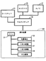
- the operating device 100 is mounted on a vehicle and constitutes a display system 10 together with a navigation device 20 and the like as shown in FIG.
- the operation device 100 is installed at a position adjacent to the armrest 19 at the center console of the vehicle, and exposes the operation knob 70 in a range where the operator's hand H can be easily reached.
- the operation knob 70 is displaced in the direction of the input operation force when the operation force is input by the operator's hand H or the like.
- the navigation device 20 includes a display 21 installed in the instrument panel of the vehicle, and the display screen 22 of the display 21 is exposed toward the driver's seat.
- the display screen 22 displays a plurality of buttons (so-called icons) associated with predetermined functions, a cursor 80 (in this example, configured as a so-called mouse pointer) for selecting an arbitrary button, and the like.
- buttons such as icons
- a cursor 80 in this example, configured as a so-called mouse pointer
- the cursor 80 moves on the display screen 22 in a direction corresponding to the input direction of the operation force.
- the display 21 is connected to the operation device 100 via a multimedia device 29 together with an audio 25, an air conditioner (A / C) 27, and the like.
- the display 21 and the air conditioner 27 are connected to the multimedia device 29 using CAN communication via CAN (Controller Area Network), and the audio 25 is connected to the multimedia device 29 using MOST (Media Oriented Systems). Transport) communication is used.
- a drawing drawing command is transmitted from the multimedia device 29 to the display 21, and various control signals are also transmitted from the multimedia device 29 to the audio 25 and the air conditioner 27.
- drawing information relating to the drawing displayed on the display 21 is transmitted from the multimedia device 29 to the operation device 100, and the cursor position corresponding to the position of the operation knob 70 is transmitted from the operation device 100 to the multimedia device 29. Information is being sent.
- the operating device 100 is electrically configured by an ECU 31, a position detection sensor 33, an X reaction force adjusting unit 35, a Y reaction force adjusting unit 37, a repulsive force adjusting unit 39, and the like, and the electric power necessary for the operation of each of these components is illustrated. Supplied from the omitted battery.
- the position detection sensor 33 detects the position of the operation knob 70, and the ECU 31 controls the X reaction force adjustment unit 35, the Y reaction force adjustment unit 37, the repulsive force adjustment unit 39, and the like based on the position and the drawing information.
- the X reaction force adjustment unit 35 adjusts the reaction force in the x-axis direction (left-right direction) applied to the operation knob 70.
- the Y reaction force adjustment unit 37 adjusts the reaction force in the y-axis direction (front-rear direction) applied to the operation knob 70.
- the repulsive force adjustment unit 39 adjusts the repulsive force that acts between the knob base 71 provided with the operation knob 70 and the housing 50 (see FIG. 3) of the operation device 100 that supports the knob base 71.
- the configuration of the operating device 100 will be described in detail.
- the side on which the operation knob 70 is provided is referred to as the upper side, and the former is the left-right direction and the latter is the front-rear direction among the x-axis direction and the y-axis direction in which the operation knob 70 is movable.
- the arrangement form of the operating device 100 is not limited to this.
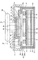
- the operation device 100 is mechanically configured by the operation knob 70 and the housing 50 described above.
- the operation knob 70 is provided to be movable relative to the housing 50 in the x-axis direction and the y-axis direction along the virtual operation plane OP.
- a range in which the operation knob 70 is movable in each of the x-axis direction and the y-axis direction is defined in advance by the housing 50.
- the housing 50 is a housing that accommodates the components such as the circuit boards 51 and 52 while supporting the operation knob 70 so as to be relatively movable.
- the circuit boards 51 and 52 are fixed in the housing 50 in a posture in which the plate surface direction is aligned with the operation plane OP and parallel to the upper and lower sides by a stud 53a extending from a bottom lid 53 fixed to the lower surface of the housing 50.
- a control circuit centered on a microcomputer such as the ECU 31 is mounted.
- the upper circuit board 52 is provided with four coils 41 to 44, and the operation knob 70 is provided with four magnets 61 to 64. It is provided so as to be movable together.
- Each of the coils 41 to 44 is formed by winding a wire made of a nonmagnetic material such as copper around the bobbin 49 a as a winding 49.
- the current supplied to each winding 49 is individually controlled for each winding 49 by the X reaction force adjusting unit 35 or the Y reaction force adjusting unit 37.
- the coils 41 to 44 are mounted on the circuit board 52 in a posture in which the winding axis direction of the winding 49 is along the z axis perpendicular to the operation plane OP. Each of the coils 41 to 44 is held on the circuit board 52 in such a direction that the winding 49 extends along the x-axis direction and the y-axis direction so as to be a substantially square shape in the z-axis view.
- the above four coils 41 to 44 are arranged in a “+” shape. That is, as shown in FIG. 4, a pair of coils 41 and 43 are arranged at intervals in the x-axis direction. In addition, a pair of coils 42 and 44 are arranged at intervals in the y-axis direction. With such an arrangement, a central region 45 surrounded by four coils 41 to 44 is formed.
- the magnets 61 to 64 are neodymium magnets or the like, and are formed in a plate shape. Each of the magnets 61 to 64 has a quadrilateral shape in which the length of each side 69 (see FIG. 4) is equal to each other, and is formed in a substantially square shape in this embodiment.
- the magnets 61 to 64 are held by the knob base 71 in a posture in which the direction of each side 69 is along the x axis or the y axis.
- the four magnets 61 to 64 are arranged in two each in the x-axis direction and the y-axis direction. In other words, the four magnets 61 to 64 are arranged one by one in the first to fourth quadrants.
- the four magnets 61 to 64 each have a facing surface 68 (see FIG. 3) facing the circuit board 52 while being held by the knob base 71.
- the opposing surfaces 68 of the four magnets 61 to 64 are substantially square and have a smooth plane.
- Each facing surface 68 faces two of the four coils 41 to 44 in the z-axis direction through an opening 50d formed in the housing 50.
- Each of the magnets 61 to 64 is magnetized in the z-axis direction, and the opposite surface 68 and the opposite surface of one magnet have different polarities.
- the polarities of the facing surfaces 68 of the magnets 61 to 64, that is, the two magnetic poles of the N pole and the S pole are staggered with respect to the adjacent magnets in the x-axis direction and the y-axis direction.
- the operating device 100 has a coil side yoke 56 and a magnet side yoke 72 that guide the lines of magnetic force generated by the magnets 61 to 64 to the coils 41 to 44 facing the magnets in the z-axis direction.
- the magnet side yoke 72 and the coil side yoke 56 are formed in a rectangular plate shape from a magnetic material. Specifically, the yokes 72 and 56 have a flat plate shape that does not have irregularities.
- the magnet side yoke 72 is disposed on the operation knob 70 side with respect to the magnets 61 to 64, and the coil side yoke 56 is disposed on the opposite side of the operation knob 70 with respect to the coils 41 to 44. That is, the magnets 61 to 64 and the coils 41 to 44 are located between the yokes 72 and 56.
- the magnet side yoke 72 and the coil side yoke 56 form a part of a magnetic circuit that becomes a path of magnetic lines of force generated by the magnets 61 to 64. As a result, the lines of magnetic force leaking out of the magnetic circuit can be reduced.
- the coils 41 to 44 are arranged at the passage positions of the magnetic lines of force between the yokes 72 and 56, thereby concentrating the magnetic lines of force on the coils 41 to 44.
- the opposing surfaces 56a and 72a of the coil side yoke 56 and the magnet side yoke 72 that are opposed to each other are viewed from the z-axis direction when an integrated body composed of the four magnets 61 to 64 is called an assembled magnet 65 (see FIG. 4).
- the sizes of the facing surfaces 56a and 72a are set so that the assembled magnet 65 does not protrude from the facing surfaces 56a and 72a. That is, the length of one side of the opposing surfaces 56a and 72a having a rectangular shape is set to be equal to or longer than the outer edge lengths Lmx and Lmy (see FIG. 4) of the assembled magnet 65.
- the length of one side of the facing surface 72 a is the same as the lengths Lmx and Lmy between the outer edges of the assembled magnet 65.
- the housing 50 includes a main body portion 50a that houses the four coils 41 to 44, the coil side yoke 56, and the circuit boards 51 and 52, and a support portion 50b that supports the knob base 71.
- the main body portion 50a has a cylindrical shape extending in the z-axis direction
- the support portion 50b has a plate shape extending from the cylindrical end portion on the operation knob 70 side of the main body portion 50a to the inside of the cylinder.
- the main body 50a and the support 50b are integrally formed of resin.
- the circuit board 52 is fixed to the main body 50a via a bottom lid 53 attached to the end of the main body 50a opposite to the operation knob 70, and the coils 41 to 44 are mounted on the circuit board 52. ing.
- the coil side yoke 56 is mounted on the surface of the circuit board 52 opposite to the side on which the coils 41 to 44 are mounted. That is, the coils 41 to 44 and the coil side yoke 56 are held by the main body 50 a via the circuit board 52 and the bottom lid 53. That is, the housing 50, the circuit board 52, and the bottom lid 53 function as a “holding body” that holds the coils 41 to 44 and the coil side yoke 56.
- a cover 57 that covers the knob base 71 is attached to the cylinder end on the operation knob 70 side of the main body 50a. Therefore, the housing 50, the bottom cover 53, the cover 57, and the circuit boards 51 and 52 are fixed to predetermined positions in the instrument panel in an undisplaceable state.
- the knob base 71 is held by the housing 50 in a state where it can be moved inside the cover 57.
- the knob base 71 holds four magnets 61 to 64 and a magnet side yoke 72.
- an operation knob 70 is attached to the knob base 71. Therefore, when the operation force is input to the operation knob 70, the knob base 71, the magnets 61 to 64, and the magnet side yoke 72 move together with the operation knob 70. That is, the knob base 71 functions as a “moving body” that moves relative to the housing 50 while contacting the housing 50 while holding the magnets 61 to 64 and the like.
- the operation knob 70 functions as an “operation unit” to which an operator's operation force is input.
- the knob base 71 includes a holding portion 71a, an extending portion 71b, an abutting portion 71c, and a bracket 71d described below.
- the holding portion 71a has a cylindrical shape that holds the magnet side yoke 72 and the magnets 61 to 64 inside.
- the extending portion 71b has a plate shape extending in parallel with the operation plane OP from the cylindrical end portion (lower end) of the holding portion 71a.
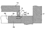
- the contact portion 71c has a pin shape protruding toward the housing 50 from the extended end portion of the extended portion 71b.
- the contact part 71c is provided in three or more places of the extension part 71b. In the example shown in FIG. 3, the contact portions 71c are provided at the four corners of the extending portion 71b having a rectangular shape.
- the support portion 50b of the housing 50 forms a slide contact surface 50c extending in parallel to the operation plane OP. And the above-mentioned some contact part 71c contact
- the knob base 71 is supported by the housing 50 from the coils 41 to 44 and the coil side yoke 56 in a state where it can move in the operation plane OP direction.
- the bracket 71d has a shape extending in the z-axis direction along the outer edge of the assembled magnet 65, and is provided at each of the four corners of the assembled magnet 65 in the example of FIG.
- the holding portion 71a, the extending portion 71b, and the contact portion 71c are resin-molded so as to be integrally formed.
- the bracket 71d is made of a nonmagnetic material such as resin and is attached to the extending portion 71b.
- a permanent magnet 78 is disposed inside each contact portion 71 c, and an electromagnet 58 is attached to the slide contact surface on the support portion 50 b of the housing 50 facing the permanent magnet 78. It is buried so as not to disturb the flatness of 50c.
- Each permanent magnet 78 is magnetized in the z-axis direction. Although the polarities of N and S are illustrated in FIG. 5 for convenience, the polarity of the permanent magnet 78 is not limited to this. Further, the electromagnet 58 is configured by winding a coil 58b around a bobbin 58a having an axis in the z-axis direction.
- the repulsive force adjustment unit 39 (see FIG. 2) generates repulsive force between the support portion 50b and the contact portion 71c by energizing the coil 58b with current so that the electromagnet 58 repels the permanent magnet 78. Let Further, the repulsive force adjusting unit 39 adjusts the magnitude of the repulsive force by adjusting the magnitude of the current based on a control signal from the ECU 31.
- the operation principle of the X reaction force adjustment unit 35 and the Y reaction force adjustment unit 37 will be described.
- FIG. 4 an example in which an operation reaction force in the x-axis direction is generated at a reference position where the center of the assembled magnet 65 overlaps the center of the central region 45 in the z-axis direction will be described.
- the following current is supplied to the coils 42 and 44 arranged in the y-axis direction by the X reaction force adjusting unit 35.
- the coil 44 is supplied with a clockwise current when viewed from above in the direction from the coil side yoke 56 to the magnet side yoke 72.
- the coil 42 is energized with a counterclockwise current that is reverse to the coil 44.
- the portion extending in the x-axis direction and overlapping the magnet 61 in the z-axis direction is a direction from the coil 44 to the coil 42 along the y-axis (hereinafter referred to as the following).
- “Rearward direction”) Lorentz force (hereinafter referred to as electromagnetic force) Fy1 is generated.
- a portion extending in the x-axis direction and overlapping with the magnet 64 in the z-axis direction is a direction (hereinafter referred to as “front” from the coil 42 to the coil 44 along the y-axis.
- Electromagnetic force Fy2 of “direction” is generated.
- electromagnetic forces Fy3 and Fy4 in the backward direction and the forward direction are respectively generated in portions extending in the x-axis direction and overlapping with the magnets 62 and 63 in the z-axis direction. .
- These y-axis electromagnetic forces Fy1 and Fy3 and electromagnetic forces Fy2 and Fy4 cancel each other.
- a portion extending in the y-axis direction and overlapping with the magnets 61 and 64 in the z-axis direction is a direction (from the coil 41 to the coil 43 along the x-axis (
- electromagnetic forces Fx1 and Fx2 of “left direction” are generated.
- left electromagnetic forces Fx3 and Fx4 are generated in portions extending in the y-axis direction and overlapping the magnets 62 and 63 in the z-axis direction.
- the X reaction force adjusting unit 35 can apply these electromagnetic forces Fx1 to Fx4 to the operation knob 70 as operation reaction forces in the x-axis direction.
- a Y reaction force is applied so that a counterclockwise current is supplied to the coil 41 and a clockwise current is supplied to the coil 43.
- the adjustment unit 37 may perform current control. Further, the magnitude of the operation reaction force in each axial direction is adjusted by controlling the magnitude of the current supplied to each of the coils 41 to 44 from the X reaction force adjustment section 35 and the Y reaction force adjustment section 37 described above. Is done. In addition, the direction of the operation reaction force acting on the assembled magnet 65 is switched by changing the direction of the current supplied to the coils 41 to 44.
- the windings 49 of the coils 41 to 44 have a predetermined length or more. It is necessary to overlap the assembled magnet 65 in the z-axis direction. Specifically, in order to generate the electromagnetic forces Fx1 to Fx4 in the predetermined x-axis direction, the portions extending in the y-axis direction in the windings 49 of the coils 42 and 44 are set to a length longer than a predetermined length. It is necessary to overlap with the magnet 65.
- an effective length Lex in the x-axis direction is defined in advance.
- the sides 69 adjacent to each other on the parallel facing surfaces 68 are in contact with each other without a gap.
- the length Lmx between the outer edges in the x-axis direction is shorter than the length Lcx between the outer edges 46a in the pair of coils 41 and 43 arranged in the x-axis direction.
- the length Lmy between the outer edges in the y-axis direction of the magnet assembly 65 is shorter than the length Lcy between the outer edges 47a in the y-axis direction of the pair of coils 42 and 44 arranged in the y-axis direction.
- the range where the coil 42 overlaps is small. Therefore, the effective length Ley in the y-axis direction of the coil 42 decreases.
- the overlapping range of the opposing surfaces 68 of the magnets 64 and 61 located on the front side (front direction) in the moving direction and the coil 44 located on the front side in the moving direction becomes large. For this reason, the effective length Ley in the y-axis direction of the coil 44 increases.
- the sum of the effective lengths Ley in the y-axis direction of the coils 42 and 44 is maintained even when the assembled magnet 65 moves in the y-axis direction. For this reason, the electromagnetic forces Fx1 to Fx4 in the x-axis direction that can be generated can be maintained.
- the assembled magnet 65 fixed to the knob base 71 side moves relative to the coils 41 to 44 fixed to the housing 50 side.
- the coils 41 to 44 are fixed to the knob base 71 side and the assembled magnet 65 is fixed to the housing 50 side, the following occurs. That is, since it is necessary to arrange the assembled magnet 65 over the entire movement range of the coils 41 to 44, it is necessary to increase the area of the assembled magnet 65 in the x-axis and y-axis directions, and the size of the operating device 100 is increased. Invite. On the other hand, in this embodiment, since the assembled magnet 65 is moved, the assembled magnet 65 can be downsized.
- the effective lengths Lex and Ley are maintained regardless of the movement position of the magnet assembly 65. Therefore, it is possible to secure the strength of the electromagnetic forces Fy1 to Fy4 and Fx1 to Fx4 that can be generated regardless of the moving position of the assembled magnet 65, while adopting a structure for moving the assembled magnet 65. Therefore, the operating device 100 is realized in which the individual magnets 61 to 64 are reduced in size and the generated electromagnetic force is ensured.
- the wiring connecting the coils 41 to 44 and the circuit board 52 bends and deforms every time the coils 41 to 44 move. It will be. Therefore, there is a concern about the durability of the wiring.
- the present embodiment since the structure in which the magnet assembly 65 that does not require wiring is moved is adopted, bending deformation of the wiring caused by the movement of the coils 41 to 44 is eliminated. Therefore, the concern about the durability of the wiring described above can be solved.
- produce a repulsive force between the support part 50b and the contact part 71c via the repulsive force adjustment part 39 employ
- the operability of the operating device 100 is further improved by the ECU 31 executing the following process.
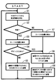
- the flowchart in FIG. 7 represents a process that is repeatedly executed by the ECU 31 while any display is being made on the display screen 22.
- S1 represents a step: the same applies hereinafter
- screen information of an image displayed on the display screen 22 of the display 21 via the multimedia device 29 is obtained. To be acquired.
- S2 it is determined whether or not the screen is a map screen. If the screen is a map screen (S2: Y), the process proceeds to S3.
- the position of the operation knob 70 is detected via the position detection sensor 33, whereby the position of the cursor 80 on the display screen 22 is detected.
- repulsive force adjustment is performed so that an appropriate sliding resistance acts when operating the operation knob 70, that is, an appropriate frictional force acts between the support portion 50b and the contact portion 71c.
- a current is passed through the coil 58b, and the process proceeds to S1 described above.
- a map 22a and the map 22a are enlarged or reduced or other commands are displayed on the display screen 22.
- various buttons 22b for inputting The cursor 80 is moved according to the operation of the operation knob 70 in order to specify a destination on the map 22a or to press the button 22b.
- a current is passed through the coils 41 to 44 for generating the reaction force in the x-axis direction and the y-axis direction. More specifically, by adjusting the current supplied to the coils 41 to 44 via the X reaction force adjustment unit 35 and the Y reaction force adjustment unit 37, the operation knob 70 in a state where no external force is applied is moved. It can be moved to any position in the range.
- the energization control for the coils 41 to 44 when executing such processing is disclosed in, for example, JP 2005-141675 A, and will not be described in detail here.
- a current is supplied to the repulsive force adjusting coil 58b, and the process proceeds to S1 described above. More specifically, when the position of the operation knob 70 is disposed at a position corresponding to the center of the button 22b or the like, the current flowing through the coil 58b is reduced to reduce the repulsive force and contact the support portion 50b. Processing to increase the frictional force acting between the portion 71c is performed. By this processing, the operator is prevented from passing the center of the desired button 22b or the like, and the cursor 80 can be easily moved to the center.
- the center may not be a single point, but may be a range having a certain area.
- buttons 22m to 22r are displayed on the display screen 22 as in the destination search method selection screen for car navigation shown in FIG. 9A
- a reaction force as shown in 9 (A) acts on the operation knob 70. That is, when the cursor 80 moves from the button 22m to the button 22n, a reaction force that moves the operation knob 70 to a position corresponding to the center of the button 22n is applied to the operation knob 70 by the process of S8.
- the reaction force acts in the forward direction with the arrow A immediately after the cursor 80 moves from the top of the button 22m to the top of the button 22n, and when the cursor 80 tries to pass through the center of the button 22n, Acts as a resistance force in the reverse direction.
- control is performed so that the frictional force is increased at the center of each button 22m to 22r. Therefore, the operation of arranging the cursor 80 at the center of the desired button among the desired buttons 22m to 22r is further facilitated. Further, when the cursor 80 disposed at the center of a desired button is moved once, it is necessary to move the operation knob 70 against the frictional force, so that the operator has an obvious intention. The cursor 80 can be moved only when 70 is moved. In S9, when the cursor 80 is not at the center of the button 22b or the like, the repulsive force is applied and the frictional force is reduced.
- the contact pressure between the support portion 50b and the contact portion 71c is reduced by the repulsive force acting between the permanent magnet 78 and the electromagnet 58, and the friction force acting between the two is also reduced.
- This can reduce the operability of the controller device 100.
- the magnitude of the repulsive force can be adjusted by controlling the energization to the coil 58b, the operating device 100 at the time of operation such as moving the cursor 80 to the center of a desired button as described above. The operability can be further improved.
- the operation knob 70 is the operation unit
- the knob base 71 is the moving body
- the coil side yoke 56 is the yoke
- the housing 50 is the circuit board 52 and the bottom lid 53 are the holding body
- 58 is a repulsive force generation unit
- display 21 is an image display unit
- buttons 22b and 22m to 22r are in an instruction area
- display screen 22 is in a cursor movement area
- X reaction force adjustment unit 35 and Y reaction force adjustment unit 37 are coils. Each corresponds to a control unit.
- control by a so-called VCM (voice coil motor) composed of magnets 61 to 64 and coils 41 to 44 is not limited to the control for applying the operation reaction force as described above, but various forms. Can be considered.
- the control may be such that the operation knob 70 is vibrated when a predetermined condition is satisfied.
- the direction in which the electromagnetic force can be applied to the operation knob 70 does not necessarily have to be two axes as in the above-described embodiment, and may be one axis. In that case, two magnets are used for the coil. May be one.
- a moving body such as the operation knob 70 may be provided so as to be movable along a spherical surface, and the magnet and the yoke may apply an electromagnetic force perpendicularly to the spherical surface.
- control for adjusting the magnitude of the repulsive force For example, only one of the control for applying a constant frictional force on the map 22a and the control for applying a strong frictional force at the center of the button 22b may be performed. Further, the frictional force may be controlled to be always zero by the repulsive force regardless of the displayed image. In that case, a repulsive force may be generated by embedding permanent magnets in both the support portion 50b and the contact portion 71c. The repulsive force may be generated using an electrostatic repulsive force or the like. Furthermore, the present disclosure is not limited to the technical field in which the display of the image changes in response to the operation of the operation unit. In that case, more various forms are conceivable for the control of the reaction force and the repulsive force.
- the image display unit (21) that displays an image reflecting the position of the moving body and the magnitude of the repulsive force generated by the repulsive force generating unit
- the repulsive force adjusting unit (39) that adjusts according to the displayed screen
- the repulsive force adjustment unit You may adjust the magnitude
- the image display unit includes an instruction area (22b, 22m to 22r) for inputting an instruction, a cursor movement area (22) including the instruction area and wider than the instruction area, and the cursor
- the cursor When the cursor (80) arranged at a position corresponding to the position of the moving body is displayed on the moving area, the cursor is at least as compared to when the cursor is arranged outside the pointing area.
- the repulsive force adjusting unit may adjust the repulsive force so that a larger sliding resistance is applied to the moving body when it is disposed at the center of the pointing area. In that case, the operation of arranging the cursor at the center of the desired pointing area becomes easier.
- a coil control unit (35, 37) for energizing the coil with a current to be moved to the center of the coil may further be provided. In that case, the operation of arranging the cursor at the center of the desired pointing area becomes even easier.
Landscapes
- Engineering & Computer Science (AREA)
- General Engineering & Computer Science (AREA)
- Theoretical Computer Science (AREA)
- Physics & Mathematics (AREA)
- General Physics & Mathematics (AREA)
- Human Computer Interaction (AREA)
- Automation & Control Theory (AREA)
- Position Input By Displaying (AREA)
- User Interface Of Digital Computer (AREA)
- Reciprocating, Oscillating Or Vibrating Motors (AREA)
- Mechanical Control Devices (AREA)
Priority Applications (3)
| Application Number | Priority Date | Filing Date | Title |
|---|---|---|---|
| CN201480047661.8A CN105493007B (zh) | 2013-08-27 | 2014-07-30 | 操作装置 |
| DE112014003937.3T DE112014003937T5 (de) | 2013-08-27 | 2014-07-30 | Bedienvorrichtung |
| US14/912,934 US10013080B2 (en) | 2013-08-27 | 2014-07-30 | Manipulation apparatus |
Applications Claiming Priority (2)
| Application Number | Priority Date | Filing Date | Title |
|---|---|---|---|
| JP2013175632A JP6098438B2 (ja) | 2013-08-27 | 2013-08-27 | 操作装置 |
| JP2013-175632 | 2013-08-27 |
Publications (1)
| Publication Number | Publication Date |
|---|---|
| WO2015029335A1 true WO2015029335A1 (ja) | 2015-03-05 |
Family
ID=52585932
Family Applications (1)
| Application Number | Title | Priority Date | Filing Date |
|---|---|---|---|
| PCT/JP2014/003996 Ceased WO2015029335A1 (ja) | 2013-08-27 | 2014-07-30 | 操作装置 |
Country Status (5)
| Country | Link |
|---|---|
| US (1) | US10013080B2 (enExample) |
| JP (1) | JP6098438B2 (enExample) |
| CN (1) | CN105493007B (enExample) |
| DE (1) | DE112014003937T5 (enExample) |
| WO (1) | WO2015029335A1 (enExample) |
Cited By (2)
| Publication number | Priority date | Publication date | Assignee | Title |
|---|---|---|---|---|
| WO2016143254A1 (ja) * | 2015-03-11 | 2016-09-15 | 株式会社デンソー | 入力装置 |
| CN115443515A (zh) * | 2020-04-30 | 2022-12-06 | 贝尔-赫拉恒温控制有限公司 | 用于安装在车辆上的操作装置 |
Families Citing this family (11)
| Publication number | Priority date | Publication date | Assignee | Title |
|---|---|---|---|---|
| JP6201824B2 (ja) * | 2014-03-05 | 2017-09-27 | 株式会社デンソー | 操作装置 |
| JP6409622B2 (ja) * | 2015-03-03 | 2018-10-24 | 株式会社デンソー | 入力装置 |
| JP6464927B2 (ja) * | 2015-03-03 | 2019-02-06 | 株式会社Soken | 入力装置 |
| EP3465394A4 (en) * | 2016-05-27 | 2019-05-01 | Razer (Asia-Pacific) Pte Ltd. | INPUT DEVICES, METHOD FOR CONTROLLING AN INPUT DEVICE AND COMPUTER READABLE MEDIA |
| IT201600088204A1 (it) * | 2016-08-30 | 2018-03-02 | Fondazione St Italiano Tecnologia | Attuatore bistabile basato sull’attrazione elettromagnetica. |
| EP3614229B1 (en) * | 2017-04-21 | 2021-12-29 | Alps Alpine Co., Ltd. | Rotary-type operation device, method for controlling same, and program |
| US10431409B2 (en) * | 2017-08-08 | 2019-10-01 | Eaton Intelligent Power Limited | Electrical switching apparatus and accessory wire retention assembly therefor |
| KR102639085B1 (ko) * | 2019-08-06 | 2024-02-22 | 현대자동차주식회사 | 전자석을 이용한 탈착식 조작계 및 그 제어 방법 |
| DE102019007986A1 (de) * | 2019-11-18 | 2021-05-20 | Marquardt Gmbh | Stellglied, insbesondere für ein Kraftfahrzeug |
| KR102376156B1 (ko) | 2021-10-29 | 2022-03-21 | 주식회사 서연이화 | 노브의 고정력이 조절 가능한 사용자 인터페이스 장치 |
| CN120359483A (zh) * | 2022-12-20 | 2025-07-22 | 三菱电机株式会社 | 操作件、触感控制装置以及触感控制方法 |
Citations (4)
| Publication number | Priority date | Publication date | Assignee | Title |
|---|---|---|---|---|
| JP2003086064A (ja) * | 2001-09-07 | 2003-03-20 | Yazaki Corp | コンビネーションスイッチ |
| JP2004192634A (ja) * | 2002-11-29 | 2004-07-08 | Fuji Xerox Co Ltd | ユーザインタフェース装置 |
| JP2011513852A (ja) * | 2008-03-04 | 2011-04-28 | ハク ジ,ソン | ポインティングデバイス |
| JP2011164720A (ja) * | 2010-02-04 | 2011-08-25 | Tokai Rika Co Ltd | 遠隔入力装置 |
Family Cites Families (29)
| Publication number | Priority date | Publication date | Assignee | Title |
|---|---|---|---|---|
| JP2572689Y2 (ja) | 1992-09-18 | 1998-05-25 | 日本電気ホームエレクトロニクス株式会社 | 光ヘッド駆動装置 |
| US6219032B1 (en) * | 1995-12-01 | 2001-04-17 | Immersion Corporation | Method for providing force feedback to a user of an interface device based on interactions of a controlled cursor with graphical elements in a graphical user interface |
| US6750877B2 (en) * | 1995-12-13 | 2004-06-15 | Immersion Corporation | Controlling haptic feedback for enhancing navigation in a graphical environment |
| US6125385A (en) * | 1996-08-01 | 2000-09-26 | Immersion Corporation | Force feedback implementation in web pages |
| US7489309B2 (en) * | 1996-11-26 | 2009-02-10 | Immersion Corporation | Control knob with multiple degrees of freedom and force feedback |
| JP4121939B2 (ja) * | 2001-01-19 | 2008-07-23 | 富士通コンポーネント株式会社 | ポインティングデバイス及び携帯型情報機器 |
| DE10126421B4 (de) * | 2001-05-31 | 2005-07-14 | Caa Ag | Fahrzeugrechner-System und Verfahren zur Steuerung eines Cursors für ein Fahrzeugrechner-System |
| JP3997872B2 (ja) | 2002-09-20 | 2007-10-24 | 富士ゼロックス株式会社 | アクチュエータ |
| US7336006B2 (en) | 2002-09-19 | 2008-02-26 | Fuji Xerox Co., Ltd. | Magnetic actuator with reduced magnetic flux leakage and haptic sense presenting device |
| US6816049B2 (en) * | 2002-09-19 | 2004-11-09 | Fuji Xerox Co., Ltd. | Actuator |
| JP4142430B2 (ja) * | 2002-12-26 | 2008-09-03 | 富士通コンポーネント株式会社 | 入力装置 |
| JP4014504B2 (ja) * | 2002-12-27 | 2007-11-28 | アルプス電気株式会社 | 力覚付与型入出力装置 |
| US7522155B2 (en) * | 2003-01-16 | 2009-04-21 | Panasonic Corporation | Trackball device and vehicle incorporating the same |
| JP4220355B2 (ja) | 2003-11-10 | 2009-02-04 | アルプス電気株式会社 | 力覚付与型入力装置 |
| JP2005223958A (ja) | 2004-02-03 | 2005-08-18 | Fujitsu Component Ltd | アクチュエータ |
| JP4741863B2 (ja) | 2005-03-22 | 2011-08-10 | アルプス電気株式会社 | 力覚付与型入力装置 |
| DE102006002634B4 (de) * | 2005-07-19 | 2009-11-26 | Preh Gmbh | Bedienelement mit Kipphaptik |
| JP4718412B2 (ja) | 2006-10-25 | 2011-07-06 | アルプス電気株式会社 | 力覚付与型入力装置 |
| JP4916900B2 (ja) | 2007-01-25 | 2012-04-18 | 富士通コンポーネント株式会社 | 方向提示システム、及びこれを適用した電動車椅子、杖、ゲーム用コントローラ |
| BRPI0804355A2 (pt) * | 2008-03-10 | 2009-11-03 | Lg Electronics Inc | terminal e método de controle do mesmo |
| JP2010012855A (ja) * | 2008-07-02 | 2010-01-21 | Denso Corp | 車載表示システム |
| JP4969560B2 (ja) | 2008-11-27 | 2012-07-04 | アルプス電気株式会社 | 操作感触付与型入力装置 |
| JP5413450B2 (ja) * | 2009-02-17 | 2014-02-12 | 日本電気株式会社 | 触力覚提示装置、触力覚提示装置が適用された電子機器端末及び触力覚提示方法 |
| JP4819936B2 (ja) * | 2009-08-10 | 2011-11-24 | 富士通コンポーネント株式会社 | アクチュエータ |
| JP5471393B2 (ja) * | 2009-12-11 | 2014-04-16 | 株式会社日本自動車部品総合研究所 | 入力装置 |
| JP2011238061A (ja) * | 2010-05-11 | 2011-11-24 | Tokai Rika Co Ltd | 入力装置 |
| FR2966613B1 (fr) * | 2010-10-20 | 2012-12-28 | Dav | Module d'interface tactile a retour haptique |
| JP5936255B2 (ja) * | 2012-03-02 | 2016-06-22 | 株式会社フコク | 入力装置 |
| JP5990090B2 (ja) * | 2012-11-09 | 2016-09-07 | 富士電機機器制御株式会社 | 電磁開閉器 |
-
2013
- 2013-08-27 JP JP2013175632A patent/JP6098438B2/ja not_active Expired - Fee Related
-
2014
- 2014-07-30 CN CN201480047661.8A patent/CN105493007B/zh not_active Expired - Fee Related
- 2014-07-30 WO PCT/JP2014/003996 patent/WO2015029335A1/ja not_active Ceased
- 2014-07-30 DE DE112014003937.3T patent/DE112014003937T5/de not_active Withdrawn
- 2014-07-30 US US14/912,934 patent/US10013080B2/en not_active Expired - Fee Related
Patent Citations (4)
| Publication number | Priority date | Publication date | Assignee | Title |
|---|---|---|---|---|
| JP2003086064A (ja) * | 2001-09-07 | 2003-03-20 | Yazaki Corp | コンビネーションスイッチ |
| JP2004192634A (ja) * | 2002-11-29 | 2004-07-08 | Fuji Xerox Co Ltd | ユーザインタフェース装置 |
| JP2011513852A (ja) * | 2008-03-04 | 2011-04-28 | ハク ジ,ソン | ポインティングデバイス |
| JP2011164720A (ja) * | 2010-02-04 | 2011-08-25 | Tokai Rika Co Ltd | 遠隔入力装置 |
Cited By (3)
| Publication number | Priority date | Publication date | Assignee | Title |
|---|---|---|---|---|
| WO2016143254A1 (ja) * | 2015-03-11 | 2016-09-15 | 株式会社デンソー | 入力装置 |
| JP2016170543A (ja) * | 2015-03-11 | 2016-09-23 | 株式会社デンソー | 入力装置 |
| CN115443515A (zh) * | 2020-04-30 | 2022-12-06 | 贝尔-赫拉恒温控制有限公司 | 用于安装在车辆上的操作装置 |
Also Published As
| Publication number | Publication date |
|---|---|
| DE112014003937T5 (de) | 2016-05-19 |
| US10013080B2 (en) | 2018-07-03 |
| CN105493007A (zh) | 2016-04-13 |
| CN105493007B (zh) | 2018-05-08 |
| JP6098438B2 (ja) | 2017-03-22 |
| US20160195937A1 (en) | 2016-07-07 |
| JP2015045931A (ja) | 2015-03-12 |
Similar Documents
| Publication | Publication Date | Title |
|---|---|---|
| JP6098438B2 (ja) | 操作装置 | |
| JP5900408B2 (ja) | 操作装置 | |
| US8803802B2 (en) | Input device providing tactile feeling according to user operation | |
| WO2014174793A1 (ja) | 入力デバイス | |
| US20170032915A1 (en) | Input device | |
| US10095310B2 (en) | Input apparatus | |
| US9864439B2 (en) | Input device | |
| WO2015064038A1 (ja) | 入力デバイス | |
| US10082887B2 (en) | Input device including a stabilizing force | |
| US10332710B2 (en) | Input device | |
| US10146328B2 (en) | Input device including a restricted from varying electromagnetic force | |
| JP2019160070A (ja) | 入力装置 | |
| WO2016139892A1 (ja) | 入力装置 | |
| WO2019069632A1 (ja) | 入力装置 |
Legal Events
| Date | Code | Title | Description |
|---|---|---|---|
| WWE | Wipo information: entry into national phase |
Ref document number: 201480047661.8 Country of ref document: CN |
|
| 121 | Ep: the epo has been informed by wipo that ep was designated in this application |
Ref document number: 14840800 Country of ref document: EP Kind code of ref document: A1 |
|
| WWE | Wipo information: entry into national phase |
Ref document number: 14912934 Country of ref document: US |
|
| WWE | Wipo information: entry into national phase |
Ref document number: 112014003937 Country of ref document: DE Ref document number: 1120140039373 Country of ref document: DE |
|
| 122 | Ep: pct application non-entry in european phase |
Ref document number: 14840800 Country of ref document: EP Kind code of ref document: A1 |