WO2015029199A1 - 情報処理装置、情報処理方法、及び、プログラム - Google Patents
情報処理装置、情報処理方法、及び、プログラム Download PDFInfo
- Publication number
- WO2015029199A1 WO2015029199A1 PCT/JP2013/073241 JP2013073241W WO2015029199A1 WO 2015029199 A1 WO2015029199 A1 WO 2015029199A1 JP 2013073241 W JP2013073241 W JP 2013073241W WO 2015029199 A1 WO2015029199 A1 WO 2015029199A1
- Authority
- WO
- WIPO (PCT)
- Prior art keywords
- information processing
- processing apparatus
- display
- display unit
- video information
- Prior art date
- Legal status (The legal status is an assumption and is not a legal conclusion. Google has not performed a legal analysis and makes no representation as to the accuracy of the status listed.)
- Ceased
Links
Images








Classifications
-
- H—ELECTRICITY
- H04—ELECTRIC COMMUNICATION TECHNIQUE
- H04N—PICTORIAL COMMUNICATION, e.g. TELEVISION
- H04N23/00—Cameras or camera modules comprising electronic image sensors; Control thereof
- H04N23/60—Control of cameras or camera modules
- H04N23/61—Control of cameras or camera modules based on recognised objects
-
- H—ELECTRICITY
- H04—ELECTRIC COMMUNICATION TECHNIQUE
- H04N—PICTORIAL COMMUNICATION, e.g. TELEVISION
- H04N23/00—Cameras or camera modules comprising electronic image sensors; Control thereof
- H04N23/60—Control of cameras or camera modules
- H04N23/61—Control of cameras or camera modules based on recognised objects
- H04N23/611—Control of cameras or camera modules based on recognised objects where the recognised objects include parts of the human body
-
- H—ELECTRICITY
- H04—ELECTRIC COMMUNICATION TECHNIQUE
- H04N—PICTORIAL COMMUNICATION, e.g. TELEVISION
- H04N23/00—Cameras or camera modules comprising electronic image sensors; Control thereof
- H04N23/60—Control of cameras or camera modules
- H04N23/63—Control of cameras or camera modules by using electronic viewfinders
- H04N23/631—Graphical user interfaces [GUI] specially adapted for controlling image capture or setting capture parameters
-
- H—ELECTRICITY
- H04—ELECTRIC COMMUNICATION TECHNIQUE
- H04N—PICTORIAL COMMUNICATION, e.g. TELEVISION
- H04N23/00—Cameras or camera modules comprising electronic image sensors; Control thereof
- H04N23/70—Circuitry for compensating brightness variation in the scene
- H04N23/71—Circuitry for evaluating the brightness variation
-
- H—ELECTRICITY
- H04—ELECTRIC COMMUNICATION TECHNIQUE
- H04N—PICTORIAL COMMUNICATION, e.g. TELEVISION
- H04N23/00—Cameras or camera modules comprising electronic image sensors; Control thereof
- H04N23/70—Circuitry for compensating brightness variation in the scene
- H04N23/74—Circuitry for compensating brightness variation in the scene by influencing the scene brightness using illuminating means
Definitions
- the present invention relates to an information processing apparatus, an information processing method, and a program.
- Patent Document 1 states that “in a camera-equipped information terminal including a camera (imaging unit) and a display device, the display device is turned on as auxiliary light by causing the display device to display based on a signal of 100% white”. Has been.
- the present invention solves the above-described problems and provides an information processing apparatus, an information processing method, and a program for realizing the information processing apparatus that are easier to use.
- An information processing apparatus including an imaging unit, a display unit, and an illuminance sensor, wherein the imaging unit and the display unit are arranged on a first surface side of the information processing apparatus.
- the information processing apparatus includes a mode in which at least a part of the display unit is used as auxiliary light when the detection value of the illuminance sensor is equal to or less than a predetermined value and the imaging unit captures an image.
- An information processing method using an information processing apparatus including an imaging unit, a display unit, and an illuminance sensor, the step of detecting illuminance by the illuminance sensor, and a detection value of the illuminance sensor being predetermined And setting to a mode in which at least a part of the display unit is used as auxiliary light when imaging by the imaging unit at a value below the value.
- an information processing apparatus including an imaging unit, a display unit, and an illuminance sensor, at least a part of the display unit when an image is captured by the imaging unit with a detection value of the illuminance sensor being a predetermined value or less. Is a program for executing the step of setting the mode to use as auxiliary light.
- 12 is a flowchart illustrating an operation of image capturing processing in a dark place mode according to the second embodiment. 12 is a flowchart illustrating an operation of image capturing processing in a dark place mode according to the third embodiment. It is the figure which showed the relationship between the time after starting a process, and the brightness
- region. 14 is a flowchart illustrating an operation of image capturing processing in a dark place mode according to the fourth embodiment.
- 10 is a flowchart illustrating an operation of video capturing processing in a dark place mode according to a fifth embodiment. It is the figure which showed an example of the light quantity increase process characteristic. It is a figure which shows the state of a display part. It is the figure which showed another example of the light quantity increase process characteristic.
- FIG. 1 is a block diagram illustrating an internal configuration example of the information processing apparatus 100 according to the first embodiment.
- the information processing apparatus 100 includes a base station communication unit 101, a CPU 102, a memory 103, a storage 104, a GPS (Global Positioning System) receiving unit 105, a geomagnetic sensor 106, an acceleration sensor 107, a gyro sensor 108, an illuminance sensor 109, an input / output I / O.
- GPS Global Positioning System
- F110 wireless communication unit 111, microphone 112, audio processing unit 113, speaker 114, operation input unit 115, display unit 116, touch panel 117, image processing unit 118, first imaging unit 119, second imaging unit 120, operation button 121 are appropriately used, and are connected to each other via a bus 150.
- the base station communication unit 101 is a communication interface that performs long-distance wireless communication with a base station (not shown) such as W-CDMA (Wideband Code Division Multiple Access) and GSM (registered trademark) (Global System for mobile communications). is there.
- a base station not shown
- W-CDMA Wideband Code Division Multiple Access
- GSM registered trademark
- the CPU 102 executes each program by executing a program stored in the memory 103 to perform various processes.
- the memory 103 is a flash memory, for example, and stores programs, data, and the like.
- the program stored in the memory 103 can be updated and added as needed by the base station communication unit 101 performing wireless communication with the base station and downloading from an external server (not shown).
- the information processing apparatus 100 can be attached with a storage 104 such as a memory card, and can store data in the storage 104.
- the GPS receiver 105 receives a signal from a GPS satellite in the sky. Thereby, the current position information of the information processing apparatus 100 can be detected.
- the geomagnetic sensor 106 is a sensor that detects the direction in which the information processing apparatus 100 is facing.
- the acceleration sensor 107 is a sensor that detects the acceleration of the information processing apparatus 100
- the gyro sensor 108 is a sensor that detects the angular velocity of the information processing apparatus 100.
- the illuminance sensor 109 is a sensor that detects brightness, and can thereby know the brightness around the information processing apparatus 100.
- the input / output I / F 110 is, for example, a USB (Universal Serial Bus) or the like, and is an interface for transmitting / receiving data to / from an external device (not shown).
- USB Universal Serial Bus
- the wireless communication unit 111 is a communication interface that performs wireless communication using a wireless LAN such as IEEE802.11a / b / n.
- the microphone 112 is for inputting external sound, and the speaker 114 is for outputting sound to the outside.
- the input / output sound is processed by the sound processing unit 113.
- the touch panel 117 is configured using the operation input unit 115 and the display unit 116 as appropriate.
- the display unit 116 is a liquid crystal panel or the like, and displays video and images, and has an operation input unit 115 such as a touch pad on its display surface.
- the operation input unit 115 is, for example, a capacitive touch pad, and detects a contact operation (hereinafter referred to as touch) with a finger or a touch pen as an operation input. For example, a menu of commands (functions) is displayed on the display unit 116, and when the user touches and selects a desired command, the touch position is detected and the command displayed at the touch position is received. Is. The touch or touch operation received by the operation input unit 115 is input to the CPU 102 and processed.
- the first imaging unit 119 and the second imaging unit 120 are, for example, cameras.
- the video displayed on the display unit 116 and the video input from the first imaging unit 119 and the second imaging unit 120 are processed by the image processing unit 118.
- the first imaging unit 119 is disposed on the back side of the information processing apparatus 100
- the second imaging unit 120 is disposed on the front side (display surface side).
- the operation button 121 is a push button switch or the like. When it is detected that the operation button 121 is pressed, the operation button 121 is input to the CPU 102 and performs an operation corresponding to the operation button 121. When the information processing apparatus 100 is in a mode in which the first image capturing unit 119 or the second image capturing unit 120 captures an image, the operation button 121 can function as a shutter button.
- FIG. 2 is an external view of the information processing apparatus 100 according to the first embodiment.
- 2A is a view seen from the front side
- FIG. 2B is a view seen from the back side.
- an illuminance sensor 109, a microphone 112, a speaker 114, a touch panel 117, and a second imaging unit 120 are disposed on the front side of the information processing apparatus 100.
- the first imaging unit 119 is disposed on the back side of the information processing apparatus 100
- the operation button 121 is disposed on the side surface of the information processing apparatus 100.
- the first imaging unit 119 captures a video on the back side of the information processing apparatus 100
- the second imaging unit 120 captures a video on the front side.
- the video information captured by the first imaging unit 119 or the second imaging unit 120 is displayed on the display unit 116, and the display unit 116 can be used as a viewfinder.
- displaying the captured video information as it is is referred to as through display.
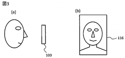
- FIG. 3 is a diagram showing a situation where the user is photographing themselves.
- the information processing apparatus 100 is arranged in front of his / her face as shown in FIG.
- the surface (front surface) side on which the display unit 116 and the second imaging unit 120 are arranged is arranged toward the user. This is because the user sees the display unit 116 functioning as a viewfinder. Therefore, shooting is performed by the second imaging unit 120.
- the video information captured by the second imaging unit 120 is displayed on the display unit 116 as shown in FIG. The user can confirm the composition photographed by the second imaging unit 120 on the display unit 116.
- the dark place mode is provided to cope with this. Details of the dark place mode will be described later.
- FIG. 4 is a flowchart showing the operation of selecting a video capture mode in the second imaging unit 120. This process starts when the user performs a menu operation or the like on the touch panel 117 and selects a process (video capturing process) to be photographed by the second imaging unit 120.
- the illuminance sensor 109 is activated to detect the illuminance of the surrounding environment of the information processing apparatus 100 (S401).
- a predetermined value S402-Yes
- video capture processing in the normal mode S403
- S402-No If the detected value by the illuminance sensor 109 is less than or equal to a predetermined value (S402-No), that is, if the ambient brightness is less than or equal to a predetermined value, an image capturing process in the dark place mode is performed (S404).
- the video capturing process in each mode will be described in detail below.
- the illuminance sensor 109 is activated when a process for imaging by the second imaging unit 120 is selected.
- a process for imaging by the second imaging unit 120 while the illuminance sensor is already activated When is selected, the process may be started from S402.
- FIG. 5 is a flowchart showing the operation of the video capturing process (FIG. 4-S403) in the normal mode.
- the second imaging unit 120 is activated (S501), and video information is captured by the second imaging unit 120 (S502).
- the video information captured by the second imaging unit 120 is displayed through on the display unit 116 (S503).
- the display unit 116 functions as a viewfinder, and the user can confirm the composition to be photographed by the second imaging unit 120.
- FIG. 6 is a diagram illustrating a display example of the display unit 116 in the normal mode. As shown in FIG. 6, the video information captured by the second imaging unit 120 is displayed through on the entire display unit 116.
- the user checks the display unit 116, adjusts the position of the information processing apparatus 100 so as to obtain a desired composition, and presses the operation button 121 that functions as a shutter button.
- the information processing apparatus 100 detects that the operation button 121 has been pressed (S504-Yes)
- the video information is captured by the second imaging unit (S505), and the image processing unit 118 performs predetermined processing.
- the video information is recorded in, for example, the storage 104 (S506), and the process is terminated.
- step S504 If it is not detected in step S504 for detecting that the operation button 121 has been pressed (S504-No), a step of capturing video information (S502) and a step of displaying the captured video information (S503) are performed. repeat. That is, until the operation button 121 is pressed, the video information captured by the second acquisition and imaging unit 120 is displayed through on the display unit 116.
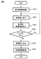
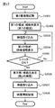
- FIG. 7 is a flowchart showing the operation of the video capturing process (FIG. 4-S404) in the dark place mode.
- the second imaging unit 120 is activated (S701), and the first region 161 of the display unit 116 is set to an auxiliary light display that displays substantially the same color (for example, white) (S702). Details of the auxiliary light display will be described later.
- the video information is captured by the second imaging unit 120 (S703), and the video information captured by the second imaging unit 120 is displayed through in the second area 162 of the display unit 116 (S704).
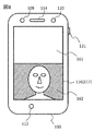
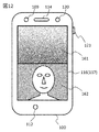
- FIG. 8 is a diagram illustrating a display example of the display unit 116 in the dark place mode.
- the display unit 116 is divided into a plurality of regions (here, two).
- the auxiliary light display of the first region 161 is to display the entire region in substantially the same color, and functions as auxiliary light.
- the auxiliary light display for example, when the display unit 116 is a device composed of R, G, and B pixels such as a liquid crystal panel, each of the R, G, and B pixels has a predetermined gradation. Make the video signal. For example, when displaying white, the gradations of R, G, and B are almost the same.
- the second area 162 functions as a finder by displaying through the video information captured by the second imaging unit 120.
- the first region for displaying auxiliary light is above the display unit and the second region for through display is below the display unit.
- the present invention is not limited to this.
- the first region is surrounded by the second region.
- the first area may be provided, or the first area may be provided above and below or right and left of the second area.
- an area for displaying auxiliary light may be appropriately adjusted so that the subject can be captured more clearly in accordance with the subject recognition result from the through image.
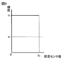
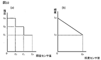
- FIG. 9 is a diagram illustrating a relationship example between the value detected by the illuminance sensor 109 and the luminance of the auxiliary light display in the first region 161 in the dark place mode.
- a predetermined value here, E 0
- the dark mode is set, and the first region 161 is displayed with auxiliary light at the luminance L 0 .
- the value of the luminance L 0 is the maximum luminance value that can be displayed on the display unit 116.
- the display unit 116 is a device such as a liquid crystal composed of R, G, and B pixels
- the gray level of each of the R, G, and B pixels is maximized.
- the information processing apparatus 100 has a function of adjusting and setting the luminance of the display unit 116. Since the brightness setting of the display unit 116 is too bright when used at the maximum, it is often set to a setting value (here, L S ) that suppresses the brightness to some extent during normal use.
- L S setting value
- auxiliary light display is performed on the first region 161 with the set value L S with reduced luminance, the amount of light that illuminates the subject may be insufficient, and clear video information may not be captured.
- the display unit 116 is set to suppress the luminance, the subject can be illuminated brightly, and the second imaging unit 120 can capture a clear image.
- the value of the illuminance sensor 109 is equal to or larger than the predetermined value E 0, since the normal mode, the luminance of the first region 161 is only E 0 below.
- the user confirms the video information displayed through in the second area 162, adjusts the position of the information processing apparatus 100 so as to obtain a desired composition, and presses the operation button 121 functioning as a shutter button.
- the information processing apparatus 100 detects that the operation button 121 is pressed (S705-Yes)
- the image information is captured by the second imaging unit (S706), and the image processing unit 118 performs predetermined processing.
- the video information is recorded in, for example, the storage 104 (S707), and the process is terminated.
- step S705 If it is not detected in step S705 that detects that the operation button 121 has been pressed (S705-No), a step of capturing video information (S703) and the captured video information are displayed in the first area 161. Step S704 is repeated. That is, until the operation button 121 is pressed, the video information captured by the second acquisition and imaging unit 120 is displayed through on the display unit 116.
- the auxiliary light display of the first region 161 functions as illumination and illuminates the subject brightly, so that the composition of the video information captured by the second imaging unit 120 can be confirmed. .
- the present invention is not limited to this.
- a plurality of set values in this case, L 0 , L 1 , and L 2
- the value of the brightness sensor 109 is set. It may be changed in stages according to the above.
- the luminance value of the first region 161 may be changed from L 3 to L 0 in accordance with the value of the luminance sensor 109.
- the luminance may be controlled according to the subject recognition result from the through image.
- the value of the luminance L 0 of the first region 161 is the maximum luminance value of the display unit 116, but the present invention is not limited to this. It is sufficient that the amount of light necessary for photographing with the second imaging unit 120 is obtained.
- FIG. 11 is a diagram showing another display example of the display unit 116 in the dark place mode.
- the example in which the areas of the first region 161 and the second region 162 are substantially equal has been described.
- the areas of the first region 161 and the second region are different. It may be allowed.
- the amount of light in the first region 161 can be increased, and brighter video information can be captured. .
- a button 122 may be displayed on the display unit 116 to serve as a shutter button. At this time, when the user touches the button 122, video information at the time of the touch is recorded in the storage 104.
- FIG. 12 is a diagram showing another display example of the display unit 116 in the dark place mode.
- FIG. 13 is a diagram illustrating the relationship between the distance from the second region 162 and the luminance of the first region 161.
- the example has been described in which the first region 161 has the same luminance, but the present invention is not limited to this.
- the brightness L 6 on the side closer to the second area is made smaller than the brightness L 0 on the side away from the second area 162.
- a luminance gradient may be provided in the long side direction of the portion 116. Since the video information displayed in the second area 162 is a video captured in a dark environment, the video information is a low-luminance video.
- the first region 161 and the second region 162 are adjacent to each other.
- a brightness gradient is provided so that the one closer to the second area 162 is darkened, the brightness difference at the boundary between the first area 161 and the second area 162 is reduced, so that a through display is displayed in the second area 162. This makes it easier to view the video information.
- the composition can be easily confirmed because the first region 161 functions as illumination for illuminating the subject.
- Each modification shown in the present embodiment may be implemented in combination as appropriate, and may be combined with other embodiments described later.
- An information processing apparatus 100 according to the second embodiment will be described. Since the internal configuration, appearance, and the like of the information processing apparatus 100 are the same as those in the first embodiment, the description thereof will be omitted as appropriate to use this. In addition, the operation of selecting a video capture mode in the second imaging unit 120 and the video capture processing in the normal mode are also the same as those in the first embodiment, and thus description thereof will be omitted as appropriate in order to use this.
- FIG. 14 is a flowchart showing the operation of the video capturing process in the dark place mode in the second embodiment.
- the second imaging unit 120 is activated (S1201), and the first area 161 of the display unit 116 is set as auxiliary light display (S1202).
- the video information is captured by the second imaging unit 120 (S1203), and the video information captured by the second imaging unit 120 is displayed through in the second area 162 of the display unit 116 (S1204).
- the user confirms the second area 162, adjusts the position of the information processing apparatus 100 so as to obtain a desired composition, and presses the operation button 121 that functions as a shutter button.
- the entire display unit 116 is set to display auxiliary light (S1206).
- the video information is captured by the second imaging unit (S1207), the image processing unit 118 performs a predetermined process, and then the video information is recorded in the storage 104 (S1208), and the process ends. If it is not detected that the operation button 121 has been pressed (S1205-No), the step of capturing video information (S1203) and the step of displaying the captured video information in the first area 161 (S1204) are repeated. . That is, until the operation button 121 is pressed, the video information captured by the second acquisition and imaging unit 120 is displayed through on the display unit 116.
- the second embodiment is different from the operation of the first embodiment in that it is detected that the operation button 121 functioning as a shutter button is pressed (S1205-Yes), and the entire display unit 116 is displayed as auxiliary light (S1206).
- the second imaging unit 120 captures video information (S1207).
- video information to be recorded in the storage 104
- there is no need to confirm the composition so there is no problem even if the entire display unit 116 is used as auxiliary light display.
- By increasing the area of the auxiliary light display when the video information is captured (S1207), the amount of light that illuminates the subject can be increased, so that clearer video information can be recorded.
- the auxiliary light display of the first region 161 functions as illumination and illuminates the subject brightly, so that the composition of the video information captured by the second imaging unit 120 can be confirmed. . Further, when capturing the video information to be recorded in the storage 104, clearer video information can be recorded by making the entire display unit 116 an auxiliary light display.
- An information processing apparatus 100 according to the third embodiment will be described. Since the internal configuration, appearance, and the like of the information processing apparatus 100 are the same as those in the first embodiment, the description thereof will be omitted as appropriate by using this. In addition, the operation of selecting a video capture mode in the second imaging unit 120 and the video capture process in the normal mode are also the same as those in the first and second embodiments, so that the description thereof will be omitted as appropriate. .
- FIG. 15 is a flowchart illustrating the operation of the image capturing process in the dark place mode according to the third embodiment. It activates the second imaging section 120 (S1301), the auxiliary light displaying a first region 161 of the display unit 116 in the first luminance L 4 (S1302). Next, the video information is captured by the second imaging unit 120 (S1303), and the video information captured by the second imaging unit 120 is displayed through in the second area 162 of the display unit 116 (S1304). The user confirms the second area 162, adjusts the position of the information processing apparatus 100 so as to obtain a desired composition, and presses the operation button 121 that functions as a shutter button.
- the information processing apparatus 100 detects that the operation button 121 is pressed (S1305-Yes), the auxiliary light displaying a first region 161 of the display unit 116 at the second luminance L 5 (S1306).
- the video information is captured by the second imaging unit (S1307), and after predetermined processing is performed by the image processing unit 118, the video information is recorded in the storage 104 (S1308), and the processing is terminated. If it is not detected that the operation button 121 has been pressed (No in S1305), the step of capturing video information (S1303) and the step of displaying the captured video information in the first area 161 (S1304) are repeated. . That is, until the operation button 121 is pressed, the video information captured by the second acquisition and imaging unit 120 is displayed through on the display unit 116.
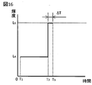
- FIG. 16 is a diagram showing the relationship between the time since the start of this process and the luminance of the first region 161.
- Time T 1 is the time step of the auxiliary light display (S1302) is performed a first region 161 in the first luminance L 4.
- Time T 2 are a time step of the auxiliary light display (S1306) is performed a first region 161 at a second luminance L 5.
- Time T 3 is the time you have finished this process.
- the second luminance L 5 corresponds to the luminance L 0 of the first embodiment and is the maximum value of the luminance of the display unit 116.
- the first luminance L 4 is set to a smaller value than the second luminance L 5 .
- the luminance of the first area 161 is the first luminance L 4, and during the time T 1 to T 2 , the second imaging unit 120 uses the video information displayed through the second area 162 by the user. This is the time when the process of confirming the composition of the captured video information is being performed. At this time, since only composition is confirmed, there is no particular problem even if the video information is somewhat dark.
- the luminance of the first region 161 is a second luminance L 5. Therefore, when capturing video information to be recorded in the storage 104, the luminance of the first area 161 is high, so that the subject can be illuminated brightly, and clear video information can be recorded as in the first embodiment.
- the auxiliary light display of the first region 161 functions as illumination and illuminates the subject brightly, so that the composition of the video information captured by the second imaging unit 120 can be confirmed. .
- the brightness of the first area 161 can be lowered to reduce glare to the user, and the time to shine at the brightness L 5 can be reduced to reduce the first area 161.
- An increase in power consumption due to the auxiliary light display can be suppressed.
- An information processing apparatus 100 according to the fourth embodiment will be described. Since the internal configuration, appearance, and the like of the information processing apparatus 100 are the same as those in the first embodiment, the description thereof will be omitted as appropriate by using this. In addition, the operation of selecting a video capture mode in the second imaging unit 120 and the video capture processing in the normal mode are also the same as those in the first to third embodiments. .
- FIG. 17 is a flowchart illustrating the operation of the image capturing process in the dark place mode according to the fourth embodiment. It activates the second imaging section 120 (S1501), the auxiliary light displaying a first region 161 of the display unit 116 in the first luminance L 4 (S1502). Next, the video information is captured by the second imaging unit 120 (S1503), and the video information captured by the second imaging unit 120 is displayed through in the second area 162 of the display unit 116 (S1504). The user confirms the second area 162, adjusts the position of the information processing apparatus 100 so as to obtain a desired composition, and presses the operation button 121 that functions as a shutter button.
- the information processing apparatus 100 detects that the operation button 121 is pressed (S1505-Yes), the auxiliary light display the entire display unit 116 at the second luminance L 5 (S1506).
- the video information is taken in by the second imaging unit (S1507), and after predetermined processing is performed by the image processing unit 118, the video information is recorded in the storage 104 (S1508), and the processing is terminated.
- the step of capturing video information (S1503) and the step of displaying the captured video information in the first area 161 (S1504) are repeated. . That is, until the operation button 121 is pressed, the video information captured by the second acquisition and imaging unit 120 is displayed through on the display unit 116.
- the difference from the operation of the third embodiment is that when it is detected that the operation button 121 which is a shutter button is pressed (S1505-Yes), the entire display unit 116 is set as an auxiliary light display (S1506), and the second imaging unit 120 is operated.
- the video information is taken in at (S1507).
- the video information is captured by increasing the area of the auxiliary light display (S1507), the amount of light that illuminates the subject can be increased, so that clearer video information can be recorded.
- the auxiliary light display of the first region 161 functions as illumination and illuminates the subject brightly, so that the composition of the video information captured by the second imaging unit 120 can be confirmed. .
- the brightness of the first area 161 can be lowered to reduce glare to the user, and the time to shine at the brightness L 5 can be reduced to reduce the first area 161.
- An increase in power consumption due to the auxiliary light display can be suppressed.
- the entire display unit 116 is set as auxiliary light display, so that the amount of illumination for illuminating the subject can be increased, so that clearer video information is recorded. be able to.
- An information processing apparatus 100 according to the fifth embodiment will be described. Since the internal configuration, appearance, and the like of the information processing apparatus 100 are the same as those in the first embodiment, the description thereof will be omitted as appropriate by using this. In addition, the operation of selecting a video capture mode in the second imaging unit 120 and the video capture processing in the normal mode are also the same as those in the first to fourth embodiments, and thus the description thereof will be omitted as appropriate. .
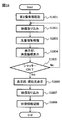
- FIG. 18 is a flowchart showing the operation of the video capturing process in the dark place mode in the fifth embodiment.
- the second imaging unit 120 is activated (S1801), and video information is captured by the second imaging unit 120 (S1802).
- a light amount increase process of the video information captured by the image processing unit 118 is performed (S1803) and displayed on the display unit 116 (S1804).
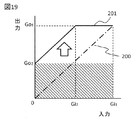
- the light amount increasing process is a process for increasing the total light amount emitted from the display unit 116.
- FIG. 19 is a diagram illustrating an example of the light quantity increase processing characteristic.
- the video information displayed on the display unit 116 is displayed with the luminance of each pixel being increased, so that the amount of emitted light is increased and functions as illumination for illuminating the subject.
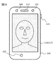
- FIG. 20 is a diagram illustrating a state of the display unit 116 in the above-described displaying step (S1804). As shown in the figure, the light quantity increasing process is performed on the video information captured from the second imaging unit 120 and displayed on the entire display unit 116. Since the brightness and color differ for each pixel in the area of the display unit 116, the illumination for illuminating the subject is uneven, but here, there is no particular influence because only the composition (position of the subject) is confirmed.
- the user confirms the display unit 116, adjusts the position of the information processing apparatus 100 so as to obtain a desired composition, and presses the operation button 121 which is a shutter button.
- the display unit 116 sets the auxiliary light display (S1806), and the second imaging unit captures video information (S1807).
- the captured video information is subjected to a predetermined process by the image processing unit 118, and then recorded in the storage 104 (S1808), and the process ends.
- the entire display unit 116 is set to the auxiliary light display. Therefore, the subject can be illuminated with uniform illumination, and clear video information can be recorded.
- the process returns to the step of taking video information (S1802). That is, until the operation button 121 is pressed, the light amount increasing process of the video information captured by the second image capturing unit 120 is performed, and the process of displaying on the display unit 116 is repeated.
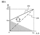
- FIG. 21 is a diagram showing another example of the light quantity increase processing characteristic.
- the shift is performed so that it is uniformly increased by Go 2 from the low range to the high range.
- the shift amount is decreased as the frequency goes to the high range. .
- the light quantity increase amount is reduced, but since there are many gradations that can be expressed, there is an advantage that it is easy to visually recognize.
- the shift amount of the light amount increasing process may be changed according to the detection value by the illuminance sensor 109.
- the operation of the present embodiment is different from the operations of Embodiments 1 to 4 in that the video information subjected to the light amount increase process is displayed on the display unit 116.
- the display unit 116 functions as illumination for illuminating the subject, the composition can be easily confirmed.
- the operation button 121 is pressed, the entire display unit 116 is set as auxiliary light display, and video information is captured by the second imaging unit 120.
- the video information is captured in a state where the entire display unit 116 is used as auxiliary light display and the subject is illuminated with uniform illumination, so that clear video information can be recorded.
- the present invention is not limited to this. Any mode can be applied as long as it is a mode in which the imaging unit (here, the second imaging unit 120) arranged on the surface side on which the display unit 116 is mounted.
- the present invention can be applied to a mode for photographing a face when the key lock function is canceled by face authentication.
- the luminance at the time of auxiliary light display and the shift amount of the light amount increasing process are gradually increased, and when the video information captured by the second imaging unit 120 has a predetermined brightness, it is stored in the storage 104. Recording or face authentication may be performed.
- a smartphone has been described as an example.
- the present invention is not limited to this.
- the present invention may be used for a tablet, a laptop computer, a desktop computer, or the like.
- a plurality of operation flows in the dark place mode are shown, but the operation in the dark place mode in the information processing apparatus is not limited to any one of these, and corresponds to each operation flow.
- a plurality of dark place modes may be provided so that the user can set any dark place mode in advance.
- this invention is not limited to an above-described Example, Various modifications are included.
- the above-described embodiments have been described in detail for easy understanding of the present invention, and are not necessarily limited to those having all the configurations described.
- Each of the above-described configurations, functions, processing units, processing means, and the like may be realized by hardware by designing a part or all of them with, for example, an integrated circuit.
- Each of the above-described configurations, functions, and the like may be realized by software by interpreting and executing a program that realizes each function by the processor.
- control lines and information lines indicate what is considered necessary for the explanation, and not all the control lines and information lines on the product are necessarily shown. Actually, it may be considered that almost all the components are connected to each other.
- Information processing device 109 Illuminance sensor 116 Display unit 119 First imaging unit 120 Second imaging unit 161 First area 162 Second area
Landscapes
- Engineering & Computer Science (AREA)
- Multimedia (AREA)
- Signal Processing (AREA)
- Human Computer Interaction (AREA)
- Studio Devices (AREA)
Abstract
Description
(1)情報処理装置であって、撮像部と、表示部と、照度センサと、を備え、前記撮像部と前記表示部とは、前記情報処理装置の第一の面側に配置されており、前記照度センサの検出値が所定値以下で前記撮像部により撮像する場合に、前記表示部の少なくとも一部を補助光として用いるモードを備えることを特徴とする情報処理装置である。
(2)(1)記載の情報処理装置であって、前記照度センサの検出値が所定値以下で前記撮像部により撮像する場合に、前記表示部の第一の領域には前記撮像部により取り込んだ映像情報を表示し、前記表示部の第二の領域には前記映像情報とは異なる映像情報を前記第一の領域よりも高い輝度で表示することを特徴とする情報処理装置である。
(3)撮像部と、表示部と、照度センサと、を備えた情報処理装置を用いた情報処理方法であって、前記照度センサにより照度を検出するステップと、前記照度センサの検出値が所定値以下で前記撮像部により撮像する場合に、前記表示部の少なくとも一部を補助光として用いるモードに設定するステップと、を有することを特徴とする情報処理方法である。
(4)撮像部と、表示部と、照度センサと、を備えた情報処理装置に、前記照度センサの検出値が所定値以下で前記撮像部により撮像する場合に、前記表示部の少なくとも一部を補助光として用いるモードに設定するステップを実行させるためのプログラムである。
ここでは、スマートフォンの場合を例にして説明する。情報処理装置100は、基地局通信部101、CPU102、メモリ103、ストレージ104、GPS(Global Positioning System)受信部105、地磁気センサ106、加速度センサ107、ジャイロセンサ108、照度センサ109、入出力I/F110、無線通信部111、マイク112、音声処理部113、スピーカ114、操作入力部115、表示部116、タッチパネル117、画像処理部118、第1撮像部119、第2撮像部120、操作ボタン121を適宜用いて構成され、それぞれはバス150を介して相互に接続されている。
図2に示すように、情報処理装置100の正面側に、照度センサ109、マイク112、スピーカ114、タッチパネル117、第2撮像部120が配置されている。また、情報処理装置100の背面側には、第1撮像部119が配置され、情報処理装置100の側面に操作ボタン121が配置されている。第1撮像部119は、情報処理装置100の背面側の映像を撮影するものであり、第2撮像部120は正面側の映像を撮影するものである。撮影する場合は、第1撮像部119あるいは第2撮像部120により取り込まれる映像情報を表示部116に表示されるようになっており、表示部116をファインダーとして使用することができる。以降、取り込まれた映像情報をそのまま表示することをスルー表示という。
第2撮像部120を起動させ(S501)、第2撮像部120による映像情報の取り込みを行う(S502)。第2撮像部120にて取り込んだ映像情報を表示部116にスルー表示させる(S503)。これにより、表示部116がファインダーとして機能し、ユーザーは、第2撮像部120で撮影する構図を確認することができる。図6は、通常モード時における表示部116の表示例を示した図である。図6に示すように、表示部116全体に第2撮像部120にて取り込んでいる映像情報をスルー表示している。ユーザーは、表示部116を確認し、所望の構図になるように情報処理装置100の位置を調整し、シャッターボタンとして機能する操作ボタン121を押す。情報処理装置100は、操作ボタン121が押されたことを検出すると(S504-Yes)、第2撮像部にて映像情報を取り込み(S505)、画像処理部118にて所定の処理を行った後に、映像情報を例えばストレージ104に記録し(S506)、処理を終了する。
第2撮像部120を起動させ(S701)、表示部116の第1の領域161を略同一色(例えば白色など)で表示する補助光表示とする(S702)。補助光表示の詳細については、後述する。次に、第2撮像部120にて映像情報の取り込みを行い(S703)、第2撮像部120にて取り込んだ映像情報を表示部116の第2の領域162にスルー表示させる(S704)。
尚、本実施例で示した各変形例は適宜組み合わせて実施するようにしてもよく、後述する他の実施例と組み合わせても構わない。
情報処理装置100の内部構成、外観などは、上記実施例1と同等であるため、これを援用するものとして適宜説明は省略する。また、第2撮像部120における映像取り込みのモード選択の動作、通常モード時における映像取り込み処理についても実施例1と同等であるため、これを援用するものとして適宜説明は省略する。
情報処理装置100の内部構成、外観などは、上記実施例1と同等であるため、これを援用するものとして、適宜説明は省略する。また、第2撮像部120における映像取り込みのモード選択の動作、通常モード時における映像取り込み処理についても実施例1、実施例2と同等であるため、これを援用するものとして、適宜説明は省略する。
情報処理装置100の内部構成、外観などは、上記実施例1と同等であるため、これを援用するものとして、適宜説明は省略する。また、第2撮像部120における映像取り込みのモード選択の動作、通常モード時における映像取り込み処理についても実施例1乃至実施例3と同等であるため、これを援用するものとして、適宜説明は省略する。
情報処理装置100の内部構成、外観などは、上記実施例1と同等であるため、これを援用するものとして、適宜説明は省略する。また、第2撮像部120における映像取り込みのモード選択の動作、通常モード時における映像取り込み処理についても実施例1乃至実施例4と同等であるため、これを援用するものとして、適宜説明は省略する。
また、上記の各構成、機能、処理部、処理手段等は、それらの一部又は全部を、例えば集積回路で設計する等によりハードウェアで実現してもよい。また、上記の各構成、機能等は、プロセッサがそれぞれの機能を実現するプログラムを解釈し、実行することによりソフトウェアで実現してもよい。各機能を実現するプログラム、テーブル、ファイル等の情報は、フラッシュメモリなどのメモリ、または、メモリーカードなどのストレージに置くことができる。
また、制御線や情報線は説明上必要と考えられるものを示しており、製品上必ずしも全ての制御線や情報線を示しているとは限らない。実際には殆ど全ての構成が相互に接続されていると考えてもよい。
109 照度センサ
116 表示部
119 第1撮像部
120 第2撮像部
161 第1の領域
162 第2の領域
Claims (12)
- 情報処理装置であって、
撮像部と、表示部と、照度センサと、を備え、
前記撮像部と前記表示部とは、前記情報処理装置の第一の面側に配置されており、
前記照度センサの検出値が所定値以下で前記撮像部により撮像する場合に、前記表示部の少なくとも一部を補助光として用いるモードを備えることを特徴とする情報処理装置。 - 請求項1記載の情報処理装置であって、
前記照度センサの検出値が所定値以下で前記撮像部により撮像する場合に、
前記表示部の第一の領域には前記撮像部により取り込んだ映像情報を表示し、
前記表示部の第二の領域には前記映像情報とは異なる映像情報を前記第一の領域よりも高い輝度で表示することを特徴とする情報処理装置。 - 請求項2記載の情報処理装置であって、
前記表示部の第二の領域のうち、前記第一の領域に近い領域の輝度が、前記第一の領域より遠い領域の輝度よりも低いことを特徴とする情報処理装置。 - 請求項2記載の情報処理装置であって、
前記表示部の第二の領域内は略同一の輝度であることを特徴とする情報処理装置。 - 請求項2乃至4のいずれかに記載の情報処理装置であって、
前記表示部の第二の領域の輝度は、前記照度センサの検出値に応じて変化することを特徴とする情報処理装置。 - 請求項2乃至5のいずれかに記載の情報処理装置であって、
前記表示部の第二の領域は前記第一の領域の上下又は左右にあることを特徴とする情報処理装置。 - 請求項1記載の情報処理装置であって、
前記表示部は、
前記撮像部により取り込まれた映像情報に対して光量増加処理を施した映像情報をスルー表示し、
前記スルー表示した状態で、前記撮像部により取り込まれた映像情報を記録するようにユーザからの指示を受け付けた場合には、補助光表示として前記映像情報よりも高い輝度の表示に切り替わることを特徴とする情報処理装置。 - 請求項1乃至6のいずれかに記載の情報処理装置であって、
前記撮像部より取り込んだ映像情報に人物の顔が含まれていることを検出すると、
取り込んだ映像情報を用いて顔認証処理を行うことを特徴とする情報処理装置。 - 撮像部と、表示部と、照度センサと、を備えた情報処理装置を用いた情報処理方法であって、
前記照度センサにより照度を検出するステップと、
前記照度センサの検出値が所定値以下で前記撮像部により撮像する場合に、前記表示部の少なくとも一部を補助光として用いるモードに設定するステップと、
を有することを特徴とする情報処理方法。 - 請求項9記載の情報処理方法であって、
前記モードが設定されると、前記表示部の第一の領域には前記撮像部により取り込んだ映像情報を表示し、前記表示部の第二の領域には前記映像情報とは異なる映像情報を前記第一の領域よりも高い輝度で表示するステップと、
を有することを特徴とする情報処理方法。 - 請求項9記載の情報処理方法であって、
前記モードが設定されると、前記表示部は、前記撮像部により取り込まれた映像情報に対して光量増加処理を施した映像情報をスルー表示し、前記スルー表示した状態で、前記撮像部により取り込まれた映像情報を記録するようにユーザからの指示を受け付けた場合には、補助光表示として前記映像情報よりも高い輝度の表示に切り替わるステップと、
を有することを特徴とする情報処理方法。 - 撮像部と、表示部と、照度センサと、を備えた情報処理装置に、
前記照度センサの検出値が所定値以下で前記撮像部により撮像する場合に、前記表示部の少なくとも一部を補助光として用いるモードに設定するステップを実行させるためのプログラム。
Priority Applications (4)
| Application Number | Priority Date | Filing Date | Title |
|---|---|---|---|
| PCT/JP2013/073241 WO2015029199A1 (ja) | 2013-08-30 | 2013-08-30 | 情報処理装置、情報処理方法、及び、プログラム |
| JP2015533877A JP6270854B2 (ja) | 2013-08-30 | 2013-08-30 | 情報処理装置、情報処理方法、及び、プログラム |
| US14/914,738 US9942483B2 (en) | 2013-08-30 | 2013-08-30 | Information processing device and method using display for auxiliary light |
| CN201380079223.5A CN105493494B (zh) | 2013-08-30 | 2013-08-30 | 信息处理装置、信息处理方法和存储介质 |
Applications Claiming Priority (1)
| Application Number | Priority Date | Filing Date | Title |
|---|---|---|---|
| PCT/JP2013/073241 WO2015029199A1 (ja) | 2013-08-30 | 2013-08-30 | 情報処理装置、情報処理方法、及び、プログラム |
Publications (1)
| Publication Number | Publication Date |
|---|---|
| WO2015029199A1 true WO2015029199A1 (ja) | 2015-03-05 |
Family
ID=52585815
Family Applications (1)
| Application Number | Title | Priority Date | Filing Date |
|---|---|---|---|
| PCT/JP2013/073241 Ceased WO2015029199A1 (ja) | 2013-08-30 | 2013-08-30 | 情報処理装置、情報処理方法、及び、プログラム |
Country Status (4)
| Country | Link |
|---|---|
| US (1) | US9942483B2 (ja) |
| JP (1) | JP6270854B2 (ja) |
| CN (1) | CN105493494B (ja) |
| WO (1) | WO2015029199A1 (ja) |
Families Citing this family (9)
| Publication number | Priority date | Publication date | Assignee | Title |
|---|---|---|---|---|
| WO2014188895A1 (en) | 2013-05-21 | 2014-11-27 | Semiconductor Energy Laboratory Co., Ltd. | Light-emitting device and camera |
| KR102810509B1 (ko) * | 2013-11-28 | 2025-05-22 | 가부시키가이샤 한도오따이 에네루기 켄큐쇼 | 전자 기기 및 그 구동 방법 |
| US20150163410A1 (en) * | 2013-12-10 | 2015-06-11 | Semiconductor Energy Laboratory Co., Ltd. | Display Device and Electronic Device |
| KR102358935B1 (ko) * | 2014-02-12 | 2022-02-04 | 가부시키가이샤 한도오따이 에네루기 켄큐쇼 | 전자 기기 |
| US20170134625A1 (en) * | 2015-11-09 | 2017-05-11 | Qualcomm Incorporated | Dedicated illumination element and display based flash illumination for image capture |
| US9762807B1 (en) * | 2016-03-10 | 2017-09-12 | Intel Corporation | Using display light to improve front facing camera performance |
| KR102710756B1 (ko) * | 2016-08-29 | 2024-09-27 | 삼성전자주식회사 | 조도를 측정하는 방법 및 그 전자 장치 |
| CN107222664B (zh) * | 2017-05-03 | 2020-03-06 | Oppo广东移动通信有限公司 | 相机模组及电子装置 |
| US11755905B2 (en) | 2018-06-22 | 2023-09-12 | Semiconductor Energy Laboratory Co., Ltd. | Data processing method, image display method, data processing device, and image display device |
Citations (5)
| Publication number | Priority date | Publication date | Assignee | Title |
|---|---|---|---|---|
| JP2004180245A (ja) * | 2002-11-29 | 2004-06-24 | Casio Comput Co Ltd | 携帯端末機器、撮像装置、撮像方法及びプログラム |
| JP2004187154A (ja) * | 2002-12-05 | 2004-07-02 | Sharp Corp | カメラ搭載携帯端末 |
| JP2004214798A (ja) * | 2002-12-27 | 2004-07-29 | Casio Comput Co Ltd | 撮像機能付き携帯電子機器 |
| JP2008107942A (ja) * | 2006-10-24 | 2008-05-08 | Omron Corp | なりすまし検知装置 |
| JP2011109483A (ja) * | 2009-11-18 | 2011-06-02 | Fujitsu Ltd | 携帯端末および輝度調整プログラム |
Family Cites Families (18)
| Publication number | Priority date | Publication date | Assignee | Title |
|---|---|---|---|---|
| JP2005286440A (ja) | 2004-03-29 | 2005-10-13 | Fuji Photo Film Co Ltd | カメラ付情報端末 |
| JP2006024193A (ja) * | 2004-06-07 | 2006-01-26 | Fuji Photo Film Co Ltd | 画像補正装置、画像補正プログラム、画像補正方法、および画像補正システム |
| JP2006050337A (ja) * | 2004-08-05 | 2006-02-16 | Sony Corp | 撮像装置、撮像方法および撮像制御プログラム |
| JP2006119264A (ja) * | 2004-10-20 | 2006-05-11 | Fuji Photo Film Co Ltd | 撮影装置 |
| US7663691B2 (en) * | 2005-10-11 | 2010-02-16 | Apple Inc. | Image capture using display device as light source |
| US20090115880A1 (en) * | 2007-11-02 | 2009-05-07 | Canon Kabushiki Kaisha | Image pickup apparatus and display controlling method therefor |
| US20090160945A1 (en) * | 2007-12-21 | 2009-06-25 | Dell Products L.P. | Systems and Methods for Enhancing Image Quality of a Web Camera Image |
| US8922672B2 (en) * | 2008-01-03 | 2014-12-30 | Apple Inc. | Illumination systems and methods for imagers |
| JP2009177272A (ja) * | 2008-01-22 | 2009-08-06 | Sony Corp | 撮像装置、その制御方法およびプログラム |
| US7903143B2 (en) * | 2008-03-13 | 2011-03-08 | Dell Products L.P. | Systems and methods for document scanning using a variable intensity display of an information handling system |
| US8446450B2 (en) * | 2008-04-30 | 2013-05-21 | Cisco Technology, Inc. | Method of lighting |
| US20090322889A1 (en) * | 2008-06-27 | 2009-12-31 | Motorola, Inc. | Method and apparatus for illuminating users of video communication devices |
| US8797441B2 (en) * | 2009-01-30 | 2014-08-05 | Apple Inc. | Continuous illumination of backlit display and of subject for image capture |
| JP5493512B2 (ja) * | 2009-07-02 | 2014-05-14 | パナソニック株式会社 | 撮像装置、及びこれを搭載した携帯電話機 |
| US8605205B2 (en) * | 2011-08-15 | 2013-12-10 | Microsoft Corporation | Display as lighting for photos or video |
| CN103152523A (zh) * | 2013-02-27 | 2013-06-12 | 华为终端有限公司 | 电子设备拍摄方法及装置和电子设备 |
| JP5751270B2 (ja) * | 2013-03-21 | 2015-07-22 | カシオ計算機株式会社 | 撮像装置、撮像制御方法及びプログラム |
| US9525811B2 (en) * | 2013-07-01 | 2016-12-20 | Qualcomm Incorporated | Display device configured as an illumination source |
-
2013
- 2013-08-30 CN CN201380079223.5A patent/CN105493494B/zh active Active
- 2013-08-30 JP JP2015533877A patent/JP6270854B2/ja active Active
- 2013-08-30 WO PCT/JP2013/073241 patent/WO2015029199A1/ja not_active Ceased
- 2013-08-30 US US14/914,738 patent/US9942483B2/en active Active
Patent Citations (5)
| Publication number | Priority date | Publication date | Assignee | Title |
|---|---|---|---|---|
| JP2004180245A (ja) * | 2002-11-29 | 2004-06-24 | Casio Comput Co Ltd | 携帯端末機器、撮像装置、撮像方法及びプログラム |
| JP2004187154A (ja) * | 2002-12-05 | 2004-07-02 | Sharp Corp | カメラ搭載携帯端末 |
| JP2004214798A (ja) * | 2002-12-27 | 2004-07-29 | Casio Comput Co Ltd | 撮像機能付き携帯電子機器 |
| JP2008107942A (ja) * | 2006-10-24 | 2008-05-08 | Omron Corp | なりすまし検知装置 |
| JP2011109483A (ja) * | 2009-11-18 | 2011-06-02 | Fujitsu Ltd | 携帯端末および輝度調整プログラム |
Also Published As
| Publication number | Publication date |
|---|---|
| JP6270854B2 (ja) | 2018-01-31 |
| CN105493494B (zh) | 2019-08-06 |
| JPWO2015029199A1 (ja) | 2017-03-02 |
| CN105493494A (zh) | 2016-04-13 |
| US20160212318A1 (en) | 2016-07-21 |
| US9942483B2 (en) | 2018-04-10 |
Similar Documents
| Publication | Publication Date | Title |
|---|---|---|
| JP6270854B2 (ja) | 情報処理装置、情報処理方法、及び、プログラム | |
| US11070743B2 (en) | Photographing using night shot mode processing and user interface | |
| EP2770724B1 (en) | Apparatus and method for positioning image area using image sensor location | |
| US9148587B2 (en) | Image processing device, imaging device, image processing method, and non-transitory computer readable medium | |
| JP6272486B2 (ja) | 画像処理装置、撮像装置、画像処理方法、及びプログラム | |
| US20150026632A1 (en) | Portable electronic device and display control method | |
| US10205868B2 (en) | Live view control device, live view control method, live view system, and program | |
| US11032483B2 (en) | Imaging apparatus, imaging method, and program | |
| KR20140106265A (ko) | 이미지 촬영장치 및 방법 | |
| JP4450783B2 (ja) | 撮影装置 | |
| JP5730439B2 (ja) | 画像表示装置、撮影装置、画像表示システム及び方法 | |
| JP6374535B2 (ja) | 操作装置、追尾システム、操作方法、及びプログラム | |
| JPWO2020066317A1 (ja) | 撮影装置、撮影方法、及びプログラム | |
| JPWO2016035422A1 (ja) | 撮像装置の操作装置、操作方法、及びプログラム | |
| KR20150078752A (ko) | 와이파이 다이렉트 기반의 촬영 방법 및 이를 수행하는 전자 장치 | |
| CN111355879B (zh) | 包含特效图案的图像获取方法、装置和电子设备 | |
| WO2013136602A1 (ja) | プロジェクタ付き撮影装置及びその撮影制御方法 | |
| KR102241840B1 (ko) | 이미지 촬영장치 및 방법 | |
| US9524702B2 (en) | Display control device, display control method, and recording medium | |
| WO2020209097A1 (ja) | 画像表示装置、画像表示方法、及びプログラム | |
| JP7764560B2 (ja) | 撮像装置、撮像方法、及びプログラム | |
| JPWO2020066332A1 (ja) | 撮影装置、撮影方法、及びプログラム | |
| JPWO2020174911A1 (ja) | 画像表示装置、画像表示方法、及びプログラム | |
| WO2020003944A1 (ja) | 撮像装置、撮像方法、及びプログラム | |
| KR20140089134A (ko) | 듀얼 카메라를 구비하는 장치의 이미지 처리 장치 및 방법 |
Legal Events
| Date | Code | Title | Description |
|---|---|---|---|
| WWE | Wipo information: entry into national phase |
Ref document number: 201380079223.5 Country of ref document: CN |
|
| 121 | Ep: the epo has been informed by wipo that ep was designated in this application |
Ref document number: 13892627 Country of ref document: EP Kind code of ref document: A1 |
|
| ENP | Entry into the national phase |
Ref document number: 2015533877 Country of ref document: JP Kind code of ref document: A |
|
| WWE | Wipo information: entry into national phase |
Ref document number: 14914738 Country of ref document: US |
|
| NENP | Non-entry into the national phase |
Ref country code: DE |
|
| 122 | Ep: pct application non-entry in european phase |
Ref document number: 13892627 Country of ref document: EP Kind code of ref document: A1 |