WO2015029166A1 - 内燃機関の制御装置 - Google Patents
内燃機関の制御装置 Download PDFInfo
- Publication number
- WO2015029166A1 WO2015029166A1 PCT/JP2013/073036 JP2013073036W WO2015029166A1 WO 2015029166 A1 WO2015029166 A1 WO 2015029166A1 JP 2013073036 W JP2013073036 W JP 2013073036W WO 2015029166 A1 WO2015029166 A1 WO 2015029166A1
- Authority
- WO
- WIPO (PCT)
- Prior art keywords
- air
- fuel ratio
- control
- ratio sensor
- fuel
- Prior art date
- Legal status (The legal status is an assumption and is not a legal conclusion. Google has not performed a legal analysis and makes no representation as to the accuracy of the status listed.)
- Ceased
Links
Images






Classifications
-
- F—MECHANICAL ENGINEERING; LIGHTING; HEATING; WEAPONS; BLASTING
- F02—COMBUSTION ENGINES; HOT-GAS OR COMBUSTION-PRODUCT ENGINE PLANTS
- F02D—CONTROLLING COMBUSTION ENGINES
- F02D41/00—Electrical control of supply of combustible mixture or its constituents
- F02D41/02—Circuit arrangements for generating control signals
- F02D41/14—Introducing closed-loop corrections
- F02D41/1438—Introducing closed-loop corrections using means for determining characteristics of the combustion gases; Sensors therefor
- F02D41/1493—Details
- F02D41/1495—Detection of abnormalities in the air/fuel ratio feedback system
-
- F—MECHANICAL ENGINEERING; LIGHTING; HEATING; WEAPONS; BLASTING
- F02—COMBUSTION ENGINES; HOT-GAS OR COMBUSTION-PRODUCT ENGINE PLANTS
- F02D—CONTROLLING COMBUSTION ENGINES
- F02D41/00—Electrical control of supply of combustible mixture or its constituents
- F02D41/02—Circuit arrangements for generating control signals
- F02D41/04—Introducing corrections for particular operating conditions
- F02D41/12—Introducing corrections for particular operating conditions for deceleration
- F02D41/123—Introducing corrections for particular operating conditions for deceleration the fuel injection being cut-off
-
- G—PHYSICS
- G01—MEASURING; TESTING
- G01N—INVESTIGATING OR ANALYSING MATERIALS BY DETERMINING THEIR CHEMICAL OR PHYSICAL PROPERTIES
- G01N27/00—Investigating or analysing materials by the use of electric, electrochemical, or magnetic means
- G01N27/26—Investigating or analysing materials by the use of electric, electrochemical, or magnetic means by investigating electrochemical variables; by using electrolysis or electrophoresis
- G01N27/403—Cells and electrode assemblies
- G01N27/406—Cells and probes with solid electrolytes
- G01N27/4065—Circuit arrangements specially adapted therefor
-
- F—MECHANICAL ENGINEERING; LIGHTING; HEATING; WEAPONS; BLASTING
- F02—COMBUSTION ENGINES; HOT-GAS OR COMBUSTION-PRODUCT ENGINE PLANTS
- F02D—CONTROLLING COMBUSTION ENGINES
- F02D41/00—Electrical control of supply of combustible mixture or its constituents
- F02D41/02—Circuit arrangements for generating control signals
- F02D41/04—Introducing corrections for particular operating conditions
- F02D41/12—Introducing corrections for particular operating conditions for deceleration
- F02D41/123—Introducing corrections for particular operating conditions for deceleration the fuel injection being cut-off
- F02D41/126—Introducing corrections for particular operating conditions for deceleration the fuel injection being cut-off transitional corrections at the end of the cut-off period
-
- F—MECHANICAL ENGINEERING; LIGHTING; HEATING; WEAPONS; BLASTING
- F02—COMBUSTION ENGINES; HOT-GAS OR COMBUSTION-PRODUCT ENGINE PLANTS
- F02D—CONTROLLING COMBUSTION ENGINES
- F02D41/00—Electrical control of supply of combustible mixture or its constituents
- F02D41/02—Circuit arrangements for generating control signals
- F02D41/14—Introducing closed-loop corrections
- F02D41/1438—Introducing closed-loop corrections using means for determining characteristics of the combustion gases; Sensors therefor
- F02D41/1444—Introducing closed-loop corrections using means for determining characteristics of the combustion gases; Sensors therefor characterised by the characteristics of the combustion gases
- F02D41/1454—Introducing closed-loop corrections using means for determining characteristics of the combustion gases; Sensors therefor characterised by the characteristics of the combustion gases the characteristics being an oxygen content or concentration or the air-fuel ratio
- F02D41/1456—Introducing closed-loop corrections using means for determining characteristics of the combustion gases; Sensors therefor characterised by the characteristics of the combustion gases the characteristics being an oxygen content or concentration or the air-fuel ratio with sensor output signal being linear or quasi-linear with the concentration of oxygen
Definitions
- the present invention relates to a control device for an internal combustion engine.
- Such an air-fuel ratio sensor includes a first electrode exposed to exhaust gas flowing in the exhaust passage, a second electrode exposed to the atmosphere, zirconia disposed between the first electrode and the second electrode, etc.
- a sensor having a solid electrolyte layer is used.
- exhaust air-fuel ratio air-fuel ratio of the exhaust gas
- a constant voltage for example, 0.45 V
- a current is detected as an output current.
- the exhaust air / fuel ratio is calculated based on this output current.
- Patent Document 1 it has been proposed to limit the applied voltage in the air-fuel ratio sensor during execution of fuel cut control (for example, Patent Document 1). According to Patent Document 1, when the applied voltage is limited in this way, the output current becomes small even during execution of the fuel cut control, and it is possible to prevent an excessive output current from being generated. .
- the air-fuel ratio sensor used in such an internal combustion engine gradually deteriorates with use.
- Examples of such deterioration include responsiveness deterioration in which a change in the output current of the air-fuel ratio sensor is delayed with respect to an actual change in the air-fuel ratio.
- various controls executed by the control device for the internal combustion engine will be hindered.
- abnormality diagnosis control for diagnosing deterioration of the air-fuel ratio sensor as abnormality.
- a response time required for the output value of the air-fuel ratio sensor to change accordingly is detected, and the abnormality diagnosis of the air-fuel ratio sensor is performed based on the response time. Is done.
- the greater the degree to which the actual air-fuel ratio is changed the more accurately the diagnosis can be made.
- the applied voltage in the air-fuel ratio sensor is changed greatly, noise is temporarily generated in the air-fuel ratio sensor.
- the applied voltage is reduced to, for example, 0 V during the execution of the fuel cut control, and the applied voltage is set to the normal voltage (the voltage applied when the fuel cut control is not being performed) when the fuel cut control is completed.
- the voltage is suddenly changed to 0.45 V
- noise is generated in the output current of the air-fuel ratio sensor after the fuel cut control is completed.
- the abnormality diagnosis control of the air-fuel ratio sensor is performed at the end of the fuel cut control, the abnormality of the air-fuel ratio sensor cannot be accurately diagnosed.
- an object of the present invention is to change the applied voltage to the air-fuel ratio sensor to a voltage different from the normal voltage during execution of the fuel cut control and to change the applied voltage to the normal voltage after the fuel cut control is completed. Even in such a case, an object of the present invention is to provide a control device for an internal combustion engine that can accurately diagnose abnormality of an air-fuel ratio sensor.
- the first invention comprises an air-fuel ratio sensor provided in an exhaust passage of an internal combustion engine, and an applied voltage control device for controlling an applied voltage to the air-fuel ratio sensor, Fuel cut control for stopping or reducing the fuel supply to the combustion chamber during the operation of the engine, and abnormality diagnosis control for performing abnormality diagnosis of the air-fuel ratio sensor based on the current output of the air-fuel ratio sensor after the fuel cut control is completed
- the air-fuel ratio sensor has an output current that increases as the air-fuel ratio of the exhaust gas to be detected increases, and the maximum value of the output current increases as the applied voltage to the air-fuel ratio sensor increases.
- the applied voltage control device is configured so that the applied voltage control device is executing the fuel cut control and after the fuel cut control is completed until the abnormality diagnosis control is completed.
- the applied voltage to the air-fuel ratio sensor is set to a fuel cut voltage different from the normal voltage applied when the fuel cut control is not being executed, and after the abnormality diagnosis control is completed,
- a control device for an internal combustion engine is provided that changes an applied voltage from the fuel cut voltage to the normal voltage.
- the internal combustion engine includes an exhaust purification catalyst provided in an engine exhaust passage, and the air-fuel ratio sensor is provided downstream of the exhaust purification catalyst in the exhaust flow direction,
- the control device for the internal combustion engine performs post-return rich control for controlling the air-fuel ratio of the exhaust gas flowing into the exhaust purification catalyst after the fuel cut control to a rich air-fuel ratio richer than the stoichiometric air-fuel ratio.
- the applied voltage control device is connected to the air-fuel ratio sensor after the later of the abnormality diagnosis control and the rich control after the return, whichever is later. Is changed from the fuel cut voltage to the normal voltage.
- the applied voltage control device is configured so that the output current of the air-fuel ratio sensor again becomes lower than the value corresponding to the stoichiometric air-fuel ratio after completion of the rich control after return.
- the voltage applied to the air-fuel ratio sensor is changed from the fuel cut voltage to the normal voltage.
- the post-return rich control is less than or equal to an end determination current corresponding to an end determination air / fuel ratio in which the output current of the air / fuel ratio sensor is richer than the stoichiometric air / fuel ratio. It will be terminated when
- the applied voltage control device is a current corresponding to the stoichiometric air-fuel ratio after the end of the rich control after the return and the output current of the air-fuel ratio sensor being equal to or less than the end determination current.
- the voltage applied to the air-fuel ratio sensor is changed from the fuel cut voltage to the normal voltage.
- the post-return rich control is terminated based on other parameters regardless of the output current of the air-fuel ratio sensor, and the applied voltage control device is configured to perform the abnormality diagnosis.
- the voltage applied to the air-fuel ratio sensor is changed from the fuel cut voltage to the normal voltage after completion of the control and before the end of the rich control after the return.
- the abnormality diagnosis control when the execution condition of the abnormality diagnosis control is not satisfied at the end of the fuel cut control, the abnormality diagnosis control is executed even after the fuel cut control is ended. If the abnormality diagnosis control is not executed after the fuel cut control is finished, the post-return rich control is determined only when the output current of the air-fuel ratio sensor is determined in advance after the start of the post-return rich control. When the abnormality diagnosis control is executed after the fuel cut control is finished after the value corresponding to the air-fuel ratio is reached, the post-return rich control is performed regardless of the output current of the air-fuel ratio sensor. Is terminated based on other parameters.
- the fuel cut control when the execution condition of the abnormality diagnosis control is not satisfied at the end of the fuel cut control, the fuel cut control is ended.
- the applied voltage control device preliminarily outputs the output current of the air-fuel ratio sensor after the fuel cut control is finished.
- the voltage applied to the air-fuel ratio sensor is changed from the fuel cut voltage to the normal voltage.
- the fuel cut voltage is lower than the normal voltage.
- the fuel cut voltage is higher than a lower limit voltage in a limit current region of the air-fuel ratio sensor when the air-fuel ratio sensor is exposed to a stoichiometric air-fuel ratio gas.
- the abnormality diagnosis is performed even after the fuel cut control is ended. No control is performed, and the fuel cut voltage is higher than a lower limit voltage in a limit current region of the air-fuel ratio sensor when the air-fuel ratio sensor is exposed to a gas having a predetermined lean air-fuel ratio, and the applied voltage control device
- the abnormality diagnosis control is not executed after the end of the fuel cut control, the voltage applied to the air-fuel ratio sensor when the output current of the air-fuel ratio sensor becomes equal to or less than the value corresponding to the predetermined lean air-fuel ratio. Is changed from the fuel cut voltage to the normal voltage.
- the internal combustion engine includes an exhaust purification catalyst provided in an engine exhaust passage, and the air-fuel ratio sensor is an exhaust flow direction of the exhaust purification catalyst.
- a cup-type limit current type air-fuel ratio sensor provided on the downstream side, further comprising an upstream air-fuel ratio sensor provided in the exhaust passage upstream of the exhaust purification catalyst, the upstream air-fuel ratio sensor comprising: This is a stacked type limiting current type air-fuel ratio sensor.
- the applied voltage to the air-fuel ratio sensor is set to a voltage different from the normal voltage during execution of the fuel cut control and the applied voltage is changed to the normal voltage after the fuel cut control is finished, Abnormalities can be accurately diagnosed.
- FIG. 1 is a diagram schematically showing an internal combustion engine in which a control device of the present invention is used.
- FIG. 2 is a schematic cross-sectional view of a stacked air-fuel ratio sensor.
- FIG. 3 is a diagram showing the relationship between the sensor applied voltage and the output current at each exhaust air-fuel ratio.
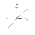
- FIG. 4 is a diagram showing the relationship between the exhaust air-fuel ratio and the output current I when the applied voltage is made constant.
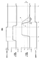
- FIG. 5 is a time chart before and after fuel cut control, such as upstream output current and downstream output current.
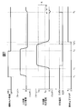
- FIG. 6 is a time chart before and after fuel cut control, such as upstream output current and downstream output current.
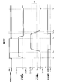
- FIG. 7 is a time chart before and after fuel cut control, such as upstream output current and downstream output current.
- FIG. 8 is a flowchart showing a control routine for controlling applied voltage to the downstream air-fuel ratio sensor.
- FIG. 9 is a time chart before and after fuel cut control, such as upstream output current and downstream output current.
- FIG. 10 is a time chart before and after fuel cut control, such as upstream output current and downstream output current.
- FIG. 11 is a time chart before and after fuel cut control, such as upstream output current and downstream output current.
- FIG. 12 is a flowchart showing a control routine of applied voltage control to the downstream air-fuel ratio sensor and rich control after return.
- FIG. 13 is a diagram schematically showing the structure of a cup-type air-fuel ratio sensor.
- FIG. 1 is a diagram schematically showing an internal combustion engine in which a diagnostic device according to a first embodiment of the present invention is used.
- 1 is an engine body
- 2 is a cylinder block
- 3 is a piston that reciprocates in the cylinder block
- 4 is a cylinder head fixed on the cylinder block
- 5 is a piston 3 and a cylinder head 4.
- a combustion chamber formed therebetween 6 is an intake valve
- 7 is an intake port
- 8 is an exhaust valve
- 9 is an exhaust port.
- the intake valve 6 opens and closes the intake port 7, and the exhaust valve 8 opens and closes the exhaust port 9.
- a spark plug 10 is disposed at the center of the inner wall surface of the cylinder head 4, and a fuel injection valve 11 is disposed around the inner wall surface of the cylinder head 4.
- the spark plug 10 is configured to generate a spark in response to the ignition signal.
- the fuel injection valve 11 injects a predetermined amount of fuel into the combustion chamber 5 according to the injection signal.
- the fuel injection valve 11 may be arranged so as to inject fuel into the intake port 7.
- gasoline having a theoretical air-fuel ratio of 14.6 is used as the fuel.
- other fuels may be used in the internal combustion engine in which the diagnostic device of the present invention is used.
- the intake port 7 of each cylinder is connected to a surge tank 14 via a corresponding intake branch pipe 13, and the surge tank 14 is connected to an air cleaner 16 via an intake pipe 15.
- the intake port 7, the intake branch pipe 13, the surge tank 14, and the intake pipe 15 form an intake passage.
- a throttle valve 18 driven by a throttle valve drive actuator 17 is disposed in the intake pipe 15. The throttle valve 18 is rotated by a throttle valve drive actuator 17 so that the opening area of the intake passage can be changed.
- the exhaust port 9 of each cylinder is connected to an exhaust manifold 19.
- the exhaust manifold 19 has a plurality of branches connected to the exhaust ports 9 and a collective part in which these branches are assembled.
- a collecting portion of the exhaust manifold 19 is connected to an upstream casing 21 containing an upstream exhaust purification catalyst 20.
- the upstream casing 21 is connected to a downstream casing 23 containing a downstream exhaust purification catalyst 24 via an exhaust pipe 22.
- the exhaust port 9, the exhaust manifold 19, the upstream casing 21, the exhaust pipe 22, and the downstream casing 23 form an exhaust passage.
- An electronic control unit (ECU) 31 comprises a digital computer, and is connected to each other via a bidirectional bus 32, a RAM (Random Access Memory) 33, a ROM (Read Only Memory) 34, a CPU (Microprocessor) 35, and an input.
- a port 36 and an output port 37 are provided.
- An air flow meter 39 for detecting the flow rate of air flowing through the intake pipe 15 is disposed in the intake pipe 15, and the output of the air flow meter 39 is input to the input port 36 via the corresponding AD converter 38.
- an upstream air-fuel ratio sensor 40 that detects the air-fuel ratio of the exhaust gas flowing through the exhaust manifold 19 (that is, the exhaust gas flowing into the upstream exhaust purification catalyst 20) is disposed at the collecting portion of the exhaust manifold 19.
- the downstream side that detects the air-fuel ratio of the exhaust gas that flows in the exhaust pipe 22 (that is, the exhaust gas that flows out of the upstream side exhaust purification catalyst 20 and flows into the downstream side exhaust purification catalyst 24).
- An air-fuel ratio sensor 41 is arranged. The outputs of these air-fuel ratio sensors 40 and 41 are also input to the input port 36 via the corresponding AD converter 38. The configuration of these air-fuel ratio sensors 40 and 41 will be described later.
- a load sensor 43 that generates an output voltage proportional to the amount of depression of the accelerator pedal 42 is connected to the accelerator pedal 42, and the output voltage of the load sensor 43 is input to the input port 36 via the corresponding AD converter 38.
- the crank angle sensor 44 generates an output pulse every time the crankshaft rotates 15 degrees, and this output pulse is input to the input port 36.
- the CPU 35 calculates the engine speed from the output pulse of the crank angle sensor 44.
- the output port 37 is connected to the spark plug 10, the fuel injection valve 11, and the throttle valve drive actuator 17 via the corresponding drive circuit 45.
- the upstream side exhaust purification catalyst 20 and the downstream side exhaust purification catalyst 24 are three-way catalysts having oxygen storage capacity.
- the exhaust purification catalysts 20 and 24 support a noble metal having a catalytic action (for example, platinum (Pt)) and a substance having an oxygen storage capacity (for example, ceria (CeO 2 )) on a ceramic support. It has been made.
- a noble metal having a catalytic action for example, platinum (Pt)
- a substance having an oxygen storage capacity for example, ceria (CeO 2 )
- the exhaust purification catalysts 20 and 24 exhibit an oxygen storage capability in addition to the catalytic action of simultaneously purifying unburned gas (HC, CO, etc.) and nitrogen oxides (NOx).
- the exhaust purification catalysts 20, 24 have an air / fuel ratio of exhaust gas flowing into the exhaust purification catalysts 20, 24 leaner than a stoichiometric air / fuel ratio (hereinafter referred to as “lean air / fuel ratio”). Is stored in the exhaust gas.
- the air-fuel ratio of the inflowing exhaust gas is richer than the stoichiometric air-fuel ratio (hereinafter referred to as “rich air-fuel ratio”)
- the exhaust purification catalysts 20, 24 are oxygen stored in the exhaust purification catalysts 20, 24. Release.
- the exhaust gas flowing out from the exhaust purification catalysts 20, 24 is irrespective of the air-fuel ratio of the exhaust gas flowing into the exhaust purification catalysts 20, 24.
- the air-fuel ratio is almost the stoichiometric air-fuel ratio.
- air-fuel ratio of exhaust gas means the ratio of the mass of fuel to the mass of air supplied until the exhaust gas is generated. Normally, combustion is performed when the exhaust gas is generated. It means the ratio of the mass of fuel to the mass of air supplied into the chamber 5.
- the air-fuel ratio of the exhaust gas may be referred to as “exhaust air-fuel ratio”.
- the air-fuel ratio sensors 40 and 41 include a solid electrolyte layer 51, an exhaust-side electrode 52 disposed on one side surface thereof, an atmosphere-side electrode 53 disposed on the other side surface, and diffusion of exhaust gas passing therethrough.
- a diffusion control layer 54 that controls the speed, a protective layer 55 that protects the diffusion control layer 54, and a heater unit 56 that heats the air-fuel ratio sensors 40 and 41 are provided.
- the solid electrolyte layer 51 is an oxygen ion conductive oxide in which ZrO 2 (zirconia), HfO 2 , ThO 2 , Bi 2 O 3, etc. are distributed with CaO, MgO, Y 2 O 3 , Yb 2 O 3 etc. as stabilizers.
- the sintered body is formed.
- the diffusion control layer 54 is formed of a porous sintered body of a heat-resistant inorganic substance such as alumina, magnesia, silica, spinel, mullite or the like.
- the exhaust-side electrode 52 and the atmosphere-side electrode 53 are formed of a noble metal having high catalytic activity such as platinum.
- a sensor applied voltage V is applied between the exhaust side electrode and the atmosphere side electrode by the applied voltage control device 60 mounted on the ECU 31.
- the ECU 31 is provided with a current detection device 61 that detects a current I flowing between the electrodes 52 and 53 via the solid electrolyte layer when a sensor applied voltage is applied.
- the current detected by the current detector 61 is the output current of the air-fuel ratio sensors 40 and 41.
- the thus configured air-fuel ratio sensors 40 and 41 have voltage-current (VI) characteristics as shown in FIG.
- V voltage-current
- the output current I increases as the exhaust air-fuel ratio increases (lean).
- the VI line at each exhaust air-fuel ratio includes a region parallel to the V axis, that is, a region where the output current hardly changes even when the sensor applied voltage changes. This voltage region is referred to as a limiting current region, and the current at this time is referred to as a limiting current.
- the limit current region and limit current when the exhaust air-fuel ratio is 18 are indicated by W 18 and I 18 , respectively.
- the output current changes almost in proportion to the sensor applied voltage.
- a region where the sensor applied voltage is lower than the limit current region.
- the inclination at this time is determined by the DC element resistance of the solid electrolyte layer 51.
- the output current increases as the sensor applied voltage increases. In this region, the output voltage changes according to the change in the sensor applied voltage due to, for example, decomposition of moisture contained in the exhaust gas on the exhaust side electrode 52.
- FIG. 4 is a diagram showing the relationship between the exhaust air-fuel ratio and the output current I when the applied voltage is kept constant at about 0.45V.
- the output current I from the air-fuel ratio sensors 40 and 41 increases as the exhaust air-fuel ratio increases (that is, the leaner the air-fuel ratio).
- the air-fuel ratio sensors 40 and 41 are configured such that the output current I becomes zero when the exhaust air-fuel ratio is the stoichiometric air-fuel ratio. Further, when the exhaust air-fuel ratio becomes larger than a certain value or when it becomes smaller than a certain value, the ratio of the change in the output current to the change in the exhaust air-fuel ratio becomes smaller.
- the limit current type air-fuel ratio sensor having the structure shown in FIG.
- any structure such as a limit current type air-fuel ratio sensor of another structure or an air-fuel ratio sensor not of the limit current type will be used.
- An air-fuel ratio sensor may be used.
- the air-fuel ratio of the exhaust gas flowing into the upstream side exhaust purification catalyst 20 is based on the engine operating state based on the outputs of the upstream side air-fuel ratio sensor 40 and the downstream side air-fuel ratio sensor 41.
- the fuel injection amount from the fuel injection valve 11 is set so as to achieve an optimal air-fuel ratio.
- control is performed so that the air-fuel ratio of the exhaust gas flowing into the upstream side exhaust purification catalyst 20 becomes the target air-fuel ratio based on the output of the upstream side air-fuel ratio sensor 40, and the downstream side. Examples include a method of correcting the output of the upstream air-fuel ratio sensor 40 based on the output of the side air-fuel ratio sensor 41 or changing the target air-fuel ratio.
- Fuel cut control is performed to stop or significantly reduce the fuel supply to the inside.
- Such fuel cut control is performed by, for example, a predetermined rotational speed in which the depression amount of the accelerator pedal 42 is zero or almost zero (that is, the engine load is zero or almost zero) and the engine speed is higher than the idling speed.
- the air-fuel ratio sensors 40 and 41 have extremely high air-fuel ratios (that is, You will be exposed to gas with a very high degree of lean.
- FIG. 5 is a time chart of the output current of the upstream side air-fuel ratio sensor 40, the oxygen storage amount of the upstream side exhaust purification catalyst 20, and the output current of the downstream side air-fuel ratio sensor 41 when the fuel cut control is performed. is there.
- the output current of the air-fuel ratio sensors 40 and 41 becomes zero when the exhaust air-fuel ratio is the stoichiometric air-fuel ratio, and increases as the exhaust air-fuel ratio becomes leaner.
- fuel cut control is started at time t 1 and fuel cut control is ended at time t 3 .
- the lean air-fuel ratio exhaust gas is discharged from the engine body 1, and accordingly, the output current of the upstream air-fuel ratio sensor 40 increases.
- oxygen in the exhaust gas flowing into the upstream side exhaust purification catalyst 20 is stored in the upstream side exhaust purification catalyst 20, so that the oxygen storage amount of the upstream side exhaust purification catalyst 20 increases, while the downstream side air-fuel ratio.
- the output current of the sensor 41 remains zero (corresponding to the theoretical air / fuel ratio).
- the upstream side exhaust purification catalyst 20 can no longer store oxygen. For this reason, after time t 2 , the output current of the downstream air-fuel ratio sensor 41 becomes larger than zero.
- the rich control after the return is performed in order to release the oxygen stored in the upstream side exhaust purification catalyst 20 during the fuel cut control.
- the exhaust gas having an air-fuel ratio richer than the stoichiometric air-fuel ratio is discharged from the engine body 1.
- the output current of the upstream side air-fuel ratio sensor 40 becomes smaller than 0, and the oxygen storage amount of the upstream side exhaust purification catalyst 20 gradually decreases.
- the air-fuel ratio of the exhaust gas discharged from the side exhaust purification catalyst 20 is substantially the stoichiometric air-fuel ratio. For this reason, the output air-fuel ratio of the downstream air-fuel ratio sensor 41 is substantially zero.
- the oxygen storage amount continues to decrease, the oxygen storage amount eventually becomes almost zero, and unburned gas flows out from the upstream side exhaust purification catalyst 20.
- the exhaust air-fuel ratio detected by the downstream air-fuel ratio sensor 41 decreases to an end determination air-fuel ratio that is richer than the stoichiometric air-fuel ratio.
- the output current of the downstream air-fuel ratio sensor 41 reaches the end determination current slightly smaller than zero (corresponding to the end determination air-fuel ratio) for the first time after the start of the rich control after the return, the rich control after the return is performed. It will be terminated. Thereafter, normal air-fuel ratio control is started, and in the illustrated example, control is performed so that the air-fuel ratio of the exhaust gas discharged from the engine body becomes the stoichiometric air-fuel ratio.
- condition for ending the rich control after return does not necessarily have to be when the rich air-fuel ratio is detected by the downstream air-fuel ratio sensor 41.
- the condition for ending the rich control after return does not necessarily have to be when the rich air-fuel ratio is detected by the downstream air-fuel ratio sensor 41.
- abnormality diagnosis control examples include control performed based on the outputs of the air-fuel ratio sensors 40 and 41 immediately after the end of the fuel cut control.
- responsiveness deterioration of the downstream air-fuel ratio sensor 41 that is, deterioration in which the output of the air-fuel ratio sensor is delayed with respect to changes in the air-fuel ratio around the air-fuel ratio sensor
- FIG. 6 is a time chart of the upstream air-fuel ratio sensor output current (upstream output current), downstream air-fuel ratio sensor output current (downstream output current), and diagnosis completion flag before and after execution of fuel cut control.
- fuel cut control is started at time t 1 and fuel cut control is ended at time t 3 .
- the rich air-fuel ratio exhaust gas is caused to flow into the upstream side exhaust purification catalyst 20 by the rich control after the return.
- the air-fuel ratio of the exhaust gas discharged from the upstream side exhaust purification catalyst 20 is the stoichiometric air-fuel ratio.
- the output current of the downstream air-fuel ratio sensor 41 changes as indicated by the solid line A in FIG. That is, since there is a distance from the engine body 1 to the downstream air-fuel ratio sensor 41 after the fuel cut control is finished, the output current of the downstream air-fuel ratio sensor 41 starts to decrease after a certain delay from the end of the fuel cut control. . At this time, since the air-fuel ratio of the exhaust gas flowing out from the upstream side exhaust purification catalyst 20 is substantially the stoichiometric air-fuel ratio, the output current of the downstream side air-fuel ratio sensor 41 converges to zero.
- the output current of the downstream air-fuel ratio sensor 41 changes as indicated by a broken line B in FIG. That is, the rate of decrease in the output current is slower than when the downstream air-fuel ratio sensor 41 has not deteriorated in responsiveness (solid line A).
- the rate of decrease in the output current of the downstream air-fuel ratio sensor 41 changes depending on whether or not the response deterioration of the downstream air-fuel ratio sensor 41 has occurred. Therefore, by calculating this rate of decrease, it is possible to diagnose whether or not the downstream air-fuel ratio sensor 41 has deteriorated responsiveness.
- the output current of the downstream air-fuel ratio sensor 41 is approximately equal to the air-fuel ratio of 18 (I 18 ) and the air-fuel ratio of about 16 during the execution of the rich control after the fuel cut control is completed.
- the change rate of the output current (hereinafter referred to as “determination current change rate”) when passing through a predetermined current region X (hereinafter referred to as “determination current region”) between the value corresponding to (I 16 ) ) Is calculated.
- the time ⁇ T during which the output current changes from the upper limit value (ie, I 18 ) to the lower limit value (ie, I 16 ) of the determination current region is used as a parameter representing the determination current change rate.
- the determination current change time ⁇ T becomes longer as the determination current change time ⁇ T becomes longer.
- the determination current change times ⁇ T 1 and ⁇ T 2 in FIG. 1 are parameters representing the determination air-fuel ratio change rates for the solid line A and the broken line B, respectively.
- the abnormality diagnosis of the downstream air-fuel ratio sensor 41 is performed based on the determination current change time ⁇ T calculated in this way. Specifically, when the determination current change time ⁇ T is longer than the abnormal reference change time (for example, ⁇ T 2 ), that is, when the determination current change speed is slower than the abnormal reference change speed, the downstream air-fuel ratio. It is determined that an abnormality of responsiveness deterioration has occurred in the sensor 41. Conversely, when the determination current change time ⁇ T is shorter than the abnormal reference change time (for example, ⁇ T 1 ), that is, when the determination current change speed is faster than the abnormal reference change speed, the downstream air-fuel ratio sensor 41. It is determined that there is no abnormality in response deterioration.
- the abnormality reference change time may be a predetermined value, or may be a value that changes in accordance with operating parameters such as engine speed and engine load during rich control after return.
- the diagnosis of the abnormality of the downstream side air-fuel ratio sensor 41 is completed.
- the completion flag is changed to 1.
- the diagnosis completion flag is reset to 0 when the ignition key is turned off and the system of the vehicle equipped with the internal combustion engine is turned off, and is set to 1 when the abnormality diagnosis is completed after the internal combustion engine is started. Flag.
- the state where the fuel cut control is performed that is, the state where the air-fuel ratio of the exhaust gas passing around the downstream air-fuel ratio sensor 41 is extremely high (the degree of leanness is extremely high)
- An abnormality diagnosis is performed when the air-fuel ratio of the exhaust gas passing around the fuel ratio sensor 41 changes to the stoichiometric air-fuel ratio.
- a warning lamp is lit in a vehicle equipped with an internal combustion engine.
- the abnormality diagnosis control is not necessarily performed after the end of each fuel cut control, but is performed when a certain execution condition is satisfied. As such execution conditions, the downstream air-fuel ratio sensor 41 has been heated to the activation temperature or higher, and the abnormality diagnosis control has not been executed a predetermined number of times since the start of the vehicle system equipped with the internal combustion engine. And so on.
- abnormality diagnosis control for diagnosing abnormality of responsiveness deterioration of the downstream air-fuel ratio sensor 41 is performed after completion of the fuel cut control.
- any abnormality diagnosis control may be performed as long as the abnormality diagnosis is performed based on the outputs of the air-fuel ratio sensors 40 and 41 after the end of the fuel cut control.
- the applied voltage at the downstream air-fuel ratio sensor 41 is set to about 0.45V.
- the exhaust air-fuel ratio can be appropriately detected in the vicinity of the theoretical air-fuel ratio.
- FIG. 7 shows the output current of the upstream air-fuel ratio sensor (upstream output current), the output current of the downstream air-fuel ratio sensor (downstream output current), and the downstream air-fuel ratio sensor 41 before and after execution of the fuel cut control. It is a time chart of an applied voltage and a diagnosis completion flag.
- the voltage applied to the downstream air-fuel ratio sensor 41 is reduced to 0.2 V during the fuel cut control.
- the applied voltage to the downstream air-fuel ratio sensor 41 is reduced from 0.45 V to 0.2 V. .
- the maximum value that the output current can take increases as the applied voltage increases. Therefore, if the applied voltage to the downstream air-fuel ratio sensor 41 is 0.2 V, even when the same gas as the atmospheric gas (the atmospheric gas in FIG. 3) is circulating around the downstream air-fuel ratio sensor 41.
- the downstream air-fuel ratio sensor 41 does not generate an output current exceeding I 0.2 AIR (a value lower than I 0.45 AIR ). As a result, generation of an excessive output current from the downstream air-fuel ratio sensor 41 can be suppressed.
- the output current of the downstream air-fuel ratio sensor 41 decreases to I 18 as indicated by the broken line in FIG.
- the applied voltage is raised from 0.2V to 0.45V.
- both the rich air-fuel ratio and the lean air-fuel ratio are within a certain range centering on the theoretical air-fuel ratio.
- the air-fuel ratio can be detected.
- the applied voltage of the downstream air-fuel ratio sensor 41 is 0.2 V
- the air-fuel ratio can be detected over a certain range for the rich air-fuel ratio, but the lean air-fuel ratio is about 18 or more. It is impossible to detect the air-fuel ratio. That is, when the applied voltage of the downstream air-fuel ratio sensor 41 is lowered to 0.2 V, the range in which the air-fuel ratio can be detected becomes inappropriate.
- the air-fuel ratio can be detected over a certain range around the theoretical air-fuel ratio during normal operation. Become. As a result, after the fuel cut control is completed, it becomes possible to detect an air-fuel ratio in a range necessary for normal operation.
- the applied voltage is increased after the output current of the downstream air-fuel ratio sensor 41 has decreased to I 18 .
- the applied voltage is increased before the output current of the downstream air-fuel ratio sensor 41 decreases to I 18 , the output current of the downstream air-fuel ratio sensor 41 exceeds I 0.2 AIR as the applied voltage increases. It will rise.
- an excessive output current is input to the electric circuit connected to the downstream air-fuel ratio sensor 41, and if an electric circuit with a small capacity is used, the electric circuit is damaged.
- the applied voltage is increased after the output current of the downstream air-fuel ratio sensor 41 has decreased to I 18, an excessive output current is generated from the downstream air-fuel ratio sensor 41. Is suppressed.
- the applied voltage of the downstream air-fuel ratio sensor 41 is switched stepwise, noise is temporarily generated in the output current of the downstream air-fuel ratio sensor 41. For this reason, the air-fuel ratio of the exhaust gas flowing around the downstream air-fuel ratio sensor 41 cannot be accurately detected immediately after changing the applied voltage.
- the applied voltage is switched when the output current of the downstream air-fuel ratio sensor 41 drops to I 18, and the applied voltage is quickly switched while suppressing the generation of an excessive output current. . For this reason, in some cases, noise that occurs due to switching of the applied voltage can be terminated before the output current of the downstream air-fuel ratio sensor 41 reaches zero corresponding to the theoretical air-fuel ratio.
- the normal voltage that is the applied voltage during normal operation is 0.45 V
- the fuel cut voltage that is the applied voltage during fuel cut control is 0.2 V.
- the normal voltage and the fuel cut voltage do not necessarily have this value.
- the fuel cut voltage is required to be lower than the normal operation voltage.
- the fuel cut voltage is a voltage at which the output current of the downstream air-fuel ratio sensor 41 becomes equal to or less than the maximum allowable current of the electric circuit even if a gas similar to the atmospheric gas flows around the downstream air-fuel ratio sensor 41. It is said.
- the fuel cut voltage is higher than the lower limit voltage (V low in FIG. 3) in the limit current region when the downstream air-fuel ratio sensor 41 is exposed to the exhaust gas having the stoichiometric air-fuel ratio.
- the fuel cut voltage is higher than the lower limit voltage in the limit current region of the air-fuel ratio sensor when the downstream air-fuel ratio sensor 41 is exposed to a gas having a predetermined lean air-fuel ratio (for example, air-fuel ratio 18).
- the voltage In this case, the voltage applied to the downstream air-fuel ratio sensor 41 is less than or equal to a value (for example, I 18 ) corresponding to the predetermined lean air-fuel ratio (for example, air-fuel ratio 18). When this happens, the fuel cut voltage is raised to the normal voltage.
- the timing at which the fuel cut control is finished and the applied voltage to the downstream air-fuel ratio sensor 41 is increased is not necessarily the value I 18 or less corresponding to the air-fuel ratio at which the output current of the downstream air-fuel ratio sensor 41 is about 18. It does not have to be when it drops. Therefore, it may be when the output current of the downstream air-fuel ratio sensor 41 becomes equal to or less than a predetermined value (a value greater than zero) other than I 18 . However, it is preferable that the output current when increasing the voltage applied to the downstream air-fuel ratio sensor 41 is a limit current.
- the rich control after return is ended. That is, in the present embodiment, when the oxygen storage amount of the upstream side exhaust purification catalyst 20 becomes substantially zero and the unburned gas begins to flow out of the upstream side exhaust purification catalyst 20, the rich control after returning is terminated. However, if noise occurs in the output current of the downstream side air-fuel ratio sensor 41 when the unburned gas starts to flow out of the upstream side exhaust purification catalyst 20, the outflow of unburned gas can be accurately detected. It will disappear.
- the applied voltage of the downstream air-fuel ratio sensor 41 is raised from 0.2V to 0.45V at time t 4.
- the abnormality diagnosis control is completed before the output current of the downstream air-fuel ratio sensor 41 reaches the end determination current.
- the abnormality diagnosis control is completed after the output current of the downstream air-fuel ratio sensor 41 reaches the end determination current. In such a case, the voltage applied to the downstream air-fuel ratio sensor 41 is increased after the abnormality diagnosis control is completed.
- the applied voltage is increased after the later of the abnormality diagnosis control and the end of the rich control after return, whichever is later.
- the increase in the applied voltage occurs after the return rich control is finished and after the output current of the downstream air-fuel ratio sensor 41 once converges to zero and before it becomes lower than zero again (that is, the upstream side exhaust purification catalyst). It is preferably performed before the exhaust gas having a rich air-fuel ratio flows from 20 or before becoming higher than zero (that is, before the exhaust gas having a lean air-fuel ratio flows from the upstream side exhaust purification catalyst 20).
- the increase in the applied voltage occurs after the rich control is completed after the return and before the output current of the downstream air-fuel ratio sensor 41 converges from the end determination current or less to zero (corresponding to the theoretical air-fuel ratio) (M in FIG. 7). During the indicated period).
- the increase in applied voltage is after the output current of the downstream air-fuel ratio sensor 41 has converged from below the end determination current to zero (corresponding to the theoretical air-fuel ratio) after completion of rich control after return, and then near zero. It may be performed before the change. As a result, the applied voltage is increased when there is almost no fluctuation in the output of the downstream side air-fuel ratio sensor 41.
- FIG. 8 is a flowchart showing a control routine for controlling applied voltage to the downstream air-fuel ratio sensor 41.
- the illustrated control routine is performed by interruption at regular time intervals.
- step S11 it is determined whether or not the voltage drop flag Fv is 1.
- the voltage drop flag Fv is a flag that is set to 1 when the applied voltage of the downstream side air-fuel ratio sensor 41 is decreased, and is set to 0 in other cases. If it is determined in step S11 that the voltage drop flag is 0, the process proceeds to step S12. In step S12, it is determined whether fuel cut control is started. When it is determined that the fuel cut control has not been started, the control routine is terminated. On the other hand, if it is determined in step S12 that the fuel cut control has been started, the process proceeds to step S13. In step S13, the voltage applied to the downstream air-fuel ratio sensor 41 is reduced to 0.2V. Next, at step S14, the voltage drop flag Fv is set to 1, and the control routine is ended.
- step S11 it is determined in step S11 that the voltage drop flag Fv is 1, and the process proceeds to step S15.
- step S15 it is determined whether or not the fuel cut control is finished. If it is determined that the fuel cut control has not ended, the control routine is ended. As a result, the voltage applied to the downstream air-fuel ratio sensor 41 is maintained at 0.2V.
- step S16 it is determined whether or not the abnormality diagnosis control is completed. If it is determined that the abnormality diagnosis control has not been completed, the control routine is terminated. As a result, the voltage applied to the downstream air-fuel ratio sensor 41 is maintained at 0.2V.
- step S17 it is determined whether or not the output current of the downstream air-fuel ratio sensor 41 is equal to or less than the end determination current Iref.
- the control routine is ended. Also in this case, the voltage applied to the downstream air-fuel ratio sensor 41 is maintained at 0.2V.
- step S18 the voltage applied to the downstream air-fuel ratio sensor 41 is increased to 0.45V.
- step S19 the voltage drop flag Fv is reset to 0, and the control routine is ended.
- the voltage applied to the downstream air-fuel ratio sensor 41 has been described.
- the voltage applied to the upstream air-fuel ratio sensor 40 can be similarly controlled.
- the upstream air-fuel ratio sensor 40 is not used to detect the unburned gas flowing out of the upstream side exhaust purification catalyst 20 in order to end the rich control after the return. Accordingly, the voltage applied to the upstream air-fuel ratio sensor 40 is raised when the abnormality diagnosis control is completed when the abnormality diagnosis control is executed.
- the voltage applied to the upstream air-fuel ratio sensor 40 decreases the output current of the upstream air-fuel ratio sensor 40 to I 18 as in the case of the downstream air-fuel ratio sensor 41. Sometimes raised.
- the configuration of the control device for the internal combustion engine is basically the same as the configuration of the control device of the first embodiment.
- the downstream air-fuel ratio sensor is terminated. Regardless of the output current 41, the rich control is terminated after the return.
- the post-recovery rich control ends based on the integrated flow rate of exhaust gas flowing into the upstream side exhaust purification catalyst 20. I'm damned.
- the integrated flow rate of the exhaust gas flowing into the upstream side exhaust purification catalyst 20 is estimated based on the output of the air flow meter 39, for example.
- FIG. 9 is a time chart similar to FIG. 7 showing the upstream output current and the like before and after execution of the fuel cut control.
- integration of the exhaust gas flowing into the upstream side exhaust purification catalyst 20 is started from the end of the fuel cut control, that is, from the start of the rich control after return (time t 3 ).
- the integrated flow rate of the exhaust gas flowing into the upstream side exhaust purification catalyst 20 reaches a predetermined value ⁇ Vref at time t 7 , the rich control after returning is terminated.
- the output current of the upstream air-fuel ratio sensor 40 is raised to zero (corresponding to the theoretical air-fuel ratio).
- the output current of the downstream air-fuel ratio sensor 41 is not used to determine the end timing of the post-return rich control. For this reason, it is not necessary to accurately detect the timing at which the output current becomes the end determination current by the downstream air-fuel ratio sensor 41 after the start of the rich control after the return. Therefore, in this embodiment, when the abnormality diagnosis control after the fuel cut control ends, when the abnormality diagnosis control at time t 4 is completed, the applied voltage of the downstream air-fuel ratio sensor 41 from 0.2V 0.45 V It is raised to. Thus, after the fuel cut control is completed, the range of the air-fuel ratio that can be detected by the downstream air-fuel ratio sensor 41 can be quickly switched to an appropriate range.
- the timing for increasing the voltage applied to the downstream air-fuel ratio sensor 41 is not necessarily the same as the end of the abnormality diagnosis control as long as it is after the end of the abnormality diagnosis control.
- the increase in the applied voltage is delayed, the period in which the range in which the air-fuel ratio can be detected is inappropriate is increased accordingly. Therefore, it is preferable to raise the applied voltage after the return and before the end of the rich control.
- the end of the rich control after the return is determined based on the integrated flow rate of the exhaust gas flowing into the upstream side exhaust purification catalyst 20.
- the end of the return rich control may be determined based on other parameters as long as it is a parameter other than the output current of the downstream air-fuel ratio sensor 41.
- Such parameters include, for example, the time from the start of rich control after return, the integrated fuel injection amount from the start of rich control after return, and the like.
- the configuration of the control device for the internal combustion engine is basically the same as the configuration of the control device of the first and second embodiments.
- the end timing of the return rich control is the same regardless of whether or not the abnormality diagnosis control is executed.
- the end timing of the rich control after return is changed according to whether or not the abnormality diagnosis control is executed.
- the output current of the downstream air-fuel ratio sensor 41 has decreased to the end determination current.
- the rich control is ended after returning. Therefore, the rich air-fuel ratio exhaust gas flows into the upstream side exhaust purification catalyst 20 until time t 4, and as a result, the output current of the upstream side air-fuel ratio sensor 40 converges to zero after time t 4 .
- the voltage applied to the downstream air-fuel ratio sensor 41 is 0.2 V to 0.45 V at time t 6 (when the output current of the downstream air-fuel ratio sensor 41 drops to I 18 ). It is raised to.
- the return rich control end timing is based on the integrated flow rate of the exhaust gas flowing into the upstream side exhaust purification catalyst 20. To be determined. Therefore, when the integrated flow rate reaches a predetermined value ⁇ Vref (time t 7 ), the rich control after return is terminated.
- the voltage applied to the downstream-side air-fuel ratio sensor 41 0. Increased from 2V to 0.45V.
- the rich control when the abnormality diagnosis control is not performed, the rich control is terminated after the return after the output current of the downstream side air-fuel ratio sensor 41 has decreased to the termination determination current. Therefore, the rich control can be performed after returning until all the oxygen stored in the upstream side exhaust purification catalyst 20 is released, and thereby the oxygen storage capacity of the upstream side exhaust purification catalyst 20 can be increased.
- the abnormality diagnosis control when the abnormality diagnosis control is performed, the post-return rich control is terminated regardless of the output current of the downstream air-fuel ratio sensor 41. For this reason, in determining the end time of the abnormality diagnosis control, it is possible to avoid the influence of noise accompanying switching of the applied voltage to the downstream air-fuel ratio sensor 41.
- FIG. 12 is a flowchart showing a control routine of applied voltage control to the downstream air-fuel ratio sensor 41 and rich control after return.
- the illustrated control routine is performed by interruption at regular time intervals. Steps S21 to S25 are the same as steps S11 to S15 in FIG.
- step S25 When it is determined in step S25 that the fuel cut control has been completed, the process proceeds to step S26.
- step S26 it is determined whether or not the post-return rich flag Fr is 1.
- the post-return rich flag Fr is a flag that is set to 1 when the post-return rich control is being executed, and is set to 0 otherwise. If rich control after return has not yet been started, it is determined in step S25 that the rich flag Fr after return is not 1, and the process proceeds to step S27.
- step S27 after-return rich control is started, and then in step S28, the after-return rich flag Fr is set to 1, and the control routine is ended.
- step S26 it is determined in step S26 that the rich flag Fr after return is set to 1, and the process proceeds to step S29.
- step S29 it is determined whether or not abnormality diagnosis control has been executed after the end of fuel cut control. If it is determined that the abnormality diagnosis control has been executed, the process proceeds to step S30.
- step S30 it is determined whether or not the abnormality diagnosis control is completed. When it is determined that the abnormality diagnosis control is not completed, the control routine is ended. As a result, the voltage applied to the downstream air-fuel ratio sensor 41 is maintained at 0.2 V, and the rich control is continued after the return.
- step S30 the process proceeds from step S30 to step S31, and the applied voltage to the downstream side air-fuel ratio sensor 41 is increased to 0.45V.
- step S32 the rich control after return is terminated, in step S33, the voltage drop flag Fv is reset to 0, and in step S34, the rich flag Fr after return is reset to 0, and the control routine ends. I'm damned.
- step S35 it is determined whether or not the output current I of the downstream air-fuel ratio sensor 41 has become equal to or less than I 18 (a value corresponding to the air-fuel ratio 18). If it is determined that the output current I of the downstream air-fuel ratio sensor 41 is higher than I 18 , the control routine is ended. As a result, the voltage applied to the downstream air-fuel ratio sensor 41 is maintained at 0.2 V, and the rich control is continued after the return. Thereafter, when the output current I of the downstream side air-fuel ratio sensor 41 decreases to I 18 or less, in the next control routine, the process proceeds from step S35 to step S31, steps S31 to S34 are executed, and the control routine is ended.
- the upstream side air-fuel ratio sensor 40 and the downstream side air-fuel ratio sensor 41 are stacked limit current type air-fuel ratio sensors as shown in FIG.
- these air-fuel ratio sensors may be cup-type limit current air-fuel ratio sensors.
- FIG. 13 is a diagram schematically showing the structure of the cup-type air-fuel ratio sensors 40 ′ and 41 ′.
- the cup-type air-fuel ratio sensors 40 ′ and 41 ′ include a solid electrolyte layer 51 ′ configured in a cup shape (cylindrical shape), and an exhaust-side electrode 52 ′ disposed on the outer surface thereof. And an atmosphere-side electrode 53 ′ disposed on the inner surface thereof, a diffusion-controlling layer 54 ′ for controlling the diffusion of exhaust gas passing therethrough, and a heater unit 56 ′ for heating the air-fuel ratio sensors 40 ′ and 41 ′. It has. As can be seen from FIG.
- the diffusion-controlling layer 54 ′ is configured in a cup shape (cylindrical shape) so as to cover the outer surface of the solid electrolyte layer 51 ′, and the heater portion 56 ′ is formed of the solid electrolyte layer 51 ′. Arranged inside.
- the entire outer peripheral surface of the diffusion rate controlling layer 54 ′ is exposed to the exhaust gas.
- the flow rate of the exhaust gas reaching the exhaust side electrode 52 'increases, and the current generated between the electrodes increases.
- the output current becomes larger than in the stacked-type air-fuel ratio sensor, and the load on the electric circuit increases.
- the load on the electric circuit can be more effectively reduced by performing the control of the above embodiment.
- the types of the upstream air-fuel ratio sensor and the downstream air-fuel ratio sensor are not necessarily unified.
- the upstream air-fuel ratio sensor is a stacked air-fuel ratio sensor
- the downstream air-fuel ratio sensor is a cup-type air-fuel ratio sensor.
- An air-fuel ratio sensor may be used.
Landscapes
- Engineering & Computer Science (AREA)
- Chemical & Material Sciences (AREA)
- Combustion & Propulsion (AREA)
- Mechanical Engineering (AREA)
- General Engineering & Computer Science (AREA)
- Health & Medical Sciences (AREA)
- Life Sciences & Earth Sciences (AREA)
- Physics & Mathematics (AREA)
- Chemical Kinetics & Catalysis (AREA)
- Electrochemistry (AREA)
- Molecular Biology (AREA)
- Analytical Chemistry (AREA)
- Biochemistry (AREA)
- General Health & Medical Sciences (AREA)
- General Physics & Mathematics (AREA)
- Immunology (AREA)
- Pathology (AREA)
- Combined Controls Of Internal Combustion Engines (AREA)
- Electrical Control Of Air Or Fuel Supplied To Internal-Combustion Engine (AREA)
- Exhaust Gas After Treatment (AREA)
Abstract
Description
図1を参照すると1は機関本体、2はシリンダブロック、3はシリンダブロック2内で往復動するピストン、4はシリンダブロック2上に固定されたシリンダヘッド、5はピストン3とシリンダヘッド4との間に形成された燃焼室、6は吸気弁、7は吸気ポート、8は排気弁、9は排気ポートをそれぞれ示す。吸気弁6は吸気ポート7を開閉し、排気弁8は排気ポート9を開閉する。
本実施形態では、空燃比センサ40、41としては、積層型の限界電流式の空燃比センサが用いられる。図2を用いて、空燃比センサ40、41の構造について簡単に説明する。空燃比センサ40、41は、固体電解質層51と、その一方の側面上に配置された排気側電極52と、その他方の側面上に配置された大気側電極53と、通過する排気ガスの拡散律速を行う拡散律速層54と、拡散律速層54を保護する保護層55と、空燃比センサ40、41の加熱を行うヒータ部56とを具備する。
このように構成された内燃機関では、上流側空燃比センサ40及び下流側空燃比センサ41の出力に基づいて、上流側排気浄化触媒20に流入する排気ガスの空燃比が機関運転状態に基づいた最適な空燃比となるように、燃料噴射弁11からの燃料噴射量が設定される。このような燃料噴射量の設定方法としては、上流側空燃比センサ40の出力に基づいて上流側排気浄化触媒20に流入する排気ガスの空燃比が目標空燃比となるように制御すると共に、下流側空燃比センサ41の出力に基づいて上流側空燃比センサ40の出力を補正したり、目標空燃比を変更したりする方法が挙げられる。
上述したように、空燃比センサ40、41に基づいて燃料噴射量を設定する場合には、空燃比センサ40、41に異常が生じて、空燃比センサ40、41の出力の精度が悪化してしまうと、燃料噴射量を最適に設定することができなくなる。その結果、排気エミッションの悪化や燃費の悪化を招いてしまう。このため、多くの内燃機関では、空燃比センサ40、41の異常を自己診断する異常診断制御が行われる。
ところで、本実施形態では、通常運転時(燃料カット制御を実行していない時)においては、下流側空燃比センサ41における印加電圧は0.45V程度とされる。これにより、図3からわかるように、理論空燃比近傍において排気空燃比を適切に検出することができる。
ところで、上述したように、下流側空燃比センサ41への印加電圧をステップ的に切り替えると、下流側空燃比センサ41の出力電流に一時的にノイズが発生する。このため、上述したように燃料カット制御の終了直後に異常診断制御を行った場合、異常診断制御の実行中に下流側空燃比センサ41の出力電流にノイズが発生することになる。このように異常診断制御の実行中に下流側空燃比センサ41の出力電流にノイズが発生すると、下流側空燃比センサ41の異常を正確に検出することができない。
図8は、下流側空燃比センサ41への印加電圧制御の制御ルーチンを示すフローチャートである。図示した制御ルーチンは一定時間間隔の割り込みによって行われる。
次に、図9を参照して本発明の第二実施形態について説明する。内燃機関の制御装置の構成等は基本的に第一実施形態の制御装置の構成等と同様である。しかしながら、第一実施形態では、下流側空燃比センサ41の出力電流が終了判定電流に達した時に復帰後リッチ制御を終了させているのに対して、第二実施形態では、下流側空燃比センサ41の出力電流とは無関係に復帰後リッチ制御を終了されている。
次に、図10を参照して、本発明の第三実施形態について説明する。内燃機関の制御装置の構成等は基本的に第一実施形態及び第二実施形態の制御装置の構成等と同様である。しかしながら、上記実施形態では、異常診断制御の実行の有無にかかわらず、復帰後リッチ制御の終了タイミングは同一である。これに対して、本実施形態では、異常診断制御の実行の有無に応じて、復帰後リッチ制御の終了タイミングを変更することとしている。
図12は、下流側空燃比センサ41への印加電圧制御及び復帰後リッチ制御の制御ルーチンを示すフローチャートである。図示した制御ルーチンは一定時間間隔の割り込みによって行われる。なお、ステップS21~S25はそれぞれ図8のステップS11~S15と同様であるため説明を省略する。
なお、上記実施形態では、上流側空燃比センサ40及び下流側空燃比センサ41は図2に示したような積層型の限界電流式空燃比センサとされている。しかしながら、これら空燃比センサは、コップ型の限界電流式空燃比センサとしてもよい。
5 燃焼室
7 吸気ポート
9 排気ポート
19 排気マニホルド
20 上流側排気浄化触媒
24 下流側排気浄化触媒
31 ECU
40 上流側空燃比センサ
41 下流側空燃比センサ
Claims (13)
- 内燃機関の排気通路に設けられた空燃比センサと、該空燃比センサへの印加電圧を制御する印加電圧制御装置とを具備し、内燃機関の作動中に燃焼室への燃料供給を停止又は減量する燃料カット制御と、燃料カット制御の終了後に前記空燃比センサの電流出力に基づいて空燃比センサの異常診断を行う異常診断制御とを実行する内燃機関の制御装置において、
前記空燃比センサは、検出対象である排気ガスの空燃比が高くなるほど出力電流が大きくなると共に、当該空燃比センサへの印加電圧が高くなるほど出力電流の最大値が大きくなるように構成されており、
前記印加電圧制御装置は、前記燃料カット制御の実行中及び該燃料カット制御が終了してから前記異常診断制御が完了するまでは、前記空燃比センサへの印加電圧を、前記燃料カット制御を実行していないときに加える通常電圧とは異なる燃料カット電圧にすると共に、前記異常診断制御が完了した時以降に前記空燃比センサへの印加電圧を前記燃料カット電圧から前記通常電圧に変更する、内燃機関の制御装置。 - 前記内燃機関は機関排気通路に設けられた排気浄化触媒を具備し、前記空燃比センサは前記排気浄化触媒の排気流れ方向下流側に設けられ、当該内燃機関の制御装置は、前記燃料カット制御の終了後に前記排気浄化触媒に流入する排気ガスの空燃比を理論空燃比よりもリッチなリッチ空燃比に制御する復帰後リッチ制御を実行する、請求項1に記載の内燃機関の制御装置。
- 前記印加電圧制御装置は、前記異常診断制御が完了した時及び前記復帰後リッチ制御が終了した時のうちいずれか遅い時以降に前記空燃比センサへの印加電圧を前記燃料カット電圧から前記通常電圧に変更する、請求項2に記載の内燃機関の制御装置。
- 前記印加電圧制御装置は、復帰後リッチ制御の終了後に再度前記空燃比センサの出力電流が理論空燃比に相当する値よりも低くになる前に、前記空燃比センサへの印加電圧を前記燃料カット電圧から前記通常電圧に変更する、請求項3に記載の内燃機関の制御装置。
- 前記復帰後リッチ制御は、前記空燃比センサの出力電流が理論空燃比よりもリッチな終了判定空燃比に相当する終了判定電流以下になったときに終了せしめられる、請求項3又は4に記載の内燃機関の制御装置。
- 前記印加電圧制御装置は、復帰後リッチ制御の終了後であって前記空燃比センサの出力電流が前記終了判定電流以下から理論空燃比に相当する電流に変化する前に、前記空燃比センサへの印加電圧を前記燃料カット電圧から前記通常電圧に変更する、請求項5に記載の内燃機関の制御装置。
- 前記復帰後リッチ制御は、前記空燃比センサの出力電流によらずに他のパラメータに基づいて終了せしめられ、
前記印加電圧制御装置は、前記異常診断制御が完了した後であって前記復帰後リッチ制御の終了前に前記空燃比センサへの印加電圧を前記燃料カット電圧から前記通常電圧に変更する、請求項2に記載の内燃機関の制御装置。 - 前記燃料カット制御の終了時に前記異常診断制御の実行条件が成立していないときには、前記燃料カット制御の終了後であっても前記異常診断制御は実行されず、
前記燃料カット制御の終了後に前記異常診断制御が実行されないときには、前記復帰後リッチ制御は、復帰後リッチ制御を開始してから初めて前記空燃比センサの出力電流が予め定められた終了判定空燃比に相当する値となった時以降に終了せしめられ、
前記燃料カット制御の終了後に前記異常診断制御が実行されるときには、前記復帰後リッチ制御は、前記空燃比センサの出力電流によらずに他のパラメータに基づいて終了せしめられる、請求項7に記載の内燃機関の制御装置。 - 前記燃料カット制御の終了時に前記異常診断制御の実行条件が成立していないときには、前記燃料カット制御の終了後であっても前記異常診断制御は実行されず、
前記印加電圧制御装置は、前記燃料カット制御の終了後に前記異常診断制御が実行されないときには、前記燃料カット制御の終了後、前記空燃比センサの出力電流が予め定められた値以下になったときに、前記空燃比センサへの印加電圧を前記燃料カット電圧から前記通常電圧に変更する、請求項1~8のいずれか1項に記載の内燃機関の制御装置。 - 前記燃料カット電圧は前記通常電圧よりも低い、請求項1~9のいずれか1項に記載の内燃機関の制御装置。
- 前記燃料カット電圧は、前記空燃比センサが理論空燃比のガスに曝されているときにおける空燃比センサの限界電流領域の下限電圧よりも高い、請求項10に記載の内燃機関の制御装置。
- 前記燃料カット制御の終了時に前記異常診断制御の実行条件が成立していないときには、前記燃料カット制御の終了後であっても前記異常診断制御は実行されず、
前記燃料カット電圧は、前記空燃比センサが所定のリーン空燃比のガスに曝されているときにおける空燃比センサの限界電流領域の下限電圧よりも高く、
前記印加電圧制御装置は、前記燃料カット制御の終了後に前記異常診断制御を実行しないときには、前記空燃比センサの出力電流が前記所定のリーン空燃比に相当する値以下になったときに前記空燃比センサへの印加電圧を前記燃料カット電圧から前記通常電圧に変更する、請求項10又は11に記載の内燃機関の制御装置。 - 前記内燃機関は機関排気通路に設けられた排気浄化触媒を具備し、前記空燃比センサは前記排気浄化触媒の排気流れ方向下流側に設けられると共にコップ型の限界電流式空燃比センサであり、
前記排気浄化触媒の上流側において前記排気通路に設けられた上流側空燃比センサを更に具備し、該上流側空燃比センサは積層型の限界電流式空燃比センサである、請求項1~12のいずれか1項に記載の内燃機関の制御装置。
Priority Applications (5)
| Application Number | Priority Date | Filing Date | Title |
|---|---|---|---|
| RU2015154757A RU2613362C1 (ru) | 2013-08-28 | 2013-08-28 | Устройство управления для двигателя внутреннего сгорания |
| CN201380077581.2A CN105473840B (zh) | 2013-08-28 | 2013-08-28 | 内燃机的控制装置 |
| JP2014560188A JP5858178B2 (ja) | 2013-08-28 | 2013-08-28 | 内燃機関の制御装置 |
| PCT/JP2013/073036 WO2015029166A1 (ja) | 2013-08-28 | 2013-08-28 | 内燃機関の制御装置 |
| BR112015032290A BR112015032290A2 (pt) | 2013-08-28 | 2013-08-28 | aparelho de controle para motor de combustão interna |
Applications Claiming Priority (1)
| Application Number | Priority Date | Filing Date | Title |
|---|---|---|---|
| PCT/JP2013/073036 WO2015029166A1 (ja) | 2013-08-28 | 2013-08-28 | 内燃機関の制御装置 |
Publications (1)
| Publication Number | Publication Date |
|---|---|
| WO2015029166A1 true WO2015029166A1 (ja) | 2015-03-05 |
Family
ID=52585785
Family Applications (1)
| Application Number | Title | Priority Date | Filing Date |
|---|---|---|---|
| PCT/JP2013/073036 Ceased WO2015029166A1 (ja) | 2013-08-28 | 2013-08-28 | 内燃機関の制御装置 |
Country Status (5)
| Country | Link |
|---|---|
| JP (1) | JP5858178B2 (ja) |
| CN (1) | CN105473840B (ja) |
| BR (1) | BR112015032290A2 (ja) |
| RU (1) | RU2613362C1 (ja) |
| WO (1) | WO2015029166A1 (ja) |
Cited By (2)
| Publication number | Priority date | Publication date | Assignee | Title |
|---|---|---|---|---|
| RU2719617C2 (ru) * | 2015-05-29 | 2020-04-21 | Форд Глобал Текнолоджиз, Ллк | Способ (варианты) и система для управления работой двигателя на основе температуры отработавших газов |
| JP2020118084A (ja) * | 2019-01-23 | 2020-08-06 | トヨタ自動車株式会社 | 内燃機関の制御装置 |
Families Citing this family (3)
| Publication number | Priority date | Publication date | Assignee | Title |
|---|---|---|---|---|
| JP6586942B2 (ja) * | 2016-12-26 | 2019-10-09 | トヨタ自動車株式会社 | 内燃機関の制御装置 |
| JP6562047B2 (ja) * | 2017-08-10 | 2019-08-21 | トヨタ自動車株式会社 | 内燃機関の排気浄化装置 |
| DE102017223890A1 (de) * | 2017-12-29 | 2019-07-04 | Robert Bosch Gmbh | Verfahren zum Betreiben von mindestens drei Sensoren zum Nachweis mindestens eines Anteils einer Messgaskomponente mit gebundenem Sauerstoff in einem Messgas |
Citations (5)
| Publication number | Priority date | Publication date | Assignee | Title |
|---|---|---|---|---|
| JPS61195349A (ja) * | 1985-02-25 | 1986-08-29 | Ngk Spark Plug Co Ltd | 内燃機関の空燃比検出装置 |
| JPH06347438A (ja) * | 1993-06-11 | 1994-12-22 | Suzuki Motor Corp | 空燃比センサ劣化判定制御装置 |
| JPH08178896A (ja) * | 1994-12-26 | 1996-07-12 | Nissan Motor Co Ltd | 空燃比検出装置の異常診断装置 |
| JP2000055861A (ja) * | 1998-08-06 | 2000-02-25 | Denso Corp | ガス濃度センサの異常診断装置 |
| JP2010174790A (ja) * | 2009-01-30 | 2010-08-12 | Toyota Motor Corp | 空燃比センサの制御装置 |
Family Cites Families (6)
| Publication number | Priority date | Publication date | Assignee | Title |
|---|---|---|---|---|
| GB2352040A (en) * | 1999-07-12 | 2001-01-17 | Jaguar Cars | Fault detection of a motor vehicle exhaust oxygen sensor |
| JP4251216B2 (ja) * | 2007-01-12 | 2009-04-08 | トヨタ自動車株式会社 | 酸素センサの異常診断装置 |
| JP2008190454A (ja) * | 2007-02-06 | 2008-08-21 | Toyota Motor Corp | 空燃比センサの異常診断装置及び異常診断方法 |
| JP4803502B2 (ja) * | 2007-06-22 | 2011-10-26 | トヨタ自動車株式会社 | 空燃比センサの異常診断装置 |
| FR2923863B1 (fr) * | 2007-11-20 | 2010-02-26 | Renault Sas | Procede pour diagnostiquer l'etat d'un systeme d'alimentation en carburant d'un moteur. |
| DE102008004207A1 (de) * | 2008-01-14 | 2009-07-16 | Robert Bosch Gmbh | Verfahren und Steuergerät zur Überprüfung eines Abgasnachbehandlungssystems eines Verbrennungsmotors |
-
2013
- 2013-08-28 CN CN201380077581.2A patent/CN105473840B/zh not_active Expired - Fee Related
- 2013-08-28 BR BR112015032290A patent/BR112015032290A2/pt not_active Application Discontinuation
- 2013-08-28 WO PCT/JP2013/073036 patent/WO2015029166A1/ja not_active Ceased
- 2013-08-28 RU RU2015154757A patent/RU2613362C1/ru not_active IP Right Cessation
- 2013-08-28 JP JP2014560188A patent/JP5858178B2/ja not_active Expired - Fee Related
Patent Citations (5)
| Publication number | Priority date | Publication date | Assignee | Title |
|---|---|---|---|---|
| JPS61195349A (ja) * | 1985-02-25 | 1986-08-29 | Ngk Spark Plug Co Ltd | 内燃機関の空燃比検出装置 |
| JPH06347438A (ja) * | 1993-06-11 | 1994-12-22 | Suzuki Motor Corp | 空燃比センサ劣化判定制御装置 |
| JPH08178896A (ja) * | 1994-12-26 | 1996-07-12 | Nissan Motor Co Ltd | 空燃比検出装置の異常診断装置 |
| JP2000055861A (ja) * | 1998-08-06 | 2000-02-25 | Denso Corp | ガス濃度センサの異常診断装置 |
| JP2010174790A (ja) * | 2009-01-30 | 2010-08-12 | Toyota Motor Corp | 空燃比センサの制御装置 |
Cited By (3)
| Publication number | Priority date | Publication date | Assignee | Title |
|---|---|---|---|---|
| RU2719617C2 (ru) * | 2015-05-29 | 2020-04-21 | Форд Глобал Текнолоджиз, Ллк | Способ (варианты) и система для управления работой двигателя на основе температуры отработавших газов |
| JP2020118084A (ja) * | 2019-01-23 | 2020-08-06 | トヨタ自動車株式会社 | 内燃機関の制御装置 |
| JP7115335B2 (ja) | 2019-01-23 | 2022-08-09 | トヨタ自動車株式会社 | 内燃機関の制御装置 |
Also Published As
| Publication number | Publication date |
|---|---|
| RU2613362C1 (ru) | 2017-03-16 |
| CN105473840A (zh) | 2016-04-06 |
| BR112015032290A2 (pt) | 2017-07-25 |
| JP5858178B2 (ja) | 2016-02-10 |
| CN105473840B (zh) | 2018-04-24 |
| JPWO2015029166A1 (ja) | 2017-03-02 |
Similar Documents
| Publication | Publication Date | Title |
|---|---|---|
| JP6020739B2 (ja) | 空燃比センサの異常診断装置 | |
| JP5983879B2 (ja) | 内燃機関の診断装置 | |
| JP5962856B2 (ja) | 内燃機関の診断装置 | |
| JP6323281B2 (ja) | 内燃機関の制御装置 | |
| JP6179371B2 (ja) | 空燃比センサの異常診断装置 | |
| JP6011726B2 (ja) | 内燃機関の診断装置 | |
| JP6222020B2 (ja) | 空燃比センサの異常診断装置 | |
| JP6237460B2 (ja) | 内燃機関の異常診断装置 | |
| JP6090092B2 (ja) | 空燃比センサの異常診断装置 | |
| JP5858178B2 (ja) | 内燃機関の制御装置 | |
| JP2015075082A (ja) | 空燃比センサの制御装置 | |
| JP2016211429A (ja) | 下流側空燃比センサの異常診断装置 |
Legal Events
| Date | Code | Title | Description |
|---|---|---|---|
| WWE | Wipo information: entry into national phase |
Ref document number: 201380077581.2 Country of ref document: CN |
|
| ENP | Entry into the national phase |
Ref document number: 2014560188 Country of ref document: JP Kind code of ref document: A |
|
| 121 | Ep: the epo has been informed by wipo that ep was designated in this application |
Ref document number: 13892235 Country of ref document: EP Kind code of ref document: A1 |
|
| REG | Reference to national code |
Ref country code: BR Ref legal event code: B01A Ref document number: 112015032290 Country of ref document: BR |
|
| NENP | Non-entry into the national phase |
Ref country code: DE |
|
| ENP | Entry into the national phase |
Ref document number: 2015154757 Country of ref document: RU Kind code of ref document: A |
|
| 122 | Ep: pct application non-entry in european phase |
Ref document number: 13892235 Country of ref document: EP Kind code of ref document: A1 |
|
| ENP | Entry into the national phase |
Ref document number: 112015032290 Country of ref document: BR Kind code of ref document: A2 Effective date: 20151222 |