WO2015029100A1 - リチウムイオン二次電池用負極活物質、リチウムイオン二次電池、およびリチウムイオン二次電池用負極活物質の製造方法 - Google Patents
リチウムイオン二次電池用負極活物質、リチウムイオン二次電池、およびリチウムイオン二次電池用負極活物質の製造方法 Download PDFInfo
- Publication number
- WO2015029100A1 WO2015029100A1 PCT/JP2013/072698 JP2013072698W WO2015029100A1 WO 2015029100 A1 WO2015029100 A1 WO 2015029100A1 JP 2013072698 W JP2013072698 W JP 2013072698W WO 2015029100 A1 WO2015029100 A1 WO 2015029100A1
- Authority
- WO
- WIPO (PCT)
- Prior art keywords
- negative electrode
- particles
- active material
- electrode active
- ion secondary
- Prior art date
- Legal status (The legal status is an assumption and is not a legal conclusion. Google has not performed a legal analysis and makes no representation as to the accuracy of the status listed.)
- Ceased
Links
Images
Classifications
-
- H—ELECTRICITY
- H01—ELECTRIC ELEMENTS
- H01M—PROCESSES OR MEANS, e.g. BATTERIES, FOR THE DIRECT CONVERSION OF CHEMICAL ENERGY INTO ELECTRICAL ENERGY
- H01M4/00—Electrodes
- H01M4/02—Electrodes composed of, or comprising, active material
- H01M4/13—Electrodes for accumulators with non-aqueous electrolyte, e.g. for lithium-accumulators; Processes of manufacture thereof
- H01M4/134—Electrodes based on metals, Si or alloys
-
- H—ELECTRICITY
- H01—ELECTRIC ELEMENTS
- H01M—PROCESSES OR MEANS, e.g. BATTERIES, FOR THE DIRECT CONVERSION OF CHEMICAL ENERGY INTO ELECTRICAL ENERGY
- H01M10/00—Secondary cells; Manufacture thereof
- H01M10/05—Accumulators with non-aqueous electrolyte
- H01M10/052—Li-accumulators
- H01M10/0525—Rocking-chair batteries, i.e. batteries with lithium insertion or intercalation in both electrodes; Lithium-ion batteries
-
- Y—GENERAL TAGGING OF NEW TECHNOLOGICAL DEVELOPMENTS; GENERAL TAGGING OF CROSS-SECTIONAL TECHNOLOGIES SPANNING OVER SEVERAL SECTIONS OF THE IPC; TECHNICAL SUBJECTS COVERED BY FORMER USPC CROSS-REFERENCE ART COLLECTIONS [XRACs] AND DIGESTS
- Y02—TECHNOLOGIES OR APPLICATIONS FOR MITIGATION OR ADAPTATION AGAINST CLIMATE CHANGE
- Y02E—REDUCTION OF GREENHOUSE GAS [GHG] EMISSIONS, RELATED TO ENERGY GENERATION, TRANSMISSION OR DISTRIBUTION
- Y02E60/00—Enabling technologies; Technologies with a potential or indirect contribution to GHG emissions mitigation
- Y02E60/10—Energy storage using batteries
Definitions
- the present invention relates to a negative electrode active material for lithium ion secondary batteries, a lithium ion secondary battery, and a method for producing a negative electrode active material for lithium ion secondary batteries.
- lithium ion secondary batteries have attracted attention as secondary batteries having a high energy density, and their research and development and commercialization are rapidly progressing. As a result, lithium ion secondary batteries have become widespread in small consumer devices such as mobile phones and notebook computers. Furthermore, from the viewpoints of global warming, fuel depletion, denuclear power generation, and the like, large-capacity lithium ion secondary batteries with higher capacities than conventional batteries are required as storage batteries for home use, industrial use, and on-vehicle use.
- Si silicon
- Patent Document 1 discloses a non-aqueous electrolyte secondary battery using particles having a structure in which Si microcrystals are dispersed in a Si-based compound as a negative electrode active material.
- Patent Document 2 discloses a negative electrode composed of a granular material made of Si oxide represented by SiOx (0.3 ⁇ x ⁇ 1.6) and a silicon carbide coating that covers the surface of the granular material. A lithium ion secondary battery using an active material is disclosed.
- An object of the present invention is to provide a negative electrode active material for a lithium ion secondary battery having an excellent capacity retention rate at a low manufacturing cost without using an expensive and large-scale manufacturing facility.
- the negative electrode active material for a lithium ion secondary battery of the present invention comprises an aggregate of Si particles and SiO2 particles, and the aggregate is formed by dispersing a plurality of Si particles in SiO2, and the plurality of Si particles are divided into a plurality of Si particles.
- a Si particle having a protrusion part of the surface protruding from the surface of SiO2 a SiO2 layer is formed on the surface of the protrusion, and the thickness of the SiO2 layer is 1 nm or more and 9 nm or less, It is.
- the present invention it is possible to provide a negative electrode active material for a lithium ion secondary battery having an excellent capacity retention rate at a low manufacturing cost without requiring an expensive and large-scale manufacturing facility.
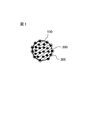
- FIG. 1 is a cross-sectional view schematically showing a negative electrode active material according to the present invention.
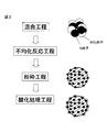
- FIG. 2 is a flowchart showing a manufacturing process of the negative electrode active material according to the present invention.
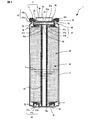
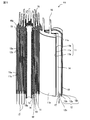
- FIG. 3 is a cross-sectional view of a cylindrical lithium ion secondary battery.
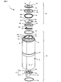
- FIG. 4 is an exploded perspective view of a cylindrical lithium ion secondary battery.
- FIG. 5 is an exploded cross-sectional perspective view of the power generation element of the cylindrical lithium ion secondary battery.
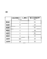
- FIG. 6 is a table showing the SiO 2 layer thickness of the negative electrode active material and the capacity retention rate of the lithium secondary battery for the examples and comparative examples.
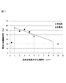
- FIG. 7 is a graph showing the relationship between the thickness of the SiO 2 layer and the capacity retention ratio.
- FIG. 1 is a cross-sectional view schematically showing a negative electrode active material according to the present invention.
- the negative electrode active material according to the present invention has a structure in which Si particles 100 are dispersed in SiO 2 particles 200. Most of the Si particles 100 are dispersed inside the SiO 2 particles 200, but some of the Si particles 100 protrude from the surface of the SiO 2 particles 200.
- a SiO2 layer 300 is provided on the surface of the protruding Si particles 1. The thickness of the SiO2 layer 300 is 1 nm or more and 9 nm or less.
- the Si particles serve as an active material.
- the lithium ion secondary battery is configured in such a state that the Si particles are not covered with the SiO 2 layer and are in direct contact with the electrolytic solution, the electrolytic solution is decomposed on the surface of the Si particles by the electric potential and deposited as a salt. As the electrolytic solution decomposes, the resistance of the lithium ion secondary battery increases, and as a result, the battery capacity decreases. That is, a decrease in capacity maintenance rate (cycle deterioration) occurs.
- the negative electrode active material according to the present invention since the surface of the Si particles 100 protruding from the surface of the SiO2 particles 200 is covered with the SiO2 layer 300, the Si particles and the electrolytic solution are not in direct contact.
- the thickness of the SiO2 layer 300 covering the surface of the Si particle 100 protruding from the surface of the SiO2 particle 200 is less than 1 nm, the coating is not sufficient, so that the effect of suppressing the decomposition of the electrolytic solution and the volume change of the Si particle are suppressed. The effect to do is small.
- the thickness of the SiO2 layer 300 exceeds 9 nm the effect of suppressing the decomposition of the electrolytic solution is enhanced, but the reaction between lithium ions and Si is inhibited, so that the capacity retention rate of the battery is lowered.
- the particle diameter of the SiO 2 particles 200 is preferably 1 to 30 ⁇ m, and more preferably 3 to 10 ⁇ m.
- the particle diameter of the SiO2 particles 200 can be adjusted as appropriate by changing the manufacturing conditions. When the particle diameter of the SiO2 particles 200 is less than 1 ⁇ m, the aggregation of the SiO2 particles becomes severe and the handling of the particles should be difficult. Moreover, when the particle diameter of SiO2 particle
- the particle size of the Si particles 100 is preferably 1 to 100 nm, and more preferably 3 to 20 nm. Further, the ratio of the mass of the Si particles to the mass of the whole negative electrode active material is preferably 40 to 80% by mass. When Si particles are dispersed so as to have such a ratio, the number of Si particles protruding from the surface of the SiO2 particles increases. If the surface of the Si particles is not covered with the SiO2 layer, as already described, the amount of the electrolytic solution to be decomposed increases and the capacity retention rate of the battery decreases.
- the negative electrode active material of the present invention since the Si particles protruding from the surface of the SiO2 particles are covered with the SiO2 layer, the decomposition of the electrolytic solution is suppressed, and the capacity retention rate of the battery can be kept high. Since the ratio of Si particles can be increased, the capacity of the battery can be increased.
- FIG. 2 is a flowchart showing the manufacturing process of the negative electrode active material according to the present invention.
- the manufacturing process of the negative electrode active material according to the present invention includes a mixing step of mixing Si particles and SiO2 particles, a disproportionation reaction step of aggregating SiO2 particles and simultaneously growing Si crystals, and a disproportionation reaction step. It comprises a pulverizing step of pulverizing the SiO2 particles in which Si crystal particles are dispersed, and an oxidation treatment step of oxidizing the surface of Si exposed on the surface of the pulverized particles and covering it with an SiO2 layer.
- Si particles and SiO2 particles are put into a ball mill drum at an appropriate ratio.
- the drum is rotated at a rotational speed of about 150 rpm for a predetermined time, and Si particles and SiO2 particles are mixed to prepare mixed particles.
- the Si-dispersed particles are again put into the drum of the ball mill, and the drum is rotated at a rotation speed of about 500 rpm for a predetermined time. Thereby, the Si dispersed particles are pulverized to obtain pulverized Si dispersed particles having a desired size.
- the negative electrode active material according to the present invention is manufactured.
- the value of x is preferably 0.2 ⁇ x ⁇ 1.2.
- the thickness of the SiO 2 layer covering the exposed surface of the Si particles can be appropriately adjusted depending on the temperature and time, which are conditions for the oxidation treatment. In this oxidation treatment step, the equipment used in the disproportionation reaction step which is the previous step can be used. Further, no special material for covering the surface of the exposed Si particles is required. Therefore, it is not necessary to introduce a large-scale manufacturing facility for covering the surface of the Si particles, and as a result, the manufacturing cost should be reduced.
- a negative electrode is produced using the negative electrode active material according to the present invention produced by the above steps.
- the negative electrode is produced by forming a negative electrode mixture layer by applying a negative electrode mixture comprising a negative electrode active material and a negative electrode binder to the surface of a copper foil as a negative electrode plate.
- a conductive agent may be added to the negative electrode mixture as necessary for the purpose of increasing the conductivity of the negative electrode mixture layer.
- carbon materials such as carbon black, graphite, carbon fiber, and metal carbide can be used. These materials may be used alone or in combination of two or more.
- the negative electrode binder it is preferable to use styrene-butadiene rubber (SBR) and carboxymethyl cellulose (CMC), and the ratio of the negative electrode binder is about 98: 1: 1 by mass ratio of the negative electrode active material, SBR, and CMC. Preferably there is.
- SBR styrene-butadiene rubber
- CMC carboxymethyl cellulose
- any material other than the above SBR and CMC can be used as long as the negative electrode active material and the negative electrode plate are brought into close contact with each other.
- a homopolymer such as vinylidene fluoride, tetrafluoroethylene, acrylonitrile, ethylene oxide, or a copolymer thereof can be used.
- FIGS. 3 is a cross-sectional view showing an embodiment of a cylindrical lithium ion secondary battery
- FIG. 4 is an exploded perspective view thereof
- FIG. 5 is an exploded cross-sectional perspective view of the power generation element.
- a cylindrical lithium ion secondary battery 1 includes a battery container 4 including a cylindrical battery can 2 having an upper opening and a battery lid 3 that seals the upper portion of the battery can 2. Iron or the like is used as the material of the battery can 2. Inside the battery container 4 are housed each component for power generation described below and a non-aqueous electrolyte 5.
- a groove 2 a protruding inward is formed on the upper end side (opening 2 b side) of the battery can 2.
- a power generation element 10 is disposed inside the battery can 2.
- the power generation element 10 includes a cylindrical shaft core 15 having a hollow portion along the central axis of the battery can 2, and a positive electrode plate and a negative electrode plate wound around the shaft core 15 via a separator.
- a groove 15 a having a diameter larger than that of the hollow portion is formed in the shaft core 15 on the inner side of the upper end portion in the central axis direction (vertical direction in FIG. 3) of the battery can 2.
- a thin cylindrical positive current collector plate 27 is press-fitted into the groove 15a.
- the positive electrode current collector plate 27 includes a disc-shaped base portion 27a, a lower tube portion 27b that protrudes from the base portion 27a toward the shaft core 15 and is press-fitted into the shaft core 15, and an upper tube that protrudes from the base portion 27a toward the battery lid 3 side. Part 27c.
- the positive electrode tab 16 is welded to the upper cylindrical portion 27 c of the positive electrode current collector plate 27.
- the plurality of positive electrode tabs 16 are brought into close contact with the outer peripheral portion of the upper cylindrical portion 27c of the positive electrode current collector plate 27, and the pressing member 28 is wound around the ring shape in a ring shape and temporarily fixed.
- the positive electrode tab 16 is welded to the upper cylindrical portion 27c and the pressing member 28 by ultrasonic welding.
- a step portion 15b having a reduced outer diameter is formed on the outer peripheral portion on the lower end side of the shaft core 15, and a negative electrode current collector plate 21 is press-fitted and fixed to the step portion 15b.
- the negative electrode current collector plate 21 is formed of, for example, a copper alloy.
- An opening 21b for press-fitting into the step portion 15b of the shaft core 15 is formed in the disc-shaped base portion 21a, and an outer peripheral cylindrical portion 21c protruding toward the bottom side of the battery can 2 is formed in the outer peripheral portion. ing.
- an opening 21d (see FIG. 4) for allowing the non-aqueous electrolyte 5 injected into the hollow shaft of the shaft core 15 to permeate the power generation element 10 is formed.
- the negative electrode tab 17 is welded to the outer peripheral cylindrical portion 21 c of the negative electrode current collector plate 21.
- a plurality of negative electrode tabs 17 are brought into close contact with the outer peripheral portion of the outer peripheral cylindrical portion 21c of the negative electrode current collector plate 21, and the holding member 22 is wound around in a ring shape and temporarily fixed.
- the negative electrode tab 17 is welded to the outer peripheral member 21c and the pressing member 22 by welding.
- a connection lead plate 50 is joined to the base portion 21a of the negative electrode current collector plate 21 by ultrasonic welding or the like.
- the connection lead plate 50 is joined to the bottom 2c of the battery can 2 by resistance welding or the like.
- the plurality of positive electrode tabs 16 are welded to the positive electrode current collector plate 27, and the plurality of negative electrode tabs 17 are welded to the negative electrode current collector plate 21, whereby the positive electrode current collector plate 27, the negative electrode current collector plate 21, and the power generation element 10, a power generation unit 20 that is unitized as one unit is configured.
- a power generation unit 20 that is unitized as one unit is configured.
- the non-aqueous electrolyte 5 that is injected into the battery container 4 there is an electric field solution in which a lithium salt is dissolved in a carbonate-based solvent.
- the positive electrode current collector plate 27 is made of, for example, an aluminum-based metal. As shown in FIG. 4, openings 27 d and 27 e are formed in the base portion 27 a of the positive electrode current collector plate 27.
- the opening 27d is an opening for releasing gas generated inside the battery, and the opening 27e is used for inserting an electrode rod (not shown) when welding the connection lead plate 50 to the battery can 2. It is an opening. Specifically, the electrode rod is inserted from the opening 27e, the connection lead plate 50 is pressed against the inner surface of the bottom 2c of the battery can 2 through the hollow portion of the shaft core 15, and the connection lead plate 50 is attached to the battery can 2. Resistance welding.
- the bottom surface of the battery can 2 connected to the negative electrode current collector plate 21 functions as an output terminal when taking out the electric power charged in the power generation element 10 from the battery can 2.
- a flexible connecting member 33 formed by laminating a plurality of aluminum foils is joined to the upper surface of the base portion 27a of the positive electrode current collector plate 27 by welding one end thereof.
- a battery lid unit 30 is disposed on the upper cylindrical portion 27 c of the positive electrode current collector plate 27.
- the battery lid unit 30 includes a ring-shaped insulating plate 34 made of an insulating resin material, a connection plate 35 fitted into the opening 34 a of the insulating plate 34, a diaphragm 37 welded to the connection plate 35, and caulking and welding to the diaphragm 37. It is comprised by the battery cover 3 fixed by.
- the insulating plate 34 has an opening 34a and a side 34b protruding downward.
- the connection member 33 is joined to the lower surface of the connection plate 35 by welding an end portion opposite to one end welded to the upper surface of the base portion 27 a of the positive electrode current collector plate 27.
- the connection plate 35 is made of an aluminum-based metal and has a dish shape in which the center side is gently bent downward. A central portion of the connection plate 35 is thin, and a projection 35a formed in a convex dome shape is provided at the center, and a plurality of openings 35b are formed surrounding the projection 35a. Has been.
- the opening 35b has a function of releasing gas generated inside the battery.
- the protrusion 35 a of the connection plate 35 is joined to the bottom surface of the center portion of the diaphragm 37 by resistance welding or friction stir welding.
- the diaphragm 37 is formed of an aluminum-based metal, and a circular cut 37a is formed at the center of the diaphragm 37 by crushing the upper surface side into a V shape by pressing. The diaphragm 37 is provided for ensuring the safety of the battery, and when the internal pressure of the battery rises due to the gas generated inside the battery, the notch 37a is cleaved by the pressure to release the internal gas. Have.
- the periphery of the diaphragm 37 is fixed to the periphery of the battery lid 3.
- the diaphragm 37 has a side wall 37b whose peripheral edge stands vertically toward the battery lid 3 side (upward).
- the battery lid 3 is accommodated in a space provided above the diaphragm 37 by the side wall 37b, and the battery lid 3 is fixed by bending the side wall 37b to the upper surface side of the battery lid 3 by caulking.
- the battery lid 3 is made of iron such as carbon steel, and nickel plating is applied to both the front and back surfaces.
- the battery lid 3 includes a disc-shaped peripheral edge 3 a that contacts the diaphragm 37 and a cylindrical portion 3 b that protrudes upward from the peripheral edge 3 a.
- An opening 3c is formed at the center of the cylindrical portion 3b. The opening 3c is for releasing gas to the outside of the battery when the cut 37a of the diaphragm 37 is cleaved by the gas pressure generated inside the battery.
- the battery lid 3 acts as an output end when taking out the electric power stored in the power generation element 10 from the battery can 2.
- the caulked portion between the diaphragm 37 and the battery lid 3 is covered with a gasket 43 made of an insulating member.
- the gasket 43 has a shape having an outer peripheral wall portion 43b formed to rise substantially vertically upward at the peripheral side edge of the ring-shaped base portion 43a.
- the outer peripheral wall portion 43b is bent inward together with the battery can 2 by a press or the like, and the diaphragm 37 and the battery are formed by the base portion 43a and the outer peripheral wall portion 43b.
- the caulking portion of the lid 3 is sandwiched.
- the battery lid unit 30 in which the battery lid 3, the diaphragm 37, the insulating plate 34, and the connection plate 35 are integrated is configured.
- a specific material of the gasket 43 rubber is used, but fluorine resin may be used.
- the power generation element 10 is configured by winding a positive electrode plate 11, a negative electrode plate 12, a first separator 13, and a second separator 14 around an axis 15.
- the first separator 13 and the second separator 14 are made of, for example, an insulating polyethylene porous body having a thickness of 40 ⁇ m.
- the shaft core 15 is wound from the inner periphery several times in a state where the first separator 13 and the second separator 14 are overlapped.
- FIG. 5 for the sake of brevity, a state where only one round is wound is shown. From this position, the second separator 14, the negative electrode plate 12, the first separator 13, and the positive electrode plate 11 are wound in a stacked state several times so that they are in this order. 13, the negative electrode plate 12, the second separator 14, and the positive electrode plate 11 are wound in this order. Therefore, the negative electrode plate 12 should be wound one more turn than the positive electrode plate 11.
- the end of the first separator 13 at the outermost periphery is fixed with an adhesive tape 19.
- the positive electrode plate 11 is formed by applying a positive electrode mixture on both surfaces of an elongated positive electrode metal foil 11a made of aluminum to form a positive electrode processing portion 11b.
- a positive electrode mixture untreated portion 11c in which the positive electrode metal foil 11a is exposed without being coated with the positive electrode mixture is provided on the upper side edge of the positive electrode metal foil 11a.
- a plurality of positive electrode tabs 16 for protruding upward along the axis of the shaft core 15 are formed integrally with the positive electrode mixture untreated portion 11c at equal intervals.
- the positive electrode mixture is composed of a positive electrode active material, a positive electrode conductive material, and a positive electrode binder.
- the positive electrode active material include lithium oxides of transition metals such as cobalt, manganese, and nickel.
- the positive electrode binder include polyvinylidene fluoride (PVDF) and fluororubber.
- the positive electrode mixture slurry prepared by dispersing the positive electrode mixture in a solvent was applied to both sides of an aluminum foil having a thickness of 20 ⁇ m as the positive electrode metal foil 11a to a uniform thickness, and the solvent was dried. Cut to desired shape.
- the coating thickness of the positive electrode mixture is, for example, about 40 ⁇ m on one side.
- a plurality of positive electrode tabs 16 are also formed at the same time. The shapes of the plurality of positive electrode tabs 16 are substantially the same.
- coating a positive mix to the positive electrode metal foil 11a a roll coating method, a slit die coating method, etc. are mentioned.
- the negative electrode plate 12 is formed by applying a negative electrode mixture on both surfaces of a long negative electrode metal foil 12a made of copper foil to form a negative electrode processing portion 12b.
- a negative electrode mixture untreated portion 12c in which the negative electrode metal foil 12a is exposed without being coated with the negative electrode mixture is provided on the lower side edge of the negative electrode metal foil 12a.
- a plurality of negative electrode tabs 17 for protruding downward in the direction opposite to the positive electrode tab 16 along the axis of the shaft core 15 are integrated with the negative electrode mixture untreated portion 12c at equal intervals. Is formed.
- the negative electrode mixture is composed of a negative electrode active material, a negative electrode binder, and a thickener.
- An example of the negative electrode active material is graphite carbon.
- a negative electrode mixture slurry prepared by dispersing a negative electrode mixture in a solvent is applied to both surfaces of a rolled copper foil having a thickness of 10 ⁇ m as the negative electrode metal foil 12a, and the solvent is added. After drying, it is cut into a desired shape by a press.
- the coating thickness of the negative electrode mixture is, for example, about 40 ⁇ m on one side.
- a plurality of negative electrode tabs 17 are also formed at the same time.
- Both the widths of the first separator 13 and the second separator 14 are larger than the widths of the positive electrode plate 11 and the negative electrode plate 12. Further, the width and length of the negative electrode processing portion 12b of the negative electrode plate 12 are larger than the width and length of the positive electrode processing portion 11b of the positive electrode plate 11, respectively. That is, the entire region of the negative electrode metal foil 12a corresponding to the positive electrode processing portion 11b is covered with the negative electrode processing portion 12b.
- the reason for this configuration is as follows. In a lithium ion secondary battery, lithium which is a positive electrode active material is ionized, penetrates the separator, and is occluded by the negative electrode active material.
- Example 1 The negative electrode active material according to the present invention was prepared by the following procedure. Si particles having a mean diameter of 4 ⁇ m and SiO2 particles are charged into a drum of a ball mill so as to have a molar ratio of 1: 1, and the drum is rotated at a rotation speed of 150 rpm to mix Si particles and SiO2 particles. Mixed particles were prepared. The mixed particles are heated to 1000 ° C. in an argon gas atmosphere and maintained in that state for 3 hours to generate a disproportionation reaction. In the aggregated SiO 2, Si dispersed particles in which crystal-grown Si particles are dispersed are obtained. Prepared.
- the Si-dispersed particles were again put into a drum of a ball mill, and the drum was rotated at a rotation speed of 500 rpm to pulverize the Si-dispersed particles to prepare pulverized Si-dispersed particles.
- oxidation treatment is performed by holding the pulverized Si dispersed particles in the atmosphere at a temperature of 300 ° C. for 15 minutes, and the surface of the Si particles protruding and exposed on the surface of the Si dispersed particles is oxidized to form a SiO 2 layer.
- the negative electrode active material of Example 1 was obtained. It was 1 nm when the thickness of the said SiO2 layer was measured.
- the thickness of the SiO2 layer is measured by cutting the oxidized Si dispersed particles by FIB (focused ion beam) to form a cross section, and observing the cross section with a STEM (scanning transmission electron microscope). It went by.
- Example 2 A negative electrode active material was prepared in the same procedure as in Example 1 except that the oxidation treatment in the atmosphere was held at 300 ° C. for 1 hour. The measurement result of the SiO2 layer thickness was 2 nm.
- Example 3 A negative electrode active material was prepared in the same procedure as in Example 1 except that the oxidation treatment in the atmosphere was held at 400 ° C. for 1 hour. The measurement result of the SiO2 layer thickness was 3 nm.
- Example 4 A negative electrode active material was prepared in the same procedure as in Example 1 except that the oxidation treatment in the atmosphere was held at 400 ° C. for 3 hours. The measurement result of the SiO2 layer thickness was 4 nm.
- Example 5 A negative electrode active material was prepared in the same procedure as in Example 1 except that the oxidation treatment in the atmosphere was held at 400 ° C. for 5 hours. The measurement result of the SiO2 layer thickness was 5 nm.
- Example 6 A negative electrode active material was prepared in the same procedure as in Example 1 except that the oxidation treatment in the atmosphere was held at 500 ° C. for 1 hour. The measurement result of the SiO2 layer thickness was 4 nm.
- Example 1 A negative electrode active material was prepared in the same procedure as in Example 1 except that the oxidation treatment in the atmosphere was not performed.
- the measurement result of the SiO2 layer thickness was 0.3 nm.
- Example 2 A negative electrode active material was prepared in the same procedure as in Example 1 except that the oxidation treatment in the atmosphere was held at 1000 ° C. for 3 hours. The measurement result of the SiO2 layer thickness was 10 nm.
- a negative electrode was produced using the negative electrode active materials prepared in Examples 1 to 6 and Comparative Examples 1 and 2, and a lithium secondary battery having the structure shown in FIG. 3 was produced using the negative electrode.
- the capacity retention rate of the lithium ion secondary battery was measured by the following procedure. First, the lithium secondary battery was repeatedly charged and discharged at a temperature of 25 ° C. The charging conditions were constant current and constant voltage charging for 4 hours with a charging current equivalent to 0.5 C and an upper limit voltage of 4.2 V. The discharge conditions were a discharge current corresponding to 0.5 C and a constant current discharge with a lower limit voltage of 2.5 V. In the charge / discharge, the discharge capacity at the first cycle was measured, and the ratio of the discharge capacity at the 20th cycle to the discharge capacity (discharge capacity at the 20th cycle / discharge capacity at the 1st cycle) was defined as the capacity retention rate. The cycle characteristics were evaluated based on the capacity retention rate.
- FIG. 7 is a graph plotting the relationship between the thickness of the SiO 2 layer shown in FIG. 6 and the capacity retention rate of the battery.
- the thickness of the SiO 2 layer coated with Si particles was 1 nm.
- the capacity retention rate was 55%, the highest value.
- the capacity retention rate gradually decreased as the thickness of the SiO 2 layer increased, and decreased to 20% in Comparative Example 2 where the thickness of the SiO 2 layer was 10 nm. From these results, it can be seen that when the thickness of the SiO 2 layer is 1 to 9 nm, the capacity retention rate of the battery can be 25% or more, which is preferable. Further, it can be seen that when the thickness of the SiO 2 layer is 1 to 5 nm, the capacity retention rate of the battery can be 40% or more, which is more preferable.
- the capacity maintenance rate is 23%, and the capacity maintenance of the lithium ion secondary batteries of Examples 1 to 6 is maintained. It can be seen that it is significantly lower than the rate.
Landscapes
- Chemical & Material Sciences (AREA)
- Engineering & Computer Science (AREA)
- Materials Engineering (AREA)
- Chemical Kinetics & Catalysis (AREA)
- Electrochemistry (AREA)
- General Chemical & Material Sciences (AREA)
- Manufacturing & Machinery (AREA)
- Battery Electrode And Active Subsutance (AREA)
Abstract
リチウムイオン二次電池用負極活物質であって、負極活物質粒子はSi粒子とSiO2粒子との凝集体からなり、凝集体は、SiO2内に複数のSi粒子が分散されて構成され、複数のSi粒子には、表面の一部がSiO2の表面から突出した突出部を有するSi粒子を含まれ、突出部の表面にはSiO2層が形成され、SiO2層の厚さは、1nm以上、かつ、9nm以下、である。
Description
本発明は、リチウムイオン二次電池用負極活物質、リチウムイオン二次電池、およびリチウムイオン二次電池用負極活物質の製造方法に関する。
近年、高エネルギー密度を有する二次電池としてリチウムイオン二次電池が着目され、その研究開発及び商品化が急速に進められている。その結果、携帯電話やノートパソコン向け等の小型民生用機器にリチウムイオン二次電池が幅広く普及している。さらに、地球温暖化、燃料枯渇、脱原子力発電等の観点から、家庭用、産業用、車載用等の蓄電池として、従来よりも高容量な大型のリチウムイオン二次電池が求められている。リチウムイオン二次電池の高容量化のための一つの方策として、負極活物質材料にSi(ケイ素)を用いることが知られている。しかし、Siは、充放電による体積変化が黒鉛の4倍もあるため、充放電に伴って負極の崩壊が発生すること、また、電解液が分解され易くサイクル特性が劣る等の課題がある。
特許文献1には、Siの微結晶がSi系化合物に分散した構造を有する粒子を負極活物質として用いた非水電解質二次電池について開示されている。また、特許文献2には、SiOx(0.3≦x≦1.6)で表されるSi酸化物からなる粒状体と、該粒状体の表面を被覆する炭化ケイ素被膜と、で構成した負極活物質を用いたリチウムイオン二次電池について開示されている。
しかし、特許文献1に開示された構造を有する粒子を負極活物質として用いたリチウムイオン二次電池においては、粒子表面に露出したSiが電解液を分解するため、容量維持率が低い(サイクル特性が悪い)という問題がある。また、特許文献2に開示された構成の負極活物質を作製するためには、CVD装置等の高価で大がかりな製造装置が必要となるため、製造コストが高くなるという問題がある。
本発明は、容量維持率の優れたリチウムイオン二次電池用負極活物質を、高価で大がかりな製造設備を用いずに製造コストを抑えて提供することを目的とする。
本発明のリチウムイオン二次電池用負極活物質は、Si粒子とSiO2粒子との凝集体からなり、該凝集体は、SiO2内に複数のSi粒子が分散されて構成され、複数のSi粒子には、表面の一部がSiO2の表面から突出した突出部を有するSi粒子を含まれ、突出部の表面にはSiO2層が形成され、SiO2層の厚さは、1nm以上、かつ、9nm以下、である。
本発明によれば、容量維持率の優れたリチウムイオン二次電池用負極活物質を、高価で大がかりな製造設備を必要とせずに製造コストを抑えて提供することができる。
以下、図面を参照して、本発明について説明する。図1は、本発明に係る負極活物質を模式的に示す断面図である。図1に示した通り、本発明に係る負極活物質は、SiO2粒子200の内部にSi粒子100が 分散された構造を有している。Si粒子100の多くはSiO2粒子200の内部に分散されているが、一部のSi粒子100はSiO2粒子200の表面から突出している。この突出したSi粒子1の表面にはSiO2層300が設けられている。SiO2層300の厚さは1nm以上、かつ、9nm以下である。ここで、Si粒子は活物質の作用を担っている。もし、Si粒子がSiO2層により被覆されずに電解液に直接接する状態でリチウムイオン二次電池を構成した場合、電位によりSi粒子表面で電解液が分解し塩として析出する。電解液が分解するに従って、リチウムイオン二次電池の抵抗は上昇し、その結果、電池容量が低下する。すなわち、容量維持率の低下(サイクル劣化)が起こる。本発明に係る負極活物質においては、SiO2粒子200の表面から突出したSi粒子100の表面はSiO2層300により被覆されているため、Si粒子と電解液が直接触れることがない。その結果、電解液が塩として析出することを抑制し、電池の容量維持率を高い状態に維持することができる。また、Si粒子をSiO2層により被覆することで、充放電の際のSi粒子の体積変化を抑制することができる。
SiO2粒子200の表面から突出したSi粒子100の表面を被覆するSiO2層300の厚さが1nm未満の場合、被覆が十分でないため、電解液の分解を抑制する効果やSi粒子の体積変化を抑制する効果が小さい。一方、SiO2層300の厚さが9nmを超える場合、電解液の分解を抑制する効果は高くなるが、リチウムイオンとSiの反応が阻害されるため、電池の容量維持率が低下する。
SiO2粒子200の粒径は、1~30μmであることが好ましく、3~10μmであることがより好ましい。SiO2粒子200の粒径は、製造条件を変更することで適宜調節できる。SiO2粒子200の粒径が、1μm未満の場合、SiO2粒子の凝集が激しくなり、粒子の取り扱いが難しくなる 。また、SiO2粒子の粒径が30μmを超える場合、SiO2粒子の中心に近い部分のSi粒子までの距離が大きくなる。SiO2の導電性は低いので、このようにSiO2粒子の中心に近い部分のSi粒子は電池の充放電に関与できなくなる 。この結果、電池の初期容量は低下する。
Si粒子100の粒径は、1~100nmであることが好ましく、3~20nmであることがより好ましい。また、負極活物質全体の質量に対するSi粒子の質量の割合は、40~80質量%であることが好ましい。このような比率となるようにSi粒子を分散させると、SiO2粒子表面から突出するSi粒子の数は多くなる。もし、Si粒子の表面がSiO2層により被覆されていない場合には、既に説明したように、分解される電解液の量が多くなり電池の容量維持率は低下する。しかし、本発明の負極活物質においては、SiO2粒子表面から突出したSi粒子はSiO2層により被覆されているため、電解液の分解は抑制され、電池の容量維持率を高く保つことができ、また、Si粒子の比率が大きくできるので、電池の容量を大きくすることができる。
図2は、本発明に係る負極活物質の製造工程を示すフローチャートである。本発明に係る負極活物質の製造工程は、Si粒子とSiO2粒子とを混合する混合工程、SiO2粒子を凝集させ、同時にSi結晶を成長させる不均化反応工程、不均化反応工程により内部にSi結晶粒子が分散したSiO2粒子を粉砕する粉砕工程、および、粉砕された粒子の表面に露出したSiの表面を酸化してSiO2層で被覆する酸化処理工程からなる。
(混合工程)
ボールミルのドラムにSi粒子とSiO2粒子とを適当な比率で投入する。ドラムを約150rpmの回転速度で所定時間回転させ、Si粒子とSiO2粒子とを混合して混合粒子を調製する。
ボールミルのドラムにSi粒子とSiO2粒子とを適当な比率で投入する。ドラムを約150rpmの回転速度で所定時間回転させ、Si粒子とSiO2粒子とを混合して混合粒子を調製する。
(不均化反応工程)
上記混合粒子を、アルゴンガス雰囲気中で1000℃まで昇温後、3時間保持する。これにより不均化反応が起こり、凝集したSiO2中に、結晶成長したSi粒子が分散したSi分散粒子が得られる。
上記混合粒子を、アルゴンガス雰囲気中で1000℃まで昇温後、3時間保持する。これにより不均化反応が起こり、凝集したSiO2中に、結晶成長したSi粒子が分散したSi分散粒子が得られる。
(粉砕工程)
上記Si分散粒子を再びボールミルのドラムに投入し、ドラムを約500rpmの回転速度で所定時間回転させる。これにより、上記Si分散粒子を粉砕して所望の大きさの粉砕Si分散粒子を得る。
上記Si分散粒子を再びボールミルのドラムに投入し、ドラムを約500rpmの回転速度で所定時間回転させる。これにより、上記Si分散粒子を粉砕して所望の大きさの粉砕Si分散粒子を得る。
(酸化処理工程)
上記粉砕Si分散粒子の表面には結晶化したSi粒子が突出して露出した部分が存在する。この粉砕Si分散粒子を、高温雰囲気で酸化処理することで、表面に突出し露出したSi粒子の表面を酸化してSiO2層を形成する。このようにして本発明に係る負極活物質は製造される。
上記粉砕Si分散粒子の表面には結晶化したSi粒子が突出して露出した部分が存在する。この粉砕Si分散粒子を、高温雰囲気で酸化処理することで、表面に突出し露出したSi粒子の表面を酸化してSiO2層を形成する。このようにして本発明に係る負極活物質は製造される。
本発明に係る負極活物質の組成をSiOxで表した場合、xの値は0.2≦x≦1.2であることが好ましい。なお、露出したSi粒子の表面を被覆するSiO2層の厚さは、酸化処理する際の条件である温度および時間により適宜調節することができる。この酸化処理工程では、その前工程である不均化反応工程に用いた設備を用いることができる。また、露出したSi粒子の表面を被覆するための材料を特別には必要としない。従って、Si粒子の表面を被覆するために大がかりな製造設備を導入する必用がなく、その結果、製造コストを抑えることができる 。
(負極の作製)
以上の工程により製造された本発明に係る負極活物質を用いて負極を作製する。負極は、負極板としての銅箔表面に、負極活物質と負極バインダからなる負極合剤を塗布することにより、負極合剤層を形成して作製される。負極合剤には、負極合剤層の導電性を高める目的で、必要に応じて導電剤を添加してもよい。導電剤としては、カーボンブラック、グラファイト、カーボンファイバー及び金属炭化物等のカーボン材料が使用可能である。これらの材料は、それぞれ単独で用いても、あるいは、2種類以上を混合して用いてもよい。
以上の工程により製造された本発明に係る負極活物質を用いて負極を作製する。負極は、負極板としての銅箔表面に、負極活物質と負極バインダからなる負極合剤を塗布することにより、負極合剤層を形成して作製される。負極合剤には、負極合剤層の導電性を高める目的で、必要に応じて導電剤を添加してもよい。導電剤としては、カーボンブラック、グラファイト、カーボンファイバー及び金属炭化物等のカーボン材料が使用可能である。これらの材料は、それぞれ単独で用いても、あるいは、2種類以上を混合して用いてもよい。
負極バインダとしては、スチレン-ブタジエンゴム(SBR)とカルボキシメチルセルロース(CMC)を用いることが好ましく、負極バインダの比率は、負極活物質、SBR、およびCMCの質量比で、98:1:1程度であることが好ましい。なお、負極バインダとしては、負極活物質と負極板を密着させるものであれば、上記のSBRやCMC以外の材料でも使用可能である。例えば、フッ化ビニリデン、四フッ化エチレン、アクリロニトリル、エチレンオキシド等の単独重合体、あるいはこれらの共重合体等も使用可能である。
次に、本発明に係る負極活物質を負極に適用したリチウムイオン二次電池について、図3~図5を参照して説明する。図3は、円筒形リチウムイオン二次電池の一実施の形態を示す断面図、図4は、その分解斜視図、図5は、その発電要素の分解断面斜視図である。円筒形リチウムイオン二次電池1は、上部が開口された円筒形の電池缶2と電池缶2の上部を封口する電池蓋3とで構成された電池容器4を有する。電池缶2の材料には鉄等が用いられる。電池容器4の内部には、次に説明する発電用の各構成部材と非水電解液5が収容されている。
電池缶2の上端側(開口部2b側)には、内側に突き出した溝2aが形成されている。電池缶2の内部には発電要素10が配置される。発電要素10は、電池缶2の中心軸に沿って中空部を有する円筒形の軸芯15、および軸芯15の周囲にセパレータを介して捲回された正極板と負極板で構成される。軸芯15には、電池缶2の中心軸方向(図3の上下方向)の上端部の内側に中空部に比べて直径の大きな溝15aが形成されている。溝15aには薄い円筒状の正極集電板27が圧入されている。正極集電板27は、円板状の基部27aと、基部27aから軸芯15側に突出して軸芯15に圧入される下部筒部27bと、基部27aから電池蓋3側に突き出た上部筒部27cとを有する。
正極集電板27の上部筒部27cには正極タブ16が溶接されている。具体的な溶接方法としては、複数の正極タブ16を、正極集電板27の上部筒部27cの外周部に密着させた状態として、その上から押え部材28をリング状に巻き付けて仮固定し、その状態で超音波溶接により、正極タブ16を上部筒部27cおよび押え部材28に溶接する。
軸芯15の下端側外周部には、外径を小さくした段部15bが形成され、段部15bには負極集電板21が圧入され固定されている。負極集電板21は、例えば、銅合金により形成される。円板状の基部21aには、軸芯15の段部15bに圧入するための開口部21bが形成され、外周部には、電池缶2の底部側に向かって突き出す外周筒部21cが形成されている。基部21aには、軸芯15の中空軸に注入された非水電解液5を発電要素10に浸透させるための開口部21d(図4参照)が形成されている。
負極集電板21の外周筒部21cには負極タブ17が溶接されている。具体的な溶接方法としては、複数の負極タブ17を、負極集電板21の外周筒部21cの外周部に密着させ、押え部材22をリング状に巻き付けて仮固定し、この状態で超音波溶接により、負極タブ17を外周部材21cおよび押え部材22に溶接する。負極集電板21の基部21aには、接続リード板50が超音波溶接等により接合されている。接続リード板50は、抵抗溶接等により電池缶2の底部2cに接合されている。
複数の正極タブ16が正極集電板27に溶接され、また、複数の負極タブ17が負極集電板21に溶接されることにより、正極集電板27、負極集電板21、および発電要素10により、一体的にユニット化された発電ユニット20が構成される。電池容器4の内部に注入される非水電解液5の一例として、リチウム塩がカーボネート系溶媒に溶解した電界液が挙げられる。
正極集電板27は、例えば、アルミニウム系金属により形成されている。図4に示す通り、正極集電板27の基部27aには、開口部27dおよび27eが形成されている。開口部27dは電池内部で発生するガスを放出するための開口部であり、開口部27eは接続リード板50を電池缶2に溶接する際に、電極棒(図示せず)を挿通するための開口部である。具体的には、電極棒を開口部27eから差し込み、軸芯15の中空部を通してその先端部で接続リード板50を電池缶2の底部2cの内面に押し付け、接続リード板50を電池缶2に抵抗溶接する。負極集電板21に接続されている電池缶2の底面は、発電要素10に充電された電力を電池缶2から取り出す際の出力端子として作用する。正極集電板27の基部27aの上面には、複数のアルミニウム箔が積層されて構成されたフレキシブルな接続部材33が、その一端を溶接されて接合されている。
正極集電板27の上部筒部27c上には、電池蓋ユニット30が配置されている。電池蓋ユニット30は、絶縁性樹脂材料によるリング形状の絶縁板34、絶縁板34の開口部34aに嵌入された接続板35、接続板35に溶接されたダイアフラム37、およびダイアフラム37にかしめと溶接により固定された電池蓋3により構成される。絶縁板34は、開口部34aおよび下方に突出する側部34bを有している。接続板35の下面には、接続部材33が、正極集電板27の基部27aの上面に溶接された一端とは反対側の端部が溶接されることで接合されている。
接続板35は、アルミニウム系金属で形成され、中央側がゆるやかに下方に撓んだ皿形に形成されている。接続板35の中央部は厚さが薄く、その中心部には上方に凸状のドーム形に形成された突起部35aが設けられており、突起部35aを囲んで複数の開口部35bが形成されている。開口部35bは、電池内部に発生するガスを放出する機能を有している。接続板35の突起部35aはダイアフラム37の中央部の底面に抵抗溶接または摩擦攪拌接合により接合されている。ダイアフラム37はアルミニウム系金属で形成され、ダイアフラム37の中央部には、プレスにより上面側をV字形状に押し潰して薄肉部分とした円形の切込み37aが形成されている。ダイアフラム37は、電池の安全性確保のために設けられており、電池内部で発生したガスにより電池の内部圧力が上昇した場合、その圧力により切込み37aが開裂して内部のガスを放出する機能を有する。
ダイアフラム37は、周縁部が電池蓋3の周縁部に固定されている。ダイアフラム37は、部品段階では、その周縁部が電池蓋3側(上方)に向かって垂直に起立する側壁37bを有している。この側壁37bによりダイアフラム37の上方に設けられた空間に電池蓋3を収容し、側壁37bを電池蓋3の上面側にかしめ加工により屈曲させて電池蓋3を固定する。
電池蓋3は、炭素鋼等の鉄により形成され、表裏両面にニッケルめっきが施されている。電池蓋3は、ダイアフラム37に接触する円盤状の周縁部3aと、周縁部3aから上方に突出する筒部3bからなる。筒部3bの中央部には開口部3cが形成されている。開口部3cは、電池内部に発生するガス圧によりダイアフラム37の切込み37aが開裂した際、ガスを電池外部に放出させるためのものである。電池蓋3は、発電要素10に蓄電された電力を電池缶2から取り出す際の出力端として作用する。
ダイアフラム37と電池蓋3とのかしめ部は、絶縁部材からなるガスケット43により覆われている。ガスケット43は、部品段階では、リング状の基部43aの周側縁に、上方にほぼ垂直に起立して形成された外周壁部43bを有する形状を有している。ガスケット43によりダイアフラム37と電池蓋3とのかしめ部を覆うには、プレス等により、電池缶2と共に外周壁部43bを内側に屈曲させて、基部43aと外周壁部43bにより、ダイアフラム37と電池蓋3のかしめ部を挟み込む。これにより、電池蓋3、ダイアフラム37、絶縁板34、および接続板35が一体となった電池蓋ユニット30が構成される。ガスケット43の具体的な材料としては、ゴムを使用しているが、フッ素系樹脂を用いてもよい。
次に、図5を用いて発電要素10の構造について説明する。発電要素10は、軸芯15の周囲に、正極板11、負極板12、第1のセパレータ13、および第2のセパレータ14が捲回されて構成される。第1のセパレータ13および第2のセパレータ14は、例えば、厚さ40μmの絶縁性のポリエチレン製多孔質体からなる。
軸芯15には内周から、第1のセパレータ13と第2のセパレータ14が重ねられた状態で数周捲回されている。なお、図5においては簡潔に示すために、1周だけ捲回した状態が示されている。この位置から、第2のセパレータ14、負極板12、第1のセパレータ13、正極板11の順となるように、これらを重ねた状態で数回捲回され、外周側から、第1のセパレータ13、負極板12、第2のセパレータ14、正極板11の順となるように捲回されている。従って、負極板12は正極板11より1周多く捲回されている 。最外周における第1のセパレータ13の終端は接着テープ19により固定される 。
正極板11は、アルミニウムからなる長尺形状の正極金属箔11aの両面に正極合剤が塗布されることで正極処理部11bが形成されたものである。正極金属箔11aの上方側の側縁には正極合剤が塗布されずに正極金属箔11aが露出した正極合剤未処理部11cが設けられている。この正極合剤未処理部11cには、軸芯15の軸に沿って上方に突き出すための複数の正極タブ16が等間隔に正極合剤未処理部11cと一体的に形成されている。
正極合剤は、正極活物質と正極導電材と正極バインダとからなる。正極活物質としては、コバルト、マンガン、ニッケル等の遷移金属のリチウム酸化物が挙げられる。また、正極バインダとしては、ポリフッ化ビニリデン(PVDF)やフッ素ゴム等が挙げられる。
正極合剤を溶媒に分散させて調製した正極合剤スラリーを、正極金属箔11aとしての厚さ20μmのアルミニウム箔の両面に均一な厚さに塗布し、溶媒を乾燥させた後、プレス機により所望の形状に裁断する。正極合剤の塗布厚さは、例えば片面約40μmである。正極金属箔11aをプレス機により裁断する際、複数の正極タブ16も同時に形成する。複数の正極タブ16の形状は実質的に同一である。なお、正極合剤を正極金属箔11aに塗布する方法としては、ロール塗工法、スリットダイ塗工法等が挙げられる。
負極板12は、銅箔からなる長尺形状の負極金属箔12aの両面に負極合剤が塗布されることで負極処理部12bが形成されたものである。負極金属箔12aの下方側の側縁には負極合剤が塗布されずに負極金属箔12aが露出した負極合剤未処理部12cが設けられている。この負極合剤未処理部12cには、軸芯15の軸に沿って正極タブ16とは反対方向の下方に突き出すための複数の負極タブ17が等間隔に負極合剤未処理部12cと一体的に形成されている。
負極合剤は、負極活物質と負極バインダと増粘剤とからなる。負極活物質としては、黒鉛炭素が挙げられる。負極を作製するには、負極合剤を溶媒に分散させて調製した負極合剤スラリーを、負極金属箔12aとしての厚さ10μmの圧延銅箔の両面に均一な厚さに塗布し、溶媒を乾燥させた後、プレス機により所望の形状に裁断する。負極合剤の塗布厚さは例えば、片面約40μmである。負極金属箔12aをプレスにより裁断する際、複数の負極タブ17も同時に形成する。複数の負極タブ17の形状はいずれも実質的に同一である。なお、負極合剤を負極金属箔12aに塗布する方法としては、ロール塗工法、スリットダイ塗工法等が挙げられる。
第1のセパレータ13および第2のセパレータ14の幅は共に、正極板11の幅および負極板12のいずれの幅よりも大きい。また、負極板12の負極処理部12bの幅および長さは、それぞれ正極板11の正極処理部11bの幅および長さよりも大きい。すなわち、正極処理部11bに対応する負極金属箔12aの全領域は負極処理部12bで覆われる構成となっている。このような構成とする理由は次の通りである。リチウムイオン二次電池においては、正極活物質であるリチウムがイオン化してセパレータを浸透し、負極活物質に吸蔵される。この際、正極活物質の領域に対応する負極金属箔12aの領域に負極活物質が形成されずに負極金属箔12aが露出していると、負極金属箔12aにリチウムが析出して内部短絡が発生する原因となる。上記のように、少なくとも正極処理部11bに対応する負極金属箔12aの全領域が負極処理部12bで覆われることにより、リチウム析出に伴う内部短絡が発生することを防止できる。次に、本実施形態のリチウムイオン二次電池20の実施例について説明する。
(実施例1)
本発明に係る負極活物質を次の手順により作製した。平均直径が共に4μmのSi粒子とSiO2粒子を1:1のモル比となるようにボールミルのドラムに投入し、ドラムを150rpmの回転速度で回転させて、Si粒子とSiO2粒子とを混合して混合粒子を調製した。この混合粒子をアルゴンガス雰囲気中で1000℃まで昇温し、その状態で3時間保持して不均化反応を発生させ、凝集したSiO2中に、結晶成長したSi粒子が分散したSi分散粒子を調製した。このSi分散粒子を再びボールミルのドラムに投入し、ドラムを500rpmの回転速度で回転させてSi分散粒子を粉砕し、粉砕Si分散粒子を調製した。次に、粉砕Si分散粒子を、大気中で300℃の温度で15分間保持することで酸化処理を行い、Si分散粒子の表面に突出し露出したSi粒子の表面を酸化してSiO2層を形成することで、実施例1の負極活物質を得た。上記SiO2層の厚さを測定したところ1nmであった。なおSiO2層の厚さの測定は、FIB(集束イオンビーム)により、酸化処理後のSi分散粒子に切断加工を施して断面を形成し、その断面をSTEM(走査透過電子顕微鏡)により観察することにより行った。
本発明に係る負極活物質を次の手順により作製した。平均直径が共に4μmのSi粒子とSiO2粒子を1:1のモル比となるようにボールミルのドラムに投入し、ドラムを150rpmの回転速度で回転させて、Si粒子とSiO2粒子とを混合して混合粒子を調製した。この混合粒子をアルゴンガス雰囲気中で1000℃まで昇温し、その状態で3時間保持して不均化反応を発生させ、凝集したSiO2中に、結晶成長したSi粒子が分散したSi分散粒子を調製した。このSi分散粒子を再びボールミルのドラムに投入し、ドラムを500rpmの回転速度で回転させてSi分散粒子を粉砕し、粉砕Si分散粒子を調製した。次に、粉砕Si分散粒子を、大気中で300℃の温度で15分間保持することで酸化処理を行い、Si分散粒子の表面に突出し露出したSi粒子の表面を酸化してSiO2層を形成することで、実施例1の負極活物質を得た。上記SiO2層の厚さを測定したところ1nmであった。なおSiO2層の厚さの測定は、FIB(集束イオンビーム)により、酸化処理後のSi分散粒子に切断加工を施して断面を形成し、その断面をSTEM(走査透過電子顕微鏡)により観察することにより行った。
(実施例2)
大気中での酸化処理を、300℃で1時間保持としたこと以外は、実施例1と同様の手順で負極活物質を作製した。SiO2層厚さの測定結果は2nmであった。
大気中での酸化処理を、300℃で1時間保持としたこと以外は、実施例1と同様の手順で負極活物質を作製した。SiO2層厚さの測定結果は2nmであった。
(実施例3)
大気中での酸化処理を、400℃で1時間保持としたこと以外は、実施例1と同様の手順で負極活物質を作製した。SiO2層厚さの測定結果は3nmであった。
大気中での酸化処理を、400℃で1時間保持としたこと以外は、実施例1と同様の手順で負極活物質を作製した。SiO2層厚さの測定結果は3nmであった。
(実施例4)
大気中での酸化処理を400℃で3時間保持としたこと以外は、実施例1と同様の手順で負極活物質を作製した。SiO2層厚さの測定結果は4nmであった。
大気中での酸化処理を400℃で3時間保持としたこと以外は、実施例1と同様の手順で負極活物質を作製した。SiO2層厚さの測定結果は4nmであった。
(実施例5)
大気中での酸化処理を400℃で5時間保持としたこと以外は、実施例1と同様の手順で負極活物質を作製した。SiO2層厚さの測定結果は5nmであった。
大気中での酸化処理を400℃で5時間保持としたこと以外は、実施例1と同様の手順で負極活物質を作製した。SiO2層厚さの測定結果は5nmであった。
(実施例6)
大気中での酸化処理を500℃で1時間保持としたこと以外は、実施例1と同様の手順で負極活物質を作製した。SiO2層厚さの測定結果は4nmであった。
大気中での酸化処理を500℃で1時間保持としたこと以外は、実施例1と同様の手順で負極活物質を作製した。SiO2層厚さの測定結果は4nmであった。
(比較例1)
大気中での酸化処理を行わなかったこと以外は、実施例1と同様の手順で負極活物質を作製した。SiO2層厚さの測定結果は0.3nmであった。
大気中での酸化処理を行わなかったこと以外は、実施例1と同様の手順で負極活物質を作製した。SiO2層厚さの測定結果は0.3nmであった。
(比較例2)
大気中の酸化処理を1000℃で3時間保持としたこと以外は、実施例1と同様の手順で負極活物質を作製した。SiO2層厚さの測定結果は10nmであった。
大気中の酸化処理を1000℃で3時間保持としたこと以外は、実施例1と同様の手順で負極活物質を作製した。SiO2層厚さの測定結果は10nmであった。
(リチウム二次電池の作製)
実施例1~6および比較例1~2において作成した負極活物質を用いて負極を作製し、この負極を用いて、図3に示す構造のリチウム二次電池を作製した。
実施例1~6および比較例1~2において作成した負極活物質を用いて負極を作製し、この負極を用いて、図3に示す構造のリチウム二次電池を作製した。
(サイクル特性の測定)
上記リチウムイオン二次電池に対して容量維持率を以下の手順により測定した。まず、上記リチウム二次電池に対して、25℃の温度で充電と放電を繰り返した。充電条件は、0.5C相当の充電電流および上限電圧4.2Vにより4時間の定電流定電圧充電とした。また、放電条件は、0.5C相当の放電電流および下限電圧2.5Vの定電流放電とした。上記充放電において、1サイクル目の放電容量を測定し、この放電容量に対する20サイクル目の放電容量の比率(20サイクル目の放電容量/1サイクル目の放電容量)を容量維持率とした。この容量維持率の値によりサイクル特性を評価した。
上記リチウムイオン二次電池に対して容量維持率を以下の手順により測定した。まず、上記リチウム二次電池に対して、25℃の温度で充電と放電を繰り返した。充電条件は、0.5C相当の充電電流および上限電圧4.2Vにより4時間の定電流定電圧充電とした。また、放電条件は、0.5C相当の放電電流および下限電圧2.5Vの定電流放電とした。上記充放電において、1サイクル目の放電容量を測定し、この放電容量に対する20サイクル目の放電容量の比率(20サイクル目の放電容量/1サイクル目の放電容量)を容量維持率とした。この容量維持率の値によりサイクル特性を評価した。
実施例1~6および比較例1~2の各負極活物質において、表面に突出し露出したSi粒子の表面を被覆するSiO2層の厚さと、各リチウム二次電池の容量維持率について、図6の表に示す。また、図6に示したSiO2層の厚さと電池の容量維持率の関係をプロットしたグラフを図7に示す。酸化処理工程を経て作製された実施例1~6および比較例2の負極活物質を負極に用いたリチウムイオン二次電池では、Si粒子を被覆したSiO2層の厚さが1nmの場合に電池の容量維持率は55%となり最も高い値を示した。容量維持率は、SiO2層の厚さが大きくなるにつれてゆるやかに低下し、SiO2層の厚さが10nmの比較例2では20%まで低下した。これらの結果から、SiO2層の厚さが1~9nmの場合、電池の容量維持率を25%以上とすることができるので好ましいことがわかる。また、SiO2層の厚さが1~5nmの場合、電池の容量維持率を40%以上とすることができるので、より好ましいことがわかる。一方、酸化処理工程を経ていない比較例1の負極活物質を負極に用いたリチウムイオン二次電池では、容量維持率は23%であり、実施例1~6のリチウムイオン二次電池の容量維持率に比べて大幅に低いことがわかる。
以上説明した通り、本発明によれば、容量維持率の優れたリチウムイオン二次電池用負極活物質を、高価で大がかりな製造設備を用いずに製造コストを抑えて提供することができる。
上記の通り、種々の実施例や変形例について説明したが、本発明はこれらの内容に限定されるものではない。本発明の技術的思想の範囲内で考えられるその他の態様も本発明の範囲内に含まれる。
1 リチウムイオン二次電池
2 電池缶
3 電池蓋
4 電池容器
5 非水電解液
11 正極板
12 負極板
13 第1のセパレータ
14 第2のセパレータ
15 軸芯
16 正極タブ
17 負極タブ
20 発電ユニット
21 負極集電板
27 正極集電板
30 電池蓋ユニット
100 Si粒子
200 SiO2粒子
300 SiO2層
2 電池缶
3 電池蓋
4 電池容器
5 非水電解液
11 正極板
12 負極板
13 第1のセパレータ
14 第2のセパレータ
15 軸芯
16 正極タブ
17 負極タブ
20 発電ユニット
21 負極集電板
27 正極集電板
30 電池蓋ユニット
100 Si粒子
200 SiO2粒子
300 SiO2層
Claims (7)
- リチウムイオン二次電池用負極活物質であって、
前記負極活物質はSi粒子とSiO2粒子との凝集体からなり、
前記凝集体は、SiO2内に複数のSi粒子が分散されて構成され、
前記複数のSi粒子には、表面の一部が前記SiO2の表面から突出した突出部を有するSi粒子を含まれ、
前記突出部の表面にはSiO2層が形成され、
前記SiO2層の厚さは、1nm以上、かつ、9nm以下、であることを特徴とするリチウムイオン二次電池用負極活物質。 - 請求項1に記載のリチウムイオン二次電池用負極活物質において、
前記SiO2層の厚さは、1nm以上、かつ、5nm以下であることを特徴とするリチウムイオン二次電池用負極活物質。 - 請求項1または2に記載のリチウムイオン二次電池用負極活物質において、
前記負極活物質の組成は、SiOx(0.2≦x≦1.2)で表されることを特徴とするリチウムイオン二次電池用負極活物質。 - 請求項1~3のいずれか1項に記載のリチウムイオン二次電池用負極活物質を負極に用いたリチウムイオン二次電池。
- 請求項1~3のいずれか1項に記載のリチウムイオン二次電池用負極活物質の製造方法であって、
Si粒子とSiO2粒子とを混合して混合粒子を作成する混合工程と、
前記混合粒子において、前記SiO2粒子を凝集させ、同時に、前記Si粒子においてSi結晶を成長させて凝集SiO2粒子を作製する不均化反応工程と、
前記凝集SiO2粒子を粉砕して粉砕SiO2粒子を作製する粉砕工程と、
前記粉砕SiO2粒子の表面から突出したSi粒子の突出部の表面を酸化して、前記突出部の表面をSiO2層で被覆する酸化処理工程と、からなることを特徴とするリチウムイオン二次電池用負極活物質の製造方法。 - 請求項5に記載のリチウムイオン二次電池用負極活物質の製造方法において、
前記不均化反応工程においては、前記混合粒子を不活性ガス雰囲気中で加熱し、
前記酸化処理工程においては、前記粉砕SiO2粒子を、大気中または酸素雰囲気中において 、所定温度に所定時間維持することを特徴とするリチウムイオン二次電池用負極活物質の製造方法。 - 請求項6に記載のリチウムイオン二次電池用負極活物質の製造方法において、
前記所定温度は300℃以上、かつ、500℃以下であり、前記所定時間は、15分以上、かつ、5時間以下であることを特徴とするリチウムイオン二次電池用負極活物質の製造方法。
Priority Applications (2)
| Application Number | Priority Date | Filing Date | Title |
|---|---|---|---|
| JP2015533790A JP6101804B2 (ja) | 2013-08-26 | 2013-08-26 | リチウムイオン二次電池用負極活物質、リチウムイオン二次電池、およびリチウムイオン二次電池用負極活物質の製造方法 |
| PCT/JP2013/072698 WO2015029100A1 (ja) | 2013-08-26 | 2013-08-26 | リチウムイオン二次電池用負極活物質、リチウムイオン二次電池、およびリチウムイオン二次電池用負極活物質の製造方法 |
Applications Claiming Priority (1)
| Application Number | Priority Date | Filing Date | Title |
|---|---|---|---|
| PCT/JP2013/072698 WO2015029100A1 (ja) | 2013-08-26 | 2013-08-26 | リチウムイオン二次電池用負極活物質、リチウムイオン二次電池、およびリチウムイオン二次電池用負極活物質の製造方法 |
Publications (1)
| Publication Number | Publication Date |
|---|---|
| WO2015029100A1 true WO2015029100A1 (ja) | 2015-03-05 |
Family
ID=52585721
Family Applications (1)
| Application Number | Title | Priority Date | Filing Date |
|---|---|---|---|
| PCT/JP2013/072698 Ceased WO2015029100A1 (ja) | 2013-08-26 | 2013-08-26 | リチウムイオン二次電池用負極活物質、リチウムイオン二次電池、およびリチウムイオン二次電池用負極活物質の製造方法 |
Country Status (2)
| Country | Link |
|---|---|
| JP (1) | JP6101804B2 (ja) |
| WO (1) | WO2015029100A1 (ja) |
Cited By (2)
| Publication number | Priority date | Publication date | Assignee | Title |
|---|---|---|---|---|
| JP2017168322A (ja) * | 2016-03-16 | 2017-09-21 | 株式会社東芝 | 非水電解質電池用電極材料、非水電解質電池用電極、それを備えた非水電解質電池および電池パック |
| KR101841852B1 (ko) | 2015-12-30 | 2018-03-23 | 아우오 크리스탈 코포레이션 | 리튬전지 음극재 및 그의 제조방법 |
Citations (6)
| Publication number | Priority date | Publication date | Assignee | Title |
|---|---|---|---|---|
| JP2005071938A (ja) * | 2003-08-27 | 2005-03-17 | Nec Corp | 二次電池用負極活物質、それを用いた二次電池用負極および二次電池、ならびに二次電池用負極活物質およびそれを用いた二次電池用負極の製造方法 |
| JP2005183264A (ja) * | 2003-12-22 | 2005-07-07 | Nec Corp | 二次電池用負極材料及びその製造方法並びにそれを用いた二次電池 |
| JP2006221830A (ja) * | 2005-02-08 | 2006-08-24 | Matsushita Electric Ind Co Ltd | 負極活物質およびその製造方法、ならびに非水電解液二次電池 |
| JP2009181767A (ja) * | 2008-01-30 | 2009-08-13 | Tokai Carbon Co Ltd | リチウム二次電池の負極材用複合炭素材料及びその製造方法 |
| JP2012048865A (ja) * | 2010-08-24 | 2012-03-08 | Asahi Glass Co Ltd | リチウムイオン二次電池用正極活物質の製造方法、リチウムイオン二次電池用正極活物質及びリチウムイオン二次電池 |
| JP2012164481A (ja) * | 2011-02-04 | 2012-08-30 | Hitachi Maxell Energy Ltd | 非水電解質二次電池及びその製造方法 |
-
2013
- 2013-08-26 WO PCT/JP2013/072698 patent/WO2015029100A1/ja not_active Ceased
- 2013-08-26 JP JP2015533790A patent/JP6101804B2/ja active Active
Patent Citations (6)
| Publication number | Priority date | Publication date | Assignee | Title |
|---|---|---|---|---|
| JP2005071938A (ja) * | 2003-08-27 | 2005-03-17 | Nec Corp | 二次電池用負極活物質、それを用いた二次電池用負極および二次電池、ならびに二次電池用負極活物質およびそれを用いた二次電池用負極の製造方法 |
| JP2005183264A (ja) * | 2003-12-22 | 2005-07-07 | Nec Corp | 二次電池用負極材料及びその製造方法並びにそれを用いた二次電池 |
| JP2006221830A (ja) * | 2005-02-08 | 2006-08-24 | Matsushita Electric Ind Co Ltd | 負極活物質およびその製造方法、ならびに非水電解液二次電池 |
| JP2009181767A (ja) * | 2008-01-30 | 2009-08-13 | Tokai Carbon Co Ltd | リチウム二次電池の負極材用複合炭素材料及びその製造方法 |
| JP2012048865A (ja) * | 2010-08-24 | 2012-03-08 | Asahi Glass Co Ltd | リチウムイオン二次電池用正極活物質の製造方法、リチウムイオン二次電池用正極活物質及びリチウムイオン二次電池 |
| JP2012164481A (ja) * | 2011-02-04 | 2012-08-30 | Hitachi Maxell Energy Ltd | 非水電解質二次電池及びその製造方法 |
Cited By (3)
| Publication number | Priority date | Publication date | Assignee | Title |
|---|---|---|---|---|
| KR101841852B1 (ko) | 2015-12-30 | 2018-03-23 | 아우오 크리스탈 코포레이션 | 리튬전지 음극재 및 그의 제조방법 |
| US10403888B2 (en) | 2015-12-30 | 2019-09-03 | Auo Crystal Corporation | Negative electrode material of lithium battery and method for manufacturing the same |
| JP2017168322A (ja) * | 2016-03-16 | 2017-09-21 | 株式会社東芝 | 非水電解質電池用電極材料、非水電解質電池用電極、それを備えた非水電解質電池および電池パック |
Also Published As
| Publication number | Publication date |
|---|---|
| JPWO2015029100A1 (ja) | 2017-03-02 |
| JP6101804B2 (ja) | 2017-03-22 |
Similar Documents
| Publication | Publication Date | Title |
|---|---|---|
| US11121403B2 (en) | Production method of electrode for all-solid-state batteries and production method of all-solid-state battery | |
| JP6092885B2 (ja) | 非水電解質二次電池用負極活物質及びその負極活物質を用いた非水電解質二次電池 | |
| JP6129404B2 (ja) | リチウム二次電池用負極活物質、この製造方法、及びこれを含むリチウム二次電池 | |
| CN103931027B (zh) | 多孔复合材料及其制造方法 | |
| US10903491B2 (en) | Rechargeable lithium-ion battery chemistry with fast charge capability and high energy density | |
| JP2019532459A (ja) | 二次電池用正極活物質及びその製造方法 | |
| JPWO2017047353A1 (ja) | 非水電解質二次電池 | |
| CN113474911B (zh) | 卷绕型非水电解质二次电池 | |
| JP2006216277A (ja) | リチウム二次電池用電極材料の製造方法、電極構造体および二次電池 | |
| CN105322137A (zh) | 锂离子二次电池 | |
| KR20180003577A (ko) | 리튬 이온 이차 전지용 부극 활물질 및 리튬 이온 이차 전지 | |
| JP2008243529A (ja) | リチウムイオン二次電池用正極電極およびリチウムイオン二次電池 | |
| US10476074B2 (en) | Methods of making electroactive composite materials for an electrochemical cell | |
| JP5427661B2 (ja) | 金属空気二次電池 | |
| JPWO2013073231A1 (ja) | リチウムイオン二次電池及びその製造方法 | |
| CN119605006A (zh) | 储能电池单体以及用于制造这样的储能电池单体的方法 | |
| WO2014119274A1 (ja) | リチウムイオン電池及びリチウムイオン電池用セパレータ | |
| CN111052457A (zh) | 非水电解质电池用正极及非水电解质电池 | |
| CN114080703A (zh) | 二次电池用负极活性物质、以及二次电池 | |
| CN110024203A (zh) | 电极组件和包括该电极组件的可再充电电池 | |
| WO2017047030A1 (ja) | 非水電解質二次電池用負極活物質の製造方法、及び非水電解質二次電池の製造方法 | |
| JP2013175401A (ja) | 正極材料 | |
| CN115133015B (zh) | 锂离子二次电池 | |
| JP6101804B2 (ja) | リチウムイオン二次電池用負極活物質、リチウムイオン二次電池、およびリチウムイオン二次電池用負極活物質の製造方法 | |
| CN109964346A (zh) | 用于电池组电池的正电极的活性材料、正电极和电池组电池 |
Legal Events
| Date | Code | Title | Description |
|---|---|---|---|
| 121 | Ep: the epo has been informed by wipo that ep was designated in this application |
Ref document number: 13892270 Country of ref document: EP Kind code of ref document: A1 |
|
| ENP | Entry into the national phase |
Ref document number: 2015533790 Country of ref document: JP Kind code of ref document: A |
|
| NENP | Non-entry into the national phase |
Ref country code: DE |
|
| 122 | Ep: pct application non-entry in european phase |
Ref document number: 13892270 Country of ref document: EP Kind code of ref document: A1 |