WO2015025937A1 - 横電界駆動型液晶表示素子用液晶配向膜を有する基板の製造方法 - Google Patents
横電界駆動型液晶表示素子用液晶配向膜を有する基板の製造方法 Download PDFInfo
- Publication number
- WO2015025937A1 WO2015025937A1 PCT/JP2014/071952 JP2014071952W WO2015025937A1 WO 2015025937 A1 WO2015025937 A1 WO 2015025937A1 JP 2014071952 W JP2014071952 W JP 2014071952W WO 2015025937 A1 WO2015025937 A1 WO 2015025937A1
- Authority
- WO
- WIPO (PCT)
- Prior art keywords
- group
- ring
- liquid crystal
- carbon atoms
- side chain
- Prior art date
- Legal status (The legal status is an assumption and is not a legal conclusion. Google has not performed a legal analysis and makes no representation as to the accuracy of the status listed.)
- Ceased
Links
Images


Classifications
-
- G—PHYSICS
- G02—OPTICS
- G02F—OPTICAL DEVICES OR ARRANGEMENTS FOR THE CONTROL OF LIGHT BY MODIFICATION OF THE OPTICAL PROPERTIES OF THE MEDIA OF THE ELEMENTS INVOLVED THEREIN; NON-LINEAR OPTICS; FREQUENCY-CHANGING OF LIGHT; OPTICAL LOGIC ELEMENTS; OPTICAL ANALOGUE/DIGITAL CONVERTERS
- G02F1/00—Devices or arrangements for the control of the intensity, colour, phase, polarisation or direction of light arriving from an independent light source, e.g. switching, gating or modulating; Non-linear optics
- G02F1/01—Devices or arrangements for the control of the intensity, colour, phase, polarisation or direction of light arriving from an independent light source, e.g. switching, gating or modulating; Non-linear optics for the control of the intensity, phase, polarisation or colour
- G02F1/13—Devices or arrangements for the control of the intensity, colour, phase, polarisation or direction of light arriving from an independent light source, e.g. switching, gating or modulating; Non-linear optics for the control of the intensity, phase, polarisation or colour based on liquid crystals, e.g. single liquid crystal display cells
- G02F1/133—Constructional arrangements; Operation of liquid crystal cells; Circuit arrangements
- G02F1/1333—Constructional arrangements; Manufacturing methods
- G02F1/1337—Surface-induced orientation of the liquid crystal molecules, e.g. by alignment layers
- G02F1/13378—Surface-induced orientation of the liquid crystal molecules, e.g. by alignment layers by treatment of the surface, e.g. embossing, rubbing or light irradiation
- G02F1/133788—Surface-induced orientation of the liquid crystal molecules, e.g. by alignment layers by treatment of the surface, e.g. embossing, rubbing or light irradiation by light irradiation, e.g. linearly polarised light photo-polymerisation
-
- C—CHEMISTRY; METALLURGY
- C08—ORGANIC MACROMOLECULAR COMPOUNDS; THEIR PREPARATION OR CHEMICAL WORKING-UP; COMPOSITIONS BASED THEREON
- C08F—MACROMOLECULAR COMPOUNDS OBTAINED BY REACTIONS ONLY INVOLVING CARBON-TO-CARBON UNSATURATED BONDS
- C08F220/00—Copolymers of compounds having one or more unsaturated aliphatic radicals, each having only one carbon-to-carbon double bond, and only one being terminated by only one carboxyl radical or a salt, anhydride ester, amide, imide or nitrile thereof
- C08F220/02—Monocarboxylic acids having less than ten carbon atoms; Derivatives thereof
- C08F220/10—Esters
- C08F220/12—Esters of monohydric alcohols or phenols
- C08F220/16—Esters of monohydric alcohols or phenols of phenols or of alcohols containing two or more carbon atoms
- C08F220/18—Esters of monohydric alcohols or phenols of phenols or of alcohols containing two or more carbon atoms with acrylic or methacrylic acids
- C08F220/1818—C13or longer chain (meth)acrylate, e.g. stearyl (meth)acrylate
-
- C—CHEMISTRY; METALLURGY
- C09—DYES; PAINTS; POLISHES; NATURAL RESINS; ADHESIVES; COMPOSITIONS NOT OTHERWISE PROVIDED FOR; APPLICATIONS OF MATERIALS NOT OTHERWISE PROVIDED FOR
- C09D—COATING COMPOSITIONS, e.g. PAINTS, VARNISHES OR LACQUERS; FILLING PASTES; CHEMICAL PAINT OR INK REMOVERS; INKS; CORRECTING FLUIDS; WOODSTAINS; PASTES OR SOLIDS FOR COLOURING OR PRINTING; USE OF MATERIALS THEREFOR
- C09D133/00—Coating compositions based on homopolymers or copolymers of compounds having one or more unsaturated aliphatic radicals, each having only one carbon-to-carbon double bond, and at least one being terminated by only one carboxyl radical, or of salts, anhydrides, esters, amides, imides, or nitriles thereof; Coating compositions based on derivatives of such polymers
- C09D133/04—Homopolymers or copolymers of esters
- C09D133/06—Homopolymers or copolymers of esters of esters containing only carbon, hydrogen and oxygen, the oxygen atom being present only as part of the carboxyl radical
-
- C—CHEMISTRY; METALLURGY
- C09—DYES; PAINTS; POLISHES; NATURAL RESINS; ADHESIVES; COMPOSITIONS NOT OTHERWISE PROVIDED FOR; APPLICATIONS OF MATERIALS NOT OTHERWISE PROVIDED FOR
- C09D—COATING COMPOSITIONS, e.g. PAINTS, VARNISHES OR LACQUERS; FILLING PASTES; CHEMICAL PAINT OR INK REMOVERS; INKS; CORRECTING FLUIDS; WOODSTAINS; PASTES OR SOLIDS FOR COLOURING OR PRINTING; USE OF MATERIALS THEREFOR
- C09D4/00—Coating compositions, e.g. paints, varnishes or lacquers, based on organic non-macromolecular compounds having at least one polymerisable carbon-to-carbon unsaturated bond ; Coating compositions, based on monomers of macromolecular compounds of groups C09D183/00 - C09D183/16
-
- C—CHEMISTRY; METALLURGY
- C08—ORGANIC MACROMOLECULAR COMPOUNDS; THEIR PREPARATION OR CHEMICAL WORKING-UP; COMPOSITIONS BASED THEREON
- C08K—Use of inorganic or non-macromolecular organic substances as compounding ingredients
- C08K5/00—Use of organic ingredients
- C08K5/04—Oxygen-containing compounds
- C08K5/05—Alcohols; Metal alcoholates
-
- G—PHYSICS
- G02—OPTICS
- G02F—OPTICAL DEVICES OR ARRANGEMENTS FOR THE CONTROL OF LIGHT BY MODIFICATION OF THE OPTICAL PROPERTIES OF THE MEDIA OF THE ELEMENTS INVOLVED THEREIN; NON-LINEAR OPTICS; FREQUENCY-CHANGING OF LIGHT; OPTICAL LOGIC ELEMENTS; OPTICAL ANALOGUE/DIGITAL CONVERTERS
- G02F1/00—Devices or arrangements for the control of the intensity, colour, phase, polarisation or direction of light arriving from an independent light source, e.g. switching, gating or modulating; Non-linear optics
- G02F1/01—Devices or arrangements for the control of the intensity, colour, phase, polarisation or direction of light arriving from an independent light source, e.g. switching, gating or modulating; Non-linear optics for the control of the intensity, phase, polarisation or colour
- G02F1/13—Devices or arrangements for the control of the intensity, colour, phase, polarisation or direction of light arriving from an independent light source, e.g. switching, gating or modulating; Non-linear optics for the control of the intensity, phase, polarisation or colour based on liquid crystals, e.g. single liquid crystal display cells
- G02F1/133—Constructional arrangements; Operation of liquid crystal cells; Circuit arrangements
- G02F1/1333—Constructional arrangements; Manufacturing methods
- G02F1/1343—Electrodes
- G02F1/134309—Electrodes characterised by their geometrical arrangement
- G02F1/134363—Electrodes characterised by their geometrical arrangement for applying an electric field parallel to the substrate, i.e. in-plane switching [IPS]
Definitions
- the present invention relates to a method for manufacturing a substrate having a liquid crystal alignment film for a horizontal electric field drive type liquid crystal display element. Specifically, the present invention relates to a novel method for manufacturing a liquid crystal display element having a liquid crystal alignment film that has excellent image sticking characteristics, high end linearity, and small end bulge.
- the liquid crystal display element is known as a light, thin, and low power consumption display device and has been remarkably developed in recent years.
- the liquid crystal display element is configured, for example, by sandwiching a liquid crystal layer between a pair of transparent substrates provided with electrodes.
- an organic film made of an organic material is used as the liquid crystal alignment film so that the liquid crystal is in a desired alignment state between the substrates.
- the liquid crystal alignment film is a component of the liquid crystal display element, and is formed on the surface of the substrate that holds the liquid crystal in contact with the liquid crystal, and plays a role of aligning the liquid crystal in a certain direction between the substrates.
- the liquid crystal alignment film may be required to play a role of controlling the pretilt angle of the liquid crystal in addition to the role of aligning the liquid crystal in a certain direction such as a direction parallel to the substrate.
- alignment control ability is given by performing an alignment treatment on the organic film constituting the liquid crystal alignment film.
- the rubbing method is a method of rubbing (rubbing) the surface of an organic film such as polyvinyl alcohol, polyamide or polyimide on a substrate with a cloth such as cotton, nylon or polyester in the rubbing direction (rubbing direction).
- This is a method of aligning liquid crystals. Since this rubbing method can easily realize a relatively stable alignment state of liquid crystals, it has been used in the manufacturing process of conventional liquid crystal display elements.
- an organic film used for the liquid crystal alignment film a polyimide-based organic film excellent in reliability such as heat resistance and electrical characteristics has been mainly selected.
- Anisotropy is formed in the organic film constituting the liquid crystal alignment film by linearly polarized light or collimated light, and the liquid crystal is aligned according to the anisotropy.
- a decomposition type photo-alignment method is known as a main photo-alignment method.
- the polyimide film is irradiated with polarized ultraviolet rays, and anisotropic decomposition is caused by utilizing the polarization direction dependence of the ultraviolet absorption of the molecular structure. Then, the liquid crystal is aligned by the polyimide remaining without being decomposed (see, for example, Patent Document 1).
- photocrosslinking type and photoisomerization type photo-alignment methods are also known.
- polyvinyl cinnamate is used and irradiated with polarized ultraviolet rays to cause a dimerization reaction (crosslinking reaction) at the double bond portion of two side chains parallel to the polarized light. Then, the liquid crystal is aligned in a direction orthogonal to the polarization direction (see, for example, Non-Patent Document 1).
- the liquid crystal alignment film alignment treatment method by the photo alignment method does not require rubbing, and there is no fear of generation of dust or static electricity.
- An alignment process can be performed even on a substrate of a liquid crystal display element having an uneven surface, which is a method for aligning a liquid crystal alignment film suitable for an industrial production process.
- a liquid crystal aligning agent also referred to as “coating solution” used for forming a liquid crystal alignment film
- the solvent of the coating solution is usually N-methyl-2-pyrrolidone or ⁇ -butyrolactone, which is a solvent excellent in resin solubility (also referred to as “good solvent”), or the like.
- butyl cellosolve which is a solvent with low resin solubility (also referred to as “poor solvent”), is used in combination (for example, see Patent Document 2).
- the photo-alignment method has a great advantage because the rubbing process itself is not necessary as compared with the rubbing method that has been industrially used as an alignment treatment method for liquid crystal display elements. And compared with the rubbing method in which the alignment control ability becomes almost constant by rubbing, the photo alignment method can control the alignment control ability by changing the irradiation amount of polarized light. However, the photo-alignment method may require a large amount of polarized light irradiation to achieve the same degree of alignment control ability as the rubbing method, and stable liquid crystal alignment cannot be realized. There is.
- liquid crystal display elements have been used for mobile applications such as smartphones and mobile phones.
- a sealant used for bonding the substrates of the liquid crystal display elements is present at a position close to the end of the liquid crystal alignment film. For this reason, when the coating property of the edge part of a liquid crystal aligning film falls, ie, when the edge part of a liquid crystal aligning film is not a straight line, or the edge part is in the state which has risen, between the board
- the present invention provides a substrate having a liquid crystal alignment film for a horizontal electric field drive type liquid crystal display element, which has high efficiency and orientation control ability, is excellent in image sticking characteristics, has high end linearity, and has low end bulge, and the substrate It is an object of the present invention to provide a lateral electric field drive type liquid crystal display device having
- the component (A) preferably has a photosensitive side chain that causes photocrosslinking, photoisomerization, or photofleece transition.
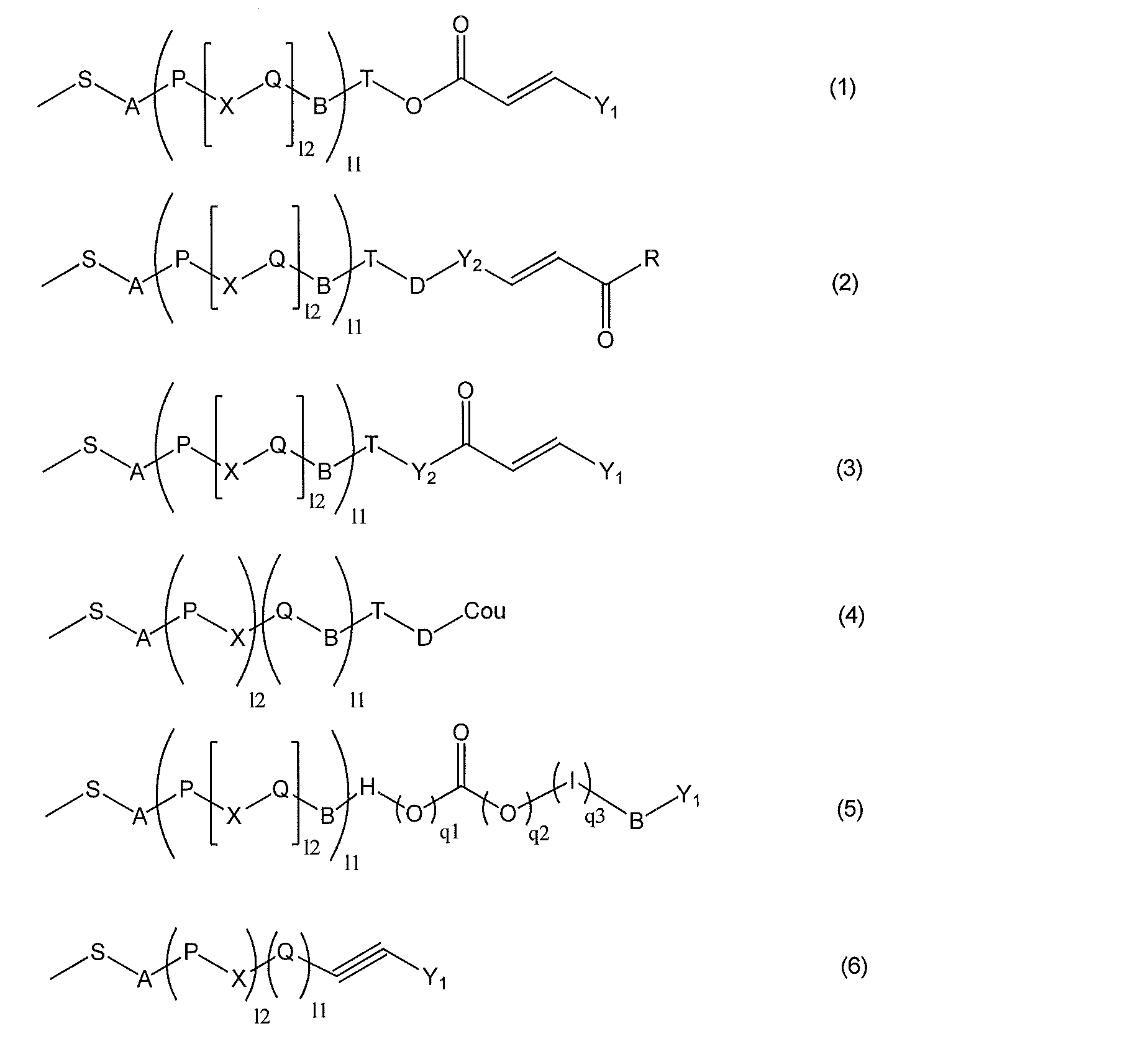
- the component (A) preferably has any one photosensitive side chain selected from the group consisting of the following formulas (1) to (6).
- A, B, and D are each independently a single bond, —O—, —CH 2 —, —COO—, —OCO—, —CONH—, —NH—CO—, —CH ⁇ CH—CO—.
- S is an alkylene group having 1 to 12 carbon atoms, and the hydrogen atom bonded thereto may be replaced by a halogen group;
- T is a single bond or an alkylene group having 1 to 12 carbon atoms, and a hydrogen atom bonded thereto may be replaced with a halogen group;
- Y 1 represents a ring selected from a monovalent benzene ring, naphthalene ring, biphenyl ring, furan ring, pyrrole ring and alicyclic hydrocarbon having 5 to 8 carbon atoms, or the same or selected from those substituents.
- R 0 is a hydrogen atom or a carbon number of 1 to 5 represents an alkyl group
- R 0 is a hydrogen atom or a carbon number of 1 to 5 represents an alkyl group
- Y 2 is a group selected from the group consisting of a divalent benzene ring, naphthalene ring, biphenyl ring, furan ring, pyrrole ring, alicyclic hydrocarbon having 5 to 8 carbon atoms, and combinations thereof
- the hydrogen atom bonded to each independently represents —NO 2 , —CN, —CH ⁇ C (CN) 2 , —CH ⁇ CH—CN, a
- R May be substituted with an alkyloxy group of R represents a hydroxy group, an alkoxy group having 1 to 6 carbon atoms, or the same definition as Y 1 ;
- X is a single bond, —COO—, —OCO—, —N ⁇ N—, —CH ⁇ CH—, —C ⁇ C—, —CH ⁇ CH—CO—O—, or —O—CO—CH ⁇ .
- X may be the same or different;
- Cou represents a coumarin-6-yl group or a coumarin-7-yl group, and the hydrogen atoms bonded thereto are independently —NO 2 , —CN, —CH ⁇ C (CN) 2 , —CH ⁇ CH— May be substituted with CN, a halogen group, an alkyl group having 1 to 5 carbon atoms, or an alkyloxy group having 1 to 5 carbon atoms; one of q1 and q2 is 1 and the other is 0; q3 is 0 or 1; P and Q are each independently selected from the group consisting of a divalent benzene ring, naphthalene ring, biphenyl ring, furan ring, pyrrole ring, alicyclic hydrocarbon having 5 to 8 carbon atoms, and combinations thereof.
- P or Q on the side to which —CH ⁇ CH— is bonded is an aromatic ring;
- the Ps may be the same or different, and when the number of Q is 2 or more, the Qs may be the same or different;
- l1 is 0 or 1;
- l2 is an integer from 0 to 2; when l1 and l2 are both 0,
- A represents a single bond when T is a single bond; when l1 is 1, B represents a single bond when T is a single bond;
- H and I are each independently a group selected from a divalent benzene ring, naphthalene ring, biphenyl ring, furan ring, pyrrole ring, and combinations thereof.
- the component (A) has any one photosensitive side chain selected from the group consisting of the following formulas (7) to (10): Good.
- the component (A) has any one photosensitive side chain selected from the group consisting of the following formulas (11) to (13): Good.
- A, X, l, m, m2 and R have the same definition as above.
- the component (A) preferably has a photosensitive side chain represented by the following formula (14) or (15).
- A, Y 1 , X, 1, m1, and m2 have the same definition as above.
- the component (A) preferably has a photosensitive side chain represented by the following formula (16) or (17).
- A, X, l and m have the same definition as above.
- the component (A) preferably has a photosensitive side chain represented by the following formula (18) or (19).
- A, B, Y 1 , q1, q2, m1, and m2 have the same definition as above.
- the component (A) preferably has a photosensitive side chain represented by the following formula (20).
- A, Y 1 , X, l and m have the same definition as above.
- the component (A) has any one liquid crystalline side chain selected from the group consisting of the following formulas (21) to (31): Good.
- A, B, q1 and q2 have the same definition as above;
- Y 3 is a group selected from the group consisting of a monovalent benzene ring, naphthalene ring, biphenyl ring, furan ring, nitrogen-containing heterocycle, alicyclic hydrocarbon having 5 to 8 carbon atoms, and combinations thereof.
- each hydrogen atom bonded thereto may be independently substituted with —NO 2 , —CN, a halogen group, an alkyl group having 1 to 5 carbon atoms, or an alkyloxy group having 1 to 5 carbon atoms;
- R 3 is a hydrogen atom, —NO 2 , —CN, —CH ⁇ C (CN) 2 , —CH ⁇ CH—CN, halogen group, monovalent benzene ring, naphthalene ring, biphenyl ring, furan ring, nitrogen-containing Represents a heterocyclic ring, an alicyclic hydrocarbon having 5 to 8 carbon atoms, an alkyl group having 1 to 12 carbon atoms, or an alkoxy group having 1 to 12 carbon atoms; l represents an integer of 1 to 12, m represents an integer of 0 to 2, provided that in the formulas (25) to (26), the sum of all m is 2 or more, and the formulas (27) to (28 ), The sum of all m
- ⁇ 14> a step of preparing the substrate (first substrate) of ⁇ 12>above;
- ⁇ 15> A lateral electric field drive type liquid crystal display device manufactured by the method of ⁇ 14> above.
- a substrate having a liquid crystal alignment film for a horizontal electric field drive type liquid crystal display element which is provided with high efficiency and orientation control ability and has excellent image sticking characteristics
- a horizontal electric field drive type liquid crystal display element having the substrate can do. Since the lateral electric field drive type liquid crystal display device manufactured by the method of the present invention is provided with the alignment control ability with high efficiency, the display characteristics are not impaired even when continuously driven for a long time. Moreover, the liquid crystal aligning agent of this invention can obtain the liquid crystal aligning film with the high linearity of the edge part of a liquid crystal aligning film, and a small rise
- the polymer composition used in the production method of the present invention has a photosensitive side chain polymer that can exhibit liquid crystallinity (hereinafter, also simply referred to as a side chain polymer), and the polymer composition
- the coating film obtained by using the product is a film having a photosensitive side chain polymer that can exhibit liquid crystallinity.
- This coating film is subjected to orientation treatment by irradiation with polarized light without being rubbed. And after polarized light irradiation, it will become the coating film (henceforth a liquid crystal aligning film) to which the orientation control ability was provided through the process of heating the side chain type polymer film.
- the slight anisotropy developed by the irradiation of polarized light becomes a driving force, and the liquid crystalline side chain polymer itself is efficiently reoriented by self-organization.
- a highly efficient alignment process can be realized as the liquid crystal alignment film, and a liquid crystal alignment film with high alignment control ability can be obtained.
- diisobutyl carbinol is used as the component (B) in addition to the side chain polymer as the component (A) and the organic solvent as the component (C).
- the method for producing a substrate having the liquid crystal alignment film of the present invention is [I] (A) a photosensitive side chain polymer that exhibits liquid crystallinity in a predetermined temperature range; (B) applying a polymer composition containing diisobutyl carbinol and (C) an organic solvent on a substrate having a conductive film for driving a transverse electric field to form a coating film; [II] a step of irradiating the coating film obtained in [I] with polarized ultraviolet rays; and [III] a step of heating the coating film obtained in [II]; Have Through the above steps, a liquid crystal alignment film for a lateral electric field drive type liquid crystal display element to which alignment control ability is imparted can be obtained, and a substrate having the liquid crystal alignment film can be obtained.
- a lateral electric field drive type liquid crystal display element can be obtained.
- the second substrate instead of using a substrate having no lateral electric field driving conductive film instead of a substrate having a lateral electric field driving conductive film, the above steps [I] to [III] (for lateral electric field driving) Since a substrate having no conductive film is used, for the sake of convenience, in this application, the steps [I ′] to [III ′] may be abbreviated as steps), thereby providing a first liquid crystal alignment film having alignment controllability. Two substrates can be obtained.
- the manufacturing method of the horizontal electric field drive type liquid crystal display element is: [IV] A step of obtaining a liquid crystal display element by arranging the first and second substrates obtained above so that the liquid crystal alignment films of the first and second substrates face each other with liquid crystal interposed therebetween; Have Thereby, a horizontal electric field drive type liquid crystal display element can be obtained.
- step [I] a polymer containing a photosensitive side-chain polymer that exhibits liquid crystallinity in a predetermined temperature range, diisobutylcarbinol, and an organic solvent on a substrate having a conductive film for driving a lateral electric field.
- the composition is applied to form a coating film.
- ⁇ Board> Although it does not specifically limit about a board
- the substrate has a conductive film for driving a lateral electric field.
- the conductive film include, but are not limited to, ITO (Indium Tin Oxide) and IZO (Indium Zinc Oxide) when the liquid crystal display element is a transmission type.
- examples of the conductive film include a material that reflects light such as aluminum, but are not limited thereto.
- a method for forming a conductive film on a substrate a conventionally known method can be used.
- a polymer composition is applied on a substrate having a conductive film for driving a lateral electric field, particularly on the conductive film.
- the polymer composition used in the production method of the present invention comprises: (A) a photosensitive side chain polymer that exhibits liquid crystallinity in a predetermined temperature range; (B) diisobutylcarbinol; and (C) organic A solvent.
- the component (A) is a photosensitive side chain polymer that exhibits liquid crystallinity within a predetermined temperature range.
- the (A) side chain polymer preferably reacts with light in the wavelength range of 250 nm to 400 nm and exhibits liquid crystallinity in the temperature range of 100 ° C. to 300 ° C.
- the (A) side chain polymer preferably has a photosensitive side chain that reacts with light in the wavelength range of 250 nm to 400 nm.
- the (A) side chain polymer preferably has a mesogenic group in order to exhibit liquid crystallinity in the temperature range of 100 ° C to 300 ° C.
- the side chain type polymer has a photosensitive side chain bonded to the main chain, and can cause a crosslinking reaction, an isomerization reaction, or a light fleece rearrangement in response to light.
- the structure of the side chain having photosensitivity is not particularly limited, but a structure that undergoes a crosslinking reaction or photofleece rearrangement in response to light is desirable, and a structure that causes a crosslinking reaction is more desirable. In this case, even if exposed to external stress such as heat, the achieved orientation control ability can be stably maintained for a long period of time.
- the structure of the photosensitive side chain polymer capable of exhibiting liquid crystallinity is not particularly limited as long as it satisfies such characteristics, but it is preferable to have a rigid mesogenic component in the side chain structure. In this case, stable liquid crystal alignment can be obtained when the side chain polymer is used as a liquid crystal alignment film.
- the polymer structure has, for example, a main chain and a side chain bonded to the main chain, and the side chain includes a mesogenic component such as a biphenyl group, a terphenyl group, a phenylcyclohexyl group, a phenylbenzoate group, and an azobenzene group, and a tip.
- a mesogenic component such as a biphenyl group, a terphenyl group, a phenylcyclohexyl group, a phenylbenzoate group, and an azobenzene group, and a tip.
- More specific examples of the structure of the photosensitive side chain polymer that can exhibit liquid crystallinity include hydrocarbon, (meth) acrylate, itaconate, fumarate, maleate, ⁇ -methylene- ⁇ -butyrolactone, styrene, vinyl , A main chain composed of at least one selected from the group consisting of radical polymerizable groups such as maleimide and norbornene and siloxane, and a side chain consisting of at least one of the following formulas (1) to (6) It is preferable that
- A, B, and D are each independently a single bond, —O—, —CH 2 —, —COO—, —OCO—, —CONH—, —NH—CO—, —CH ⁇ CH—CO—.
- S is an alkylene group having 1 to 12 carbon atoms, and the hydrogen atom bonded thereto may be replaced by a halogen group;
- T is a single bond or an alkylene group having 1 to 12 carbon atoms, and a hydrogen atom bonded thereto may be replaced with a halogen group;
- Y 1 represents a ring selected from a monovalent benzene ring, naphthalene ring, biphenyl ring, furan ring, pyrrole ring and alicyclic hydrocarbon having 5 to 8 carbon atoms, or the same or selected from those substituents.
- R 0 is a hydrogen atom or a carbon number of 1 to 5 represents an alkyl group
- R 0 is a hydrogen atom or a carbon number of 1 to 5 represents an alkyl group
- Y 2 is a group selected from the group consisting of a divalent benzene ring, naphthalene ring, biphenyl ring, furan ring, pyrrole ring, alicyclic hydrocarbon having 5 to 8 carbon atoms, and combinations thereof
- the hydrogen atom bonded to each independently represents —NO 2 , —CN, —CH ⁇ C (CN) 2 , —CH ⁇ CH—CN, a
- R May be substituted with an alkyloxy group of R represents a hydroxy group, an alkoxy group having 1 to 6 carbon atoms, or the same definition as Y 1 ;
- X is a single bond, —COO—, —OCO—, —N ⁇ N—, —CH ⁇ CH—, —C ⁇ C—, —CH ⁇ CH—CO—O—, or —O—CO—CH ⁇ .
- X may be the same or different;
- Cou represents a coumarin-6-yl group or a coumarin-7-yl group, and the hydrogen atoms bonded thereto are independently —NO 2 , —CN, —CH ⁇ C (CN) 2 , —CH ⁇ CH— May be substituted with CN, a halogen group, an alkyl group having 1 to 5 carbon atoms, or an alkyloxy group having 1 to 5 carbon atoms; one of q1 and q2 is 1 and the other is 0; q3 is 0 or 1; P and Q are each independently selected from the group consisting of a divalent benzene ring, naphthalene ring, biphenyl ring, furan ring, pyrrole ring, alicyclic hydrocarbon having 5 to 8 carbon atoms, and combinations thereof.
- P or Q on the side to which —CH ⁇ CH— is bonded is an aromatic ring;
- the Ps may be the same or different, and when the number of Q is 2 or more, the Qs may be the same or different;
- l1 is 0 or 1;
- l2 is an integer from 0 to 2; when l1 and l2 are both 0,
- A represents a single bond when T is a single bond; when l1 is 1, B represents a single bond when T is a single bond;
- H and I are each independently a group selected from a divalent benzene ring, naphthalene ring, biphenyl ring, furan ring, pyrrole ring, and combinations thereof.
- the side chain may be any one type of photosensitive side chain selected from the group consisting of the following formulas (7) to (10).
- the side chain may be any one type of photosensitive side chain selected from the group consisting of the following formulas (11) to (13).
- A, X, l, m, m2 and R have the same definition as above.
- the side chain may be a photosensitive side chain represented by the following formula (14) or (15).
- A, Y 1 , X, 1, m1, and m2 have the same definition as above.
- the side chain may be a photosensitive side chain represented by the following formula (16) or (17).
- A, X, l and m have the same definition as above.
- the side chain is preferably a photosensitive side chain represented by the following formula (18) or (19).
- A, B, Y1, q1, q2, m1, and m2 have the same definition as above.
- the side chain is preferably a photosensitive side chain represented by the following formula (20).
- A, Y 1 , X, l and m have the same definition as above.
- the (A) side chain polymer preferably has any one liquid crystalline side chain selected from the group consisting of the following formulas (21) to (31).
- A, B, q1 and q2 have the same definition as above;
- Y 3 is a group selected from the group consisting of a monovalent benzene ring, naphthalene ring, biphenyl ring, furan ring, nitrogen-containing heterocycle, alicyclic hydrocarbon having 5 to 8 carbon atoms, and combinations thereof.
- each hydrogen atom bonded thereto may be independently substituted with —NO 2 , —CN, a halogen group, an alkyl group having 1 to 5 carbon atoms, or an alkyloxy group having 1 to 5 carbon atoms;
- R 3 is a hydrogen atom, —NO 2 , —CN, —CH ⁇ C (CN) 2 , —CH ⁇ CH—CN, halogen group, monovalent benzene ring, naphthalene ring, biphenyl ring, furan ring, nitrogen-containing Represents a heterocyclic ring, an alicyclic hydrocarbon having 5 to 8 carbon atoms, an alkyl group having 1 to 12 carbon atoms, or an alkoxy group having 1 to 12 carbon atoms; l represents an integer of 1 to 12, m represents an integer of 0 to 2, provided that in the formulas (25) to (26), the sum of all m is 2 or more, and the formulas (27) to (28 ), The sum of all m
- the photosensitive side chain polymer capable of exhibiting the above liquid crystallinity can be obtained by polymerizing the photoreactive side chain monomer having the above photosensitive side chain and the liquid crystalline side chain monomer.
- the photoreactive side chain monomer is a monomer capable of forming a polymer having a photosensitive side chain at the side chain portion of the polymer when the polymer is formed.
- the photoreactive group possessed by the side chain the following structures and derivatives thereof are preferred.
- photoreactive side chain monomer examples include radical polymerizable groups such as hydrocarbon, (meth) acrylate, itaconate, fumarate, maleate, ⁇ -methylene- ⁇ -butyrolactone, styrene, vinyl, maleimide, norbornene, etc.
- a polymerizable side group composed of at least one selected from the group consisting of siloxane and a photosensitive side chain consisting of at least one of the above formulas (1) to (6), preferably, for example, the above formula (7 ) To (10), a photosensitive side chain comprising at least one of the above formulas (11) to (13), and a photosensitivity represented by the above formula (14) or (15).
- a photosensitive side chain a photosensitive side chain represented by the above formula (16) or (17), a photosensitive side chain represented by the above formula (18) or (19), and a photosensitivity represented by the above formula (20).
- Sex side chain It is preferable that it has a structure.
- the present application relates to novel compounds (1) to (11) represented by the following formulas (1) to (11), and the following formulas (12) to (17) as photoreactive and / or liquid crystalline side chain monomers. (12) to (17) are provided.
- R represents a hydrogen atom or a methyl group
- S represents an alkylene group having 2 to 10 carbon atoms
- R 10 represents Br or CN
- S represents an alkylene group having 2 to 10 carbon atoms
- u represents Represents 0 or 1
- Py represents a 2-pyridyl group, a 3-pyridyl group or a 4-pyridyl group.
- V represents 1 or 2.
- the liquid crystalline side chain monomer is a monomer in which a polymer derived from the monomer exhibits liquid crystallinity and the polymer can form a mesogenic group at a side chain site.
- a mesogenic group having a side chain even if it is a group having a mesogen structure alone such as biphenyl or phenylbenzoate, or a group having a mesogen structure by hydrogen bonding between side chains such as benzoic acid Good.
- the mesogenic group possessed by the side chain the following structure is preferable.
- liquid crystalline side chain monomers include hydrocarbon, (meth) acrylate, itaconate, fumarate, maleate, ⁇ -methylene- ⁇ -butyrolactone, styrene, vinyl, maleimide, norbornene and other radical polymerizable groups
- a structure having a polymerizable group composed of at least one selected from the group consisting of siloxanes and a side chain composed of at least one of the above formulas (21) to (31) is preferable.
- the side chain polymer can be obtained by the polymerization reaction of the above-described photoreactive side chain monomer that exhibits liquid crystallinity. Further, it can be obtained by copolymerization of a photoreactive side chain monomer that does not exhibit liquid crystallinity and a liquid crystalline side chain monomer, or by copolymerization of a photoreactive side chain monomer that exhibits liquid crystallinity and a liquid crystalline side chain monomer. it can. Furthermore, it can be copolymerized with other monomers as long as the liquid crystallinity is not impaired.
- Examples of other monomers include industrially available monomers capable of radical polymerization reaction. Specific examples of the other monomer include unsaturated carboxylic acid, acrylic ester compound, methacrylic ester compound, maleimide compound, acrylonitrile, maleic anhydride, styrene compound and vinyl compound.
- the unsaturated carboxylic acid include acrylic acid, methacrylic acid, itaconic acid, maleic acid, fumaric acid and the like.
- the acrylic ester compound include methyl acrylate, ethyl acrylate, isopropyl acrylate, benzyl acrylate, naphthyl acrylate, anthryl acrylate, anthryl methyl acrylate, phenyl acrylate, 2,2,2-trifluoroethyl acrylate, tert-butyl.
- methacrylic acid ester compound examples include methyl methacrylate, ethyl methacrylate, isopropyl methacrylate, benzyl methacrylate, naphthyl methacrylate, anthryl methacrylate, anthryl methyl methacrylate, phenyl methacrylate, 2,2,2-trifluoroethyl methacrylate, tert-butyl.
- (Meth) acrylate compounds having a cyclic ether group such as glycidyl (meth) acrylate, (3-methyl-3-oxetanyl) methyl (meth) acrylate, and (3-ethyl-3-oxetanyl) methyl (meth) acrylate are also used. be able to.
- Examples of the vinyl compound include vinyl ether, methyl vinyl ether, benzyl vinyl ether, 2-hydroxyethyl vinyl ether, phenyl vinyl ether, and propyl vinyl ether.
- Examples of the styrene compound include styrene, methylstyrene, chlorostyrene, bromostyrene, and the like.
- Examples of maleimide compounds include maleimide, N-methylmaleimide, N-phenylmaleimide, and N-cyclohexylmaleimide.
- the production method of the side chain polymer of the present embodiment is not particularly limited, and a general-purpose method that is handled industrially can be used. Specifically, it can be produced by cationic polymerization, radical polymerization, or anionic polymerization using a vinyl group of a liquid crystalline side chain monomer or photoreactive side chain monomer. Among these, radical polymerization is particularly preferable from the viewpoint of ease of reaction control.
- RAFT reversible addition-cleavage chain transfer
- a radical thermal polymerization initiator is a compound that generates radicals when heated to a decomposition temperature or higher.
- radical thermal polymerization initiators include ketone peroxides (methyl ethyl ketone peroxide, cyclohexanone peroxide, etc.), diacyl peroxides (acetyl peroxide, benzoyl peroxide, etc.), hydroperoxides (peroxidation).
- the radical photopolymerization initiator is not particularly limited as long as it is a compound that initiates radical polymerization by light irradiation.
- examples of such radical photopolymerization initiators include benzophenone, Michler's ketone, 4,4′-bis (diethylamino) benzophenone, xanthone, thioxanthone, isopropylxanthone, 2,4-diethylthioxanthone, 2-ethylanthraquinone, acetophenone, 2-hydroxy -2-methylpropiophenone, 2-hydroxy-2-methyl-4'-isopropylpropiophenone, 1-hydroxycyclohexyl phenyl ketone, isopropyl benzoin ether, isobutyl benzoin ether, 2,2-diethoxyacetophenone, 2,2 -Dimethoxy-2-phenylacetophenone, camphorquinone, benzanthrone, 2-methyl-1- [4- (
- the radical polymerization method is not particularly limited, and an emulsion polymerization method, suspension polymerization method, dispersion polymerization method, precipitation polymerization method, bulk polymerization method, solution polymerization method and the like can be used.
- the organic solvent used for the polymerization reaction of the photosensitive side chain polymer capable of exhibiting liquid crystallinity is not particularly limited as long as the generated polymer is soluble. Specific examples are given below.
- organic solvents may be used alone or in combination. Furthermore, even if it is a solvent which does not dissolve the polymer
- the polymerization temperature at the time of radical polymerization can be selected from any temperature of 30 ° C. to 150 ° C., but is preferably in the range of 50 ° C. to 100 ° C.
- the reaction can be carried out at any concentration, but if the concentration is too low, it is difficult to obtain a high molecular weight polymer, and if the concentration is too high, the viscosity of the reaction solution becomes too high and uniform stirring is difficult. Therefore, the monomer concentration is preferably 1% by mass to 50% by mass, more preferably 5% by mass to 30% by mass.
- the initial stage of the reaction is carried out at a high concentration, and then an organic solvent can be added.
- the molecular weight of the obtained polymer is decreased when the ratio of the radical polymerization initiator is large relative to the monomer, and the molecular weight of the obtained polymer is increased when the ratio is small, the ratio of the radical initiator is
- the content is preferably 0.1 mol% to 10 mol% with respect to the monomer to be polymerized. Further, various monomer components, solvents, initiators and the like can be added during the polymerization.
- the polymer deposited in a poor solvent and precipitated can be recovered by filtration and then dried at normal temperature or under reduced pressure at room temperature or by heating.
- impurities in the polymer can be reduced.
- the poor solvent at this time include alcohols, ketones, hydrocarbons and the like, and it is preferable to use three or more kinds of poor solvents selected from these because purification efficiency is further improved.
- the molecular weight of the (A) side chain polymer of the present invention is measured by a GPC (Gel Permeation Chromatography) method in consideration of the strength of the obtained coating film, workability at the time of forming the coating film, and uniformity of the coating film.
- the weight average molecular weight is preferably 2,000 to 1,000,000, more preferably 5,000 to 200,000.
- the polymer composition used in the present invention is preferably prepared as a coating solution so as to be suitable for forming a liquid crystal alignment film. That is, the polymer composition used in the present invention is preferably prepared as a solution in which a resin component for forming a resin film is dissolved in an organic solvent.
- the resin component is a resin component containing a photosensitive side chain polymer capable of exhibiting the liquid crystallinity already described.
- the content of the resin component is preferably 1% by mass to 20% by mass, more preferably 3% by mass to 15% by mass, and particularly preferably 3% by mass to 10% by mass.
- the resin component described above may be a photosensitive side chain polymer that can all exhibit the above-described liquid crystallinity, but does not impair the liquid crystal developing ability and the photosensitive performance.
- Other polymers may be mixed within the range.
- the content of the other polymer in the resin component is 0.5 to 80% by mass, preferably 1 to 50% by mass.
- examples of such other polymers include polymers that are made of poly (meth) acrylate, polyamic acid, polyimide, and the like and are not a photosensitive side chain polymer that can exhibit liquid crystallinity.
- the polymer composition used in the present invention contains diisobutyl carbinol represented by the following structural formula, that is, 2,6-dimethyl-4-heptanol as the component (B).
- the liquid crystal aligning agent contains diisobutyl carbinol
- the wetting and spreading properties are suppressed as compared to the liquid crystal aligning agent not containing the liquid crystal aligning agent, so that the linearity of the end portion when the liquid crystal aligning film is formed becomes high. .
- the rising of an edge part can be suppressed.
- diisobutyl carbinol is a good solvent, such as N-methyl-2-pyrrolidone (NMP) or N-ethyl-2, compared to poor solvents such as butyl cellosolve or propylene glycol monobutyl ether because of the boiling point / vapor pressure relationship.
- the content is preferably 20 to 60 parts by mass, more preferably 25 to 45 parts by mass with respect to 100 parts by mass of the organic solvent of component (C).
- Organic solvent used for the polymer composition used in the present invention is not particularly limited as long as it is an organic solvent that dissolves the resin component. Specific examples are given below. N, N-dimethylformamide, N, N-dimethylacetamide, N-methyl-2-pyrrolidone, N-methylcaprolactam, 2-pyrrolidone, N-ethylpyrrolidone, N-vinylpyrrolidone, dimethylsulfoxide, tetramethylurea, pyridine, Dimethylsulfone, hexamethylsulfoxide, ⁇ -butyrolactone, 3-methoxy-N, N-dimethylpropanamide, 3-ethoxy-N, N-dimethylpropanamide, 3-butoxy-N, N-dimethylpropanamide, 1,3 -Dimethyl-imidazolidinone, ethyl amyl ketone, methyl nonyl ketone, methyl ethyl ketone
- the polymer composition used in the present invention may contain components other than the above components (A), (B) and (C). Examples thereof include solvents and compounds that improve the film thickness uniformity and surface smoothness when the polymer composition is applied, and compounds that improve the adhesion between the liquid crystal alignment film and the substrate.
- the present invention is not limited to this.
- solvent poor solvent which improves the uniformity of film thickness and surface smoothness.
- solvents may be used alone or in combination.
- it is preferably 5% by mass to 80% by mass of the total solvent, more preferably so as not to significantly reduce the solubility of the entire solvent contained in the polymer composition. Is 20% by mass to 60% by mass.
- Examples of the compound that improves film thickness uniformity and surface smoothness include fluorine-based surfactants, silicone-based surfactants, and nonionic surfactants. More specifically, for example, Ftop (registered trademark) 301, EF303, EF352 (manufactured by Tochem Products), MegaFac (registered trademark) F171, F173, R-30 (manufactured by DIC), Florard FC430, FC431 (Manufactured by Sumitomo 3M), Asahi Guard (registered trademark) AG710 (manufactured by Asahi Glass Company), Surflon (registered trademark) S-382, SC101, SC102, SC103, SC104, SC105, SC106 (manufactured by AGC Seimi Chemical Co., Ltd.) It is done.
- the use ratio of these surfactants is preferably 0.01 to 2 parts by mass, more preferably 0.01 to 1 part by mass with respect to 100 parts by mass of the resin component contained in the polymer
- the compound that improves the adhesion between the liquid crystal alignment film and the substrate include the following functional silane-containing compounds.
- phenoplasts and epoxy group-containing compounds for the purpose of preventing the deterioration of electrical characteristics due to the backlight when the liquid crystal display element is constructed
- An agent may be contained in the polymer composition. Specific phenoplast additives are shown below, but are not limited to this structure.
- Specific epoxy group-containing compounds include ethylene glycol diglycidyl ether, polyethylene glycol diglycidyl ether, propylene glycol diglycidyl ether, tripropylene glycol diglycidyl ether, polypropylene glycol diglycidyl ether, neopentyl glycol diglycidyl ether, 1, 6-hexanediol diglycidyl ether, glycerin diglycidyl ether, 2,2-dibromoneopentyl glycol diglycidyl ether, 1,3,5,6-tetraglycidyl-2,4-hexanediol, N, N, N ′, N ′,-tetraglycidyl-m-xylenediamine, 1,3-bis (N, N-diglycidylaminomethyl) cyclohexane, N, N, N ′, N ′,-tetraglycidyl- , 4'-diaminodip
- the amount used is preferably 0.1 to 30 parts by mass with respect to 100 parts by mass of the resin component contained in the polymer composition. More preferably, it is 1 to 20 parts by mass. If the amount used is less than 0.1 parts by mass, the effect of improving the adhesion cannot be expected, and if it exceeds 30 parts by mass, the orientation of the liquid crystal may deteriorate.
- a photosensitizer can also be used as an additive. Colorless and triplet sensitizers are preferred.
- photosensitizers aromatic nitro compounds, coumarins (7-diethylamino-4-methylcoumarin, 7-hydroxy4-methylcoumarin), ketocoumarins, carbonyl biscoumarins, aromatic 2-hydroxyketones, and amino-substituted Aromatic 2-hydroxyketones (2-hydroxybenzophenone, mono- or di-p- (dimethylamino) -2-hydroxybenzophenone), acetophenone, anthraquinone, xanthone, thioxanthone, benzanthrone, thiazoline (2-benzoylmethylene-3 -Methyl- ⁇ -naphthothiazoline, 2- ( ⁇ -naphthoylmethylene) -3-methylbenzothiazoline, 2- ( ⁇ -naphthoylmethylene) -3-methylbenzothiazoline, 2- (4-b
- Aromatic 2-hydroxy ketone (benzophenone), coumarin, ketocoumarin, carbonyl biscoumarin, acetophenone, anthraquinone, xanthone, thioxanthone, and acetophenone ketal are preferred.
- a dielectric, a conductive substance, or the like for the purpose of changing the electrical properties such as the dielectric constant and conductivity of the liquid crystal alignment film, as long as the effects of the present invention are not impaired.
- a crosslinkable compound may be added for the purpose of increasing the hardness and density of the liquid crystal alignment film.
- the method for applying the polymer composition described above onto a substrate having a conductive film for driving a lateral electric field is not particularly limited.
- the application method is generally performed by screen printing, offset printing, flexographic printing, an inkjet method, or the like.
- Other coating methods include a dipping method, a roll coater method, a slit coater method, a spinner method (rotary coating method), or a spray method, and these may be used depending on the purpose.
- the polymer composition After the polymer composition is applied on a substrate having a conductive film for driving a horizontal electric field, it is 50 to 200 ° C., preferably 50 to 200 ° C. by a heating means such as a hot plate, a heat circulation oven or an IR (infrared) oven.
- the solvent can be evaporated at 150 ° C. to obtain a coating film.
- the drying temperature at this time is preferably lower than the liquid crystal phase expression temperature of the side chain polymer. If the thickness of the coating film is too thick, it will be disadvantageous in terms of power consumption of the liquid crystal display element, and if it is too thin, the reliability of the liquid crystal display element may be lowered.
- it is preferably 5 nm to 300 nm, more preferably 10 nm to 150 nm. It is. In addition, it is also possible to provide the process of cooling the board
- step [II] the coating film obtained in step [I] is irradiated with polarized ultraviolet rays.
- the substrate is irradiated with polarized ultraviolet rays through a polarizing plate from a certain direction.
- ultraviolet rays to be used ultraviolet rays having a wavelength in the range of 100 nm to 400 nm can be used.
- the optimum wavelength is selected through a filter or the like depending on the type of coating film to be used.
- ultraviolet light having a wavelength in the range of 290 nm to 400 nm can be selected and used so that the photocrosslinking reaction can be selectively induced.
- the ultraviolet light for example, light emitted from a high-pressure mercury lamp can be used.
- the irradiation amount of polarized ultraviolet rays depends on the coating film used.
- the amount of irradiation is polarized ultraviolet light that realizes the maximum value of ⁇ A (hereinafter also referred to as ⁇ Amax), which is the difference between the ultraviolet light absorbance in a direction parallel to the polarization direction of polarized ultraviolet light and the ultraviolet light absorbance in a direction perpendicular to the polarization direction of the polarized ultraviolet light.
- the amount is preferably in the range of 1% to 70%, more preferably in the range of 1% to 50%.
- step [III] the ultraviolet-irradiated coating film polarized in step [II] is heated.
- An orientation control ability can be imparted to the coating film by heating.
- a heating means such as a hot plate, a heat circulation type oven, or an IR (infrared) type oven can be used.
- the heating temperature can be determined in consideration of the temperature at which the liquid crystallinity of the coating film used is developed.
- the heating temperature is preferably within the temperature range of the temperature at which the side chain polymer exhibits liquid crystallinity (hereinafter referred to as liquid crystal expression temperature).
- the liquid crystal expression temperature on the coating film surface is expected to be lower than the liquid crystal expression temperature when a photosensitive side chain polymer that can exhibit liquid crystallinity is observed in bulk.
- the heating temperature is more preferably within the temperature range of the liquid crystal expression temperature on the coating film surface. That is, the temperature range of the heating temperature after irradiation with polarized ultraviolet rays is 10 ° C. lower than the lower limit of the temperature range of the liquid crystal expression temperature of the side chain polymer used, and 10 ° C.
- the liquid crystal expression temperature is not less than the glass transition temperature (Tg) at which the side chain polymer or coating film surface undergoes a phase transition from the solid phase to the liquid crystal phase, and from the liquid crystal phase to the isotropic phase (isotropic phase). It means a temperature below the isotropic phase transition temperature (Tiso) that causes a phase transition.
- the production method of the present invention can realize highly efficient introduction of anisotropy into the coating film. And a board
- the step [IV] is performed in the same manner as in the above [I ′] to [III ′], similarly to the substrate (first substrate) obtained in [III] and having the liquid crystal alignment film on the conductive film for lateral electric field driving.
- the obtained liquid crystal alignment film-attached substrate (second substrate) having no conductive film is placed oppositely so that both liquid crystal alignment films face each other through liquid crystal, and a liquid crystal cell is formed by a known method.
- This is a step of manufacturing a lateral electric field drive type liquid crystal display element.
- a substrate having no lateral electric field driving conductive film was used in place of the substrate having the lateral electric field driving conductive film in the step [I].
- steps [I] to [III] It can be carried out in the same manner as in steps [I] to [III]. Since the difference between the steps [I] to [III] and the steps [I ′] to [III ′] is only the presence or absence of the conductive film, the description of the steps [I ′] to [III ′] is omitted. To do.
- the first and second substrates described above are prepared, spacers are dispersed on the liquid crystal alignment film of one substrate, and the liquid crystal alignment film surface is on the inside.
- the other substrate is bonded and the liquid crystal is injected under reduced pressure, or the liquid crystal is dropped on the liquid crystal alignment film surface on which the spacers are dispersed, and then the substrate is bonded and sealed.
- Etc. can be illustrated.
- the diameter of the spacer at this time is preferably 1 ⁇ m to 30 ⁇ m, more preferably 2 ⁇ m to 10 ⁇ m. This spacer diameter determines the distance between the pair of substrates that sandwich the liquid crystal layer, that is, the thickness of the liquid crystal layer.
- substrate with a coating film of this invention irradiates the polarized ultraviolet-ray, after apply
- the coating film used in the present invention realizes the introduction of highly efficient anisotropy into the coating film by utilizing the principle of molecular reorientation induced by the side chain photoreaction and liquid crystallinity. .
- an embodiment using a side chain type polymer having a structure having a photocrosslinkable group as a photoreactive group is the first embodiment, a structure having a photofleece rearrangement group or a group causing isomerization as a photoreactive group
- An embodiment using the side chain type polymer will be referred to as a second embodiment.
- FIG. 1 schematically shows an anisotropic introduction process in a method for producing a liquid crystal alignment film using a side chain polymer having a structure having a photocrosslinkable group as a photoreactive group in the first embodiment of the present invention. It is a figure of one example demonstrated to.
- FIG. 1 (a) is a diagram schematically showing the state of the side chain polymer film before irradiation with polarized light
- FIG. 1 (b) is a schematic diagram showing the state of the side chain polymer film after irradiation with polarized light
- FIG. 1 (c) is a diagram schematically showing the state of the side-chain polymer film after heating, and particularly when the introduced anisotropy is small, that is, the first aspect of the present invention.
- 1 is a schematic diagram when the ultraviolet ray irradiation amount in the step [II] is within a range of 1% to 15% of the ultraviolet ray irradiation amount that maximizes ⁇ A.
- FIG. 2 is a schematic illustration of anisotropy introduction treatment in a method for producing a liquid crystal alignment film using a side chain polymer having a structure having a photocrosslinkable group as a photoreactive group in the first embodiment of the present invention. It is a figure of one example demonstrated to.
- FIG. 2A is a diagram schematically showing the state of the side chain polymer film before irradiation with polarized light
- FIG. 2B is a schematic diagram showing the state of the side chain polymer film after irradiation with polarized light.
- FIG. 2 (c) is a diagram schematically showing the state of the side-chain polymer film after heating, and particularly when the introduced anisotropy is large, that is, the first aspect of the present invention.
- 1 is a schematic diagram when the ultraviolet ray irradiation amount in the step [II] is within a range of 15% to 70% of the ultraviolet ray irradiation amount that maximizes ⁇ A.
- FIG. 3 shows a side chain polymer having a structure having a photo-isomerizable group as a photoreactive group or a photo-Fleece rearrangement group represented by the above formula (18) in the second embodiment of the present invention. It is a figure of one example which illustrates typically the introduction process of anisotropy in the manufacturing method of the used liquid crystal aligning film.
- FIG. 3A is a diagram schematically showing the state of the side chain polymer film before polarized light irradiation
- FIG. 3B is a schematic diagram of the state of the side chain polymer film after polarized light irradiation.
- 3 (c) is a diagram schematically showing the state of the side-chain polymer film after heating, and particularly when the introduced anisotropy is small, that is, the first aspect of the present invention.
- 2 is a schematic diagram when the ultraviolet irradiation amount in the step [II] is within a range of 1% to 70% of the ultraviolet irradiation amount that maximizes ⁇ A.
- FIG. 4 shows the production of a liquid crystal alignment film using a side chain polymer having a structure having a photo-Fleece rearrangement group represented by the above formula (19) as a photoreactive group in the second embodiment of the present invention. It is a figure of one example which illustrates typically the introduction processing of anisotropy in a method.
- FIG. 4A is a diagram schematically showing the state of the side chain polymer film before irradiation with polarized light
- FIG. 4B is a schematic diagram of the state of the side chain polymer film after irradiation with polarized light.
- FIG. 4 (c) is a diagram schematically showing the state of the side-chain polymer film after heating.
- 2 is a schematic diagram when the ultraviolet irradiation amount in the step [II] is within a range of 1% to 70% of the ultraviolet irradiation amount that maximizes ⁇ A.
- the ultraviolet irradiation amount in the step [II] is in the range of 1% to 15% of the ultraviolet irradiation amount that maximizes ⁇ A.
- the coating film 1 is formed on the substrate.
- Fig.1 (a) in the coating film 1 formed on the board
- the ultraviolet irradiation amount in the step [II] is in the range of 15% to 70% of the ultraviolet irradiation amount that maximizes ⁇ A.
- the coating film 3 is formed on the substrate. As shown in FIG. 2A, the coating film 3 formed on the substrate has a structure in which the side chains 4 are randomly arranged. According to the random arrangement of the side chains 4 of the coating film 3, the mesogenic components and the photosensitive groups of the side chains 4 are also randomly oriented, and the coating film 2 is isotropic.
- a side chain type having a structure having a photo-isomerizable group or a photo-Fleece rearrangement group represented by the above formula (18) in the treatment for introducing anisotropy into the coating film In the case of using a liquid crystal alignment film using a polymer, when the ultraviolet irradiation amount in the step [II] is in the range of 1% to 70% of the ultraviolet irradiation amount that maximizes ⁇ A, first, The coating film 5 is formed. As shown in FIG. 3A, the coating film 5 formed on the substrate has a structure in which the side chains 6 are randomly arranged. According to the random arrangement of the side chain 6 of the coating film 5, the mesogenic component and the photosensitive group of the side chain 6 are also randomly oriented, and the side chain type polymer film 5 is isotropic.
- liquid crystal alignment using a side chain type polymer having a structure having a light Fleece rearrangement group represented by the above formula (19) in the treatment for introducing anisotropy into the coating film In the case of using a film, when the ultraviolet irradiation amount in the step [II] is within the range of 1% to 70% of the ultraviolet irradiation amount that maximizes ⁇ A, first, the coating film 7 is formed on the substrate. . As shown in FIG. 4A, the coating film 7 formed on the substrate has a structure in which the side chains 8 are arranged at random. According to the random arrangement of the side chains 8 of the coating film 7, the mesogenic components and the photosensitive groups of the side chains 8 are also randomly oriented, and the coating film 7 is isotropic.
- the ultraviolet irradiation amount in the step [II] is within the range of 1% to 15% of the ultraviolet irradiation amount that maximizes ⁇ A
- polarized ultraviolet rays are irradiated.
- the photosensitive group of the side chain 2a having the photosensitive group among the side chains 2 arranged in a direction parallel to the polarization direction of the ultraviolet rays is preferentially subjected to dimerization reaction or the like.
- Dimerization reaction or the like causes a photoreaction.
- the density of the side chain 2a that has undergone photoreaction becomes slightly higher in the polarization direction of the irradiated ultraviolet light, and as a result, very small anisotropy is imparted to the coating film 1.
- the ultraviolet irradiation amount in the step [II] is within the range of 15% to 70% of the ultraviolet irradiation amount that maximizes ⁇ A
- polarized ultraviolet rays are irradiated.
- the photosensitive group of the side chain 4a having the photosensitive group among the side chains 4 arranged in a direction parallel to the polarization direction of the ultraviolet rays is preferentially subjected to dimerization reaction or the like.
- the density of the side chain 4a that has undergone photoreaction increases in the polarization direction of the irradiated ultraviolet light, and as a result, a small anisotropy is imparted to the coating film 3.
- the density of the side chain 6a subjected to photoreaction becomes slightly higher in the polarization direction of the irradiated ultraviolet rays, and as a result, very small anisotropy is imparted to the coating film 5.
- the amount of ultraviolet irradiation in the step [II] is obtained using a coating film using a side chain polymer having a structure having a photo-Fleece rearrangement group represented by the above formula (19). Is within the range of 1% to 70% of the amount of UV irradiation that maximizes ⁇ A, the isotropic coating film 7 is irradiated with polarized UV light. Then, as shown in FIG. 4 (b), the photosensitive group of the side chain 8a having the photosensitive group among the side chains 8 arranged in a direction parallel to the polarization direction of the ultraviolet rays is preferentially subjected to light fleece rearrangement or the like. Causes a photoreaction. As a result, the density of the side chain 8a that has undergone photoreaction increases in the polarization direction of the irradiated ultraviolet light, and as a result, small anisotropy is imparted to the coating film 7.
- the coating film 1 after the polarized light irradiation 1 Is heated to a liquid crystal state. Then, as shown in FIG.1 (c), in the coating film 1, the amount of the generated crosslinking reaction differs between the direction parallel to the polarization direction of the irradiated ultraviolet rays and the direction perpendicular thereto. In this case, since the amount of the crosslinking reaction generated in the direction parallel to the polarization direction of the irradiated ultraviolet ray is very small, this crosslinking reaction site functions as a plasticizer.
- the liquid crystallinity in the direction perpendicular to the polarization direction of the irradiated ultraviolet light is higher than the liquid crystallinity in the parallel direction, and the side chain 2 containing the mesogenic component is reoriented by self-organizing in the direction parallel to the polarization direction of the irradiated ultraviolet light.
- the very small anisotropy of the coating film 1 induced by the photocrosslinking reaction is amplified by heat, and a larger anisotropy is imparted to the coating film 1.
- the coating film after polarized light irradiation 3 is heated to a liquid crystal state.
- the amount of the generated crosslinking reaction differs between the direction parallel to the polarization direction of the irradiated ultraviolet rays and the direction perpendicular thereto. Therefore, the side chain 4 containing the mesogenic component is reoriented by self-organizing in a direction parallel to the polarization direction of the irradiated ultraviolet light.
- the small anisotropy of the coating film 3 induced by the photocrosslinking reaction is amplified by heat, and a larger anisotropy is imparted to the coating film 3.
- a coating film using a side-chain polymer having a structure having a photo-isomerizable group or a photo-Fleece rearrangement group represented by the above formula (18) is used.
- the ultraviolet irradiation amount in the step [II] is within the range of 1% to 70% of the ultraviolet irradiation amount that maximizes ⁇ A
- the coating film 5 after polarized irradiation is heated to be in a liquid crystal state.
- generated light fleece rearrangement reaction differs between the direction parallel to the polarization direction of irradiation ultraviolet rays, and a perpendicular
- the liquid crystal alignment force of the light fleece rearrangement generated in the direction perpendicular to the polarization direction of the irradiated ultraviolet light is stronger than the liquid crystal alignment force of the side chain before the reaction, it is self-organized in the direction perpendicular to the polarization direction of the irradiated ultraviolet light.
- the side chain 6 containing the mesogenic component is reoriented.
- the very small anisotropy of the coating film 5 induced by the photofleece rearrangement reaction is amplified by heat, and a larger anisotropy is imparted to the coating film 5.
- a coating film using a side chain type polymer having a structure having a photofleece rearrangement group represented by the above formula (19) is used.
- the ultraviolet irradiation amount is in the range of 1% to 70% of the ultraviolet irradiation amount that maximizes ⁇ A
- the coated film 7 after polarized irradiation is heated to a liquid crystal state.
- the amount of the generated light fleece rearrangement reaction differs between the direction parallel to the polarization direction of the irradiated ultraviolet light and the direction perpendicular thereto. .
- the anchoring force of the optical fleece rearrangement 8 (a) is stronger than that of the side chain 8 before the rearrangement, when a certain amount or more of the optical fleece rearrangement occurs, it is self-assembled in a direction parallel to the polarization direction of the irradiated ultraviolet light.
- the side chain 8 containing the mesogenic component is reoriented.
- the small anisotropy of the coating film 7 induced by the photofleece rearrangement reaction is amplified by heat, and a larger anisotropy is imparted to the coating film 7.
- the coating film used in the method of the present invention is a liquid crystal alignment film having anisotropy introduced with high efficiency and excellent alignment control ability by sequentially performing irradiation of polarized ultraviolet rays on the coating film and heat treatment. can do.
- the irradiation amount of polarized ultraviolet rays to the coating film and the heating temperature in the heat treatment are optimized. Thereby, introduction of anisotropy into the coating film with high efficiency can be realized.
- the optimum irradiation amount of polarized ultraviolet rays for introducing highly efficient anisotropy into the coating film used in the present invention is such that the photosensitive group undergoes photocrosslinking reaction, photoisomerization reaction, or photofries rearrangement reaction in the coating film.
- the photo-crosslinking reaction, photoisomerization reaction, or photo-fleece rearrangement reaction has few photosensitive groups in the side chain, the amount of photoreaction will not be sufficient. . In that case, sufficient self-organization does not proceed even after heating.
- the crosslinking reaction between the side chains is caused when the photosensitive group of the side chain undergoing the crosslinking reaction becomes excessive. Too much progress. In that case, the resulting film may become rigid and hinder the progress of self-assembly by subsequent heating.
- the coating film used in the present invention is irradiated with polarized ultraviolet rays to the structure having the light Fleece rearrangement group, if the photosensitive group of the side chain that undergoes the light Fleece rearrangement reaction becomes excessive, the liquid crystallinity of the coating film Will drop too much.
- the liquid crystallinity of the obtained film is also lowered, which may hinder the progress of self-assembly by subsequent heating. Furthermore, when irradiating polarized ultraviolet light to a structure having a photo-fleece rearrangement group, if the amount of ultraviolet light irradiation is too large, the side-chain polymer is photodegraded, preventing the subsequent self-organization by heating. It may become.
- the optimum amount of the photopolymerization reaction, photoisomerization reaction, or photofleece rearrangement reaction of the side chain photosensitive group by irradiation with polarized ultraviolet rays is the side chain polymer film. It is preferably 0.1 to 40 mol%, more preferably 0.1 to 20 mol% of the photosensitive group possessed by.
- the coating film used in the method of the present invention by optimizing the irradiation amount of polarized ultraviolet rays, photocrosslinking reaction or photoisomerization reaction of photosensitive groups or photofleece rearrangement reaction in the side chain of the side chain polymer film Optimize the amount of. Then, in combination with the subsequent heat treatment, highly efficient introduction of anisotropy into the coating film used in the present invention is realized. In that case, a suitable amount of polarized ultraviolet rays can be determined based on the evaluation of ultraviolet absorption of the coating film used in the present invention.
- the ultraviolet absorption in the direction parallel to the polarization direction of the polarized ultraviolet ray and the ultraviolet absorption in the vertical direction after the irradiation with the polarized ultraviolet ray are measured.
- ⁇ A which is the difference between the ultraviolet absorbance in the direction parallel to the polarization direction of polarized ultraviolet rays and the ultraviolet absorbance in the direction perpendicular to the polarization direction of the polarized ultraviolet rays.
- the maximum value of ⁇ A ( ⁇ Amax) realized in the coating film used in the present invention and the irradiation amount of polarized ultraviolet light that realizes it are obtained.
- a preferable amount of polarized ultraviolet rays to be irradiated in the production of the liquid crystal alignment film can be determined on the basis of the amount of polarized ultraviolet rays to realize this ⁇ Amax.
- the amount of irradiation of polarized ultraviolet rays onto the coating film used in the present invention is preferably in the range of 1% to 70% of the amount of polarized ultraviolet rays that realizes ⁇ Amax. More preferably, it is within the range of 50%.
- the irradiation amount of polarized ultraviolet light within the range of 1% to 50% of the amount of polarized ultraviolet light that realizes ⁇ Amax is 0. 0% of the entire photosensitive group of the side chain polymer film. 1 mol% to 20 mol% corresponds to the amount of polarized ultraviolet light that undergoes a photocrosslinking reaction.
- a suitable heating temperature as described above is set based on the liquid crystal temperature range of the side chain polymer. It is good to decide. Therefore, for example, when the liquid crystal temperature range of the side chain polymer used in the present invention is 100 ° C. to 200 ° C., the heating temperature after irradiation with polarized ultraviolet light is desirably 90 ° C. to 190 ° C. By doing so, greater anisotropy is imparted to the coating film used in the present invention.
- the liquid crystal display element provided by the present invention exhibits high reliability against external stresses such as light and heat.
- the lateral electric field drive type liquid crystal display element substrate manufactured by the method of the present invention or the lateral electric field drive type liquid crystal display element having the substrate has excellent reliability, large screen and high definition. It can be suitably used for LCD TVs.
- MA1 was synthesized by a synthesis method described in a patent document (WO2011 / 084546).
- NEP 49.0 g was added to the resulting methacrylate polymer powder (A) (6.0 g), and dissolved by stirring at room temperature for 5 hours.
- PB 2,0.0 g
- DIBC 2,5-bis(trimethoxycarbonate)
- NEP 49.0 g was added to the resulting methacrylate polymer powder (A) (6.0 g), and dissolved by stirring at room temperature for 5 hours.
- PB 10.0 g
- DIBC 35.0 g were added to this solution and stirred to obtain a liquid crystal aligning agent (A2).
- NEP 49.0 g was added to the resulting methacrylate polymer powder (A) (6.0 g), and dissolved by stirring at room temperature for 5 hours.
- the ink-jet coating property of the liquid crystal aligning agent was evaluated.
- the conditions are as follows.
- liquid crystal aligning agent (A1) obtained in Example 1 of the present invention the liquid crystal aligning agent (A2) obtained in Example 2, the liquid crystal aligning agent (A3) obtained in Example 3, and the control 1.
- the liquid crystal aligning agent (control 1) was filtered under pressure through a membrane filter having a pore diameter of 1 ⁇ m, and the ink-jet coating property was evaluated.
- HIS-200 manufactured by Hitachi Plant Technology
- Application is on an ITO (indium tin oxide) vapor-deposited substrate cleaned with pure water and IPA (isopropyl alcohol), application area is 80 ⁇ 72 mm, nozzle pitch is 0.423 mm, scan pitch is 0.5 mm, application The speed was 40 mm / second, the time from coating to temporary drying was 30 seconds, and temporary drying was performed on a hot plate at 70 ° C. for 90 seconds.
- ITO indium tin oxide
- IPA isopropyl alcohol
- FIG. 6 is a diagram schematically showing the swell of the liquid crystal alignment film observed at the right end with respect to the printing direction, with hatched portions. At that time, all liquid crystal alignment film images were obtained at the same magnification. In the evaluation, the shorter the length of B, the better the rise of the end of the liquid crystal alignment film.
- the liquid crystal alignment film using the liquid crystal aligning agent of the example had a high linearity at the end of the liquid crystal alignment film and a small rise in the end of the liquid crystal alignment film.
- FIG. 1 Side chain polymer membrane 2, 2a Side chain Fig. 2 3 Side chain polymer membrane 4, 4a Side chain Fig. 3 5 Side chain polymer membrane 6, 6a Side chain Fig. 4 7 Side chain polymer membrane 8, 8a Side chain Fig. 5 9
- Liquid crystal alignment film 10 ITO (indium tin oxide) deposition substrate 11
- Liquid crystal alignment film 12 ITO (indium tin oxide) vapor deposition substrate
Landscapes
- Physics & Mathematics (AREA)
- Chemical & Material Sciences (AREA)
- Organic Chemistry (AREA)
- Nonlinear Science (AREA)
- General Physics & Mathematics (AREA)
- Crystallography & Structural Chemistry (AREA)
- Life Sciences & Earth Sciences (AREA)
- Engineering & Computer Science (AREA)
- Materials Engineering (AREA)
- Wood Science & Technology (AREA)
- Chemical Kinetics & Catalysis (AREA)
- Optics & Photonics (AREA)
- Health & Medical Sciences (AREA)
- Polymers & Plastics (AREA)
- Mathematical Physics (AREA)
- Medicinal Chemistry (AREA)
- Spectroscopy & Molecular Physics (AREA)
- Geometry (AREA)
- Liquid Crystal (AREA)
- Addition Polymer Or Copolymer, Post-Treatments, Or Chemical Modifications (AREA)
- Compositions Of Macromolecular Compounds (AREA)
Abstract
Description
<1> (A)所定の温度範囲で液晶性を発現する感光性の側鎖型高分子、
(B)ジイソブチルカルビノール、及び
(C)有機溶媒
を含有する重合体組成物、特に横電界駆動型液晶表示素子用液晶配向膜製造用組成物。
<3> 上記<1>または<2>において、(A)成分が、下記式(1)~(6)からなる群から選ばれるいずれか1種の感光性側鎖を有するのがよい。
Sは、炭素数1~12のアルキレン基であり、それらに結合する水素原子はハロゲン基に置き換えられていてもよい;
Tは、単結合または炭素数1~12のアルキレン基であり、それらに結合する水素原子はハロゲン基に置き換えられていてもよい;
Y1は、1価のベンゼン環、ナフタレン環、ビフェニル環、フラン環、ピロール環および炭素数5~8の脂環式炭化水素から選ばれる環を表すか、それらの置換基から選ばれる同一又は相異なった2~6の環が結合基Bを介して結合してなる基であり、それらに結合する水素原子はそれぞれ独立に-COOR0(式中、R0は水素原子又は炭素数1~5のアルキル基を表す)、-NO2、-CN、-CH=C(CN)2、-CH=CH-CN、ハロゲン基、炭素数1~5のアルキル基、又は炭素数1~5のアルキルオキシ基で置換されても良い;
Y2は、2価のベンゼン環、ナフタレン環、ビフェニル環、フラン環、ピロール環、炭素数5~8の脂環式炭化水素、および、それらの組み合わせからなる群から選ばれる基であり、それらに結合する水素原子はそれぞれ独立に-NO2、-CN、-CH=C(CN)2、-CH=CH-CN、ハロゲン基、炭素数1~5のアルキル基、又は炭素数1~5のアルキルオキシ基で置換されても良い;
Rは、ヒドロキシ基、炭素数1~6のアルコキシ基を表すか、又はY1と同じ定義を表す;
Xは、単結合、-COO-、-OCO-、-N=N-、-CH=CH-、-C≡C-、-CH=CH-CO-O-、又は-O-CO-CH=CH-を表し、Xの数が2となるときは、X同士は同一でも異なっていてもよい;
Couは、クマリン-6-イル基またはクマリン-7-イル基を表し、それらに結合する水素原子はそれぞれ独立に-NO2、-CN、-CH=C(CN)2、-CH=CH-CN、ハロゲン基、炭素数1~5のアルキル基、又は炭素数1~5のアルキルオキシ基で置換されても良い;
q1とq2は、一方が1で他方が0である;
q3は0または1である;
P及びQは、各々独立に、2価のベンゼン環、ナフタレン環、ビフェニル環、フラン環、ピロール環、炭素数5~8の脂環式炭化水素、および、それらの組み合わせからなる群から選ばれる基である;ただし、Xが-CH=CH-CO-O-、-O-CO-CH=CH-である場合、-CH=CH-が結合する側のP又はQは芳香環であり、Pの数が2以上となるときは、P同士は同一でも異なっていてもよく、Qの数が2以上となるときは、Q同士は同一でも異なっていてもよい;
l1は0または1である;
l2は0~2の整数である;
l1とl2がともに0であるときは、Tが単結合であるときはAも単結合を表す;
l1が1であるときは、Tが単結合であるときはBも単結合を表す;
H及びIは、各々独立に、2価のベンゼン環、ナフタレン環、ビフェニル環、フラン環、ピロール環、およびそれらの組み合わせから選ばれる基である。
式中、A、B、D、Y1、X、Y2、及びRは、上記と同じ定義を有する;
lは1~12の整数を表す;
mは、0~2の整数を表し、m1、m2は1~3の整数を表す;
nは0~12の整数(ただしn=0のときBは単結合である)を表す。
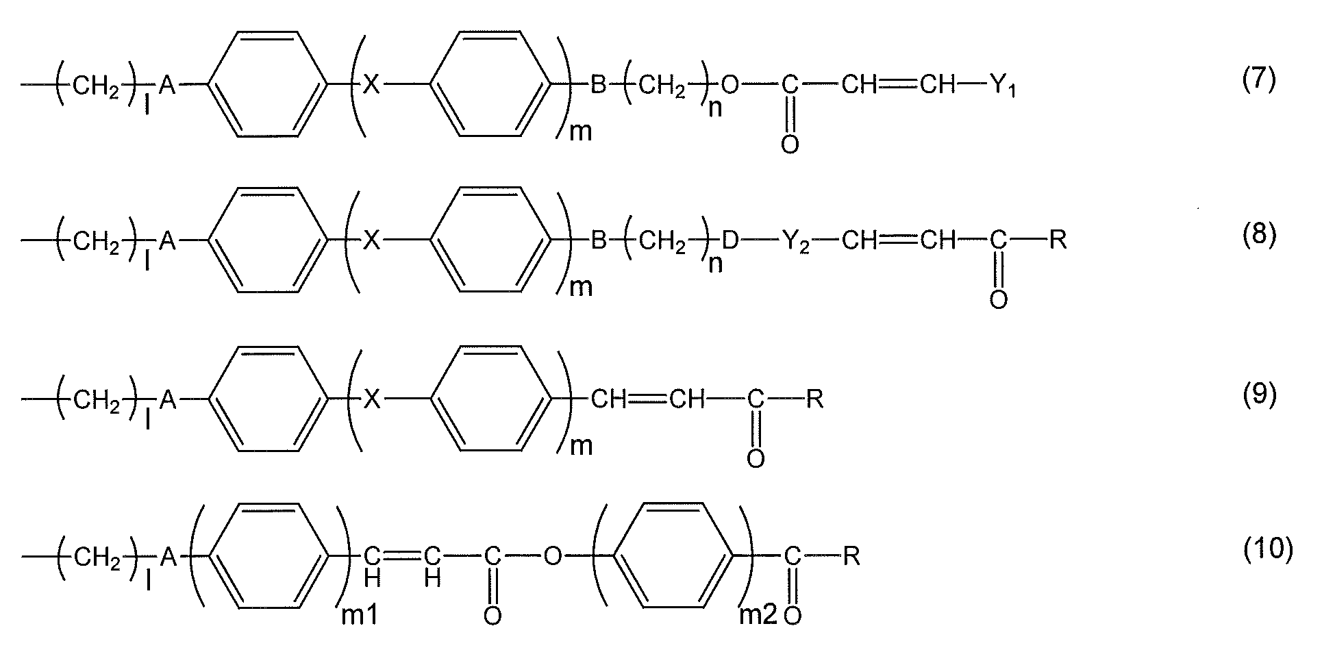
式中、A、X、l、m、m2及びRは、上記と同じ定義を有する。
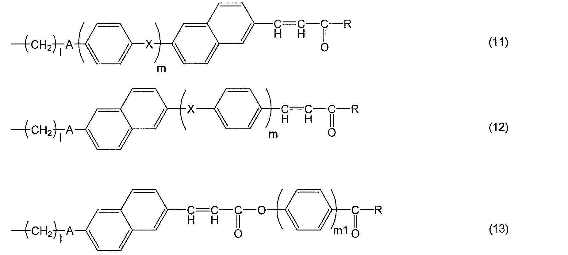
式中、A、Y1、X、l、m1及びm2は上記と同じ定義を有する。
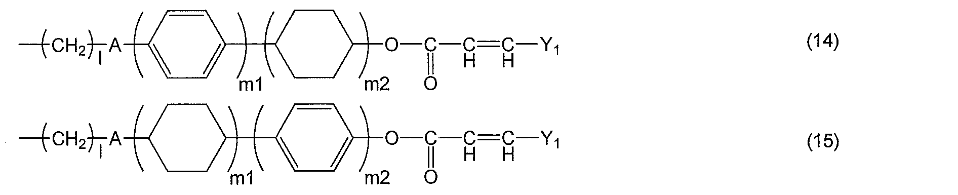
式中、A、X、l及びmは、上記と同じ定義を有する。
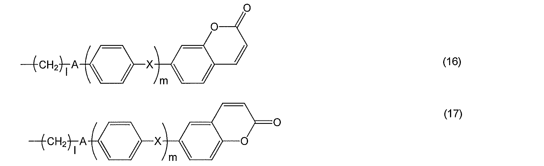
式中、A、B、Y1、q1、q2、m1、及びm2は、上記と同じ定義を有する。
R1は、水素原子、-NO2、-CN、-CH=C(CN)2、-CH=CH-CN、ハロゲン基、炭素数1~5のアルキル基、又は炭素数1~5のアルキルオキシ基を表す。
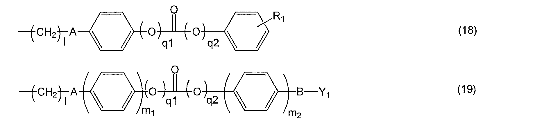
式中、A、Y1、X、l及びmは上記と同じ定義を有する。

式中、A、B、q1及びq2は上記と同じ定義を有する;
Y3は、1価のベンゼン環、ナフタレン環、ビフェニル環、フラン環、窒素含有複素環、及び炭素数5~8の脂環式炭化水素、および、それらの組み合わせからなる群から選ばれる基であり、それらに結合する水素原子はそれぞれ独立に-NO2、-CN、ハロゲン基、炭素数1~5のアルキル基、又は炭素数1~5のアルキルオキシ基で置換されても良い;
R3は、水素原子、-NO2、-CN、-CH=C(CN)2、-CH=CH-CN、ハロゲン基、1価のベンゼン環、ナフタレン環、ビフェニル環、フラン環、窒素含有複素環、炭素数5~8の脂環式炭化水素、炭素数1~12のアルキル基、又は炭素数1~12のアルコキシ基を表す;
lは1~12の整数を表し、mは0から2の整数を表し、但し、式(25)~(26)において、全てのmの合計は2以上であり、式(27)~(28)において、全てのmの合計は1以上であり、m1、m2およびm3は、それぞれ独立に1~3の整数を表す;
R2は、水素原子、-NO2、-CN、ハロゲン基、1価のベンゼン環、ナフタレン環、ビフェニル環、フラン環、窒素含有複素環、及び炭素数5~8の脂環式炭化水素、および、アルキル基、又はアルキルオキシ基を表す;
Z1、Z2は単結合、-CO-、-CH2O-、-CH=N-、-CF2-を表す。

[II] [I]で得られた塗膜に偏光した紫外線を照射する工程;及び
[III] [II]で得られた塗膜を加熱する工程;
を有することによって配向制御能が付与された横電界駆動型液晶表示素子用液晶配向膜を得る、前記液晶配向膜を有する基板の製造方法。
<12> 上記<11>の方法により製造された横電界駆動型液晶表示素子用液晶配向膜を有する基板。
<13> 上記<12>の基板を有する横電界駆動型液晶表示素子。
[I’] 第2の基板上に上記<1>~<10>のいずれかの重合体組成物、特に横電界駆動型液晶表示素子用液晶配向膜製造用組成物を、塗布して塗膜を形成する工程;
[II’] [I’]で得られた塗膜に偏光した紫外線を照射する工程;及び
[III’] [II’]で得られた塗膜を加熱する工程;
を有することによって配向制御能が付与された液晶配向膜を得る、該液晶配向膜を有する第2の基板を得る工程;及び
[IV] 液晶を介して第1及び第2の基板の液晶配向膜が相対するように、第1及び第2の基板を対向配置して液晶表示素子を得る工程;
を有することにより、横電界駆動型液晶表示素子を得る、該液晶表示素子の製造方法。
本発明の方法によって製造された横電界駆動型液晶表示素子は、高効率に配向制御能が付与されているため長時間連続駆動しても表示特性が損なわれることがない。
また、本発明の液晶配向剤は、液晶配向膜の端部の直線性が高く、液晶配向膜の端部の盛り上がりが小さい液晶配向膜を得ることができる。
本発明の製造方法において用いられる重合体組成物は、液晶性を発現し得る感光性の側鎖型高分子(以下、単に側鎖型高分子とも呼ぶ)を有しており、前記重合体組成物を用いて得られる塗膜は、液晶性を発現し得る感光性の側鎖型高分子を有する膜である。この塗膜にはラビング処理を行うこと無く、偏光照射によって配向処理を行う。そして、偏光照射の後、その側鎖型高分子膜を加熱する工程を経て、配向制御能が付与された塗膜(以下、液晶配向膜とも称する)となる。このとき、偏光照射によって発現した僅かな異方性がドライビングフォースとなり、液晶性の側鎖型高分子自体が自己組織化により効率的に再配向する。その結果、液晶配向膜として高効率な配向処理が実現し、高い配向制御能が付与された液晶配向膜を得ることができる。
<液晶配向膜を有する基板の製造方法>及び<液晶表示素子の製造方法>
本発明の液晶配向膜を有する基板の製造方法は、
[I] (A)所定の温度範囲で液晶性を発現する感光性の側鎖型高分子、
(B)ジイソブチルカルビノール、及び
(C)有機溶媒
を含有する重合体組成物を、横電界駆動用の導電膜を有する基板上に塗布して塗膜を形成する工程;
[II] [I]で得られた塗膜に偏光した紫外線を照射する工程;及び
[III] [II]で得られた塗膜を加熱する工程;
を有する。
上記工程により、配向制御能が付与された横電界駆動型液晶表示素子用液晶配向膜を得ることができ、該液晶配向膜を有する基板を得ることができる。
第2の基板は、横電界駆動用の導電膜を有する基板に代わって、横電界駆動用の導電膜を有しない基板を用いる以外、上記工程[I]~[III](横電界駆動用の導電膜を有しない基板を用いるため、便宜上、本願において、工程[I’]~[III’]と略記する場合がある)を用いることにより、配向制御能が付与された液晶配向膜を有する第2の基板を得ることができる。
[IV] 上記で得られた第1及び第2の基板を、液晶を介して第1及び第2の基板の液晶配向膜が相対するように、対向配置して液晶表示素子を得る工程;
を有する。これにより横電界駆動型液晶表示素子を得ることができる。
<工程[I]>
工程[I]では、横電界駆動用の導電膜を有する基板上に、所定の温度範囲で液晶性を発現する感光性の側鎖型高分子、ジイソブチルカルビノール、及び有機溶媒を含有する重合体組成物を塗布して塗膜を形成する。
基板については、特に限定はされないが、製造される液晶表示素子が透過型である場合、透明性の高い基板が用いられることが好ましい。その場合、特に限定はされず、ガラス基板、またはアクリル基板やポリカーボネート基板等のプラスチック基板等を用いることができる。
また、反射型の液晶表示素子への適用を考慮し、シリコンウェハなどの不透明な基板も使用できる。
基板は、横電界駆動用の導電膜を有する。
該導電膜として、液晶表示素子が透過型である場合、ITO(Indium Tin Oxide:酸化インジウムスズ)、IZO(Indium Zinc Oxide:酸化インジウム亜鉛)などを挙げることができるが、これらに限定されない。
また、反射型の液晶表示素子の場合、導電膜として、アルミなどの光を反射する材料などを挙げることができるがこれらに限定されない。
基板に導電膜を形成する方法は、従来公知の手法を用いることができる。
横電界駆動用の導電膜を有する基板上、特に導電膜上に、重合体組成物を塗布する。
本発明の製造方法に用いられる、該重合体組成物は、(A)所定の温度範囲で液晶性を発現する感光性の側鎖型高分子;(B)ジイソブチルカルビノール;及び(C)有機溶媒;を含有する。
(A)成分は、所定の温度範囲で液晶性を発現する感光性の側鎖型高分子である。
(A)側鎖型高分子は、250nm~400nmの波長範囲の光で反応し、かつ100℃~300℃の温度範囲で液晶性を示すのがよい。
(A)側鎖型高分子は、250nm~400nmの波長範囲の光に反応する感光性側鎖を有することが好ましい。
(A)側鎖型高分子は、100℃~300℃の温度範囲で液晶性を示すためメソゲン基を有することが好ましい。

Sは、炭素数1~12のアルキレン基であり、それらに結合する水素原子はハロゲン基に置き換えられていてもよい;
Tは、単結合または炭素数1~12のアルキレン基であり、それらに結合する水素原子はハロゲン基に置き換えられていてもよい;
Y1は、1価のベンゼン環、ナフタレン環、ビフェニル環、フラン環、ピロール環および炭素数5~8の脂環式炭化水素から選ばれる環を表すか、それらの置換基から選ばれる同一又は相異なった2~6の環が結合基Bを介して結合してなる基であり、それらに結合する水素原子はそれぞれ独立に-COOR0(式中、R0は水素原子又は炭素数1~5のアルキル基を表す)、-NO2、-CN、-CH=C(CN)2、-CH=CH-CN、ハロゲン基、炭素数1~5のアルキル基、又は炭素数1~5のアルキルオキシ基で置換されても良い;
Y2は、2価のベンゼン環、ナフタレン環、ビフェニル環、フラン環、ピロール環、炭素数5~8の脂環式炭化水素、および、それらの組み合わせからなる群から選ばれる基であり、それらに結合する水素原子はそれぞれ独立に-NO2、-CN、-CH=C(CN)2、-CH=CH-CN、ハロゲン基、炭素数1~5のアルキル基、又は炭素数1~5のアルキルオキシ基で置換されても良い;
Rは、ヒドロキシ基、炭素数1~6のアルコキシ基を表すか、又はY1と同じ定義を表す;
Xは、単結合、-COO-、-OCO-、-N=N-、-CH=CH-、-C≡C-、-CH=CH-CO-O-、又は-O-CO-CH=CH-を表し、Xの数が2となるときは、X同士は同一でも異なっていてもよい;
Couは、クマリン-6-イル基またはクマリン-7-イル基を表し、それらに結合する水素原子はそれぞれ独立に-NO2、-CN、-CH=C(CN)2、-CH=CH-CN、ハロゲン基、炭素数1~5のアルキル基、又は炭素数1~5のアルキルオキシ基で置換されても良い;
q1とq2は、一方が1で他方が0である;
q3は0または1である;
P及びQは、各々独立に、2価のベンゼン環、ナフタレン環、ビフェニル環、フラン環、ピロール環、炭素数5~8の脂環式炭化水素、および、それらの組み合わせからなる群から選ばれる基である;ただし、Xが-CH=CH-CO-O-、-O-CO-CH=CH-である場合、-CH=CH-が結合する側のP又はQは芳香環であり、Pの数が2以上となるときは、P同士は同一でも異なっていてもよく、Qの数が2以上となるときは、Q同士は同一でも異なっていてもよい;
l1は0または1である;
l2は0~2の整数である;
l1とl2がともに0であるときは、Tが単結合であるときはAも単結合を表す;
l1が1であるときは、Tが単結合であるときはBも単結合を表す;
H及びIは、各々独立に、2価のベンゼン環、ナフタレン環、ビフェニル環、フラン環、ピロール環、およびそれらの組み合わせから選ばれる基である。
式中、A、B、D、Y1、X、Y2、及びRは、上記と同じ定義を有する;
lは1~12の整数を表す;
mは、0~2の整数を表し、m1、m2は1~3の整数を表す;
nは0~12の整数(ただしn=0のときBは単結合である)を表す。

式中、A、X、l、m、m2及びRは、上記と同じ定義を有する。
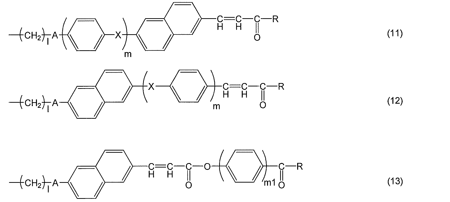
式中、A、Y1、X、l、m1及びm2は上記と同じ定義を有する。
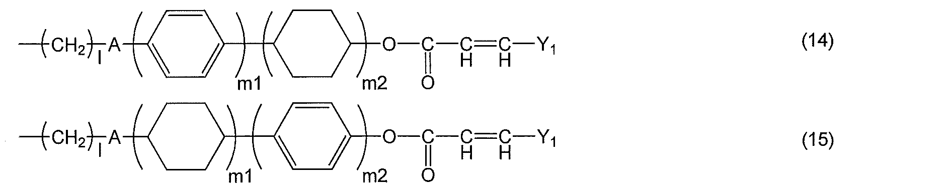
式中、A、X、l及びmは、上記と同じ定義を有する。

式中、A、B、Y1、q1、q2、m1、及びm2は、上記と同じ定義を有する。
R1は、水素原子、-NO2、-CN、-CH=C(CN)2、-CH=CH-CN、ハロゲン基、炭素数1~5のアルキル基、又は炭素数1~5のアルキルオキシ基を表す。

式中、A、Y1、X、l及びmは上記と同じ定義を有する。

式中、A、B、q1及びq2は上記と同じ定義を有する;
Y3は、1価のベンゼン環、ナフタレン環、ビフェニル環、フラン環、窒素含有複素環、及び炭素数5~8の脂環式炭化水素、および、それらの組み合わせからなる群から選ばれる基であり、それらに結合する水素原子はそれぞれ独立に-NO2、-CN、ハロゲン基、炭素数1~5のアルキル基、又は炭素数1~5のアルキルオキシ基で置換されても良い;
R3は、水素原子、-NO2、-CN、-CH=C(CN)2、-CH=CH-CN、ハロゲン基、1価のベンゼン環、ナフタレン環、ビフェニル環、フラン環、窒素含有複素環、炭素数5~8の脂環式炭化水素、炭素数1~12のアルキル基、又は炭素数1~12のアルコキシ基を表す;
lは1~12の整数を表し、mは0から2の整数を表し、但し、式(25)~(26)において、全てのmの合計は2以上であり、式(27)~(28)において、全てのmの合計は1以上であり、m1、m2およびm3は、それぞれ独立に1~3の整数を表す;
R2は、水素原子、-NO2、-CN、ハロゲン基、1価のベンゼン環、ナフタレン環、ビフェニル環、フラン環、窒素含有複素環、及び炭素数5~8の脂環式炭化水素、および、アルキル基、又はアルキルオキシ基を表す;
Z1、Z2は単結合、-CO-、-CH2O-、-CH=N-、-CF2-を表す。
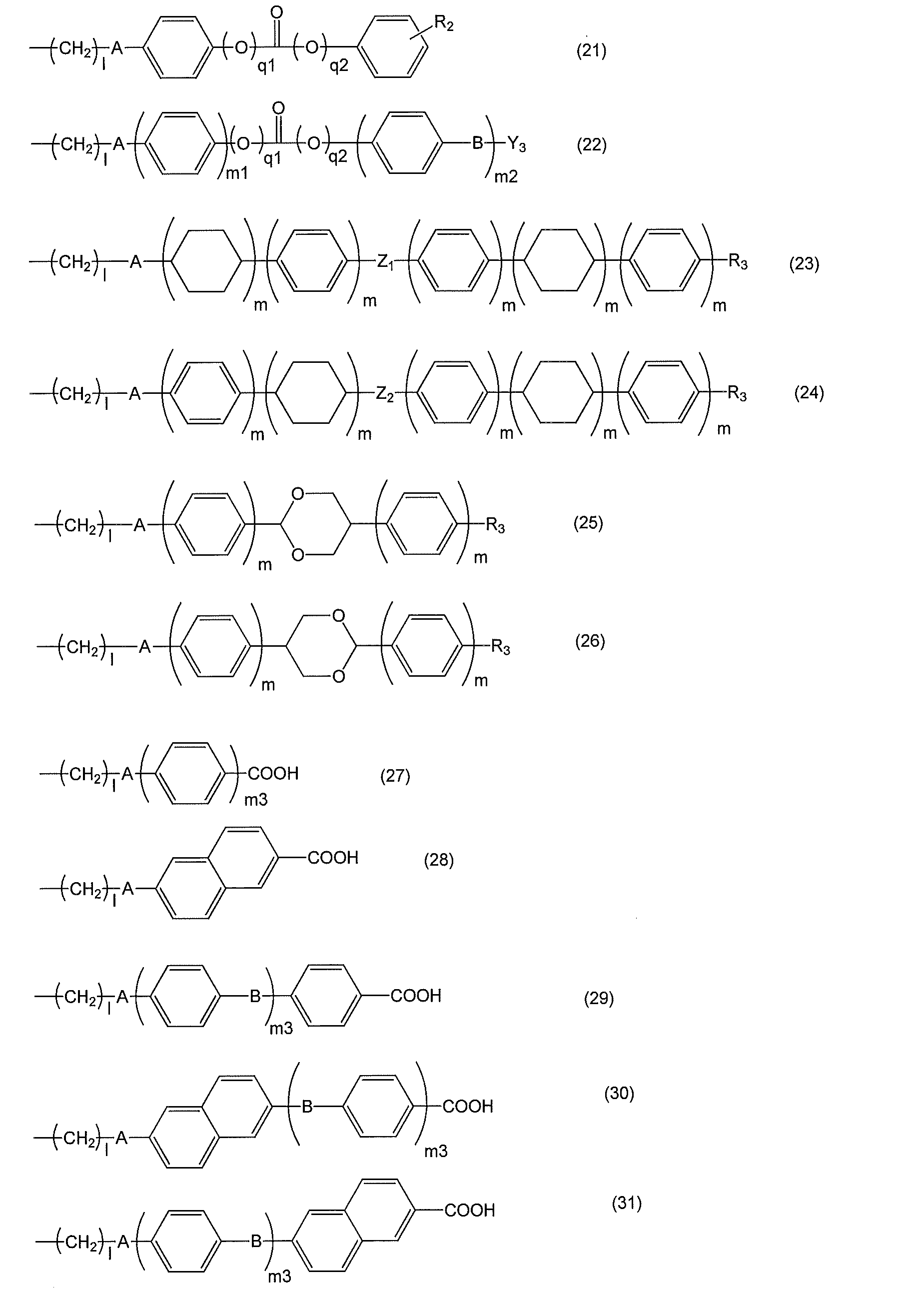
上記の液晶性を発現し得る感光性の側鎖型高分子は、上記の感光性側鎖を有する光反応性側鎖モノマーおよび液晶性側鎖モノマーを重合することによって得ることができる。
光反応性側鎖モノマーとは、高分子を形成した場合に、高分子の側鎖部位に感光性側鎖を有する高分子を形成することができるモノマーのことである。
側鎖の有する光反応性基としては下記の構造およびその誘導体が好ましい。

式中、Rは水素原子またはメチル基を示す;Sは炭素数2~10のアルキレン基を表す;R10はBrまたはCNを示す;Sは炭素数2~10のアルキレン基を表す;uは0または1を表す;及びPyは2-ピリジル基、3-ピリジル基または4-ピリジル基を表す。また、vは1または2を表す。


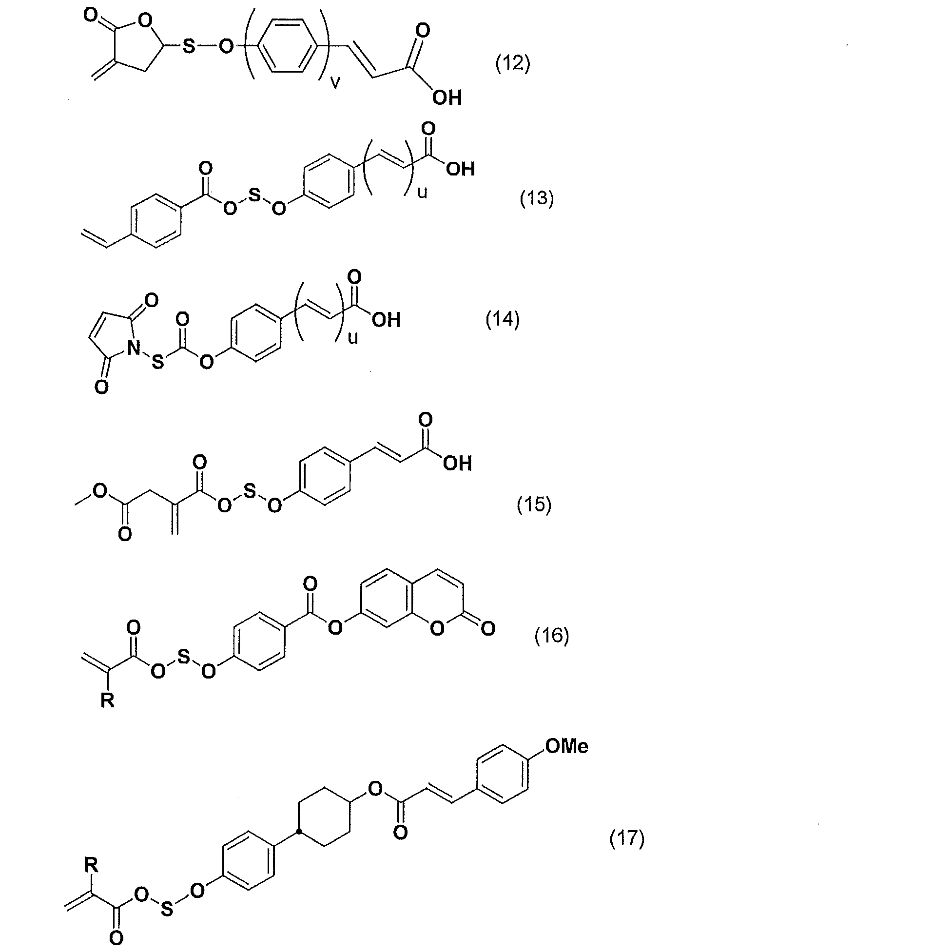
液晶性側鎖モノマーとは、該モノマー由来の高分子が液晶性を発現し、該高分子が側鎖部位にメソゲン基を形成することができるモノマーのことである。
側鎖の有するメソゲン基として、ビフェニルやフェニルベンゾエートなどの単独でメソゲン構造となる基であっても、安息香酸などのように側鎖同士が水素結合することでメソゲン構造となる基であってもよい。側鎖の有するメソゲン基としては下記の構造が好ましい。
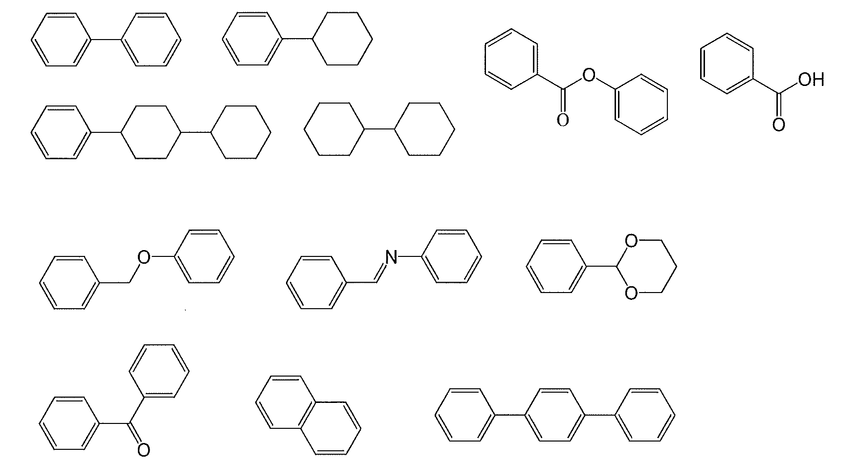
その他のモノマーの具体例としては、不飽和カルボン酸、アクリル酸エステル化合物、メタクリル酸エステル化合物、マレイミド化合物、アクリロニトリル、マレイン酸無水物、スチレン化合物及びビニル化合物等が挙げられる。
アクリル酸エステル化合物としては、例えば、メチルアクリレート、エチルアクリレート、イソプロピルアクリレート、ベンジルアクリレート、ナフチルアクリレート、アントリルアクリレート、アントリルメチルアクリレート、フェニルアクリレート、2,2,2-トリフルオロエチルアクリレート、tert-ブチルアクリレート、シクロヘキシルアクリレート、イソボルニルアクリレート、2-メトキシエチルアクリレート、メトキシトリエチレングリコールアクリレート、2-エトキシエチルアクリレート、テトラヒドロフルフリルアクリレート、3-メトキシブチルアクリレート、2-メチル-2-アダマンチルアクリレート、2-プロピル-2-アダマンチルアクリレート、8-メチル-8-トリシクロデシルアクリレート、及び、8-エチル-8-トリシクロデシルアクリレート等が挙げられる。
スチレン化合物としては、例えば、スチレン、メチルスチレン、クロロスチレン、ブロモスチレン等が挙げられる。
マレイミド化合物としては、例えば、マレイミド、N-メチルマレイミド、N-フェニルマレイミド、及びN-シクロヘキシルマレイミド等が挙げられる。
また、ラジカル重合において有機溶媒中の酸素は重合反応を阻害する原因となるので、有機溶媒は可能な程度に脱気されたものを用いることが好ましい。
上述の反応により得られた、液晶性を発現し得る感光性の側鎖型高分子の反応溶液から、生成した高分子を回収する場合には、反応溶液を貧溶媒に投入して、それら重合体を沈殿させれば良い。沈殿に用いる貧溶媒としては、メタノール、アセトン、ヘキサン、ヘプタン、ブチルセルソルブ、ヘプタン、メチルエチルケトン、メチルイソブチルケトン、エタノール、トルエン、ベンゼン、ジエチルエーテル、メチルエチルエーテル、水等を挙げることができる。貧溶媒に投入して沈殿させた重合体は、濾過して回収した後、常圧あるいは減圧下で、常温あるいは加熱して乾燥することができる。また、沈殿回収した重合体を、有機溶媒に再溶解させ、再沈殿回収する操作を2回~10回繰り返すと、重合体中の不純物を少なくすることができる。この際の貧溶媒として、例えば、アルコール類、ケトン類、炭化水素等が挙げられ、これらの中から選ばれる3種類以上の貧溶媒を用いると、より一層精製の効率が上がるので好ましい。
本発明に用いられる重合体組成物は、液晶配向膜の形成に好適となるように塗布液として調製されることが好ましい。すなわち、本発明に用いられる重合体組成物は、樹脂被膜を形成するための樹脂成分が有機溶媒に溶解した溶液として調製されることが好ましい。ここで、その樹脂成分とは、既に説明した液晶性を発現し得る感光性の側鎖型高分子を含む樹脂成分である。その際、樹脂成分の含有量は、1質量%~20質量%が好ましく、より好ましくは3質量%~15質量%、特に好ましくは3質量%~10質量%である。
そのような他の重合体は、例えば、ポリ(メタ)アクリレートやポリアミック酸やポリイミド等からなり、液晶性を発現し得る感光性の側鎖型高分子ではない重合体等が挙げられる。
本発明に用いられる重合体組成物は、(B)成分として、下記構造式で表されるジイソブチルカルビノール、すなわち、2,6-ジメチル-4-ヘプタノールを含有する。

含有量は、(C)成分の有機溶媒100質量部に対して、好ましくは20~60質量部、さらに好ましくは25~45質量部である。
本発明に用いられる重合体組成物に用いる有機溶媒は、樹脂成分を溶解させる有機溶媒であれば特に限定されない。その具体例を以下に挙げる。
N,N-ジメチルホルムアミド、N,N-ジメチルアセトアミド、N-メチル-2-ピロリドン、N-メチルカプロラクタム、2-ピロリドン、N-エチルピロリドン、N-ビニルピロリドン、ジメチルスルホキシド、テトラメチル尿素、ピリジン、ジメチルスルホン、ヘキサメチルスルホキシド、γ-ブチロラクトン、3-メトキシ-N,N-ジメチルプロパンアミド、3-エトキシ-N,N-ジメチルプロパンアミド、3-ブトキシ-N,N-ジメチルプロパンアミド、1,3-ジメチル-イミダゾリジノン、エチルアミルケトン、メチルノニルケトン、メチルエチルケトン、メチルイソアミルケトン、メチルイソプロピルケトン、シクロヘキサノン、エチレンカーボネート、プロピレンカーボネート、ジグライム、4-ヒドロキシ-4-メチル-2-ペンタノン、プロピレングリコールモノアセテート、プロピレングリコールモノメチルエーテル、プロピレングリコール-tert-ブチルエーテル、ジプロピレングリコールモノメチルエーテル、ジエチレングリコール、ジエチレングリコールモノアセテート、ジエチレングリコールジメチルエーテル、ジプロピレングリコールモノアセテートモノメチルエーテル、ジプロピレングリコールモノメチルエーテル、ジプロピレングリコールモノエチルエーテル、ジプロピレングリコールモノアセテートモノエチルエーテル、ジプロピレングリコールモノプロピルエーテル、ジプロピレングリコールモノアセテートモノプロピルエーテル、3-メチル-3-メトキシブチルアセテート、トリプロピレングリコールメチルエーテル等が挙げられる。これらは単独で使用しても、混合して使用してもよい。
例えば、イソプロピルアルコール、メトキシメチルペンタノール、メチルセロソルブ、エチルセロソルブ、ブチルセロソルブ、メチルセロソルブアセテート、エチルセロソルブアセテート、ブチルカルビトール、エチルカルビトール、エチルカルビトールアセテート、エチレングリコール、エチレングリコールモノアセテート、エチレングリコールモノイソプロピルエーテル、エチレングリコールモノブチルエーテル、プロピレングリコール、プロピレングリコールモノアセテート、プロピレングリコールモノメチルエーテル、プロピレングリコールモノn-ブチルエーテル、プロピレングリコール-tert-ブチルエーテル、ジプロピレングリコールモノメチルエーテル、ジエチレングリコール、ジエチレングリコールモノアセテート、ジエチレングリコールジメチルエーテル、ジプロピレングリコールモノアセテートモノメチルエーテル、ジプロピレングリコールモノメチルエーテル、ジプロピレングリコールモノエチルエーテル、ジプロピレングリコールモノアセテートモノエチルエーテル、ジプロピレングリコールモノプロピルエーテル、ジプロピレングリコールモノアセテートモノプロピルエーテル、3-メチル-3-メトキシブチルアセテート、トリプロピレングリコールメチルエーテル、3-メチル-3-メトキシブタノール、ジイソプロピルエーテル、エチルイソブチルエーテル、ジイソブチレン、アミルアセテート、ブチルブチレート、ブチルエーテル、ジイソブチルケトン、メチルシクロへキセン、プロピルエーテル、ジヘキシルエーテル、1-ヘキサノール、n-へキサン、n-ペンタン、n-オクタン、ジエチルエーテル、乳酸メチル、乳酸エチル、酢酸メチル、酢酸エチル、酢酸n-ブチル、酢酸プロピレングリコールモノエチルエーテル、ピルビン酸メチル、ピルビン酸エチル、3-メトキシプロピオン酸メチル、3-エトキシプロピオン酸メチルエチル、3-メトキシプロピオン酸エチル、3-エトキシプロピオン酸、3-メトキシプロピオン酸、3-メトキシプロピオン酸プロピル、3-メトキシプロピオン酸ブチル、1-メトキシ-2-プロパノール、1-エトキシ-2-プロパノール、1-ブトキシ-2-プロパノール、1-フェノキシ-2-プロパノール、プロピレングリコールモノアセテート、プロピレングリコールジアセテート、プロピレングリコール-1-モノメチルエーテル-2-アセテート、プロピレングリコール-1-モノエチルエーテル-2-アセテート、ジプロピレングリコール、2-(2-エトキシプロポキシ)プロパノール、乳酸メチルエステル、乳酸エチルエステル、乳酸n-プロピルエステル、乳酸n-ブチルエステル、乳酸イソアミルエステル等の低表面張力を有する溶媒等が挙げられる。
より具体的には、例えば、エフトップ(登録商標)301、EF303、EF352(トーケムプロダクツ社製)、メガファック(登録商標)F171、F173、R-30(DIC社製)、フロラードFC430、FC431(住友スリーエム社製)、アサヒガード(登録商標)AG710(旭硝子社製)、サーフロン(登録商標)S-382、SC101、SC102、SC103、SC104、SC105、SC106(AGCセイミケミカル社製)等が挙げられる。これらの界面活性剤の使用割合は、重合体組成物に含有される樹脂成分の100質量部に対して、好ましくは0.01質量部~2質量部、より好ましくは0.01質量部~1質量部である。
例えば、3-アミノプロピルトリメトキシシラン、3-アミノプロピルトリエトキシシラン、2-アミノプロピルトリメトキシシラン、2-アミノプロピルトリエトキシシラン、N-(2-アミノエチル)-3-アミノプロピルトリメトキシシラン、N-(2-アミノエチル)-3-アミノプロピルメチルジメトキシシラン、3-ウレイドプロピルトリメトキシシラン、3-ウレイドプロピルトリエトキシシラン、N-エトキシカルボニル-3-アミノプロピルトリメトキシシラン、N-エトキシカルボニル-3-アミノプロピルトリエトキシシラン、N-トリエトキシシリルプロピルトリエチレントリアミン、N-トリメトキシシリルプロピルトリエチレントリアミン、10-トリメトキシシリル-1,4,7-トリアザデカン、10-トリエトキシシリル-1,4,7-トリアザデカン、9-トリメトキシシリル-3,6-ジアザノニルアセテート、9-トリエトキシシリル-3,6-ジアザノニルアセテート、N-ベンジル-3-アミノプロピルトリメトキシシラン、N-ベンジル-3-アミノプロピルトリエトキシシラン、N-フェニル-3-アミノプロピルトリメトキシシラン、N-フェニル-3-アミノプロピルトリエトキシシラン、N-ビス(オキシエチレン)-3-アミノプロピルトリメトキシシラン、N-ビス(オキシエチレン)-3-アミノプロピルトリエトキシシラン等が挙げられる。
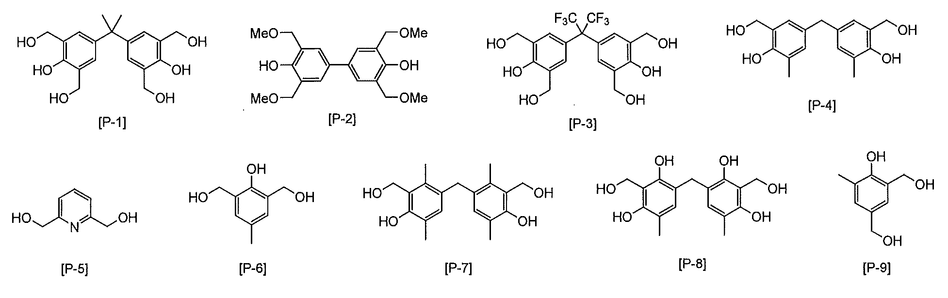
光増感剤としては、芳香族ニトロ化合物、クマリン(7-ジエチルアミノ-4-メチルクマリン、7-ヒドロキシ4-メチルクマリン)、ケトクマリン、カルボニルビスクマリン、芳香族2-ヒドロキシケトン、およびアミノ置換された、芳香族2-ヒドロキシケトン(2-ヒドロキシベンゾフェノン、モノ-もしくはジ-p-(ジメチルアミノ)-2-ヒドロキシベンゾフェノン)、アセトフェノン、アントラキノン、キサントン、チオキサントン、ベンズアントロン、チアゾリン(2-ベンゾイルメチレン-3-メチル-β-ナフトチアゾリン、2-(β-ナフトイルメチレン)-3-メチルベンゾチアゾリン、2-(α-ナフトイルメチレン)-3-メチルベンゾチアゾリン、2-(4-ビフェノイルメチレン)-3-メチルベンゾチアゾリン、2-(β-ナフトイルメチレン)-3-メチル-β-ナフトチアゾリン、2-(4-ビフェノイルメチレン)-3-メチル-β-ナフトチアゾリン、2-(p-フルオロベンゾイルメチレン)-3-メチル-β-ナフトチアゾリン)、オキサゾリン(2-ベンゾイルメチレン-3-メチル-β-ナフトオキサゾリン、2-(β-ナフトイルメチレン)-3-メチルベンゾオキサゾリン、2-(α-ナフトイルメチレン)-3-メチルベンゾオキサゾリン、2-(4-ビフェノイルメチレン)-3-メチルベンゾオキサゾリン、2-(β-ナフトイルメチレン)-3-メチル-β-ナフトオキサゾリン、2-(4-ビフェノイルメチレン)-3-メチル-β-ナフトオキサゾリン、2-(p-フルオロベンゾイルメチレン)-3-メチル-β-ナフトオキサゾリン)、ベンゾチアゾール、ニトロアニリン(m-もしくはp-ニトロアニリン、2,4,6-トリニトロアニリン)またはニトロアセナフテン(5-ニトロアセナフテン)、(2-[(m-ヒドロキシ-p-メトキシ)スチリル]ベンゾチアゾール、ベンゾインアルキルエーテル、N-アルキル化フタロン、アセトフェノンケタール(2,2-ジメトキシフェニルエタノン)、ナフタレン、アントラセン(2-ナフタレンメタノール、2-ナフタレンカルボン酸、9-アントラセンメタノール、および9-アントラセンカルボン酸)、ベンゾピラン、アゾインドリジン、メロクマリン等がある。
好ましくは、芳香族2-ヒドロキシケトン(ベンゾフェノン)、クマリン、ケトクマリン、カルボニルビスクマリン、アセトフェノン、アントラキノン、キサントン、チオキサントン、およびアセトフェノンケタールである。
塗布方法は、工業的には、スクリーン印刷、オフセット印刷、フレキソ印刷またはインクジェット法などで行う方法が一般的である。その他の塗布方法としては、ディップ法、ロールコータ法、スリットコータ法、スピンナ法(回転塗布法)またはスプレー法などがあり、目的に応じてこれらを用いてもよい。
塗膜の厚みは、厚すぎると液晶表示素子の消費電力の面で不利となり、薄すぎると液晶表示素子の信頼性が低下する場合があるので、好ましくは5nm~300nm、より好ましくは10nm~150nmである。
尚、[I]工程の後、続く[II]工程の前に塗膜の形成された基板を室温にまで冷却する工程を設けることも可能である。
工程[II]では、工程[I]で得られた塗膜に偏光した紫外線を照射する。塗膜の膜面に偏光した紫外線を照射する場合、基板に対して一定の方向から偏光板を介して偏光された紫外線を照射する。使用する紫外線としては、波長100nm~400nmの範囲の紫外線を使用することができる。好ましくは、使用する塗膜の種類によりフィルター等を介して最適な波長を選択する。そして、例えば、選択的に光架橋反応を誘起できるように、波長290nm~400nmの範囲の紫外線を選択して使用することができる。紫外線としては、例えば、高圧水銀灯から放射される光を用いることができる。
工程[III]では、工程[II]で偏光した紫外線の照射された塗膜を加熱する。加熱により、塗膜に配向制御能を付与することができる。
加熱は、ホットプレート、熱循環型オーブンまたはIR(赤外線)型オーブンなどの加熱手段を用いることができる。加熱温度は、使用する塗膜の液晶性を発現させる温度を考慮して決めることができる。
なお、液晶発現温度は、側鎖型高分子または塗膜表面が固体相から液晶相に相転移がおきるガラス転移温度(Tg)以上であって、液晶相からアイソトロピック相(等方相)に相転移を起こすアイソトロピック相転移温度(Tiso)以下の温度をいう。
[IV]工程は、[III]で得られた、横電界駆動用の導電膜上に液晶配向膜を有する基板(第1の基板)と、同様に上記[I’]~[III’]で得られた、導電膜を有しない液晶配向膜付基板(第2の基板)とを、液晶を介して、双方の液晶配向膜が相対するように対向配置して、公知の方法で液晶セルを作製し、横電界駆動型液晶表示素子を作製する工程である。なお、工程[I’]~[III’]は、工程[I]において、横電界駆動用の導電膜を有する基板の代わりに、該横電界駆動用導電膜を有しない基板を用いた以外、工程[I]~[III]と同様に行うことができる。工程[I]~[III]と工程[I’]~[III’]との相違点は、上述した導電膜の有無だけであるため、工程[I’]~[III’]の説明を省略する。
本発明に用いる塗膜では、側鎖の光反応と液晶性に基づく自己組織化によって誘起される分子再配向の原理を利用して、塗膜への高効率な異方性の導入を実現する。本発明の製造方法では、側鎖型高分子に光反応性基として光架橋性基を有する構造の場合、側鎖型高分子を用いて基板上に塗膜を形成した後、偏光した紫外線を照射し、次いで、加熱を行った後、液晶表示素子を作成する。
以下、実施例を用いて本発明を説明するが、本発明は、該実施例に限定されるものではない。
(メタクリルモノマー)

THF:テトラヒドロフラン
NEP:N-エチル-2-ピロリドン
PB:プロピレングリコールモノブチルエーテル
DIBC:2,6-ジメチル-4-ヘプタノール
<重合開始剤>
AIBN:2,2’-アゾビスイソブチロニトリル
MA1(9.97g、30.0mmol)をTHF(92.0g)中に溶解し、ダイアフラムポンプで脱気を行った後、AIBN(0.246g、1.5mmol)を加え再び脱気を行った。この後50℃で30時間反応させメタクリレートのポリマー溶液を得た。このポリマー溶液をジエチルエーテル(1000ml)に滴下し、得られた沈殿物をろ過した。この沈澱物をジエチルエーテルで洗浄し、40℃のオーブン中で減圧乾燥しメタクリレートポリマー粉末(A)を得た。このポリマーの数平均分子量は16000、重量平均分子量は32000であった。
得られたメタクリレートポリマーの液晶相転移温度は145℃~190℃であった。
得られたメタクリレートポリマー粉末(A)(6.0g)にNEP(49.0g)を加え、室温で5時間攪拌して溶解させた。この溶液にPB(20.0g)およびDIBC(25.0g)を加え攪拌することにより液晶配向剤(A1)を得た。
得られたメタクリレートポリマー粉末(A)(6.0g)にNEP(49.0g)を加え、室温で5時間攪拌して溶解させた。この溶液にPB(10.0g)およびDIBC(35.0g)を加え攪拌することにより液晶配向剤(A2)を得た。
得られたメタクリレートポリマー粉末(A)(6.0g)にNEP(49.0g)を加え、室温で5時間攪拌して溶解させた。この溶液にDIBC(45.0g)を加え攪拌することにより液晶配向剤(A3)を得た。
得られたメタクリレートポリマー粉末(A)(6.0g)にNEP(49.0g)を加え、室温で5時間攪拌して溶解させた。この溶液にPB(45.0g)を加え攪拌することにより液晶配向剤(コントロール1)を得た。
インクジェット塗布機としては、HIS-200(日立プラントテクノロジー社製)を用いた。塗布は、純水およびIPA(イソプロピルアルコール)にて洗浄を行ったITO(酸化インジウムスズ)蒸着基板上に、塗布面積が80×72mm、ノズルピッチが0.423mm、スキャンピッチが0.5mm、塗布速度が40mm/秒、塗布から仮乾燥までの時間が30秒、仮乾燥がホットプレート上にて70℃で90秒間の条件で行った。

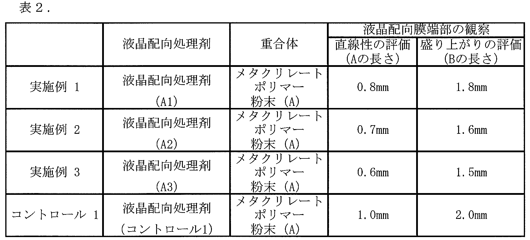
1 側鎖型高分子膜
2、2a 側鎖
図2
3 側鎖型高分子膜
4、4a 側鎖
図3
5 側鎖型高分子膜
6、6a 側鎖
図4
7 側鎖型高分子膜
8、8a 側鎖
図5
9 液晶配向膜
10 ITO(酸化インジウムスズ)蒸着基板
図6
11 液晶配向膜
12 ITO(酸化インジウムスズ)蒸着基板
Claims (15)
- (A)所定の温度範囲で液晶性を発現する感光性の側鎖型高分子、
(B)ジイソブチルカルビノール、及び
(C)有機溶媒
を含有する、重合体組成物。 - (A)成分が、光架橋、光異性化、または光フリース転移を起こす感光性側鎖を有する請求項1に記載の組成物。
- (A)成分が、下記式(1)~(6)
(式中、A、B、Dはそれぞれ独立に、単結合、-O-、-CH2-、-COO-、-OCO-、-CONH-、-NH-CO-、-CH=CH-CO-O-、又は-O-CO-CH=CH-を表す;
Sは、炭素数1~12のアルキレン基であり、それらに結合する水素原子はハロゲン基に置き換えられていてもよい;
Tは、単結合または炭素数1~12のアルキレン基であり、それらに結合する水素原子はハロゲン基に置き換えられていてもよい;
Y1は、1価のベンゼン環、ナフタレン環、ビフェニル環、フラン環、ピロール環および炭素数5~8の脂環式炭化水素から選ばれる環を表すか、それらの置換基から選ばれる同一又は相異なった2~6の環が結合基Bを介して結合してなる基であり、それらに結合する水素原子はそれぞれ独立に-COOR0(式中、R0は水素原子又は炭素数1~5のアルキル基を表す)、-NO2、-CN、-CH=C(CN)2、-CH=CH-CN、ハロゲン基、炭素数1~5のアルキル基、又は炭素数1~5のアルキルオキシ基で置換されても良い;
Y2は、2価のベンゼン環、ナフタレン環、ビフェニル環、フラン環、ピロール環、炭素数5~8の脂環式炭化水素、および、それらの組み合わせからなる群から選ばれる基であり、それらに結合する水素原子はそれぞれ独立に-NO2、-CN、-CH=C(CN)2、-CH=CH-CN、ハロゲン基、炭素数1~5のアルキル基、又は炭素数1~5のアルキルオキシ基で置換されても良い;
Rは、ヒドロキシ基、炭素数1~6のアルコキシ基を表すか、又はY1と同じ定義を表す;
Xは、単結合、-COO-、-OCO-、-N=N-、-CH=CH-、-C≡C-、-CH=CH-CO-O-、又は-O-CO-CH=CH-を表し、Xの数が2となるときは、X同士は同一でも異なっていてもよい;
Couは、クマリン-6-イル基またはクマリン-7-イル基を表し、それらに結合する水素原子はそれぞれ独立に-NO2、-CN、-CH=C(CN)2、-CH=CH-CN、ハロゲン基、炭素数1~5のアルキル基、又は炭素数1~5のアルキルオキシ基で置換されても良い;
q1とq2は、一方が1で他方が0である;
q3は0または1である;
P及びQは、各々独立に、2価のベンゼン環、ナフタレン環、ビフェニル環、フラン環、ピロール環、炭素数5~8の脂環式炭化水素、および、それらの組み合わせからなる群から選ばれる基である;ただし、Xが-CH=CH-CO-O-、-O-CO-CH=CH-である場合、-CH=CH-が結合する側のP又はQは芳香環であり、Pの数が2以上となるときは、P同士は同一でも異なっていてもよく、Qの数が2以上となるときは、Q同士は同一でも異なっていてもよい;
l1は0または1である;
l2は0~2の整数である;
l1とl2がともに0であるときは、Tが単結合であるときはAも単結合を表す;
l1が1であるときは、Tが単結合であるときはBも単結合を表す;
H及びIは、各々独立に、2価のベンゼン環、ナフタレン環、ビフェニル環、フラン環、ピロール環、およびそれらの組み合わせから選ばれる基である。)
からなる群から選ばれるいずれか1種の感光性側鎖を有する請求項1または2に記載の組成物。

- (A)成分が、下記式(7)~(10)
(式中、A、B、Dはそれぞれ独立に、単結合、-O-、-CH2-、-COO-、-OCO-、-CONH-、-NH-CO-、-CH=CH-CO-O-、又は-O-CO-CH=CH-を表す;
Y1は、1価のベンゼン環、ナフタレン環、ビフェニル環、フラン環、ピロール環および炭素数5~8の脂環式炭化水素から選ばれる環を表すか、それらの置換基から選ばれる同一又は相異なった2~6の環が結合基Bを介して結合してなる基であり、それらに結合する水素原子はそれぞれ独立に-COOR0(式中、R0は水素原子又は炭素数1~5のアルキル基を表す)、-NO2、-CN、-CH=C(CN)2、-CH=CH-CN、ハロゲン基、炭素数1~5のアルキル基、又は炭素数1~5のアルキルオキシ基で置換されても良い;
Xは、単結合、-COO-、-OCO-、-N=N-、-CH=CH-、-C≡C-、-CH=CH-CO-O-、又は-O-CO-CH=CH-を表し、Xの数が2となるときは、X同士は同一でも異なっていてもよい;
lは1~12の整数を表す;
mは、0~2の整数を表し、m1、m2は1~3の整数を表す;
nは0~12の整数(ただしn=0のときBは単結合である)を表す;
Y2は、2価のベンゼン環、ナフタレン環、ビフェニル環、フラン環、ピロール環、炭素数5~8の脂環式炭化水素、および、それらの組み合わせからなる群から選ばれる基であり、それらに結合する水素原子はそれぞれ独立に-NO2、-CN、-CH=C(CN)2、-CH=CH-CN、ハロゲン基、炭素数1~5のアルキル基、又は炭素数1~5のアルキルオキシ基で置換されても良い;
Rは、ヒドロキシ基、炭素数1~6のアルコキシ基を表すか、又はY1と同じ定義を表す)
からなる群から選ばれるいずれか1種の感光性側鎖を有する請求項1~3のいずれか1項に記載の組成物。
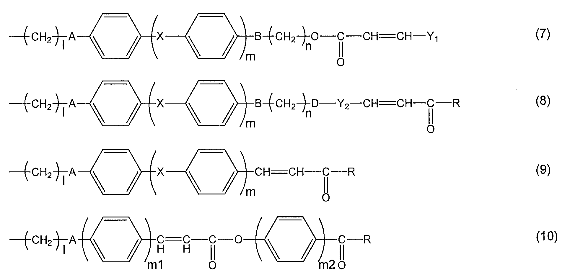
- (A)成分が、下記式(11)~(13)
(式中、Aは、それぞれ独立に、単結合、-O-、-CH2-、-COO-、-OCO-、-CONH-、-NH-CO-、-CH=CH-CO-O-、又は-O-CO-CH=CH-を表す;
Xは、単結合、-COO-、-OCO-、-N=N-、-CH=CH-、-C≡C-、-CH=CH-CO-O-、又は-O-CO-CH=CH-を表し、Xの数が2となるときは、X同士は同一でも異なっていてもよい;
lは、1~12の整数を表し、mは0~2の整数を表し、m2は1~3の整数を表す;
Rは、1価のベンゼン環、ナフタレン環、ビフェニル環、フラン環、ピロール環および炭素数5~8の脂環式炭化水素から選ばれる環を表すか、それらの置換基から選ばれる同一又は相異なった2~6の環が結合基Bを介して結合してなる基であり、それらに結合する水素原子はそれぞれ独立に-COOR0(式中、R0は水素原子又は炭素数1~5のアルキル基を表す)、-NO2、-CN、-CH=C(CN)2、-CH=CH-CN、ハロゲン基、炭素数1~5のアルキル基、又は炭素数1~5のアルキルオキシ基で置換されても良いか、又はヒドロキシ基もしくは炭素数1~6のアルコキシ基を表す)
からなる群から選ばれるいずれか1種の感光性側鎖を有する請求項1~3のいずれか1項に記載の組成物。
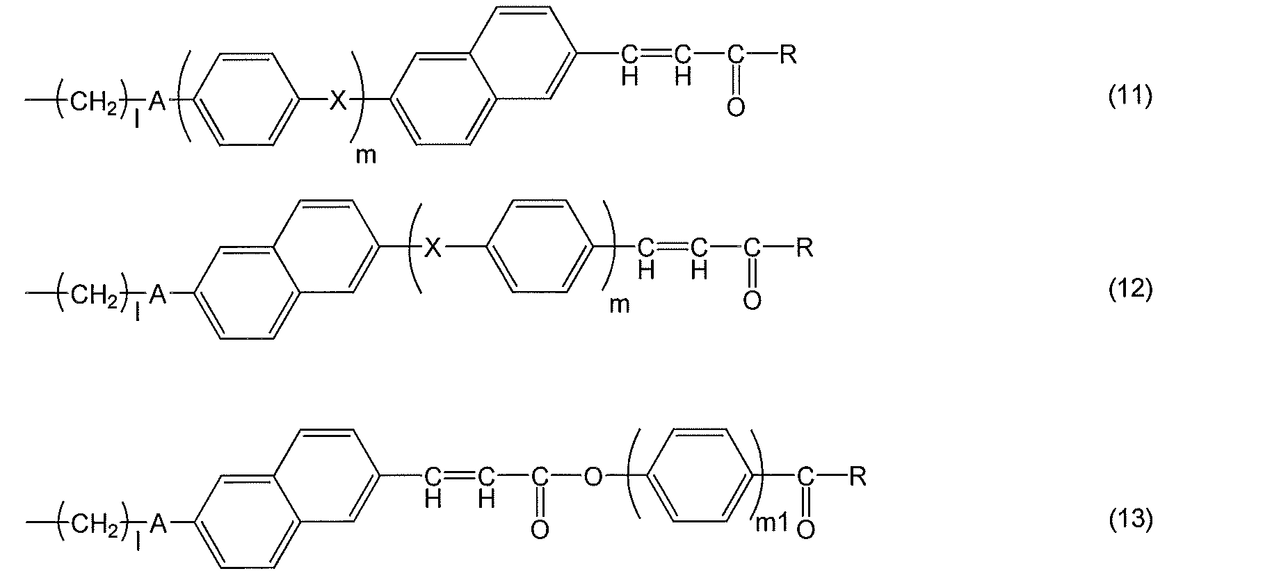
- (A)成分が、下記式(14)又は(15)
(式中、Aはそれぞれ独立に、単結合、-O-、-CH2-、-COO-、-OCO-、-CONH-、-NH-CO-、-CH=CH-CO-O-、又は-O-CO-CH=CH-を表す;
Y1は、1価のベンゼン環、ナフタレン環、ビフェニル環、フラン環、ピロール環および炭素数5~8の脂環式炭化水素から選ばれる環を表すか、それらの置換基から選ばれる同一又は相異なった2~6の環が結合基Bを介して結合してなる基であり、それらに結合する水素原子はそれぞれ独立に-COOR0(式中、R0は水素原子又は炭素数1~5のアルキル基を表す)、-NO2、-CN、-CH=C(CN)2、-CH=CH-CN、ハロゲン基、炭素数1~5のアルキル基、又は炭素数1~5のアルキルオキシ基で置換されても良い;
Xは、単結合、-COO-、-OCO-、-N=N-、-CH=CH-、-C≡C-、-CH=CH-CO-O-、又は-O-CO-CH=CH-を表し、Xの数が2となるときは、X同士は同一でも異なっていてもよい;
lは1~12の整数を表し、m1、m2は1~3の整数を表す)
で表される感光性側鎖を有する請求項1~3のいずれか1項に記載の組成物。
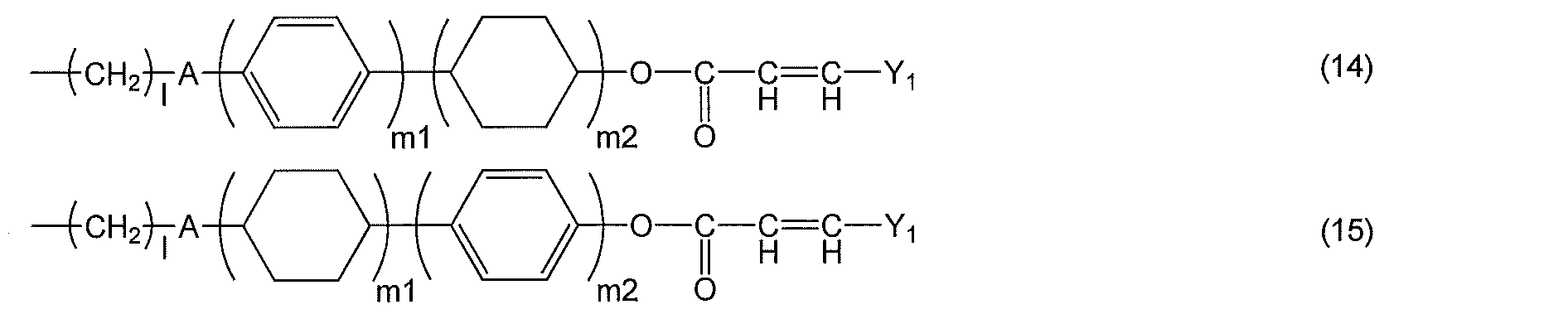
- (A)成分が、下記式(16)又は(17)(式中、Aは単結合、-O-、-CH2-、-COO-、-OCO-、-CONH-、-NH-CO-、-CH=CH-CO-O-、又は-O-CO-CH=CH-を表す;
Xは、単結合、-COO-、-OCO-、-N=N-、-CH=CH-、-C≡C-、-CH=CH-CO-O-、又は-O-CO-CH=CH-を表し、Xの数が2となるときは、X同士は同一でも異なっていてもよい;
lは、1~12の整数を表し、mは0~2の整数を表す)
で表される感光性側鎖を有する請求項1~3のいずれか1項に記載の組成物。
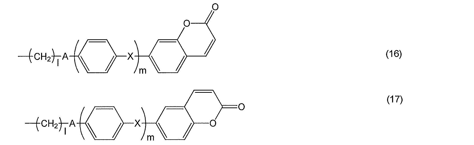
- (A)成分が、下記式(18)又は(19)
(式中、A、Bはそれぞれ独立に、単結合、-O-、-CH2-、-COO-、-OCO-、-CONH-、-NH-CO-、-CH=CH-CO-O-、又は-O-CO-CH=CH-を表す;
Y1は、1価のベンゼン環、ナフタレン環、ビフェニル環、フラン環、ピロール環および炭素数5~8の脂環式炭化水素から選ばれる環を表すか、それらの置換基から選ばれる同一又は相異なった2~6の環が結合基Bを介して結合してなる基であり、それらに結合する水素原子はそれぞれ独立に-COOR0(式中、R0は水素原子又は炭素数1~5のアルキル基を表す)、-NO2、-CN、-CH=C(CN)2、-CH=CH-CN、ハロゲン基、炭素数1~5のアルキル基、又は炭素数1~5のアルキルオキシ基で置換されても良い;
q1とq2は、一方が1で他方が0である;
lは1~12の整数を表し、m1、m2は1~3の整数を表す;
R1は、水素原子、-NO2、-CN、-CH=C(CN)2、-CH=CH-CN、ハロゲン基、炭素数1~5のアルキル基、又は炭素数1~5のアルキルオキシ基を表す)からなる群から選ばれるいずれか1種の感光性側鎖を有する請求項1~3のいずれか1項に記載の組成物。

- (A)成分が、下記式(20)(式中、Aは、単結合、-O-、-CH2-、-COO-、-OCO-、-CONH-、-NH-CO-、-CH=CH-CO-O-、又は-O-CO-CH=CH-を表す;
Y1は、1価のベンゼン環、ナフタレン環、ビフェニル環、フラン環、ピロール環および炭素数5~8の脂環式炭化水素から選ばれる環を表すか、それらの置換基から選ばれる同一又は相異なった2~6の環が結合基Bを介して結合してなる基であり、それらに結合する水素原子はそれぞれ独立に-COOR0(式中、R0は水素原子又は炭素数1~5のアルキル基を表す)、-NO2、-CN、-CH=C(CN)2、-CH=CH-CN、ハロゲン基、炭素数1~5のアルキル基、又は炭素数1~5のアルキルオキシ基で置換されても良い;
Xは、単結合、-COO-、-OCO-、-N=N-、-CH=CH-、-C≡C-、-CH=CH-CO-O-、又は-O-CO-CH=CH-を表し、Xの数が2となるときは、X同士は同一でも異なっていてもよい;
lは1~12の整数を表し、mは0~2の整数を表す)で表される感光性側鎖を有する請求項1~3のいずれか1項に記載の組成物。

- (A)成分が、下記式(21)~(31)(式中、A及びBは上記と同じ定義を有する;
Y3は、1価のベンゼン環、ナフタレン環、ビフェニル環、フラン環、窒素含有複素環、及び炭素数5~8の脂環式炭化水素、および、それらの組み合わせからなる群から選ばれる基であり、それらに結合する水素原子はそれぞれ独立に-NO2、-CN、ハロゲン基、炭素数1~5のアルキル基、又は炭素数1~5のアルキルオキシ基で置換されても良い;
R3は、水素原子、-NO2、-CN、-CH=C(CN)2、-CH=CH-CN、ハロゲン基、1価のベンゼン環、ナフタレン環、ビフェニル環、フラン環、窒素含有複素環、炭素数5~8の脂環式炭化水素、炭素数1~12のアルキル基、又は炭素数1~12のアルコキシ基を表す;
q1とq2は、一方が1で他方が0である;
lは1~12の整数を表し、mは0から2の整数を表し、但し、式(25)~(26)において、全てのmの合計は2以上であり、式(27)~(28)において、全てのmの合計は1以上であり、m1、m2およびm3は、それぞれ独立に1~3の整数を表す;
R2は、水素原子、-NO2、-CN、ハロゲン基、1価のベンゼン環、ナフタレン環、ビフェニル環、フラン環、窒素含有複素環、及び炭素数5~8の脂環式炭化水素、および、アルキル基、又はアルキルオキシ基を表す;
Z1、Z2は単結合、-CO-、-CH2O-、-CH=N-、-CF2-を表す)からなる群から選ばれるいずれか1種の液晶性側鎖を有する請求項1~9のいずれか1項に記載の組成物。
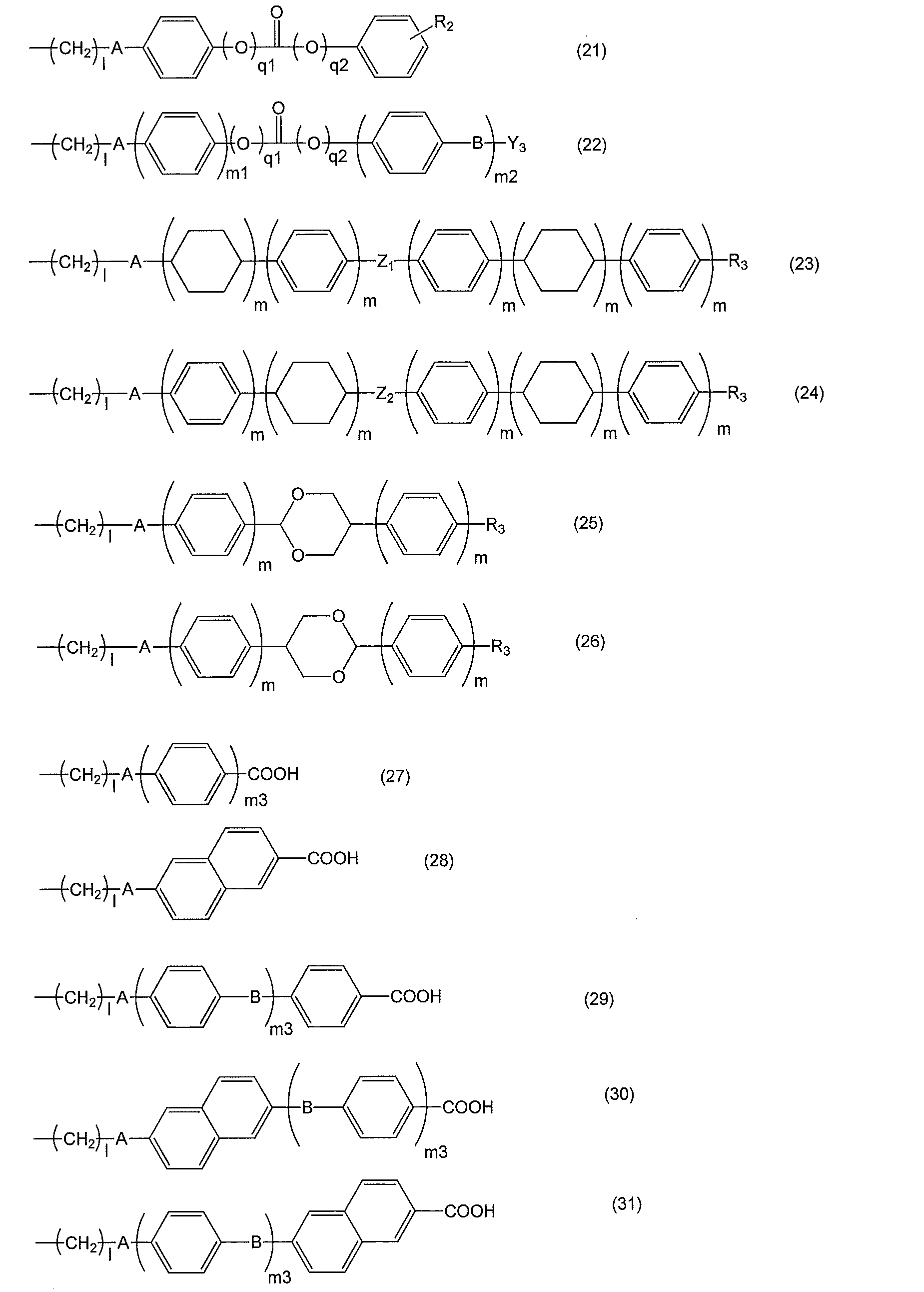
- [I] 請求項1~10のいずれか1項に記載の組成物を、横電界駆動用の導電膜を有する基板上に塗布して塗膜を形成する工程;
[II] [I]で得られた塗膜に偏光した紫外線を照射する工程;及び
[III] [II]で得られた塗膜を加熱する工程;
を有することによって配向制御能が付与された横電界駆動型液晶表示素子用液晶配向膜を得る、前記液晶配向膜を有する基板の製造方法。 - 請求項11記載の方法により製造された横電界駆動型液晶表示素子用液晶配向膜を有する基板。
- 請求項12記載の基板を有する横電界駆動型液晶表示素子。
- 請求項12記載の基板(第1の基板)を準備する工程;
[I’] 第2の基板上に 請求項1~10のいずれか1項に記載の組成物を、塗布して塗膜を形成する工程;
[II’] [I’]で得られた塗膜に偏光した紫外線を照射する工程;及び
[III’] [II’]で得られた塗膜を加熱する工程;
を有することによって配向制御能が付与された液晶配向膜を得る、前記液晶配向膜を有する第2の基板を得る工程;及び
[IV] 液晶を介して前記第1及び第2の基板の液晶配向膜が相対するように、前記第1及び第2の基板を対向配置して液晶表示素子を得る工程;
を有することにより、横電界駆動型液晶表示素子を得る、該液晶表示素子の製造方法。 - 請求項14記載の方法により製造された横電界駆動型液晶表示素子。
Priority Applications (3)
| Application Number | Priority Date | Filing Date | Title |
|---|---|---|---|
| CN201480058026.XA CN105658730B (zh) | 2013-08-22 | 2014-08-22 | 具有横向电场驱动型液晶表示元件用液晶取向膜的基板的制造方法 |
| JP2015532904A JP6571524B2 (ja) | 2013-08-22 | 2014-08-22 | 横電界駆動型液晶表示素子用液晶配向膜を有する基板の製造方法 |
| KR1020167007359A KR102204768B1 (ko) | 2013-08-22 | 2014-08-22 | 횡전계 구동형 액정 표시 소자용 액정 배향막을 갖는 기판의 제조 방법 |
Applications Claiming Priority (2)
| Application Number | Priority Date | Filing Date | Title |
|---|---|---|---|
| JP2013172467 | 2013-08-22 | ||
| JP2013-172467 | 2013-08-22 |
Publications (1)
| Publication Number | Publication Date |
|---|---|
| WO2015025937A1 true WO2015025937A1 (ja) | 2015-02-26 |
Family
ID=52483708
Family Applications (1)
| Application Number | Title | Priority Date | Filing Date |
|---|---|---|---|
| PCT/JP2014/071952 Ceased WO2015025937A1 (ja) | 2013-08-22 | 2014-08-22 | 横電界駆動型液晶表示素子用液晶配向膜を有する基板の製造方法 |
Country Status (5)
| Country | Link |
|---|---|
| JP (1) | JP6571524B2 (ja) |
| KR (1) | KR102204768B1 (ja) |
| CN (1) | CN105658730B (ja) |
| TW (1) | TWI644931B (ja) |
| WO (1) | WO2015025937A1 (ja) |
Cited By (4)
| Publication number | Priority date | Publication date | Assignee | Title |
|---|---|---|---|---|
| WO2015156314A1 (ja) * | 2014-04-09 | 2015-10-15 | 日産化学工業株式会社 | 液晶配向剤、液晶配向膜及び液晶表示素子 |
| WO2017170943A1 (ja) * | 2016-03-31 | 2017-10-05 | 日産化学工業株式会社 | 液晶配向剤、液晶配向膜、及び液晶表示素子 |
| WO2017170945A1 (ja) * | 2016-03-31 | 2017-10-05 | 日産化学工業株式会社 | 液晶配向剤、液晶配向膜、及び液晶表示素子 |
| JP2022027233A (ja) * | 2020-07-31 | 2022-02-10 | Jsr株式会社 | 液晶配向剤、液晶配向膜及び液晶素子 |
Citations (6)
| Publication number | Priority date | Publication date | Assignee | Title |
|---|---|---|---|---|
| JP2007304215A (ja) * | 2006-05-09 | 2007-11-22 | Hayashi Telempu Co Ltd | 光配向材および光学素子、液晶配向膜の製造方法 |
| JP2008276149A (ja) * | 2007-04-27 | 2008-11-13 | Hayashi Telempu Co Ltd | 高分子フィルム、分子配向素子の作製方法、および液晶配向膜 |
| JP2013033248A (ja) * | 2011-07-07 | 2013-02-14 | Sumitomo Chemical Co Ltd | 光反応性液晶配向剤、液晶配向素子及びその製造方法 |
| JP2013033249A (ja) * | 2011-07-07 | 2013-02-14 | Sumitomo Chemical Co Ltd | 偏光素子、円偏光板及びそれらの製造方法 |
| WO2013038932A1 (ja) * | 2011-09-12 | 2013-03-21 | 株式会社林技術研究所 | 光学位相差素子およびその製造方法 |
| WO2013081066A1 (ja) * | 2011-11-29 | 2013-06-06 | 日産化学工業株式会社 | 液晶配向膜の製造方法、液晶配向膜及び液晶表示素子 |
Family Cites Families (3)
| Publication number | Priority date | Publication date | Assignee | Title |
|---|---|---|---|---|
| JPH0237324A (ja) | 1988-07-27 | 1990-02-07 | Sanyo Electric Co Ltd | ポリイミド配向膜の製造方法 |
| JP3893659B2 (ja) | 1996-03-05 | 2007-03-14 | 日産化学工業株式会社 | 液晶配向処理方法 |
| KR101089211B1 (ko) * | 2010-12-02 | 2011-12-02 | 엘티씨 (주) | 1차 알칸올 아민을 포함하는 lcd 제조용 포토레지스트 박리액 조성물 |
-
2014
- 2014-08-22 CN CN201480058026.XA patent/CN105658730B/zh active Active
- 2014-08-22 TW TW103128963A patent/TWI644931B/zh active
- 2014-08-22 JP JP2015532904A patent/JP6571524B2/ja active Active
- 2014-08-22 WO PCT/JP2014/071952 patent/WO2015025937A1/ja not_active Ceased
- 2014-08-22 KR KR1020167007359A patent/KR102204768B1/ko active Active
Patent Citations (6)
| Publication number | Priority date | Publication date | Assignee | Title |
|---|---|---|---|---|
| JP2007304215A (ja) * | 2006-05-09 | 2007-11-22 | Hayashi Telempu Co Ltd | 光配向材および光学素子、液晶配向膜の製造方法 |
| JP2008276149A (ja) * | 2007-04-27 | 2008-11-13 | Hayashi Telempu Co Ltd | 高分子フィルム、分子配向素子の作製方法、および液晶配向膜 |
| JP2013033248A (ja) * | 2011-07-07 | 2013-02-14 | Sumitomo Chemical Co Ltd | 光反応性液晶配向剤、液晶配向素子及びその製造方法 |
| JP2013033249A (ja) * | 2011-07-07 | 2013-02-14 | Sumitomo Chemical Co Ltd | 偏光素子、円偏光板及びそれらの製造方法 |
| WO2013038932A1 (ja) * | 2011-09-12 | 2013-03-21 | 株式会社林技術研究所 | 光学位相差素子およびその製造方法 |
| WO2013081066A1 (ja) * | 2011-11-29 | 2013-06-06 | 日産化学工業株式会社 | 液晶配向膜の製造方法、液晶配向膜及び液晶表示素子 |
Cited By (14)
| Publication number | Priority date | Publication date | Assignee | Title |
|---|---|---|---|---|
| WO2015156314A1 (ja) * | 2014-04-09 | 2015-10-15 | 日産化学工業株式会社 | 液晶配向剤、液晶配向膜及び液晶表示素子 |
| CN109196412A (zh) * | 2016-03-31 | 2019-01-11 | 日产化学株式会社 | 液晶取向剂、液晶取向膜、以及液晶表示元件 |
| WO2017170945A1 (ja) * | 2016-03-31 | 2017-10-05 | 日産化学工業株式会社 | 液晶配向剤、液晶配向膜、及び液晶表示素子 |
| KR20180124127A (ko) * | 2016-03-31 | 2018-11-20 | 닛산 가가쿠 가부시키가이샤 | 액정 배향제, 액정 배향막, 및 액정 표시 소자 |
| KR20180129874A (ko) * | 2016-03-31 | 2018-12-05 | 닛산 가가쿠 가부시키가이샤 | 액정 배향제, 액정 배향막, 및 액정 표시 소자 |
| CN109196411A (zh) * | 2016-03-31 | 2019-01-11 | 日产化学株式会社 | 液晶取向剂、液晶取向膜、以及液晶表示元件 |
| WO2017170943A1 (ja) * | 2016-03-31 | 2017-10-05 | 日産化学工業株式会社 | 液晶配向剤、液晶配向膜、及び液晶表示素子 |
| JPWO2017170945A1 (ja) * | 2016-03-31 | 2019-02-21 | 日産化学株式会社 | 液晶配向剤、液晶配向膜、及び液晶表示素子 |
| JPWO2017170943A1 (ja) * | 2016-03-31 | 2019-03-07 | 日産化学株式会社 | 液晶配向剤、液晶配向膜、及び液晶表示素子 |
| KR102292494B1 (ko) | 2016-03-31 | 2021-08-20 | 닛산 가가쿠 가부시키가이샤 | 액정 배향제, 액정 배향막, 및 액정 표시 소자 |
| JP7052721B2 (ja) | 2016-03-31 | 2022-04-12 | 日産化学株式会社 | 液晶配向剤、液晶配向膜、及び液晶表示素子 |
| KR102399376B1 (ko) * | 2016-03-31 | 2022-05-17 | 닛산 가가쿠 가부시키가이샤 | 액정 배향제, 액정 배향막, 및 액정 표시 소자 |
| JP2022027233A (ja) * | 2020-07-31 | 2022-02-10 | Jsr株式会社 | 液晶配向剤、液晶配向膜及び液晶素子 |
| JP7512749B2 (ja) | 2020-07-31 | 2024-07-09 | Jsr株式会社 | 液晶配向剤、液晶配向膜及び液晶素子 |
Also Published As
| Publication number | Publication date |
|---|---|
| CN105658730B (zh) | 2017-11-14 |
| CN105658730A (zh) | 2016-06-08 |
| JP6571524B2 (ja) | 2019-09-04 |
| TW201522384A (zh) | 2015-06-16 |
| KR102204768B1 (ko) | 2021-01-18 |
| TWI644931B (zh) | 2018-12-21 |
| KR20160048848A (ko) | 2016-05-04 |
| JPWO2015025937A1 (ja) | 2017-03-02 |
Similar Documents
| Publication | Publication Date | Title |
|---|---|---|
| JP7140336B2 (ja) | 液晶配向剤、液晶配向膜及び液晶表示素子 | |
| JP2015007702A (ja) | 横電界駆動型液晶表示素子用液晶配向膜を有する基板の製造方法 | |
| JP2014206715A (ja) | 横電界駆動型液晶表示素子用液晶配向膜を有する基板の製造方法 | |
| WO2017199986A1 (ja) | 液晶配向剤、液晶配向膜及び液晶表示素子 | |
| WO2015012341A1 (ja) | 重合体、重合体組成物および横電界駆動型液晶表示素子用液晶配向膜 | |
| JP6723523B2 (ja) | 重合体組成物、液晶配向剤、液晶配向膜、該液晶配向膜を有する基板及び該液晶配向膜を有する液晶表示素子 | |
| WO2014196590A1 (ja) | 横電界駆動型液晶表示素子用液晶配向膜を有する基板の製造方法 | |
| WO2014185411A1 (ja) | 横電界駆動型液晶表示素子用液晶配向膜を有する基板の製造方法 | |
| JP6571524B2 (ja) | 横電界駆動型液晶表示素子用液晶配向膜を有する基板の製造方法 | |
| WO2016113931A1 (ja) | 非光反応性の水素結合性高分子液晶を用いた液晶配向剤、及び液晶配向膜 | |
| CN107636081B (zh) | 使用了光反应性氢键性高分子液晶的液晶取向剂和液晶取向膜 | |
| JP6872315B2 (ja) | 重合体組成物および横電界駆動型液晶表示素子用液晶配向膜 | |
| WO2014196589A1 (ja) | 横電界駆動型液晶表示素子用液晶配向膜を有する基板の製造方法 | |
| JP6794257B2 (ja) | 液晶配向剤、液晶配向膜および液晶表示素子 | |
| WO2017069133A1 (ja) | 液晶配向剤、液晶配向膜および液晶表示素子 | |
| CN105431770B (zh) | 具有横向电场驱动型液晶表示元件用液晶取向膜的基板的制造方法 | |
| KR102254609B1 (ko) | 횡전계 구동형 액정 표시 소자용 액정 배향막을 갖는 기판의 제조 방법 | |
| JP2018109788A (ja) | 横電界駆動型液晶表示素子用液晶配向膜を有する基板の製造方法 |
Legal Events
| Date | Code | Title | Description |
|---|---|---|---|
| 121 | Ep: the epo has been informed by wipo that ep was designated in this application |
Ref document number: 14837886 Country of ref document: EP Kind code of ref document: A1 |
|
| ENP | Entry into the national phase |
Ref document number: 2015532904 Country of ref document: JP Kind code of ref document: A |
|
| NENP | Non-entry into the national phase |
Ref country code: DE |
|
| ENP | Entry into the national phase |
Ref document number: 20167007359 Country of ref document: KR Kind code of ref document: A |
|
| 122 | Ep: pct application non-entry in european phase |
Ref document number: 14837886 Country of ref document: EP Kind code of ref document: A1 |