WO2015025907A1 - 車両用空気調和装置 - Google Patents
車両用空気調和装置 Download PDFInfo
- Publication number
- WO2015025907A1 WO2015025907A1 PCT/JP2014/071835 JP2014071835W WO2015025907A1 WO 2015025907 A1 WO2015025907 A1 WO 2015025907A1 JP 2014071835 W JP2014071835 W JP 2014071835W WO 2015025907 A1 WO2015025907 A1 WO 2015025907A1
- Authority
- WO
- WIPO (PCT)
- Prior art keywords
- heating
- heat exchanger
- air
- refrigerant
- frost
- Prior art date
- Legal status (The legal status is an assumption and is not a legal conclusion. Google has not performed a legal analysis and makes no representation as to the accuracy of the status listed.)
- Ceased
Links
Images






Classifications
-
- B—PERFORMING OPERATIONS; TRANSPORTING
- B60—VEHICLES IN GENERAL
- B60H—ARRANGEMENTS OF HEATING, COOLING, VENTILATING OR OTHER AIR-TREATING DEVICES SPECIALLY ADAPTED FOR PASSENGER OR GOODS SPACES OF VEHICLES
- B60H1/00—Heating, cooling or ventilating devices
- B60H1/00642—Control systems or circuits; Control members or indication devices for heating, cooling or ventilating devices
- B60H1/00735—Control systems or circuits characterised by their input, i.e. by the detection, measurement or calculation of particular conditions, e.g. signal treatment, dynamic models
- B60H1/00785—Control systems or circuits characterised by their input, i.e. by the detection, measurement or calculation of particular conditions, e.g. signal treatment, dynamic models by the detection of humidity or frost
-
- B—PERFORMING OPERATIONS; TRANSPORTING
- B60—VEHICLES IN GENERAL
- B60H—ARRANGEMENTS OF HEATING, COOLING, VENTILATING OR OTHER AIR-TREATING DEVICES SPECIALLY ADAPTED FOR PASSENGER OR GOODS SPACES OF VEHICLES
- B60H1/00—Heating, cooling or ventilating devices
- B60H1/00357—Air-conditioning arrangements specially adapted for particular vehicles
- B60H1/00385—Air-conditioning arrangements specially adapted for particular vehicles for vehicles having an electrical drive, e.g. hybrid or fuel cell
-
- B—PERFORMING OPERATIONS; TRANSPORTING
- B60—VEHICLES IN GENERAL
- B60H—ARRANGEMENTS OF HEATING, COOLING, VENTILATING OR OTHER AIR-TREATING DEVICES SPECIALLY ADAPTED FOR PASSENGER OR GOODS SPACES OF VEHICLES
- B60H1/00—Heating, cooling or ventilating devices
- B60H1/00642—Control systems or circuits; Control members or indication devices for heating, cooling or ventilating devices
- B60H1/00814—Control systems or circuits characterised by their output, for controlling particular components of the heating, cooling or ventilating installation
- B60H1/00878—Control systems or circuits characterised by their output, for controlling particular components of the heating, cooling or ventilating installation the components being temperature regulating devices
- B60H1/00899—Controlling the flow of liquid in a heat pump system
- B60H1/00921—Controlling the flow of liquid in a heat pump system where the flow direction of the refrigerant does not change and there is an extra subcondenser, e.g. in an air duct
-
- B—PERFORMING OPERATIONS; TRANSPORTING
- B60—VEHICLES IN GENERAL
- B60H—ARRANGEMENTS OF HEATING, COOLING, VENTILATING OR OTHER AIR-TREATING DEVICES SPECIALLY ADAPTED FOR PASSENGER OR GOODS SPACES OF VEHICLES
- B60H1/00—Heating, cooling or ventilating devices
- B60H1/22—Heating, cooling or ventilating devices the heat source being other than the propulsion plant
-
- F—MECHANICAL ENGINEERING; LIGHTING; HEATING; WEAPONS; BLASTING
- F25—REFRIGERATION OR COOLING; COMBINED HEATING AND REFRIGERATION SYSTEMS; HEAT PUMP SYSTEMS; MANUFACTURE OR STORAGE OF ICE; LIQUEFACTION SOLIDIFICATION OF GASES
- F25B—REFRIGERATION MACHINES, PLANTS OR SYSTEMS; COMBINED HEATING AND REFRIGERATION SYSTEMS; HEAT PUMP SYSTEMS
- F25B49/00—Arrangement or mounting of control or safety devices
- F25B49/02—Arrangement or mounting of control or safety devices for compression type machines, plants or systems
-
- B—PERFORMING OPERATIONS; TRANSPORTING
- B60—VEHICLES IN GENERAL
- B60H—ARRANGEMENTS OF HEATING, COOLING, VENTILATING OR OTHER AIR-TREATING DEVICES SPECIALLY ADAPTED FOR PASSENGER OR GOODS SPACES OF VEHICLES
- B60H1/00—Heating, cooling or ventilating devices
- B60H1/00642—Control systems or circuits; Control members or indication devices for heating, cooling or ventilating devices
- B60H1/00814—Control systems or circuits characterised by their output, for controlling particular components of the heating, cooling or ventilating installation
- B60H1/00878—Control systems or circuits characterised by their output, for controlling particular components of the heating, cooling or ventilating installation the components being temperature regulating devices
- B60H2001/00961—Control systems or circuits characterised by their output, for controlling particular components of the heating, cooling or ventilating installation the components being temperature regulating devices comprising means for defrosting outside heat exchangers
-
- F—MECHANICAL ENGINEERING; LIGHTING; HEATING; WEAPONS; BLASTING
- F25—REFRIGERATION OR COOLING; COMBINED HEATING AND REFRIGERATION SYSTEMS; HEAT PUMP SYSTEMS; MANUFACTURE OR STORAGE OF ICE; LIQUEFACTION SOLIDIFICATION OF GASES
- F25B—REFRIGERATION MACHINES, PLANTS OR SYSTEMS; COMBINED HEATING AND REFRIGERATION SYSTEMS; HEAT PUMP SYSTEMS
- F25B2400/00—Component parts or details not otherwise provided for in this subclass
- F25B2400/04—Refrigeration circuit bypassing means
- F25B2400/0403—Refrigeration circuit bypassing means for condensers
-
- F—MECHANICAL ENGINEERING; LIGHTING; HEATING; WEAPONS; BLASTING
- F25—REFRIGERATION OR COOLING; COMBINED HEATING AND REFRIGERATION SYSTEMS; HEAT PUMP SYSTEMS; MANUFACTURE OR STORAGE OF ICE; LIQUEFACTION SOLIDIFICATION OF GASES
- F25B—REFRIGERATION MACHINES, PLANTS OR SYSTEMS; COMBINED HEATING AND REFRIGERATION SYSTEMS; HEAT PUMP SYSTEMS
- F25B2400/00—Component parts or details not otherwise provided for in this subclass
- F25B2400/04—Refrigeration circuit bypassing means
- F25B2400/0409—Refrigeration circuit bypassing means for evaporators
-
- F—MECHANICAL ENGINEERING; LIGHTING; HEATING; WEAPONS; BLASTING
- F25—REFRIGERATION OR COOLING; COMBINED HEATING AND REFRIGERATION SYSTEMS; HEAT PUMP SYSTEMS; MANUFACTURE OR STORAGE OF ICE; LIQUEFACTION SOLIDIFICATION OF GASES
- F25B—REFRIGERATION MACHINES, PLANTS OR SYSTEMS; COMBINED HEATING AND REFRIGERATION SYSTEMS; HEAT PUMP SYSTEMS
- F25B2400/00—Component parts or details not otherwise provided for in this subclass
- F25B2400/04—Refrigeration circuit bypassing means
- F25B2400/0411—Refrigeration circuit bypassing means for expansion valves or capillary tubes
-
- F—MECHANICAL ENGINEERING; LIGHTING; HEATING; WEAPONS; BLASTING
- F25—REFRIGERATION OR COOLING; COMBINED HEATING AND REFRIGERATION SYSTEMS; HEAT PUMP SYSTEMS; MANUFACTURE OR STORAGE OF ICE; LIQUEFACTION SOLIDIFICATION OF GASES
- F25B—REFRIGERATION MACHINES, PLANTS OR SYSTEMS; COMBINED HEATING AND REFRIGERATION SYSTEMS; HEAT PUMP SYSTEMS
- F25B40/00—Subcoolers, desuperheaters or superheaters
-
- F—MECHANICAL ENGINEERING; LIGHTING; HEATING; WEAPONS; BLASTING
- F25—REFRIGERATION OR COOLING; COMBINED HEATING AND REFRIGERATION SYSTEMS; HEAT PUMP SYSTEMS; MANUFACTURE OR STORAGE OF ICE; LIQUEFACTION SOLIDIFICATION OF GASES
- F25B—REFRIGERATION MACHINES, PLANTS OR SYSTEMS; COMBINED HEATING AND REFRIGERATION SYSTEMS; HEAT PUMP SYSTEMS
- F25B41/00—Fluid-circulation arrangements
- F25B41/30—Expansion means; Dispositions thereof
- F25B41/39—Dispositions with two or more expansion means arranged in series, i.e. multi-stage expansion, on a refrigerant line leading to the same evaporator
-
- F—MECHANICAL ENGINEERING; LIGHTING; HEATING; WEAPONS; BLASTING
- F25—REFRIGERATION OR COOLING; COMBINED HEATING AND REFRIGERATION SYSTEMS; HEAT PUMP SYSTEMS; MANUFACTURE OR STORAGE OF ICE; LIQUEFACTION SOLIDIFICATION OF GASES
- F25B—REFRIGERATION MACHINES, PLANTS OR SYSTEMS; COMBINED HEATING AND REFRIGERATION SYSTEMS; HEAT PUMP SYSTEMS
- F25B5/00—Compression machines, plants or systems, with several evaporator circuits, e.g. for varying refrigerating capacity
- F25B5/04—Compression machines, plants or systems, with several evaporator circuits, e.g. for varying refrigerating capacity arranged in series
-
- F—MECHANICAL ENGINEERING; LIGHTING; HEATING; WEAPONS; BLASTING
- F25—REFRIGERATION OR COOLING; COMBINED HEATING AND REFRIGERATION SYSTEMS; HEAT PUMP SYSTEMS; MANUFACTURE OR STORAGE OF ICE; LIQUEFACTION SOLIDIFICATION OF GASES
- F25B—REFRIGERATION MACHINES, PLANTS OR SYSTEMS; COMBINED HEATING AND REFRIGERATION SYSTEMS; HEAT PUMP SYSTEMS
- F25B6/00—Compression machines, plants or systems, with several condenser circuits
- F25B6/04—Compression machines, plants or systems, with several condenser circuits arranged in series
Definitions
- the present invention relates to a so-called heat pump type air conditioner that air-conditions the interior of a vehicle, and more particularly to an air conditioner for a hybrid vehicle and an electric vehicle that can be fed from an external power source.
- an air conditioner that can be applied to such a vehicle, a compressor that compresses and discharges the refrigerant, a radiator (condenser) that is provided on the vehicle interior side to dissipate the refrigerant, and the vehicle interior side
- a heat absorber evaporator
- an outdoor heat exchanger that is provided outside the passenger compartment to dissipate or absorb the refrigerant, and dissipates the refrigerant discharged from the compressor in the radiator
- a heating mode in which the heat dissipated in the radiator is absorbed in the outdoor heat exchanger, a dehumidification mode in which the refrigerant discharged from the compressor is dissipated in the radiator, and the refrigerant dissipated in the radiator is absorbed in the heat absorber
- compression A refrigerant that has been radiated in an outdoor heat exchanger and is switched and executed in each cooling mode in
- an electric vehicle and some hybrid vehicles are configured so that a battery can be charged (so-called plug-in) by connecting to an external power source (charger) installed at home or a power supply facility (power supply point). Has been. If the battery is charged by such a plug-in, it is possible to contribute to improvement of fuel consumption particularly in a hybrid vehicle.
- the outdoor heat exchanger functions as a refrigerant evaporator. Therefore, when the compressor is operated directly by an external power source during plug-in or via a battery and the heating mode is executed, moisture in the outside air may be frosted on the outdoor heat exchanger depending on the temperature / humidity conditions of the outside air. It becomes attached and grows.
- frost is formed on the outdoor heat exchanger in the heating mode, the frost becomes a heat insulating material, so the heat exchange performance with the outside air is significantly deteriorated and heat cannot be absorbed from the outside air, and the required heating capacity is obtained. It becomes impossible.
- the present invention has been made to solve the above-described conventional technical problems, and in a so-called heat pump type vehicle air conditioner, an outdoor heat exchanger for heating a vehicle interior in advance during plug-in.
- An object of the present invention is to realize comfortable vehicle interior heating during traveling and to extend the traveling distance by preventing or suppressing frost formation on the vehicle.
- the vehicle air conditioner of the present invention heats the compressor that compresses the refrigerant, the air flow passage through which the air supplied to the vehicle interior flows, and the air that dissipates the refrigerant and is supplied from the air flow passage to the vehicle interior.
- a heat sink a heat absorber for cooling the air supplied to the vehicle interior from the air flow passage by absorbing the refrigerant, an outdoor heat exchanger provided outside the vehicle cabin for radiating or absorbing heat, and control means
- a heating mode in which at least the refrigerant discharged from the compressor is radiated by the radiator by the control means, and the radiated refrigerant is decompressed and then absorbed by the outdoor heat exchanger.
- an auxiliary heating means for heating the air supplied to the vehicle interior from the air flow passage, and the control means has a frost estimation means for estimating frost formation on the outdoor heat exchanger, and is compressed from an external power source. Or the compressor When the heating mode is executed in a state where power is supplied to a battery that supplies power for driving, when frost formation on the outdoor heat exchanger is predicted based on the estimation of the frost estimation means, the auxiliary heating means Heating is performed.
- the air conditioning apparatus for a vehicle according to claim 2 is characterized in that, in the above invention, the control means performs heating by a radiator when the heating capacity by the auxiliary heating means is insufficient with respect to the required heating capacity Qtgt. .
- control means compares the required heating capacity Qtgt with the maximum heating capacity that can be generated by the auxiliary heating means, and this maximum heating capacity is obtained from the required heating capacity Qtgt. The shortage is complemented by heating the radiator.
- the control means controls the compressor so that the refrigerant evaporation temperature in the outdoor heat exchanger is lower than the outside air temperature, and the difference between them is within a predetermined value. It is characterized by controlling.
- an air conditioning apparatus for a vehicle according to each of the first and second aspects of the present invention, wherein when the control means is predicted not to form frost on the outdoor heat exchanger based on the estimation of the frost state estimation means, heating by the auxiliary heating means is performed. Heating by a radiator is performed without performing the above.
- the frost estimation means is a non-frosting that is a target value of the maximum heating capacity that can be generated by the radiator within a range in which the outdoor heat exchanger does not frost.
- the maximum heating capacity predicted value TGQhpNfst is calculated, and when the non-frosting maximum heating capacity predicted value TGQhpNfst is smaller than the required heating capacity Qtgt or a value close thereto, it is predicted that the outdoor heat exchanger will be frosted. .
- the frost estimation means is based on the outside air temperature, or the time, solar radiation, rainfall, position, and weather conditions are added to the frost-free maximum heating capacity prediction.
- a value TGQhpNfst is calculated.
- the frost estimation means is a non-adhering temperature that is the refrigerant evaporation temperature of the outdoor heat exchanger when the required heating capacity Qtgt is achieved.
- the refrigeration required refrigerant evaporation temperature TXObaseQtgt is calculated, and when the non-frosting required refrigerant evaporation temperature TXObaseQtgt is lower than the frost point Tfrost or a temperature close thereto, it is predicted that the outdoor heat exchanger will be frosted. .
- the vehicle air conditioner according to the ninth aspect of the invention is characterized in that, in the above invention, the frost estimation means calculates the required refrigerant evaporation temperature TXObaseQtgt at the time of no frost formation based on the outside air temperature and the required heating capacity Qtgt.
- a vehicle air conditioner includes a heat medium-air heat exchanger for heating air supplied from the air flow passage to the vehicle interior, an electric heater, and a circulation means.
- the auxiliary heating means is constituted by a heat medium circulation circuit for circulating the heat medium heated by the electric heater to the heat medium-air heat exchanger by the circulation means.
- a compressor for compressing a refrigerant, an air flow passage through which air to be supplied to the vehicle interior flows, and a radiator for heating the air to be radiated from the refrigerant and supplied to the vehicle interior from the air flow passage.
- a heat absorber for cooling the refrigerant to absorb heat and supplying air from the air flow passage to the vehicle interior
- an outdoor heat exchanger that is provided outside the vehicle and radiates or absorbs the refrigerant
- a control means In the vehicle air conditioner that executes a heating mode in which at least the refrigerant discharged from the compressor is radiated by the radiator by this control means, and the radiated refrigerant is depressurized and then absorbed by the outdoor heat exchanger.
- Auxiliary heating means for heating the air supplied from the air flow passage to the vehicle interior is provided, and the control means has frost estimation means for estimating frost formation on the outdoor heat exchanger, and the compressor from the external power source, Or the compressor
- the auxiliary heating means Since the heating is executed, when the vehicle interior is preheated (pre-air conditioning) during so-called plug-in, the vehicle interior heating is performed by auxiliary heating means while preventing or suppressing frost formation on the outdoor heat exchanger. It is possible to reduce the load during the subsequent running.
- the control means as in the invention of claim 2 performs so-called pre-air conditioning in the cold season or at night by performing heating with a radiator. (Heating) can be realized without hindrance. Further, when the heating capacity by the auxiliary heating means satisfies the required heating capacity Qtgt, the compressor is not operated, so that frost formation on the outdoor heat exchanger is reliably prevented.
- control means compares the required heating capacity Qtgt with the maximum heating capacity that can be generated by the auxiliary heating means, and determines that the maximum heating capacity is less than the required heating capacity Qtgt.
- control means controls the compressor so that the refrigerant evaporation temperature in the outdoor heat exchanger is lower than the outside air temperature, and the difference between them is within a predetermined value.
- the frost formation on the heat exchanger is effectively prevented or suppressed.
- the control means is predicted not to form frost on the outdoor heat exchanger based on the estimation of the frost state estimation means as in the invention of claim 5, the heat is not generated by the auxiliary heating means, and the radiator is used. By performing the heating, it is possible to reduce power consumption for heating during so-called plug-in without any trouble.
- the frost estimation means calculates a frost-free maximum heating capacity prediction value TGQhpNfst that is a target value of the maximum heating capacity that can be generated by the radiator within a range where the outdoor heat exchanger does not frost.
- TGQhpNfst When the predicted maximum frost-free heating capacity value TGQhpNfst is smaller than the required heating capacity Qtgt or a value close to the required heating capacity Qtgt, frost is generated in the outdoor heat exchanger by predicting frost formation on the outdoor heat exchanger. Even when the point cannot be detected, frost formation on the outdoor heat exchanger during plug-in can be effectively prevented or suppressed.
- the frosting estimation means calculates the non-frosting maximum heating capacity predicted value TGQhpNfst based on the outside air temperature or adding the time, solar radiation, rainfall, position, and weather conditions to it as in the invention of claim 7.
- the frost-free maximum heating capacity predicted value TGQhpNfst that does not frost on the outdoor heat exchanger is accurately estimated, that is, as a result, the frost point is accurately estimated and frost formation on the outdoor heat exchanger during plug-in is performed. It can be prevented or suppressed more effectively.
- the frost formation estimation means calculates the required refrigerant evaporation temperature TXObaseQtgt at the time of non-frost, which is the refrigerant evaporation temperature of the outdoor heat exchanger when the required heating capacity Qtgt is realized, as in the invention of claim 8.
- the frost required refrigerant evaporation temperature TXObaseQtgt is lower than the frost point Tfrost or a temperature close thereto, it is predicted that the outdoor heat exchanger will be frosted, so that the frost point is generated in the outdoor heat exchanger. It is possible to effectively prevent or suppress frost formation on the outdoor heat exchanger.
- the frosting estimation means calculates the non-frosting required refrigerant evaporation temperature TXObaseQtgt based on the outside air temperature and the required heating capacity Qtgt. To accurately estimate the required refrigerant evaporation temperature TXObaseQtgt for non-frosting that achieves the required heating capacity Qtgt, and to more effectively prevent or suppress frosting on the outdoor heat exchanger during plug-in Become.
- the auxiliary heating means described above as in the invention of claim 10 comprises a heat medium-air heat exchanger for heating air supplied from the air flow passage into the vehicle compartment, an electric heater, and a circulation means.
- a heat medium-air heat exchanger for heating air supplied from the air flow passage into the vehicle compartment
- an electric heater for heating air supplied from the air flow passage into the vehicle compartment
- a circulation means for configuring the heat medium heated by the electric heater from the heat medium circulation circuit that circulates the heat medium to the heat medium-air heat exchanger by the circulation means, it becomes possible to realize an electrically safer vehicle interior heating. Is.
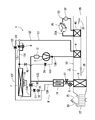
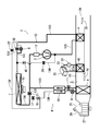
- FIG. 1 shows a configuration diagram of a vehicle air conditioner 1 according to an embodiment of the present invention.
- a vehicle according to an embodiment to which the present invention is applied is an electric vehicle (EV) in which an engine (internal combustion engine) is not mounted, and an electric motor for traveling with electric power charged (plugged in) from an external power source to a battery.
- the vehicle is driven and driven (none of which are shown), and the vehicle air conditioner 1 of the present invention is also driven by the power of the battery. That is, the vehicle air conditioner 1 of the embodiment performs heating by a heat pump operation using a refrigerant circuit in an electric vehicle that cannot be heated by engine waste heat, and further operates in each operation mode such as dehumidifying heating, cooling dehumidification, and cooling. Is selectively executed.
- the present invention is effective not only for electric vehicles as vehicles but also for so-called hybrid vehicles that use an engine and an electric motor for traveling and that can be plugged in to charge a battery from an external power source. .
- the vehicle air conditioner 1 performs air conditioning (heating, cooling, dehumidification, and ventilation) in a vehicle interior of an electric vehicle, and includes an electric compressor 2 that compresses refrigerant and vehicle interior air. Is provided in the air flow passage 3 of the HVAC unit 10 through which air is circulated, and the high-temperature and high-pressure refrigerant discharged from the compressor 2 flows in through the refrigerant pipe 13G, and dissipates the refrigerant into the vehicle compartment.
- an outdoor expansion valve 6 composed of an electric valve that decompresses and expands the refrigerant during heating, and an outdoor heat exchange that functions as a radiator during cooling and performs heat exchange between the refrigerant and the outside air so as to function as an evaporator during heating.
- a heat exchanger 9 an indoor expansion valve 8 including an electric valve for decompressing and expanding the refrigerant, a heat absorber 9 provided in the air flow passage 3 to absorb heat from the outside of the vehicle interior during cooling and dehumidification, and a heat absorber 9.
- Steam to adjust evaporation capacity A capacity control valve 11, the accumulator 12 and the like are sequentially connected by a refrigerant pipe 13, the refrigerant circuit R is formed.
- the outdoor heat exchanger 7 is provided with an outdoor blower 15.
- the outdoor blower 15 exchanges heat between the outside air and the refrigerant by forcibly passing outside air through the outdoor heat exchanger 7, and thereby stops the vehicle (that is, the vehicle speed VSP is 0 km / h).
- the outdoor heat exchanger 7 is configured to ventilate the outside air.
- the outdoor heat exchanger 7 has a receiver dryer section 14 and a supercooling section 16 in order on the downstream side of the refrigerant, and the refrigerant pipe 13A exiting from the outdoor heat exchanger 7 is an electromagnetic valve (open / close valve) 17 that is opened during cooling.
- the outlet of the supercooling unit 16 is connected to the indoor expansion valve 8 via a check valve 18.
- the receiver dryer section 14 and the supercooling section 16 structurally constitute a part of the outdoor heat exchanger 7, and the check valve 18 has a forward direction on the indoor expansion valve 8 side.
- the refrigerant pipe 13B between the check valve 18 and the indoor expansion valve 8 is provided in a heat exchange relationship with the refrigerant pipe 13C exiting the evaporation capacity control valve 11 located on the outlet side of the heat absorber 9, and internal heat is generated by both.
- the exchanger 19 is configured.
- the refrigerant flowing into the indoor expansion valve 8 through the refrigerant pipe 13B is cooled (supercooled) by the low-temperature refrigerant that has exited the heat absorber 9 and passed through the evaporation capacity control valve 11.
- the refrigerant pipe 13A exiting from the outdoor heat exchanger 7 is branched, and this branched refrigerant pipe 13D is downstream of the internal heat exchanger 19 via an electromagnetic valve (open / close valve) 21 that is opened during heating.
- the refrigerant pipe 13C is connected in communication.
- the refrigerant pipe 13E on the outlet side of the radiator 4 is branched in front of the outdoor expansion valve 6, and this branched refrigerant pipe 13F is a check valve via an electromagnetic valve (open / close valve) 22 that is opened during dehumidification. 18 is connected to the refrigerant pipe 13B on the downstream side.
- a bypass pipe 13J is connected to the outdoor expansion valve 6 in parallel.
- the bypass pipe 13J is opened in a cooling mode, and is an electromagnetic valve (open / close valve) for bypassing the outdoor expansion valve 6 and flowing refrigerant. ) 20 is interposed.
- the refrigerant pipe 13G on the discharge side of the compressor 2 branches, and the branched refrigerant pipe 13H is opened in the defrosting mode (defrosting operation) of the outdoor heat exchanger 7, and the high-temperature refrigerant discharged from the compressor 2 is discharged.
- the refrigerant pipe 13I is connected in communication.
- This electromagnetic valve 24 constitutes a defrosting means.
- the check valve 45 has a forward direction in the direction of the refrigerant pipe 13I.
- the air flow passage 3 on the air upstream side of the heat absorber 9 is formed with each of an outside air inlet and an inside air inlet (represented by the inlet 25 in FIG. 1). 25 is provided with a suction switching damper 26 for switching the air introduced into the air flow passage 3 between the inside air (inside air circulation mode) which is air inside the passenger compartment and the outside air (outside air introduction mode) which is outside the passenger compartment. Yes. Furthermore, an indoor blower (blower fan) 27 for supplying the introduced inside air or outside air to the air flow passage 3 is provided on the air downstream side of the suction switching damper 26.
- an indoor blower (blower fan) 27 for supplying the introduced inside air or outside air to the air flow passage 3 is provided on the air downstream side of the suction switching damper 26.
- reference numeral 23 denotes a heat medium circulation circuit as auxiliary heating means provided in the vehicle air conditioner 1 of the embodiment.
- the heat medium circulation circuit 23 has a circulation pump 30 constituting a circulation means, a heat medium heating electric heater (indicated by an auxiliary HTR in the drawing) 35, and the air flow of the radiator 4 with respect to the air flow in the air flow passage 3.
- a heat medium-air heat exchanger 40 provided in the air flow passage 3 on the downstream side is provided, and these are sequentially connected in an annular shape by a heat medium pipe 23A.
- the heat medium circulated in the heat medium circuit 23 for example, water, a refrigerant such as HFO-1234yf, a coolant, or the like is employed.
- the circulation pump 30 When the circulation pump 30 is operated and the heat medium heating electric heater 35 is energized to generate heat, the heat medium heated by the heat medium heating electric heater 35 is circulated to the heat medium-air heat exchanger 40.
- the heat medium-air heat exchanger 40 of the heat medium circulation circuit 23 becomes a so-called heater core, and complements the heating of the passenger compartment.
- an air mix damper 28 is provided in the air flow passage 3 on the air upstream side of the radiator 4 to adjust the degree of flow of inside air and outside air to the radiator 4. Further, in the air flow passage 3 on the downstream side of the radiator 4, foot, vent, and differential air outlets (represented by the air outlet 29 in FIG. 1) are formed. Is provided with a blower outlet switching damper 31 for switching and controlling the blowing of air from each of the blowout ports.
- 32 is a controller (ECU) as a control means and a frost estimation means comprised of a microcomputer
- an input of the controller 32 is an outside air temperature sensor 33 for detecting the outside air temperature of the vehicle
- An outside air humidity sensor 34 that detects the outside air humidity of the vehicle
- an HVAC suction temperature sensor 36 that detects the temperature of air sucked into the air flow passage 3 from the suction port 25, and an inside air that detects the temperature of the air (inside air) in the vehicle interior
- the discharge temperature sensor 41 for detecting the discharge pressure
- the discharge pressure sensor 42 for detecting the discharge refrigerant pressure of the compressor 2
- the discharge for detecting the discharge refrigerant temperature of the compressor 2 Degree sensor 43
- a suction pressure sensor 44 that detects the suction ref
- the temperature of the air passing through the heat absorber or the temperature of the heat absorber 9 itself is detected, and the refrigerant pressure of the heat absorber 9 (in the heat absorber 9 or just after leaving the heat absorber 9 is the pressure of the refrigerant).
- Air conditioning for setting temperature and operation mode switching C
- the operation unit 53 and the outdoor heat exchanger temperature sensor 54 for detecting the temperature of the outdoor heat exchanger 7 (the temperature of the refrigerant immediately after coming out of the outdoor heat exchanger 7 or the temperature of the outdoor heat exchanger 7 itself).
- each output of the outdoor heat exchanger pressure sensor 56 for detecting the refrigerant pressure of the outdoor heat exchanger 7 (the pressure of the refrigerant in the outdoor heat exchanger 7 or just after the refrigerant is discharged from the outdoor heat exchanger 7). ing.
- the input of the controller 32 further includes the temperature of the heating medium heating electric heater 35 of the heating medium circulation circuit 23 (the temperature of the heating medium immediately after being heated by the heating medium heating electric heater 35 or the heating medium heating electric heater 35.
- the temperature of the electric heater through the heat medium heating air heater 40 (the temperature of the air passing through the heat medium-air heat exchanger 40, Alternatively, the outputs of the heat medium-air heat exchanger temperature sensor 55 for detecting the temperature of the heat medium-air heat exchanger 40 itself are also connected.
- the output of the controller 32 includes the compressor 2, the outdoor fan 15, the indoor fan (blower fan) 27, the suction switching damper 26, the air mix damper 28, the suction port switching damper 31, and the outdoor expansion.
- the valve 6, the indoor expansion valve 8, the electromagnetic valves 22, 17, 21, 20, 24, the circulation pump 30, the heat medium heating electric heater 35, and the evaporation capacity control valve 11 are connected. And the controller 32 controls these based on the output of each sensor, and the setting input in the air-conditioning operation part 53.
- the controller 32 is roughly divided into a heating mode, a dehumidifying heating mode, an internal cycle mode, a dehumidifying cooling mode, and a cooling mode, and executes them.
- a heating mode a dehumidifying heating mode
- an internal cycle mode a dehumidifying cooling mode
- a cooling mode a cooling mode
- the controller 32 opens the solenoid valve 21, and the solenoid valve 17, the solenoid valve 22, and the solenoid valve. 20 and the solenoid valve 24 are closed.
- the compressor 2 and the blowers 15 and 27 are operated, and the air mix damper 28 is in a state where the air blown out from the indoor blower 27 is passed through the radiator 4 and the heat medium-air heat exchanger 40. .
- the high-temperature and high-pressure gas refrigerant discharged from the compressor 2 flows into the radiator 4.
- the air in the air flow passage 3 is passed through the radiator 4, the air in the air flow passage 3 is heated by the high-temperature refrigerant in the radiator 4, while the refrigerant in the radiator 4 heats the air. Deprived, cooled, and condensed into liquid.
- the refrigerant liquefied in the radiator 4 exits the radiator 4 and then reaches the outdoor expansion valve 6 through the refrigerant pipe 13E.
- the operation and action of the heat medium circulation circuit 23 will be described later.
- the refrigerant flowing into the outdoor expansion valve 6 is decompressed there and then flows into the outdoor heat exchanger 7.
- the refrigerant flowing into the outdoor heat exchanger 7 evaporates, and pumps up heat from the outside air that is ventilated by traveling or by the outdoor blower 15. That is, the refrigerant circuit R becomes a heat pump (indicated by HP in the drawing), and the outdoor heat exchanger 7 functions as a refrigerant evaporator.
- the low-temperature refrigerant exiting the outdoor heat exchanger 7 enters the accumulator 12 from the refrigerant pipe 13C through the refrigerant pipe 13D and the electromagnetic valve 21, and after being gas-liquid separated there, the gas refrigerant is sucked into the compressor 2. repeat. Since the air heated by the radiator 4 is blown out from the outlet 29 through the heat medium-air heat exchanger 40, the vehicle interior is thereby heated.
- the controller 32 controls the number of revolutions of the compressor 2 based on the high pressure of the refrigerant circuit R detected by the discharge pressure sensor 42 or the radiator pressure sensor 47, and the temperature of the radiator 4 detected by the radiator temperature sensor 46.
- the valve opening degree of the outdoor expansion valve 6 is controlled based on the refrigerant pressure of the radiator 4 detected by the radiator pressure sensor 47, and the degree of supercooling of the refrigerant at the outlet of the radiator 4 is controlled.
- the controller 32 opens the electromagnetic valve 22 in the heating mode.
- a part of the condensed refrigerant flowing through the refrigerant pipe 13E via the radiator 4 is diverted to reach the indoor expansion valve 8 via the electromagnetic valve 22 and the refrigerant pipes 13F and 13B via the internal heat exchanger 19.
- the refrigerant After the refrigerant is depressurized by the indoor expansion valve 8, it flows into the heat absorber 9 and evaporates. Since the moisture in the air blown out from the indoor blower 27 by the heat absorption action at this time condenses and adheres to the heat absorber 9, the air is cooled and dehumidified.
- the refrigerant evaporated in the heat absorber 9 merges with the refrigerant from the refrigerant pipe 13D in the refrigerant pipe 13C through the evaporation capacity control valve 11 and the internal heat exchanger 19, and then repeats circulation sucked into the compressor 2 through the accumulator 12. . Since the air dehumidified by the heat absorber 9 is reheated in the process of passing through the radiator 4, dehumidifying heating in the passenger compartment is thereby performed.
- the controller 32 controls the number of revolutions of the compressor 2 based on the high pressure of the refrigerant circuit R detected by the discharge pressure sensor 42 or the radiator pressure sensor 47 and adjusts the temperature of the heat absorber 9 detected by the heat absorber temperature sensor 48. Based on this, the valve opening degree of the outdoor expansion valve 6 is controlled.
- coolant piping 13F reaches the indoor expansion valve 8 through the internal heat exchanger 19 from the refrigerant
- the refrigerant evaporated in the heat absorber 9 flows through the refrigerant pipe 13C through the evaporation capacity control valve 11 and the internal heat exchanger 19, and repeats circulation sucked into the compressor 2 through the accumulator 12. Since the air dehumidified by the heat absorber 9 is reheated in the process of passing through the radiator 4, dehumidification heating is performed in the vehicle interior, but in this internal cycle mode, the air flow path on the indoor side 3, the refrigerant is circulated between the radiator 4 (heat radiation) and the heat absorber 9 (heat absorption), so that heat from the outside air is not pumped up, and the heating capacity for the power consumption of the compressor 2 Is demonstrated. Since the entire amount of the refrigerant flows through the heat absorber 9 that exhibits the dehumidifying action, the dehumidifying capacity is higher than that in the dehumidifying and heating mode, but the heating capacity is lowered.
- the controller 32 controls the rotation speed of the compressor 2 based on the temperature of the heat absorber 9 or the high pressure of the refrigerant circuit R described above. At this time, the controller 32 controls the compressor 2 by selecting the lower one of the compressor target rotational speeds obtained from either calculation, depending on the temperature of the heat absorber 9 or the high pressure.
- the controller 32 opens the electromagnetic valve 17 and closes the electromagnetic valve 21, the electromagnetic valve 22, the electromagnetic valve 20, and the electromagnetic valve 24. Then, the compressor 2 and the blowers 15 and 27 are operated, and the air mix damper 28 is in a state where the air blown out from the indoor blower 27 is passed through the radiator 4 and the heat medium-air heat exchanger 40. . Thereby, the high-temperature and high-pressure gas refrigerant discharged from the compressor 2 flows into the radiator 4.
- the air in the air flow passage 3 is passed through the radiator 4, the air in the air flow passage 3 is heated by the high-temperature refrigerant in the radiator 4, while the refrigerant in the radiator 4 heats the air. It is deprived and cooled, and condensates.
- the refrigerant that has exited the radiator 4 reaches the outdoor expansion valve 6 through the refrigerant pipe 13E, and flows into the outdoor heat exchanger 7 through the outdoor expansion valve 6 that is controlled to open.
- the refrigerant flowing into the outdoor heat exchanger 7 is cooled and condensed by running there or by the outside air ventilated by the outdoor blower 15.
- the refrigerant that has exited the outdoor heat exchanger 7 sequentially flows from the refrigerant pipe 13 ⁇ / b> A through the electromagnetic valve 17 into the receiver dryer unit 14 and the supercooling unit 16. Here, the refrigerant is supercooled.
- the refrigerant that has exited the supercooling section 16 of the outdoor heat exchanger 7 enters the refrigerant pipe 13 ⁇ / b> B through the check valve 18, and reaches the indoor expansion valve 8 through the internal heat exchanger 19. After the refrigerant is depressurized by the indoor expansion valve 8, it flows into the heat absorber 9 and evaporates. Since the moisture in the air blown out from the indoor blower 27 by the heat absorption action at this time condenses and adheres to the heat absorber 9, the air is cooled and dehumidified.
- the refrigerant evaporated in the heat absorber 9 passes through the evaporation capacity control valve 11 and the internal heat exchanger 19, reaches the accumulator 12 through the refrigerant pipe 13 ⁇ / b> C, and repeats circulation sucked into the compressor 2 through the refrigerant pipe 13 ⁇ / b> C.
- the air cooled and dehumidified by the heat absorber 9 is reheated (having a lower heat dissipation capacity than that during heating) in the process of passing through the radiator 4, thereby dehumidifying and cooling the vehicle interior. .
- the controller 32 controls the number of revolutions of the compressor 2 based on the temperature of the heat absorber 9 detected by the heat absorber temperature sensor 48 and controls the valve opening degree of the outdoor expansion valve 6 based on the high pressure of the refrigerant circuit R described above.
- refrigerant pressure of the radiator 4 Radiator pressure PCI
- the controller 32 opens the electromagnetic valve 20 in the dehumidifying and cooling mode state (in this case, the outdoor expansion valve 6 is fully opened (the valve opening is controlled to an upper limit)).
- the air mix damper 28 is in a state in which no air is passed through the radiator 4 and the heat medium-air heat exchanger 40. Thereby, the high-temperature and high-pressure gas refrigerant discharged from the compressor 2 flows into the radiator 4. Since the air in the air flow passage 3 is not ventilated to the radiator 4, the air only passes therethrough, and the refrigerant exiting the radiator 4 reaches the electromagnetic valve 20 and the outdoor expansion valve 6 through the refrigerant pipe 13 ⁇ / b> E.
- the refrigerant bypasses the outdoor expansion valve 6 and passes through the bypass pipe 13J, and flows into the outdoor heat exchanger 7 as it is. It is air-cooled by the outside air and is condensed and liquefied.
- the refrigerant that has exited the outdoor heat exchanger 7 sequentially flows from the refrigerant pipe 13 ⁇ / b> A through the electromagnetic valve 17 into the receiver dryer unit 14 and the supercooling unit 16. Here, the refrigerant is supercooled.
- the refrigerant that has exited the supercooling section 16 of the outdoor heat exchanger 7 enters the refrigerant pipe 13 ⁇ / b> B through the check valve 18, and reaches the indoor expansion valve 8 through the internal heat exchanger 19. After the refrigerant is depressurized by the indoor expansion valve 8, it flows into the heat absorber 9 and evaporates. Since the moisture in the air blown out from the indoor blower 27 by the heat absorption action at this time condenses and adheres to the heat absorber 9, the air is cooled.
- the refrigerant evaporated in the heat absorber 9 passes through the evaporation capacity control valve 11 and the internal heat exchanger 19, reaches the accumulator 12 through the refrigerant pipe 13 ⁇ / b> C, and repeats circulation sucked into the compressor 2 through the refrigerant pipe 13 ⁇ / b> C.
- the air that has been cooled and dehumidified by the heat absorber 9 is blown into the vehicle interior from the outlet 29 without passing through the radiator 4, thereby cooling the vehicle interior.
- the controller 32 controls the rotation speed of the compressor 2 based on the temperature of the heat absorber 9 detected by the heat absorber temperature sensor 48.
- the controller 32 calculates a target blowing temperature TAO from the following equation (I).
- This target blowing temperature TAO is a target value of the air temperature blown out from the blowout port 29 into the vehicle interior.
- TAO (Tset ⁇ Tin) ⁇ K + Tbal (f (Tset, SUN, Tam)) (1)
- Tset is the set temperature in the passenger compartment set by the air conditioning operation unit 53
- Tin is the temperature of the passenger compartment air detected by the inside air temperature sensor 37
- K is a coefficient
- Tbal is the set temperature Tset
- this target blowing temperature TAO is so high that the outside temperature Tam is low, and it falls as the outside temperature Tam rises.
- the controller 32 calculates a target radiator temperature TCO from the target blowing temperature TAO, and then calculates a target radiator pressure PCO based on the target radiator temperature TCO. Then, based on the target radiator pressure PCO and the refrigerant pressure (radiator pressure) Pci of the radiator 4 detected by the radiator pressure sensor 47, the controller 32 calculates the rotation speed Nc of the compressor 2, and this rotation The compressor 2 is operated at several Nc. That is, the controller 32 controls the refrigerant pressure Pci of the radiator 4 by the rotation speed Nc of the compressor 2.
- the controller 32 calculates the target radiator subcooling degree TGSC of the radiator 4 based on the target outlet temperature TAO.
- the controller 32 uses the radiator pressure Pci and the temperature of the radiator 4 (radiator temperature Tci) detected by the radiator temperature sensor 46 to determine the degree of refrigerant supercooling (radiator subcooling degree SC) in the radiator 4. Is calculated.
- the target valve opening degree of the outdoor expansion valve 6 target outdoor expansion valve opening degree TGECCV
- the controller 32 controls the valve opening degree of the outdoor expansion valve 6 to this target outdoor expansion valve opening degree TGECCV.
- the controller 32 performs calculation in a direction to increase the target radiator subcooling degree TGSC as the target blowing temperature TAO is higher.
- the controller 32 is not limited to this, and the difference (capacity difference) between the required heating capacity Qtgt and the heating capacity Qhp described later, You may calculate based on the difference (pressure difference) of pressure Pci, target radiator pressure PCO, and radiator pressure Pci. In this case, the controller 32 decreases the target radiator subcooling degree TGSC as the capacity difference is smaller, the pressure difference is smaller, the air volume of the indoor blower 27 is smaller, or the radiator pressure Pci is smaller.
- controller 32 determines that the heating capacity of radiator 4 is insufficient in this heating mode, it heats heating medium heating electric heater 35 to generate heat.
- controller 32 determines that the heating capacity of radiator 4 is insufficient in this heating mode, it heats heating medium heating electric heater 35 to generate heat.
- heating by the heat medium circulation circuit 23 is executed.
- FIG. 3 shows the temperature of each part in the air flow passage 3 at this time.
- Ga is the mass air volume of air flowing into the air flow passage 3
- Te is the temperature of the heat absorber 9 detected by the heat absorber temperature sensor 48 (temperature of the air leaving the heat absorber 9)
- Ga ⁇ SW is mass.
- THhp The value obtained by multiplying the air volume Ga by the opening degree of the air mix damper 28, THhp is the temperature of the air that has passed through the radiator 4 detected by the radiator temperature sensor 46 (approximately the average radiator temperature), and TH is the heat medium-air heat exchanger.
- the temperature of the air passing through the heat medium-air heat exchanger 40 detected by the temperature sensor 55 is shown.
- the temperature of the air blown out of the air outlet 29 from the air outlet 29 through the heat medium-air heat exchanger 40 is shown.
- the target value of temperature becomes the target radiator temperature TCO.
- the controller 32 calculates the required heating capacity Qtgt, which is the heating capacity of the radiator 4 required using the following formula (II), and radiates heat within the range in which the outdoor heat exchanger 7 does not form frost using the formula (III).
- a predicted non-frosting maximum heating capacity value TGQhpNfst which is a target value of the maximum heating capacity that can be generated by the radiator 4 without frosting the outdoor heat exchanger 7, is calculated.
- Tam is the above-described outside air temperature detected by the outside air temperature sensor 33
- Te is the temperature of the heat absorber 9 detected by the heat absorber temperature sensor 48
- Cpa is the specific heat of the air flowing into the radiator 4 [kj / kg ⁇ K. ]
- ⁇ is the density (specific volume) of the air flowing into the radiator 4 [kg / m 3 ]
- Qair is the air volume [m 3 / h] passing through the radiator 4 (estimated from the blower voltage BLV of the indoor blower 27, etc. ).
- the temperature of air flowing into the radiator 4 or the temperature of air flowing out of the radiator 4 may be employed instead of or in addition to TCO and Te.
- the time, the amount of solar radiation detected by the solar radiation sensor 51, rainfall, position, weather, and other environmental conditions and external information are referred to, and the frost-free maximum heating capacity prediction
- the value TGQhpNfst may be corrected.
- FIG. 6 shows the relationship between the predicted non-frosting maximum heating capacity value TGQhpNfst and the outside air temperature (the tendency of change in the predicted non-frosting maximum heating capacity value).
- the maximum heating capacity Qhp that can be generated by the radiator 4 increases in proportion to the increase in the outside air temperature Tam. Assuming that the outdoor temperature at which the frost is not generated in the outdoor heat exchanger 7 is about + 5 ° C., the frost is generated in the outdoor heat exchanger 7 when operating at the maximum heating capacity Qhp as it is at + 5 ° C. or less. As shown by the broken line in FIG. 6, the non-frosting maximum heating capacity predicted value TGQhpNfst tends to decrease at a larger angle than the maximum heating capacity Qhp as the outside air temperature decreases.
- the controller 32 calculates the target heating capacity TGQHTR of the heat medium circulation circuit 23 after calculating the predicted non-frosting maximum heating capacity value TGQhpNfst using the formula (III).
- the target heating capacity TGQHTR of the heat medium circuit 23 is calculated by the following formula (IV).
- TGQHTR Qtgt ⁇ TGQhpNfst (IV) That is, the amount of the frost-free maximum heating capacity prediction value TGQhpNfst that is less than the required heating capacity Qtgt is set as the target heating capacity TGQHTR of the heat medium circulation circuit 23.
- the controller 32 compares the predicted non-frosting maximum heating capacity value TGQhpNfst with the required heating capacity Qtgt. If the predicted non-frosting maximum heating capacity value TGQhpNfst is smaller than the required heating capacity Qtgt (TGQhpNfst ⁇ Qtgt), the radiator 4
- the heating mode is set during plug-in of the vehicle (electric vehicle), and the heat medium circulation circuit 23 and the refrigerant circuit R are controlled when pre-air-conditioning (heating) the vehicle interior. Will be described.
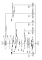
- the controller 32 is configured so that the heating mode can be executed even while the vehicle is connected to an external power source and the battery is charged. In this case, the controller 32 determines in step S1 in FIG. 4 whether the vehicle is currently plugged in and whether there is a heating request (input operation for starting the heating mode) by the user. If not, or if there is no heating request, the process proceeds from step S1 to step S13, where it is determined whether or not the outdoor heat exchanger 7 is frosted. The operation of the industrial air conditioner 1 is stopped. Moreover, when the outdoor heat exchanger 7 is frosted, it progresses to step S15, transfers to a defrost mode, and performs the defrost operation of the outdoor heat exchanger 7. FIG. In addition, the frost formation determination of the outdoor heat exchanger 7 in step S13 and the defrosting mode in step S15 will be described in detail later.
- step S1 determines whether or not the outdoor heat exchanger 7 is frosted.
- moisture in the outside air adheres to the outdoor heat exchanger 7 as frost in the heating mode.
- frost grows, heat exchange between the outdoor heat exchanger 7 and the outside air that is ventilated is significantly hindered, and air conditioning performance is deteriorated.
- the controller 32 obtains the current refrigerant evaporation temperature TXO of the outdoor heat exchanger 7 obtained from the outdoor heat exchanger pressure sensor 56, and the outdoor in the non-frosting state where the outdoor air is not frosted on the outdoor heat exchanger 7 in a low humidity environment. Based on the refrigerant evaporation temperature TXObase of the heat exchanger 7, the frosting state of the outdoor heat exchanger 7 is determined. In this case, the controller 32 determines the refrigerant evaporation temperature TXObase of the outdoor heat exchanger 7 at the time of non-frosting using the following equation (V).
- Tam which is a parameter of the formula (V) is the outside air temperature obtained from the outside air temperature sensor 33
- NC is the rotation speed of the compressor 2
- BLV is the blower voltage of the indoor blower 27
- VSP is obtained from the vehicle speed sensor 52. It is a vehicle speed
- k1 to k4 are coefficients, and are obtained in advance by experiments.
- the outside air temperature Tam is an index indicating the intake air temperature of the outdoor heat exchanger 7.
- the index indicating the intake air temperature of the outdoor heat exchanger 7 is not limited to the outdoor air temperature Tam.
- the rotational speed NC of the compressor 2 is an index indicating the refrigerant flow rate in the refrigerant circuit R. The higher the rotational speed NC (the higher the refrigerant flow rate), the lower the TXObase. Therefore, the coefficient k2 is a negative value.
- the blower voltage BLV is an index indicating the amount of air passing through the radiator 4.
- the index indicating the amount of air passing through the radiator 4 is not limited to this and may be the blower air amount of the indoor blower 27 or the air mix damper 28 opening SW.
- the vehicle speed VSP is an index indicating the passing air speed of the outdoor heat exchanger 7. The lower the vehicle speed VSP (the lower the passing air speed of the outdoor heat exchanger 7), the lower the TXObase. Therefore, the coefficient k4 is a positive value.
- the outdoor fan voltage FANVout of the outdoor blower 15 is used as an index indicating the passing air speed of the outdoor heat exchanger 7.
- the outside air temperature Tam, the rotational speed NC of the compressor 2, the blower voltage BLV of the indoor blower 27, and the vehicle speed VSP are used as parameters of the formula (V). May be added as a parameter.
- the target blowout temperature TAO, the rotational speed NC of the compressor 2, the blower air volume of the indoor blower 27, the inlet air temperature of the radiator 4 and the radiator temperature Tci of the radiator 4 can be considered. The larger the value, the lower the TXObase.
- the parameters of the formula (V) are not limited to all of the above, and any one of them or a combination thereof may be used.
- step S10 defrosting mode of outdoor heat exchanger If the outdoor heat exchanger 7 is frosted in step S3 (same as in step S13), the process proceeds to step S10 (same as in step S15) to defrost. Run the mode.
- the controller 32 opens the solenoid valve 24 and the solenoid valve 21, and closes the solenoid valve 22 and the solenoid valve 17. And the defrost operation which operates the compressor 2 with the electric power from the electric power from an external power supply or the battery charged with the external power supply is performed.
- the high-temperature and high-pressure gas refrigerant (hot gas) discharged from the compressor 2 passes through the electromagnetic valve 24 and the refrigerant pipe 13H, and directly flows from the refrigerant pipe 13I to the outdoor heat exchanger 7 via the check valve 45. It becomes a state to do. Thereby, since the outdoor heat exchanger 7 is heated, frost is thawed and removed.
- the refrigerant discharged from the outdoor heat exchanger 7 enters the refrigerant pipe 13D from the refrigerant pipe 13A through the electromagnetic valve 21, and is sucked into the compressor 2 through the refrigerant pipe 13B. And when predetermined time passes since the start of defrost mode, controller 32 complete
- step S3 Prediction of frost formation of outdoor heat exchanger
- the controller 32 proceeds to step S4 and determines whether or not the outdoor heat exchanger 7 is predicted to be frosted this time.
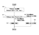
- FIG. 5 shows an example of a flowchart of frost formation prediction in step S4.
- step S16 of FIG. 5 the controller 32 calculates the non-frosting maximum heating capacity prediction value TGQhpNfst by the calculation of the above-described formula (III).
- the required heating capacity Qtgt is calculated according to (II) described above, and it is determined in step S17 whether or not the predicted non-frosting maximum heating capacity TGQhpNfst is smaller than the required heating capacity Qtgt- ⁇ 1 (TGQhpNfst ⁇ (Qtgt ⁇ 1). )).
- step S18 if the predicted value TGQhpNfst without frost formation is smaller than the value (Qtgt- ⁇ 1) close to the required heating capacity, the process proceeds to step S18 and the radiator 4 is heated by the operation of the compressor 2. It is predicted that the outdoor heat exchanger 7 will be frosted.
- TGQhpNfst ⁇ (Qtgt ⁇ 1) the process proceeds to step S19 and it is predicted that no frost formation will occur.
- step S18 if the controller 32 predicts that frost formation will occur in step S18, the process proceeds from step S4 to step S5 to calculate the required heating capacity Qtgt again by equation (II), and in step S6 the heat medium circulation circuit 23
- the maximum heating capacity QmaxHTR which is the maximum heating capacity that can be generated, is taken in.
- the heat medium circulation circuit maximum heating capacity QmaxHTR is set in the controller 32 in advance.
- the controller 32 compares the required heating capacity Qtgt with the heating medium circulation circuit maximum heating capacity QmaxHTR in step S7, and the heating medium circulation circuit maximum heating capacity QmaxHTR is insufficient with respect to the required heating capacity Qtgt in the cold season, for example.
- the process proceeds to step S8, and the target heating capacity Qhpr of the radiator 4 which is the required heating capacity by the radiator 4 is calculated by the following formula (VI).
- Qhpr Qtgt ⁇ QmaxHTR (VI) That is, in Formula (VI), the amount of heat medium circulation circuit maximum heating capacity QmaxHTR that is insufficient with respect to the required heating capacity Qtgt is set as the target heating capacity Qhpr of the radiator 4.
- the controller 32 then heats the vehicle interior by heat generated from the heat medium-air heat exchanger 40 and the radiator 4 in the heat medium circuit 23 in step S9.
- the compressor 2 and other devices of the refrigerant circuit R are operated so as to generate the target heating capacity Qhpr (Qtgt ⁇ QmaxHTR).
- the controller 32 supplements the heat medium circulation circuit maximum heating capacity QmaxHTR with respect to the required heating capacity Qtgt by heating by the radiator 4 of the refrigerant circuit R.
- pre-air conditioning (heating) in the passenger compartment is reliably realized.
- the controller 32 causes the refrigerant evaporation temperature TXO of the outdoor heat exchanger 7 to be lower than the outside air temperature Tam, and the difference between them is within a predetermined value A (positive value) ((Tam ⁇ TXO) ⁇ A).
- the compressor 2 is operated with a limitation on the number of rotations.
- the outdoor heat exchange is also performed. Prevents frosting on vessel 7.
- an operation of raising the temperature in the passenger compartment may be performed by extending the pre-air conditioning (heating) time.
- the vehicle interior is heated by normal heat pump operation by the radiator 4. In this case, heating by the heat medium circulation circuit 23 is stopped (the heat medium heating electric heater 35 and the circulation pump 30 are not energized).
- the controller 32 executes the heating mode in the so-called plug-in state in which power is supplied from the external power source to the compressor 2 or the battery that supplies power to drive the compressor 2, the outdoor heat When frost formation on the exchanger 7 is predicted, heating by the heat medium circulation circuit 23 is performed. Therefore, when the vehicle interior is preheated (pre-air-conditioning) during plug-in, the frost formation on the outdoor heat exchanger 7 is performed. Thus, the vehicle interior heating is performed by the heat medium circulation circuit 23 while preventing or suppressing the above, and the load during the subsequent traveling can be reduced. This makes it possible to extend the travel distance of the vehicle (electric vehicle or hybrid vehicle) while maintaining a comfortable temperature in the vehicle interior after the start of travel.
- the controller 32 executes heating by the radiator 4 when the heating capacity by the heat medium circulation circuit 23 is insufficient with respect to the required heating capacity Qtgt, so-called pre-air-conditioning (heating) in the cold season or at night is not hindered. It can be realized. Further, when the maximum heating capacity QmaxHTR of the heat medium circulation circuit 23 by the heat medium circulation circuit 23 satisfies the required heating capacity Qtgt, the compressor 2 is not operated, so that frost formation on the outdoor heat exchanger 7 is reliably prevented. Will be.
- the controller 32 compares the required heating capacity Qtgt with the heat medium circulation circuit maximum heating capacity QmaxHTR that can be generated by the heat medium circulation circuit 23, and the heat medium circulation circuit maximum heating capacity QmaxHTR is less than the required heating capacity Qtgt. Is supplemented by heating (Qhpr) of the radiator 4, it is possible to realize heating capacity supplementation by the accurate radiator 4.
- the controller 32 controls the rotational speed of the compressor 2 so that the refrigerant evaporation temperature TXO in the outdoor heat exchanger 7 is lower than the outdoor air temperature Tam and the difference between them is within a predetermined value A. Frosting on the exchanger 7 is effectively prevented or suppressed.
- the controller 32 performs the heating by the radiator 4 without performing the heating by the heat medium circulation circuit 23, so that the heating for the plug-in is performed. Reduction of power consumption can also be realized without any trouble by heat pump operation.
- the controller 32 calculates a non-frosting maximum heating capacity prediction value TGQhpNfst, which is a target value of the maximum heating capacity that can be generated by the radiator 4 within a range where the outdoor heat exchanger 7 does not frost, and this non-frosting maximum heating.
- TGQhpNfst is a target value of the maximum heating capacity that can be generated by the radiator 4 within a range where the outdoor heat exchanger 7 does not frost, and this non-frosting maximum heating.
- the controller 32 calculates the frost-free maximum heating capacity predicted value TGQhpNfst based on the outside air temperature Tam or adds the time, solar radiation, rainfall, position, and weather conditions to the outside air temperature Tam.
- the frostless maximum heating capacity predicted value TGQhpNfst is accurately estimated, that is, as a result, the frost point is accurately estimated to prevent frost formation on the outdoor heat exchanger 7 during plug-in more effectively, or It becomes possible to suppress.
- the auxiliary heating means includes a heat medium-air heat exchanger 40 for heating the air supplied from the air flow passage to the vehicle interior, a heat medium heating electric heater 35, and a circulation pump 30. Since the heat medium heated by the heat medium heating electric heater 35 is constituted by the heat medium circulation circuit 23 that circulates the heat medium heated by the circulation pump 30 to the heat medium-air heat exchanger 40, an electrically safer vehicle interior heating is realized. Will be able to.
- FIG. 7 shows a flowchart of another embodiment of the frost formation prediction in step S4 of FIG. 4 shown in FIG.
- the other controls are the same as those shown in FIGS. (7-4)
- the controller 32 firstly uses step (S20) in FIG. That is, when the frost is not generated in the outdoor heat exchanger 7, the non-frosting required refrigerant evaporation temperature TXObaseQtgt which is the refrigerant evaporation temperature of the outdoor heat exchanger 7 for realizing the required heating capacity Qtgt is predicted and calculated.
- TXObaseQtgt f (Tam, Qtgt) (VIII)
- Tam is the aforementioned outside temperature detected by the outside temperature sensor 33.
- the controller 32 causes the outdoor heat exchanger 7 to generate frost from the outside air temperature Tam detected by the outside air temperature sensor 33 and the outside air humidity of the vehicle detected by the outside air humidity sensor 34.
- the frost point Tfrost which is the temperature of the outside air around the vessel 7 (the temperature at which the water vapor pressure in the outside air becomes equal to the saturated water vapor pressure of ice) is calculated. Since the calculation method of this frost point Tfrost is a common method, description is abbreviate
- step S21 it is determined whether or not the required frost-free refrigerant evaporation temperature TXObaseQtgt is smaller than the frost point Tfrost + ⁇ 2 (TXObaseQtgt ⁇ (Tfrost + ⁇ 2)).
- the process proceeds to step S22, and heating by the radiator 4 is performed by the operation of the compressor 2. It is predicted that the exchanger 7 will be frosted. If TXObaseQtgt ⁇ (Tfrost + ⁇ 2), the process proceeds to step S23 and it is predicted that frost will not be formed.
- the controller 32 calculates the non-frosting required refrigerant evaporation temperature TXObaseQtgt which is the refrigerant evaporation temperature of the outdoor heat exchanger when the required heating capacity Qtgt is realized, and the non-frosting required refrigerant evaporation temperature TXObaseQtgt is calculated.
- the outdoor heat exchanger in the plug-in is based on the frost point Tfrost at which frost is generated in the outdoor heat exchanger 7 by predicting frost formation on the outdoor heat exchanger 7 when the frost point Tfrost is lower than or near the frost point Tfrost. 7 can be effectively prevented or suppressed.
- the controller 32 calculates the non-frosting required refrigerant evaporation temperature TXObaseQtgt based on the outside air temperature Tam and the required heating capacity Qtgt, the non-attachment that realizes the required heating capacity Qtgt when the outdoor heat exchanger 7 is not frosted.
- the frost required refrigerant evaporation temperature TXObaseQtgt is accurately estimated, and frost formation on the outdoor heat exchanger 7 during plug-in can be more effectively prevented or suppressed.
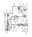
- FIG. 8 shows another configuration diagram of the vehicle air conditioner 1 of the present invention.
- the outdoor heat exchanger 7 is not provided with the receiver dryer section 14 and the supercooling section 16, and the refrigerant pipe 13 ⁇ / b> A exiting from the outdoor heat exchanger 7 is connected via the electromagnetic valve 17 and the check valve 18. It is connected to the refrigerant pipe 13B.
- the refrigerant pipe 13D branched from the refrigerant pipe 13A is connected to the refrigerant pipe 13C on the downstream side of the internal heat exchanger 19 via the electromagnetic valve 21.
- the present invention is also effective in the vehicle air conditioner 1 of the refrigerant circuit R that employs the outdoor heat exchanger 7 that does not include the receiver dryer section 14 and the supercooling section 16.
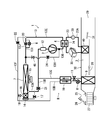
- FIG. 9 shows another configuration diagram of the vehicle air conditioner 1 of the present invention.
- the refrigerant circuit R in this embodiment is the same as that shown in FIG.
- the heat medium-air heat exchanger 40 of the heat medium circuit 23 is disposed upstream of the radiator 4 and downstream of the air mix damper 28 with respect to the air flow in the air flow passage 3.
- Other configurations are the same as those in FIG.
- the present invention is also effective in the vehicle air conditioner 1 in which the heat medium-air heat exchanger 40 is arranged on the upstream side of the radiator 4.
- the heat medium in the heat medium circulation circuit 23 is used. The problem caused by the low temperature is not caused. This facilitates cooperative heating with the radiator 4 and eliminates the need for so-called preliminary operation in which the heat medium is heated in advance. However, air that has passed through the heat medium-air heat exchanger 40 flows into the radiator 4.
- the heat medium-air heat exchanger 40 is arranged on the downstream side of the radiator 4 with respect to the air flow in the air flow passage 3 as shown in FIG. 1 and FIG. 8, the heat medium-air as shown in FIG. Compared with the case where the heat exchanger 40 is arranged upstream, the air heated by the heat medium-air heat exchanger 40 does not flow into the radiator 4, and the temperature difference between the temperature of the radiator 4 and the air Is ensured, and the heat exchange performance of the radiator 4 can be prevented from lowering.
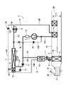
- FIG. 10 shows still another configuration diagram of the vehicle air conditioner 1 of the present invention.
- the basic configurations of the refrigerant circuit R and the heat medium circulation circuit 23 in this embodiment are the same as those in FIG. 1, but a heat medium-refrigerant heat exchanger 70 is provided in the heat medium circulation circuit 23.
- the heat medium-refrigerant heat exchanger 70 exchanges heat between the heat medium pipe 23A exiting the circulation pump 30 and the refrigerant pipe 13E exiting the radiator 4 of the refrigerant circuit R.
- the heat medium discharged from the circulation pump 30 is configured to receive a heating action from the refrigerant discharged from the radiator 4.
- heat can be recovered from the refrigerant that has passed through the radiator 4 to the heat medium that circulates through the heat medium circuit 23.
- the heat medium circulation circuit 23 is provided with the heat medium-refrigerant heat exchanger 70 that recovers heat from the refrigerant that has passed through the radiator 4, so that the heat of the refrigerant that has exited the radiator 4 can be transferred to the heat medium circuit. It is possible to recover the heat medium flowing in the heat transfer medium 23 and transport it to the heat medium-air heat exchanger 40 to perform more efficient heating assistance.
- FIG. 11 shows still another configuration diagram of the vehicle air conditioner 1 of the present invention.
- the refrigerant circuit R and the heat medium circulation circuit 23 of this embodiment are the same as in the case of FIG. 10 except that the heat medium-air heat exchanger 40 of the heat medium circulation circuit 23 corresponds to the air flow in the air flow passage 3. Further, it is disposed upstream of the radiator 4 and downstream of the air mix damper 28. Also with such a configuration, the heat of the refrigerant that has exited the radiator 4 is recovered by the heat medium-refrigerant heat exchanger 70 to the heat medium flowing in the heat medium circuit 23, and the heat medium-air heat exchanger 40. It becomes possible to carry out more efficient heating assistance.
- FIG. 12 shows still another configuration diagram of the vehicle air conditioner 1 of the present invention.
- the piping configuration of the refrigerant circuit R and the heat medium circulation circuit 23 in this embodiment is basically the same as that in FIG. 1, but the radiator 4 is not provided in the air flow passage 3 and is arranged outside thereof. Has been. Instead, the radiator 4 is provided with a heat medium-refrigerant heat exchanger 74 in this case in a heat exchange relationship.
- This heat medium-refrigerant heat exchanger 74 is connected to the heat medium pipe 23A between the circulation pump 30 of the heat medium circulation circuit 23 and the heat medium heating electric heater 35, and the heat medium of the heat medium circulation circuit 23-
- the air heat exchanger 40 is provided in the air flow passage 3.
- the heating medium heating electric heater 35 is energized to heat the heating medium flowing in the heating medium circuit 23A.
- the heat medium circulation circuit 23 is employed as the auxiliary heating unit.
- the auxiliary heating unit may be configured by a normal electric heater (for example, a PTC heater) 73.
- FIG. 13 shows a configuration example corresponding to FIG. 1
- FIG. 14 shows a configuration example corresponding to FIG. 13 and 14, the heat medium circulation circuit 23 of FIGS. 1 and 8 is replaced with an electric heater 73 in this case.
- controller 32 controls the energization of the electric heater 73 instead of the circulation pump 30 and the heat medium heating electric heater 35 of the heat medium circulation circuit 23, and the same as described above. Since the heating capacity of the radiator 4 is complemented by heat generation, detailed description thereof is omitted. Thus, the air supplied to the passenger compartment may be heated by the electric heater 73. According to such a configuration, there is an advantage that the configuration is simplified as compared with the case where the heat medium circulation circuit 23 is used.
- this electric heater 73 may be arranged on the air upstream side of the radiator 4 in FIGS. 13 and 14 as in the case of FIG. 9, and in that case, the electric heater 73 is placed in the vehicle interior at the beginning of energization of the electric heater 73. This has the effect of eliminating the inconvenience that the temperature of the supplied air decreases.
- the controller 32 serving as the frost formation estimation means of the outdoor heat exchanger 7 determines the frost formation on the outdoor heat exchanger 7 based on the frost point Tfrost and the refrigerant evaporation temperature TXO of the outdoor heat exchanger 7.
- the refrigerant evaporating temperature TXO (or the refrigerant evaporating pressure PXO) of the outdoor heat exchanger 7 and the outdoor heat exchanger 7 at the time of non-frosting are not limited thereto.
- TXObase refrigerant evaporation temperature
- PXObase refrigerant evaporation pressure
- the present invention is applied to the vehicle air conditioner 1 that switches between and executes the heating mode, the dehumidifying heating mode, the dehumidifying and cooling mode, and the cooling mode.
- the present invention is not limited thereto, and only the heating mode is performed. In addition, the present invention is effective.
Landscapes
- Engineering & Computer Science (AREA)
- Physics & Mathematics (AREA)
- Mechanical Engineering (AREA)
- Thermal Sciences (AREA)
- General Engineering & Computer Science (AREA)
- Life Sciences & Earth Sciences (AREA)
- Sustainable Development (AREA)
- Sustainable Energy (AREA)
- Air-Conditioning For Vehicles (AREA)
Abstract
Description
コントローラ32により或いは空調操作部53へのマニュアル操作により暖房モードが選択されると、コントローラ32は電磁弁21を開放し、電磁弁17、電磁弁22、電磁弁20及び電磁弁24を閉じる。そして、圧縮機2、及び、各送風機15、27を運転し、エアミックスダンパ28は室内送風機27から吹き出された空気が放熱器4及び熱媒体-空気熱交換器40に通風される状態とする。これにより、圧縮機2から吐出された高温高圧のガス冷媒は放熱器4に流入する。放熱器4には空気流通路3内の空気が通風されるので、空気流通路3内の空気は放熱器4内の高温冷媒により加熱され、一方、放熱器4内の冷媒は空気に熱を奪われて冷却され、凝縮液化する。
次に、除湿暖房モードでは、コントローラ32は上記暖房モードの状態において電磁弁22を開放する。これにより、放熱器4を経て冷媒配管13Eを流れる凝縮冷媒の一部が分流され、電磁弁22を経て冷媒配管13F及び13Bより内部熱交換器19を経て室内膨張弁8に至るようになる。室内膨張弁8にて冷媒は減圧された後、吸熱器9に流入して蒸発する。このときの吸熱作用で室内送風機27から吹き出された空気中の水分が吸熱器9に凝結して付着するので、空気は冷却され、且つ、除湿される。
次に、内部サイクルモードでは、コントローラ32は上記除湿暖房モードの状態において室外膨張弁6を全閉とする(全閉位置)と共に、電磁弁21も閉じる。この室外膨張弁6と電磁弁21が閉じられることにより、室外熱交換器7への冷媒の流入、及び、室外熱交換器7からの冷媒の流出は阻止されることになるので、放熱器4を経て冷媒配管13Eを流れる凝縮冷媒は電磁弁22を経て冷媒配管13Fに全て流れるようになる。そして、冷媒配管13Fを流れる冷媒は冷媒配管13Bより内部熱交換器19を経て室内膨張弁8に至る。室内膨張弁8にて冷媒は減圧された後、吸熱器9に流入して蒸発する。このときの吸熱作用で室内送風機27から吹き出された空気中の水分が吸熱器9に凝結して付着するので、空気は冷却され、且つ、除湿される。
次に、除湿冷房モードでは、コントローラ32は電磁弁17を開放し、電磁弁21、電磁弁22、電磁弁20及び電磁弁24を閉じる。そして、圧縮機2、及び、各送風機15、27を運転し、エアミックスダンパ28は室内送風機27から吹き出された空気が放熱器4及び熱媒体-空気熱交換器40に通風される状態とする。これにより、圧縮機2から吐出された高温高圧のガス冷媒は放熱器4に流入する。放熱器4には空気流通路3内の空気が通風されるので、空気流通路3内の空気は放熱器4内の高温冷媒により加熱され、一方、放熱器4内の冷媒は空気に熱を奪われて冷却され、凝縮液化していく。
次に、冷房モードでは、コントローラ32は上記除湿冷房モードの状態において電磁弁20を開き(この場合、室外膨張弁6は全開(弁開度を制御上限)を含む何れの弁開度でもよい)、エアミックスダンパ28は放熱器4及び熱媒体-空気熱交換器40に空気が通風されない状態とする。これにより、圧縮機2から吐出された高温高圧のガス冷媒は放熱器4に流入する。放熱器4には空気流通路3内の空気は通風されないので、ここは通過するのみとなり、放熱器4を出た冷媒は冷媒配管13Eを経て電磁弁20及び室外膨張弁6に至る。
次に、車両(電気自動車)の走行中における前記暖房モード時の圧縮機2及び室外膨張弁6の制御と、当該暖房モードでの熱媒体循環回路23による補助加熱について説明する。
コントローラ32は下記式(I)から目標吹出温度TAOを算出する。この目標吹出温度TAOは、吹出口29から車室内に吹き出される空気温度の目標値である。
TAO=(Tset-Tin)×K+Tbal(f(Tset、SUN、Tam))・・(I)
ここで、Tsetは空調操作部53で設定された車室内の設定温度、Tinは内気温度センサ37が検出する車室内空気の温度、Kは係数、Tbalは設定温度Tsetや、日射センサ51が検出する日射量SUN、外気温度センサ33が検出する外気温度Tamから算出されるバランス値である。そして、一般的に、この目標吹出温度TAOは外気温度Tamが低い程高く、外気温度Tamが上昇するに伴って低下する。
また、コントローラ32は、この暖房モードにおいて放熱器4による暖房能力が不足すると判断した場合、熱媒体加熱電気ヒータ35に通電して発熱させ、循環ポンプ30を運転することにより、熱媒体循環回路23による加熱を実行する。
TGQhpNfst=f(Tam) ・・(III)
ここで、Tamは外気温度センサ33が検出する前述した外気温度、Teは吸熱器温度センサ48が検出する吸熱器9の温度、Cpaは放熱器4に流入する空気の比熱[kj/kg・K]、ρは放熱器4に流入する空気の密度(比体積)[kg/m3]、Qairは放熱器4を通過する風量[m3/h](室内送風機27のブロワ電圧BLV等から推定)である。
TGQHTR=Qtgt-TGQhpNfst ・・(IV)
即ち、無着霜最大暖房能力予測値TGQhpNfstが要求暖房能力Qtgtより不足する分を、熱媒体循環回路23の目標暖房能力TGQHTRとする。
次に、図4、図5を参照しながら車両(電気自動車)のプラグイン中に前記暖房モードとされ、車室内をプレ空調(暖房)するときの熱媒体循環回路23と冷媒回路Rの制御について説明する。
コントローラ32はステップS3(前記ステップS13も同様)でその機能としての着霜推定手段により、室外熱交換器7への着霜状態を判定(推定)する。次に、室外熱交換器7の着霜状態の判定例を説明する。
=k1×Tam+k2×NC+k3×BLV+k4×VSP・・(V)
ここで、式(V)のパラメータであるTamは外気温度センサ33から得られる前記外気温度、NCは圧縮機2の回転数、BLVは室内送風機27のブロワ電圧、VSPは車速センサ52から得られる車速であり、k1~k4は係数で、予め実験により求めておく。
また、上記圧縮機2の回転数NCは冷媒回路R内の冷媒流量を示す指標であり、回転数NCが高い程(冷媒流量が多い程)、TXObaseは低くなる傾向となる。従って、係数k2は負の値となる。
また、上記ブロワ電圧BLVは放熱器4の通過風量を示す指標であり、ブロワ電圧BLVが高い程(放熱器4の通過風量が大きい程)、TXObaseは低くなる傾向となる。従って、係数k3は負の値となる。尚、放熱器4の通過風量を示す指標としてはこれに限らず、室内送風機27のブロワ風量やエアミックスダンパ28開度SWでもよい。
また、上記車速VSPは室外熱交換器7の通過風速を示す指標であり、車速VSPが低い程(室外熱交換器7の通過風速が低い程)、TXObaseは低くなる傾向となる。従って、係数k4は正の値となる。
ステップS3(前記ステップS13も同様)で室外熱交換器7に着霜している場合、ステップS10(前記ステップS15も同様)に進んで除霜モードを実行する。コントローラ32はステップS10(ステップS15)の除霜モードでは、電磁弁24と電磁弁21を開き、電磁弁22及び電磁弁17を閉じる。そして、外部電源からの電力、或いは、外部電源で充電されているバッテリからの電力で圧縮機2を運転する除霜運転を行う。これにより、圧縮機2から吐出された高温高圧のガス冷媒(ホットガス)は、電磁弁24を経て冷媒配管13Hを通り、逆止弁45を経て冷媒配管13Iから室外熱交換器7に直接流入する状態となる。これにより、室外熱交換器7は加熱されるので、霜は融解除去される。
一方、ステップS3で差ΔTXOが着霜検知閾値ΔT1以下(ΔTXO≦ΔT1)で室外熱交換器7に着霜していないと判定された場合、コントローラ32はステップS4に進んで今度は室外熱交換器7に着霜すると予測されるか否か判断する。図5はステップS4における着霜予測のフローチャートの一例を示している。
Qhpr=Qtgt-QmaxHTR ・・(VI)
即ち、式(VI)は熱媒体循環回路最大暖房能力QmaxHTRが要求暖房能力Qtgtに対して不足する分を、放熱器4の目標暖房能力Qhprとする。
TGQHTR=Qtgt ・・(VII)
(7-4)室外熱交換器の着霜予測の他の例
この場合、コントローラ32は先ず図7のステップS20で、下記式(VIII)を用いて室外熱交換器7の無着霜時に、即ち、室外熱交換器7に霜が生じていないときに要求暖房能力Qtgtを実現するための室外熱交換器7の冷媒蒸発温度である無着霜時要求冷媒蒸発温度TXObaseQtgtを予測して算出する。
TXObaseQtgt=f(Tam、Qtgt) ・・(VIII)
ここで、Tamは外気温度センサ33が検出する前述した外気温度である。
2 圧縮機
3 空気流通路
4 放熱器
6 室外膨張弁
7 室外熱交換器
8 室内膨張弁
9 吸熱器
11 蒸発能力制御弁
17、20、21、22、24 電磁弁
23 熱媒体循環回路(補助加熱手段)
26 吸込切換ダンパ
27 室内送風機(ブロワファン)
28 エアミックスダンパ
30 循環ポンプ(循環手段)
32 コントローラ(制御手段)
35 熱媒体加熱電気ヒータ(電気ヒータ)
40 熱媒体-空気熱交換器
R 冷媒回路
Claims (10)
- 冷媒を圧縮する圧縮機と、
車室内に供給する空気が流通する空気流通路と、
冷媒を放熱させて前記空気流通路から前記車室内に供給する空気を加熱するための放熱器と、
冷媒を吸熱させて前記空気流通路から前記車室内に供給する空気を冷却するための吸熱器と、
前記車室外に設けられて冷媒を放熱又は吸熱させる室外熱交換器と、
制御手段とを備え、
該制御手段により少なくとも、前記圧縮機から吐出された冷媒を前記放熱器にて放熱させ、放熱した当該冷媒を減圧した後、前記室外熱交換器にて吸熱させる暖房モードを実行する車両用空気調和装置において、
前記空気流通路から前記車室内に供給する空気を加熱するための補助加熱手段を備え、
前記制御手段は、前記室外熱交換器への着霜を推定する着霜推定手段を有し、外部電源から前記圧縮機、若しくは、当該圧縮機を駆動するために電力を供給するバッテリに給電されている状態において前記暖房モードを実行する際、前記着霜推定手段の推定に基づき、前記室外熱交換器への着霜が予測される場合、前記補助加熱手段による加熱を実行することを特徴とする車両用空気調和装置。 - 前記制御手段は、前記補助加熱手段による暖房能力が要求暖房能力Qtgtに対して不足する場合、前記放熱器による暖房を実行することを特徴とする請求項1に記載の車両用空気調和装置。
- 前記制御手段は、前記要求暖房能力Qtgtと前記補助加熱手段が発生可能な最大暖房能力とを比較し、該最大暖房能力が前記要求暖房能力Qtgtより不足する分を前記放熱器の暖房により補完することを特徴とする請求項2に記載の車両用空気調和装置。
- 前記制御手段は、前記室外熱交換器における冷媒蒸発温度が外気温度より低く、且つ、それらの差が所定値以内となるように前記圧縮機を制御することを特徴とする請求項3に記載の車両用空気調和装置。
- 前記制御手段は、前記着霜状態推定手段の推定に基づき、前記室外熱交換器に着霜しないと予測される場合、前記補助加熱手段による暖房を行うこと無く、前記放熱器による暖房を実行することを特徴とする請求項1乃至請求項4のうちの何れかに記載の車両用空気調和装置。
- 前記着霜推定手段は、前記室外熱交換器に着霜しない範囲で前記放熱器が発生可能な最大暖房能力の目標値である無着霜最大暖房能力予測値TGQhpNfstを算出し、
該無着霜最大暖房能力予測値TGQhpNfstが、要求暖房能力Qtgt又はそれに近い値より小さくなる場合、前記室外熱交換器に着霜すると予測することを特徴とする請求項1乃至請求項5のうちの何れかに記載の車両用空気調和装置。 - 前記着霜推定手段は、外気温度に基づき、若しくは、それに時刻、日射、降雨、位置、気象条件を加えて前記無着霜最大暖房能力予測値TGQhpNfstを算出することを特徴とする請求項6に記載の車両用空気調和装置。
- 前記着霜推定手段は、要求暖房能力Qtgtを実現するときの前記室外熱交換器の冷媒蒸発温度である無着霜時要求冷媒蒸発温度TXObaseQtgtを算出し、
該無着霜時要求冷媒蒸発温度TXObaseQtgtが、霜点Tfrost又はそれに近い温度より低くなる場合、前記室外熱交換器に着霜すると予測することを特徴とする請求項1乃至請求項5のうちの何れかに記載の車両用空気調和装置。 - 前記着霜推定手段は、外気温度と前記要求暖房能力Qtgtに基づき、前記無着霜時要求冷媒蒸発温度TXObaseQtgtを算出することを特徴とする請求項8に記載の車両用空気調和装置。
- 前記空気流通路から前記車室内に供給する空気を加熱するための熱媒体-空気熱交換器と、電気ヒータと、循環手段とを有し、前記電気ヒータにより加熱された熱媒体を前記循環手段により前記熱媒体-空気熱交換器に循環する熱媒体循環回路から前記補助加熱手段を構成したことを特徴とする請求項1乃至請求項9のうちの何れかに記載の車両用空気調和装置。
Priority Applications (4)
| Application Number | Priority Date | Filing Date | Title |
|---|---|---|---|
| DE112014003874.1T DE112014003874B4 (de) | 2013-08-23 | 2014-08-21 | Fahrzeugklimaanlage |
| CN201480046670.5A CN105473357B (zh) | 2013-08-23 | 2014-08-21 | 车辆用空调装置 |
| US14/913,264 US10239382B2 (en) | 2013-08-23 | 2014-08-21 | Vehicle air conditioner |
| US15/875,674 US10703169B2 (en) | 2013-08-23 | 2018-01-19 | Vehicle air conditioner |
Applications Claiming Priority (2)
| Application Number | Priority Date | Filing Date | Title |
|---|---|---|---|
| JP2013-173235 | 2013-08-23 | ||
| JP2013173235A JP6192434B2 (ja) | 2013-08-23 | 2013-08-23 | 車両用空気調和装置 |
Related Child Applications (2)
| Application Number | Title | Priority Date | Filing Date |
|---|---|---|---|
| US14/913,264 A-371-Of-International US10239382B2 (en) | 2013-08-23 | 2014-08-21 | Vehicle air conditioner |
| US15/875,674 Division US10703169B2 (en) | 2013-08-23 | 2018-01-19 | Vehicle air conditioner |
Publications (1)
| Publication Number | Publication Date |
|---|---|
| WO2015025907A1 true WO2015025907A1 (ja) | 2015-02-26 |
Family
ID=52483678
Family Applications (1)
| Application Number | Title | Priority Date | Filing Date |
|---|---|---|---|
| PCT/JP2014/071835 Ceased WO2015025907A1 (ja) | 2013-08-23 | 2014-08-21 | 車両用空気調和装置 |
Country Status (5)
| Country | Link |
|---|---|
| US (2) | US10239382B2 (ja) |
| JP (1) | JP6192434B2 (ja) |
| CN (1) | CN105473357B (ja) |
| DE (1) | DE112014003874B4 (ja) |
| WO (1) | WO2015025907A1 (ja) |
Cited By (1)
| Publication number | Priority date | Publication date | Assignee | Title |
|---|---|---|---|---|
| US20180201088A1 (en) * | 2015-08-06 | 2018-07-19 | Denso Corporation | Air conditioning device for vehicle |
Families Citing this family (35)
| Publication number | Priority date | Publication date | Assignee | Title |
|---|---|---|---|---|
| JP5999637B2 (ja) * | 2012-11-09 | 2016-09-28 | サンデンホールディングス株式会社 | 車両用空気調和装置 |
| JP6005484B2 (ja) * | 2012-11-09 | 2016-10-12 | サンデンホールディングス株式会社 | 車両用空気調和装置 |
| JP6040099B2 (ja) * | 2013-05-28 | 2016-12-07 | サンデンホールディングス株式会社 | 車両用空気調和装置 |
| JP6125330B2 (ja) * | 2013-05-28 | 2017-05-10 | サンデンホールディングス株式会社 | 車両用空気調和装置 |
| JP6271195B2 (ja) * | 2013-09-18 | 2018-01-31 | サンデンホールディングス株式会社 | 車両用空気調和装置 |
| JP6207958B2 (ja) * | 2013-10-07 | 2017-10-04 | サンデンホールディングス株式会社 | 車両用空気調和装置 |
| JP6418779B2 (ja) * | 2014-05-08 | 2018-11-07 | サンデンホールディングス株式会社 | 車両用空気調和装置 |
| JP6470026B2 (ja) * | 2014-12-04 | 2019-02-13 | サンデンホールディングス株式会社 | 車両用空気調和装置 |
| TWI590571B (zh) * | 2014-12-08 | 2017-07-01 | 強生控制科技公司 | 可變速驅動器系統及冷卻系統 |
| US10457111B2 (en) * | 2015-02-04 | 2019-10-29 | Ford Global Technologies, Llc | Climate control system for a vehicle |
| CN104776630B (zh) * | 2015-04-28 | 2017-05-03 | 广东美的暖通设备有限公司 | 多联机系统 |
| JP6571430B2 (ja) * | 2015-07-21 | 2019-09-04 | サンデン・オートモーティブクライメイトシステム株式会社 | 車両用空気調和装置 |
| JP6738157B2 (ja) * | 2016-02-26 | 2020-08-12 | サンデン・オートモーティブクライメイトシステム株式会社 | 車両用空気調和装置 |
| JP6710061B2 (ja) * | 2016-02-26 | 2020-06-17 | サンデン・オートモーティブクライメイトシステム株式会社 | 車両用空気調和装置 |
| JP6565744B2 (ja) * | 2016-03-10 | 2019-08-28 | 株式会社デンソー | 空調装置 |
| CN109469966B (zh) * | 2016-06-13 | 2020-06-05 | 珠海格力电器股份有限公司 | 空调器压缩机电加热控制方法及装置 |
| CN106091249B (zh) * | 2016-06-13 | 2019-07-09 | 珠海格力电器股份有限公司 | 空调器压缩机电加热控制方法及装置 |
| US10603978B2 (en) * | 2016-07-20 | 2020-03-31 | Ford Global Technologies, Llc | Vehicle auxiliary HVAC system using a coolant loop for cooling a component and vehicle interior |
| KR101875651B1 (ko) * | 2016-09-13 | 2018-07-06 | 현대자동차 주식회사 | 차량용 히트 펌프 시스템 |
| FR3058783B1 (fr) * | 2016-11-17 | 2018-12-07 | Valeo Systemes Thermiques | Circuit de climatisation inversible indirect de vehicule automobile et procede de fonctionnement correspondant |
| KR102768964B1 (ko) * | 2016-12-19 | 2025-02-18 | 현대자동차주식회사 | 전기 자동차, 그를 포함하는 시스템 및 전기 자동차의 배터리 충전 방법 |
| JP6963405B2 (ja) * | 2017-04-26 | 2021-11-10 | サンデン・オートモーティブクライメイトシステム株式会社 | 車両用空気調和装置 |
| JP6884028B2 (ja) | 2017-04-26 | 2021-06-09 | サンデン・オートモーティブクライメイトシステム株式会社 | 車両用空気調和装置 |
| JP6917773B2 (ja) * | 2017-05-18 | 2021-08-11 | サンデン・オートモーティブクライメイトシステム株式会社 | 車両用空気調和装置 |
| FR3066584B1 (fr) * | 2017-05-19 | 2019-05-03 | Valeo Systemes Thermiques | Circuit de climatisation inversible indirect de vehicule automobile et procede de de gestion en mode pompe a chaleur |
| JP6863131B2 (ja) * | 2017-06-28 | 2021-04-21 | 株式会社デンソー | 空調装置 |
| JP6690611B2 (ja) * | 2017-07-31 | 2020-04-28 | 株式会社デンソー | ヒートポンプサイクル装置および弁装置 |
| JP6496434B1 (ja) * | 2017-10-02 | 2019-04-03 | カルソニックカンセイ株式会社 | 空調装置 |
| US11267315B2 (en) | 2017-10-02 | 2022-03-08 | Marelli Cabin Comfort Japan Corporation | Air-conditioning device |
| JP6925288B2 (ja) * | 2018-01-30 | 2021-08-25 | サンデン・オートモーティブクライメイトシステム株式会社 | 車両用空気調和装置 |
| US20190351740A1 (en) * | 2018-05-18 | 2019-11-21 | Nio Usa, Inc. | Use of an inside condenser to maximize total thermal system performance |
| JP7440761B2 (ja) * | 2020-04-16 | 2024-02-29 | ダイキン工業株式会社 | 開弁回路及びヒートポンプ装置 |
| CN112976999B (zh) * | 2021-04-12 | 2022-07-22 | 吉林大学 | 针对多热源直流储能装置的集成式热管理系统及控制方法 |
| JP2023000180A (ja) * | 2021-06-17 | 2023-01-04 | 株式会社デンソー | 車両用空調装置 |
| US20230288086A1 (en) * | 2022-03-14 | 2023-09-14 | Carrier Corporation | Systems and methods for defrost control in heat pumps |
Citations (6)
| Publication number | Priority date | Publication date | Assignee | Title |
|---|---|---|---|---|
| JPS60223940A (ja) * | 1984-04-23 | 1985-11-08 | Mitsubishi Heavy Ind Ltd | ヒ−トポンプ式空気調和機のフロスト検知装置 |
| JPH09142139A (ja) * | 1995-09-22 | 1997-06-03 | Denso Corp | 車両用空調装置 |
| JP2001324237A (ja) * | 2000-05-12 | 2001-11-22 | Denso Corp | 冷凍サイクル装置 |
| JP2011011686A (ja) * | 2009-07-03 | 2011-01-20 | Denso Corp | 車両用空調装置の制御方法 |
| JP2012176658A (ja) * | 2011-02-25 | 2012-09-13 | Sanden Corp | 車両用空気調和装置 |
| JP2013139252A (ja) * | 2011-12-05 | 2013-07-18 | Denso Corp | ヒートポンプサイクル |
Family Cites Families (12)
| Publication number | Priority date | Publication date | Assignee | Title |
|---|---|---|---|---|
| JPS5833038A (ja) * | 1981-08-24 | 1983-02-26 | Hitachi Ltd | 空冷ヒ−トポンプ式空調機の除霜制御 |
| JP3985384B2 (ja) | 1998-09-24 | 2007-10-03 | 株式会社デンソー | 冷凍サイクル装置 |
| JP4380077B2 (ja) * | 2000-09-27 | 2009-12-09 | 株式会社デンソー | 車両用空調装置 |
| KR20050105029A (ko) * | 2004-04-30 | 2005-11-03 | 엘지전자 주식회사 | 공기조화기의 제상운전방법 |
| JP4665878B2 (ja) * | 2006-09-15 | 2011-04-06 | パナソニック株式会社 | 電子部品搭載装置および電子部品搭載方法 |
| JP5092829B2 (ja) * | 2008-03-19 | 2012-12-05 | ダイキン工業株式会社 | 空気調和装置 |
| JP5126173B2 (ja) | 2009-07-13 | 2013-01-23 | 株式会社デンソー | 車両用空調装置 |
| DE102010025779A1 (de) | 2009-07-03 | 2011-01-13 | DENSO CORPORATION, Kariya-shi | Klimatisierungsvorrichtung für Fahrzeug und Verfahren zu deren Steuerung |
| JP5488218B2 (ja) | 2010-06-09 | 2014-05-14 | 日産自動車株式会社 | 車両用空調装置 |
| DE112012000522B4 (de) * | 2011-01-21 | 2020-12-17 | Sanden Holdings Corporation | Fahrzeugklimatisierungseinrichtung |
| US8977417B2 (en) * | 2012-10-19 | 2015-03-10 | Ford Global Technologies, Llc | System and method for controlling a vehicle having a single-wire actuator |
| EP2924368B1 (en) * | 2012-11-22 | 2019-02-06 | Mitsubishi Electric Corporation | Air conditioner and operation control method therefor |
-
2013
- 2013-08-23 JP JP2013173235A patent/JP6192434B2/ja active Active
-
2014
- 2014-08-21 DE DE112014003874.1T patent/DE112014003874B4/de active Active
- 2014-08-21 US US14/913,264 patent/US10239382B2/en active Active
- 2014-08-21 CN CN201480046670.5A patent/CN105473357B/zh active Active
- 2014-08-21 WO PCT/JP2014/071835 patent/WO2015025907A1/ja not_active Ceased
-
2018
- 2018-01-19 US US15/875,674 patent/US10703169B2/en active Active
Patent Citations (6)
| Publication number | Priority date | Publication date | Assignee | Title |
|---|---|---|---|---|
| JPS60223940A (ja) * | 1984-04-23 | 1985-11-08 | Mitsubishi Heavy Ind Ltd | ヒ−トポンプ式空気調和機のフロスト検知装置 |
| JPH09142139A (ja) * | 1995-09-22 | 1997-06-03 | Denso Corp | 車両用空調装置 |
| JP2001324237A (ja) * | 2000-05-12 | 2001-11-22 | Denso Corp | 冷凍サイクル装置 |
| JP2011011686A (ja) * | 2009-07-03 | 2011-01-20 | Denso Corp | 車両用空調装置の制御方法 |
| JP2012176658A (ja) * | 2011-02-25 | 2012-09-13 | Sanden Corp | 車両用空気調和装置 |
| JP2013139252A (ja) * | 2011-12-05 | 2013-07-18 | Denso Corp | ヒートポンプサイクル |
Cited By (2)
| Publication number | Priority date | Publication date | Assignee | Title |
|---|---|---|---|---|
| US20180201088A1 (en) * | 2015-08-06 | 2018-07-19 | Denso Corporation | Air conditioning device for vehicle |
| US10538138B2 (en) * | 2015-08-06 | 2020-01-21 | Denso Corporation | Air conditioning device for vehicle |
Also Published As
| Publication number | Publication date |
|---|---|
| JP2015039998A (ja) | 2015-03-02 |
| DE112014003874T5 (de) | 2016-05-25 |
| CN105473357A (zh) | 2016-04-06 |
| US20180141409A1 (en) | 2018-05-24 |
| US20160193896A1 (en) | 2016-07-07 |
| CN105473357B (zh) | 2017-10-24 |
| JP6192434B2 (ja) | 2017-09-06 |
| DE112014003874B4 (de) | 2022-10-27 |
| US10703169B2 (en) | 2020-07-07 |
| US10239382B2 (en) | 2019-03-26 |
Similar Documents
| Publication | Publication Date | Title |
|---|---|---|
| JP6192434B2 (ja) | 車両用空気調和装置 | |
| JP6192435B2 (ja) | 車両用空気調和装置 | |
| JP6125330B2 (ja) | 車両用空気調和装置 | |
| JP6040099B2 (ja) | 車両用空気調和装置 | |
| JP6125312B2 (ja) | 車両用空気調和装置 | |
| JP6223753B2 (ja) | 車両用空気調和装置 | |
| JP6339419B2 (ja) | 車両用空気調和装置 | |
| WO2019039153A1 (ja) | 車両用空気調和装置 | |
| WO2018198581A1 (ja) | 車両用空気調和装置 | |
| JP2014226979A (ja) | 車両用空気調和装置 | |
| WO2014084343A1 (ja) | 車両用空気調和装置 | |
| WO2020066719A1 (ja) | 車両用空気調和装置 | |
| WO2019181311A1 (ja) | 車両用制御システム | |
| JP6571430B2 (ja) | 車両用空気調和装置 | |
| WO2019058826A1 (ja) | 車両用空気調和装置 | |
| JP6047387B2 (ja) | 車両用空気調和装置 | |
| JP2019018708A (ja) | 車両用空気調和装置 | |
| JP6047388B2 (ja) | 車両用空気調和装置 | |
| WO2019181310A1 (ja) | 車両用空気調和装置 | |
| CN113811727A (zh) | 车辆用空气调节装置 |
Legal Events
| Date | Code | Title | Description |
|---|---|---|---|
| WWE | Wipo information: entry into national phase |
Ref document number: 201480046670.5 Country of ref document: CN |
|
| 121 | Ep: the epo has been informed by wipo that ep was designated in this application |
Ref document number: 14837973 Country of ref document: EP Kind code of ref document: A1 |
|
| WWE | Wipo information: entry into national phase |
Ref document number: 14913264 Country of ref document: US |
|
| WWE | Wipo information: entry into national phase |
Ref document number: 112014003874 Country of ref document: DE Ref document number: 1120140038741 Country of ref document: DE |
|
| 122 | Ep: pct application non-entry in european phase |
Ref document number: 14837973 Country of ref document: EP Kind code of ref document: A1 |