WO2015025820A1 - 免震構造 - Google Patents
免震構造 Download PDFInfo
- Publication number
- WO2015025820A1 WO2015025820A1 PCT/JP2014/071579 JP2014071579W WO2015025820A1 WO 2015025820 A1 WO2015025820 A1 WO 2015025820A1 JP 2014071579 W JP2014071579 W JP 2014071579W WO 2015025820 A1 WO2015025820 A1 WO 2015025820A1
- Authority
- WO
- WIPO (PCT)
- Prior art keywords
- seismic isolation
- column
- members
- isolation column
- isolation structure
- Prior art date
- Legal status (The legal status is an assumption and is not a legal conclusion. Google has not performed a legal analysis and makes no representation as to the accuracy of the status listed.)
- Ceased
Links
Images











Classifications
-
- E—FIXED CONSTRUCTIONS
- E04—BUILDING
- E04H—BUILDINGS OR LIKE STRUCTURES FOR PARTICULAR PURPOSES; SWIMMING OR SPLASH BATHS OR POOLS; MASTS; FENCING; TENTS OR CANOPIES, IN GENERAL
- E04H9/00—Buildings, groups of buildings or shelters adapted to withstand or provide protection against abnormal external influences, e.g. war-like action, earthquake or extreme climate
- E04H9/02—Buildings, groups of buildings or shelters adapted to withstand or provide protection against abnormal external influences, e.g. war-like action, earthquake or extreme climate withstanding earthquake or sinking of ground
- E04H9/021—Bearing, supporting or connecting constructions specially adapted for such buildings
-
- B—PERFORMING OPERATIONS; TRANSPORTING
- B65—CONVEYING; PACKING; STORING; HANDLING THIN OR FILAMENTARY MATERIAL
- B65G—TRANSPORT OR STORAGE DEVICES, e.g. CONVEYORS FOR LOADING OR TIPPING, SHOP CONVEYOR SYSTEMS OR PNEUMATIC TUBE CONVEYORS
- B65G2207/00—Indexing codes relating to constructional details, configuration and additional features of a handling device, e.g. Conveyors
- B65G2207/20—Earthquake protection
Definitions
- the present invention relates to a seismic isolation structure that is applied to a structure such as a three-dimensional warehouse, a boiler facility, a three-dimensional parking facility, and a cargo handling facility to reduce the shaking of the structure.
- a three-dimensional warehouse as an example of a structure has a configuration in which a plurality of racks (shelves) are three-dimensionally assembled using a plurality of steel pillars and a plurality of steel beams.
- Patent Document 1 As a base-isolated structure of a three-dimensional warehouse, there is one having a base-isolated structure made of laminated rubber between a plurality of pillars and a foundation constituting the three-dimensional warehouse (Patent Document 1).
- the lower ends of the two upper columns are connected by a horizontal first horizontal member, and the two lower columns corresponding to the two upper columns are connected.
- the upper ends are connected by a horizontal second horizontal member engageable with the first horizontal member so that the first horizontal member and the second horizontal member can slide in the longitudinal direction, and further, the first horizontal member And a second horizontal member are connected by a viscoelastic body (Patent Document 2).
- Patent Document 1 when a base-isolated structure with laminated rubber is provided between the lower end and the foundation of each supporting leg of a three-dimensional warehouse provided with a large number of supporting legs, the laminated rubber is expensive. Therefore, there is a problem that the equipment cost of the three-dimensional warehouse increases. Also in Patent Document 2, since it is necessary to provide the first horizontal member and the second horizontal member, and further to provide a viscoelastic body for connecting the first horizontal member and the second horizontal member, the structure is There is a problem that the equipment cost of the three-dimensional warehouse increases due to the complexity.
- the present invention has been made in view of the above-described conventional problems, and provides a seismic isolation structure that can effectively isolate a load acting on a column of a structure in a horizontal direction with a simple configuration. is there.
- a flat end surface is disposed between two opposing members, and a flat contact surface that is crimped to the flat end surface is formed at one end and the other end, and the contact surface is
- a seismic isolation column capable of inclining from a state of being crimped to the end face; Provided on at least one of the two members and the seismic isolation column, and prevents the seismic isolation column from moving in the horizontal direction when the two members move relative to each other in the horizontal direction.
- a stopper member adapted to form a fulcrum at which the seismic isolation column starts to tilt from a state in which the surface is crimped;
- the trigger mechanism is configured by the flat end surfaces of the two members, the flat contact surfaces of the seismic isolation columns that are crimped to the end surfaces, and the stopper member that forms the fulcrum.
- the two members can be column members.
- the two members can be beams.
- the fulcrum can be formed by the end edges of the flat end faces of the two members or the end edges of the flat contact surfaces of the base isolation columns.
- the stopper member includes, on one of the two members and the seismic isolation column, a projecting portion projecting so as to surround the two members and the other end of the seismic isolation column from the horizontal direction, can do.
- the stopper member includes a protruding portion having a protruding length in contact with the base isolation column or the two members at a position corresponding to an inclination angle at which the base isolation column can return by its own weight.
- a member can be formed.
- the stopper member includes two members and a projection provided at the center of one of the seismic isolation columns, and the two members and the seismic isolation column so as to be fitted to the projections. It can have a recess provided in the other center.
- the trigger mechanism may include an elastic body that can elastically connect the two members and the base isolation column to adjust a trigger load at which the base isolation column starts to tilt.
- the flat end surfaces of the two members and the flat contact surface of the base isolation column may have different width and depth in the horizontal biaxial direction.
- the fulcrum formed between the two members and the base isolation column is provided at a position protruding outward in the horizontal direction of the two members and the base isolation column, and the base isolation column Can increase the trigger load to start tilting.
- the seismic isolation structure of the present invention can be applied to structures such as three-dimensional warehouses, boiler facilities, three-dimensional parking facilities, and cargo handling facilities.
- the seismic isolation column tilts, so that an excellent effect can be obtained that a load acting on a structure can be effectively isolated with a simple configuration.
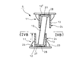
- FIG. 4B is a plan view of FIG. 4A viewed from the IVB-IVB direction. It is a front view which shows the modification of the seismic isolation structure of FIG.
- FIG. 5B is a plan view of FIG. 5A viewed from the VB-VB direction. It is a front view which shows the seismic isolation structure of Example 3 of this invention. It is a front view which shows the modification of FIG. It is a front view which shows the seismic isolation structure of Example 4 of this invention. It is a front view which shows the modification of FIG. It is explanatory drawing at the time of providing the example of the structure to which the seismic isolation structure of this invention is applied, and also providing the seismic isolation structure between the two members which are the pillars of a structure. It is explanatory drawing at the time of providing a seismic isolation structure between the two members which are the beams of a structure.
- FIG. 9a It is a front view of the three-dimensional warehouse which is an example of the structure to which the seismic isolation structure of this invention is applied. It is a side view of the three-dimensional warehouse of FIG. 9a. It is explanatory drawing for demonstrating the effect
- the three-dimensional warehouse 100 has a configuration in which a plurality of racks 3 (shelves) are three-dimensionally assembled by including a plurality of steel pillars 1 and a plurality of steel beams 2.
- the three-dimensional warehouse 100 is erected with the stacker crane 4 interposed therebetween, and the three-dimensional warehouse 100 has a length extending along the traveling direction of the stacker crane 4 and is orthogonal to the traveling direction of the stacker crane 4.
- the plurality of pillars 1 constituting the three-dimensional warehouse 100 have high strength to support the weight of the load stored in the rack 3.
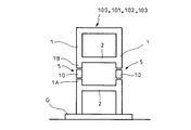
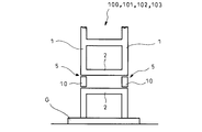
- the seismic isolation structure 5 of the present invention is provided for each of the plurality of pillars 1 constituting the three-dimensional warehouse 100 shown in FIGS. 9a and 9b.
- the seismic isolation structure 5 is provided at the same height position of each pillar 1 provided in the three-dimensional warehouse 100 as shown in FIGS. 9a and 9b.
- the seismic isolation structure 5 has a height position of about 1/3 to 1/2 from the upper side of the three-dimensional warehouse 100 in order to prevent the upper side of the three-dimensional warehouse 100 from locking. Is installed. Thus, even if the seismic isolation structure 5 is installed in the upper part of the three-dimensional warehouse 100, the seismic isolation structure 5 reduces the upper side of the seismic isolation structure 5, and as a result, the seismic isolation structure 5 does not. The inventor's research has revealed that the shaking of the lower structure is also reduced.
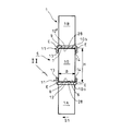
- the pillar 1 constituting the three-dimensional warehouse 100 includes a lower pillar member 1A (first member) having a plate-like member 12 at the upper end and a plate-like member 12 ′ at the lower end.
- the upper column member 1B (second member) is provided, and the two column members 1A and 1B have opposite flat plate members 12 and 12 'having horizontal and flat end surfaces 6 and 7, respectively.
- a seismic isolation column 10 for isolating the column 1 of the three-dimensional warehouse 100 by tilting is disposed so as to freely tilt.
- the two column members 1A and 1B and the seismic isolation column 10 are hollow or solid square steel having a rectangular horizontal cross section.
- the two column members 1A and 1B and the seismic isolation column 10 are not limited to square steel materials, but may be H-type steel materials, I-type steel materials, Z-type steel materials, and cylindrical steel materials.
- the abutment surface 8 of the one end 10a of the seismic isolation column 10 and the abutment surface 9 of the other end 10b of the seismic isolation column 10 are the end surfaces 6 of the plate-like members 12 and 12 ′ provided in the two column members 1A and 1B. , 7, the two column members 1 ⁇ / b> A, 1 ⁇ / b> B and the seismic isolation column 10 are held in a straight line state.
- a trigger mechanism 11 is provided that is provided with a mechanism (stopper member) so as to exhibit a trigger function.
- the trigger mechanism 11 shown in FIGS. 1a and 1b includes flat end surfaces 6 and 7 provided on two column members 1A and 1B, and the flat end surfaces 6 and 7 disposed between the two column members 1A and 1B.
- the base isolation column 10 having flat contact surfaces 8 and 9 to be crimped to each other, and the one end 10a and the other end 10b of the base isolation column 10 from the two column members 1A and 1B through the plate members 12 and 12 '.
- the stopper member 13 which protruded so that the edge part which might be may be enclosed from a horizontal direction. Further, the stopper member 13 shown in FIGS. 1 a and 1 b is inclined so as to form a clearance 14 that is separated from the seismic isolation column 10 as it is separated from the plate-like members 12 and 12 ′.
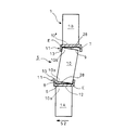
- the seismic isolation column 10 can tilt around the fulcrum E.
- the fulcrum E is formed by the horizontal and straight edges of the flat contact surfaces 8 and 9 of the seismic isolation column 10. .
- FIGS. 1a and 1b two column members 1A and 1B, a seismic isolation column 10 disposed between the two column members 1A and 1B, two column members 1A and 1B, and a seismic isolation column.
- the base isolation structure 5 is configured by a trigger mechanism 11 provided between the base 10 and the trigger mechanism 11.
- the seismic isolation structure 5 can be provided as a unit.
- the unitized seismic isolation structure 5 can be easily arranged by being incorporated in the middle of the column members 1A and 1B of the structure or between members such as the beams 2 and 2 constituting the structure. it can.
- the trigger mechanism 11 when the two column members 1 ⁇ / b> A and 1 ⁇ / b> B are relatively moved in the horizontal direction, the end edges of the end surfaces 6 and 7 of the seismic isolation column 10 come into contact with the inner surface of the stopper member 13. Thus, the seismic isolation column 10 is prevented from moving outward in the horizontal direction with respect to the two column members 1A and 1B. For this reason, the inner surface of the stopper member 13 and the end edges of the end surfaces 6 and 7 of the seismic isolation column 10 serve as fulcrums E, and the seismic isolation column 10 starts to tilt. In order to incline the seismic isolation column 10, as shown in FIGS.
- the plate-like members 12 and 12 ′ are separated from the inner surface of the stopper member 13 and the outer surface of the seismic isolation column 10. Therefore, instead of forming the clearance 14 that separates from the seismic isolation column 10, a predetermined clearance parallel to the outer surface of the seismic isolation column 10 may be provided between the seismic isolation column 10 and the stopper member 13.
- FIGS. 1 c and 1 d show another example of the trigger mechanism 11. Since the trigger mechanism 11 is arranged to have a vertically symmetrical shape, only the trigger mechanism 11 provided between the lower end of the seismic isolation column 10 and the lower column member 1A is shown in FIGS. 1c and d. Show.
- the trigger mechanism 11 of FIG. 1c forms a stopper member 13 composed of a protruding portion protruding from the plate member 12 so as to form a clearance 14 ′ parallel to the outer surface of the base isolation column 10, and the base isolation column.
- a convex portion 26 protrudes from the outer periphery of one end 10a (lower end) of the ten.
- the seismic isolation column 10 is prevented from moving in the horizontal direction when the convex portion 26 abuts against the stopper member 13, and the seismic isolation column 10 can start to tilt with the convex portion 26 as a fulcrum E. It has become.
- the convex portion 26 may be provided on the inner surface of the stopper member 13 near the upper surface of the plate-like member 12 provided on the column member 1A.
- a plurality of the convex portions 26 may be provided around the seismic isolation column 10 at intervals, or may be provided continuously in an annular shape around the seismic isolation column 10.
- the trigger mechanism 11 of FIG. 1d is a tension member that protrudes outward with respect to one end of the column member 1B when the stopper member 13 is provided so as to form a clearance 14 ′ parallel to the outer surface of the seismic isolation column 10.
- a protruding portion 10 '(flange portion) is provided. Accordingly, the seismic isolation column 10 is prevented from moving in the horizontal direction by the outer end of the overhanging portion 10 ′ coming into contact with the stopper member 13, and the seismic isolation column 10 is supported by the overhanging portion 10 ′.
- the inclination can be started with the outer end as a fulcrum E.
- FIG. 1c and 1d show the case where the stopper member 13 is provided so as to form a clearance 14 'parallel to the outer surface of the seismic isolation column 10, but as shown in FIG. You may incline so that a space
- a sheet-like elastic material 28 made of a thin rubber material or the like may be interposed between the end surfaces 6 and 7 of the plate-like members 12 and 12 'and the contact surfaces 8 and 9 of the seismic isolation column 10. Good.
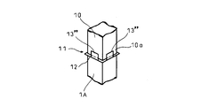
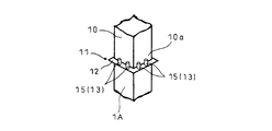
- FIGS. 2a to 2d show examples of the shape of the stopper member 13 constituting the trigger mechanism 11 provided between the two column members 1A and 1B and the seismic isolation column 10.
- FIG. Since the stopper member 13 constituting the trigger mechanism 11 provided on the two column members 1A and 1B has a vertically symmetrical shape, it is provided on the plate-like member 12 of the lower column member 1A in FIGS. 2a to 2d. Only the stopper member 13 is shown.
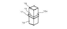
- FIG. 2a shows a case where a stopper member 13 protruding so as to surround the entire outer periphery of the one end 10a of the seismic isolation column 10 is provided as in FIG. 1a
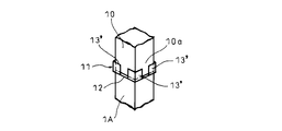
- FIG. FIG. 2c shows the case where the stopper member 13 ′ is provided only on the four corner portions of the plate-like member 12, and
- FIG. 2c shows the case where the stopper member 13 ′′ is provided only on the four side portions of the plate-like member 12. Shows the case.
- FIG. 2 d shows a case where the stopper member 13 by the protrusion 15 that is a stud member is provided so as to surround the outer periphery of the one end 10 a of the seismic isolation column 10 with respect to the plate-like member 12.
- the seismic isolation column 10 may be provided at one end 10a and the other end 10b. ⁇ Setting the width and depth of the seismic isolation column>
- the width or depth of the pillar 1 of the base isolation structure 5 is increased, it can be used to increase the trigger load of the base isolation structure 5 and increase the rigidity of the base isolation structure 5.
- FIG. 3a to 3d show the cross-sectional shape of the base isolation column 10, and the cross-sectional shape of the base isolation column 10 represents the shape of the contact surfaces 8 and 9 of the end portions 10a and 10b.
- FIG. 3a shows a case where the cross-sectional shape of the seismic isolation column 10 is a square in which the width B1 and the depth B2 are the same in the horizontal biaxial direction (X, Y), and FIG. This shows a case in which the cross-sectional shape is a rectangle with different widths B1 and B2 in the horizontal biaxial direction (X, Y).
- the cross-sectional shape of the seismic isolation column 10 may have a regular octagonal shape shown in FIG. 3c in which the four corners of the square in FIG.
- FIG. 3a are cut, or FIG. 3d in which the rectangular four corners in FIG. It may have an elongated octagonal shape as shown in FIG.
- the cross-sectional shape of the seismic isolation column 10 may be a polygon such as a hexagon other than the above shape, or may be a circle or an ellipse.
- FIG. 1a shows the column 1 in a stationary state, and the load applied to the upper column member 1B includes the flat end surface 7 of the column member 1B, the flat contact surface 9 of the seismic isolation column 10, and It is transmitted to the lower column member 1A through the flat contact surface 8 of the seismic isolation column 10 and the flat end surface 6 of the column member 1A, and the column 1 maintains a straight state.
- the end surface 7 of the column member 1B and the abutment surface 9 of the seismic isolation column 10 are abutted and pressed by the load applied to the column 1, and the abutment surface 8 of the seismic isolation column 10 and the end surface of the column member 1A. 6 is abutted and pressed.
- the column members 1A and 1B are provided with the stopper member 13 surrounding the outer periphery of the one end 10a and the other end 10b of the base isolation column 10, the base isolation column 10 is prevented from moving outward in the horizontal direction.
- the seismic isolation column 10 cannot be inclined due to the function, and the column 1 is held in a straight state.
- the trigger load magnitude at which 10 begins to tilt can be varied. When the width B1 and the depth B2 are set large, the trigger load at which the seismic isolation column 10 starts to tilt increases.
- the seismic isolation column 10 As the seismic isolation column 10 is tilted in this way, a large acceleration S2 in the horizontal and horizontal directions is isolated. Further, even when a large acceleration S2 shakes in the horizontal depth direction, the seismic isolation column 10 is similarly tilted in the depth direction so that the large acceleration S2 shake in the horizontal depth direction is isolated. At this time, if the size of the width in the left-right direction and the size in the depth direction of the contact surfaces 8 and 9 are set large, the seismic isolation column 10 becomes difficult to tilt in the left-right direction and depth direction, so a large trigger load is set. be able to. Thus, by providing the seismic isolation structure 5 with a simple configuration, it is possible to effectively isolate the vibration acting on the pillar 1 of the three-dimensional warehouse 100 (structure) in the horizontal biaxial direction.
- a stopper member 13 protruding from the plate-like member 12 provided on the two column members 1A and 1B so as to surround one end 10a and the other end 10b of the seismic isolation column 10 is provided. Since the trigger mechanism 11 that prevents the seismic column 10 from moving in the horizontal direction and starts the tilt of the seismic isolation column 10 by the fulcrum E is provided, the column 1 is horizontally placed by the trigger mechanism 11 having a simple configuration. It becomes possible to perform seismic isolation effectively in the biaxial direction.
- the trigger load at which the seismic isolation column 10 of the base isolation structure 5 starts to tilt can be set large by increasing the size B in the direction in which the base isolation structure 5 is not desired to be operated. That is, as shown in FIGS. 3a and 3c, when the cross-sectional shape of the seismic isolation column 10 is the same when the width B1 in the horizontal biaxial direction (X, Y) and the size B in the depth B2 are the same.
- the same trigger load can be set in the axial direction (X, Y). As shown in FIGS. 3b and 3d, when the cross-sectional shape of the seismic isolation column 10 is set such that the width B1 and the depth B2 in the horizontal biaxial directions (X, Y) are different from each other, the horizontal shape is horizontal.
- the trigger load in the biaxial direction (X, Y) can be set differently.
- the two column members 1A and 1B and the seismic isolation column 10 are held in a straight line by the contact between the flat end surfaces 6 and 7 and the flat contact surfaces 8 and 9. Furthermore, when the two column members 1A and 1B move relative to each other in the horizontal direction, the one end 10a and the other end 10b of the seismic isolation column 10 move outward in the horizontal direction with respect to the two column members 1A and 1B. Is prevented by the stopper member 13. For this reason, the seismic isolation column 10 comes to incline around the fulcrum E, whereby the structure can be effectively isolated in the horizontal biaxial direction by the seismic isolation structure 5 having a simple configuration. That is, seismic isolation is possible in all horizontal directions crossing the horizontal biaxial directions (X, Y).
- a sheet-like elastic material 28 formed of thin rubber or the like is installed between the end faces 6 and 7 of the plate-like members 12 and 12 ′ and the contact surfaces 8 and 9 of the seismic isolation column 10.
- the impact contact load between the shaped members 12, 12 ′ and the seismic isolation column 10 can be suppressed.
- the sheet-like elastic material 28 can use a foam material instead of a rubber material. In this case, the restoring force is smaller than that of the rubber material, but it can be expected to increase the effect of suppressing the contact load.
- FIGS. 4a and 4b show the seismic isolation structure of Example 2 of the present invention.
- the trigger mechanism 11 shown in FIGS. 4a and 4b is provided on a projecting portion 27 (flange portion) projecting outward from one end 10a and the other end 10b of the seismic isolation column 10 and the plate-like members 12 and 12 ′.
- the stopper member 13 having a required length surrounds the outer periphery of the protruding portion 27 with a clearance.
- the stopper member 13 shown in FIGS. 4a and 4b has a cylindrical shape with a rectangular cross section.
- Reference numeral 23 denotes a reinforcing bracket.
- the stopper member 13 forms a tilt angle limiting member 24 by having a protruding length J that contacts the seismic isolation column 10 at a position corresponding to the tilt angle at which the seismic isolation column 10 can return with its own weight. .
- FIGS. 5a and 5b show a seismic isolation structure which is a modification of FIG. 4a and FIG. 4b of the second embodiment.
- the trigger mechanism 11 shown in FIGS. 5a and 5b has a plate-like member 12, 12 ′ and a flange-like shape fixed to the plate-like member 12, 12 ′ and provided at one end 10a and the other end 10b of the seismic isolation column 10.
- a stopper member 13 having a required length protruding so as to surround the outer periphery of the overhanging portion 27.
- the stopper member 13 shown in FIGS. 5a and 5b is made of a steel material having a U-shaped cross section, and is arranged symmetrically so as to sandwich the protruding portion 27 from the front and rear and from the left and right.
- the stopper member 13 has a web surface that is close to the overhanging portion 27 at a fixed portion with respect to the plate-like members 12 and 12 ′.
- An inclined surface 25 is formed so as to increase the interval of.
- the stopper member 13 forms a tilt angle limiting member 24 by having a protruding length J that contacts the seismic isolation column 10 at a position corresponding to the tilt angle at which the seismic isolation column 10 can return with its own weight. .
- the tilt angle limiting member 24 having the protruding length J is constituted by the stopper member 13
- the seismic isolation column is formed by the tilt angle limiting member 24. It can restrict
- the plate-like members 12, 12 ′, the stopper member 13 provided on the plate-like members 12, 12 ′, and the seismic isolation column 10 are provided.
- the seismic isolation structure 5 including the trigger mechanism 11 can be unitized independently from the structure to be seismically isolated, and the unitized seismic isolation structure 5 includes the column members 1A and 1B of the structure, It can be easily assembled and arranged in the beam 2 or the like.
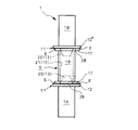
- FIGS. 6a and 6b show another embodiment of the seismic isolation structure 5 provided in the pillar 1 constituting the three-dimensional warehouse 100.
- the seismic isolation structure 5 shown in FIGS. 6a and 6b includes a convex portion 20 provided at the center of one of the end surfaces 6 and 7 of the two column members 1A and 1B and the contact surfaces 8 and 9 of the seismic isolation column 10;
- a stopper member 13 is provided that includes end surfaces 6 and 7 of the two column members 1A and 1B and a recess 21 provided at the other center of the contact surfaces 8 and 9 of the seismic isolation column 10 so as to be fitted to the convex portion 20.
- the trigger mechanism 11 is configured. In FIG.
- a convex portion 20 is provided on the contact flange 17 of the seismic isolation column 10, and the convex portion 20 is fitted in a concave portion 21 formed by column members 1A and 1B made of square pipes.
- the convex portion 20 and the concave portion 21 may have a truncated pyramid shape or a truncated cone shape.
- FIG. 6b the case where the convex part 20 is provided in the plate-like members 12 and 12 'of the column members 1A and 1B and the concave part 21 is provided in the seismic isolation column 10 is shown.
- the convex portion 20 and the concave portion 21 of the trigger mechanism 11 also serve as an alignment mechanism.
- the plate members 12 and 12 ′ of the column members 1A and 1B have a shape protruding outward with respect to the contact flange 17 of the seismic isolation column 10.
- a fulcrum E where the seismic isolation column 10 starts to tilt is formed around the plate-like members 12 and 12 ′ of the column members 1A and 1B.
- 6A and 6B show the case where the plate-like members 12 and 12 ′ protrude outward from the contact flange 17 and the fulcrum E is formed by the outer periphery of the contact flange 17.
- the contact flange 17 may protrude outward
- the fulcrum E may be formed by the outer periphery of the plate-like members 12, 12 ′.
- the configuration of the seismic isolation structure 5 can be simplified. Further, since the fulcrum E can be arbitrarily extended outward from the seismic isolation column 10 by the contact flange 17 and the plate-like members 12, 12 ', the seismic isolation column 10 starts to tilt with a simple configuration. The trigger load can be increased.
- the convex portion 20 and the concave portion 21 also serve as an alignment mechanism, there is a displacement in the horizontal direction between the two column members 1A, 1B and the seismic isolation column 10. Even in this case, when the tilted seismic isolation column 10 is restored, the two column members 1A and 1B and the seismic isolation column 10 are adjusted to a certain position and restored.
- the alignment mechanism including the convex portion 20 and the concave portion 21 shown in FIGS. 6a and 6b can be applied to other embodiments.
- FIGS. 7 a and 7 b show another embodiment of the seismic isolation structure 5 provided for the pillar 1 constituting the three-dimensional warehouse 100.
- the seismic isolation structure 5 shown in FIGS. 7a and 7b has plate-like members 12 and 12 provided at the upper end of the lower column member 1A and the lower end of the upper column member 1B in the same configuration as in FIGS. 6a and 6b.
- the trigger addition member that elastically connects the end surfaces 6 and 7 of the two column members 1 ⁇ / b> A and 1 ⁇ / b> B and the contact surfaces 8 and 9 of the seismic isolation column 10 in close contact with each other.
- a trigger mechanism 11 having 18 is configured.
- the trigger adding member 18 may include a restoring spring 19 (elastic body) such as a disc spring shown in the figure.
- a restoring spring that attracts the end surfaces 6 and 7 of the two column members 1A and 1B and the contact surfaces 8 and 9 of the seismic isolation column 10 in close contact with each other. 19 is provided, the trigger load at which the seismic isolation column 10 starts to tilt around the fulcrum E is increased as compared with the cases of FIGS. 1a to 1d, 6a and 6b. Become. Furthermore, the trigger load can be adjusted by selecting the pulling strength of the restoring spring 19. Moreover, the natural period when the seismic isolation column 10 tilts can be adjusted by selecting the attractive strength of the restoring spring 19. ⁇ About trigger acceleration setting>
- the corresponding trigger acceleration ⁇ can be set larger as the width B1 and the depth B2 of the cross-sectional area of the pillar 1 constituting the seismic isolation structure 5 are larger.
- the trigger acceleration ⁇ that can be handled in the depth direction can be set large.
- the natural frequency F (Hz) of the seismic isolation structure 5 having the trigger mechanism 11 having the restoring spring 19 is given by the following equation.
- k O coefficient of the restoring spring B: width of the contact surfaces 8 and 9 of the contact flange 17
- L distance between the restoring springs 19
- H height of the seismic isolation column 10: number of columns 1 M: Mass above the seismic device
- both the natural frequencies in the horizontal biaxial direction (X, Y) are increased.
- the size B of the contact surfaces 8 and 9 of the contact flange 17 provided in the seismic isolation column 10 can be set separately in the horizontal biaxial direction, it is desired to increase or decrease the rigidity of the seismic isolation structure 5.
- the natural frequency can be arbitrarily set by adjusting the magnitude B of the direction.
- the restoring spring 19 has a trigger function based on the width B1 and the depth B2 of the contact surfaces 8, 9 of the contact flange 17 provided in the seismic isolation column 10.
- the trigger load when the seismic isolation column 10 starts to tilt can be set to a large value.
- the deformation at the time of the occurrence of an earthquake is considered to be large.
- the width B1 and the depth B2 of the contact surfaces 8, 9 of the contact flange 17 provided in the base isolation column 10 are increased to increase the rigidity of the base isolation structure 5.
- the seismic isolation structure 5 of the present invention includes the three-dimensional warehouse 100, the boiler equipment 101, the three-dimensional parking equipment 102, the crane, and the unloader shown in FIGS. 9a and 9b.
- the present invention can be applied to the pillar 1 constituting a structure such as a cargo handling facility 103 such as a conveyor device.
- the seismic isolation structure 5 can be provided in the middle of the pillar 1 constituting the structure, or can be provided between the lower end of the pillar 1 and the foundation G.
- the said seismic isolation structure 5 can be provided between the members which consist of the beams 2 and 2 which comprise a structure, as shown in FIG. 8b.
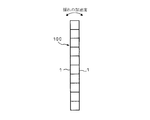
- FIG. 10a shows a three-dimensional warehouse 100 that does not include the seismic isolation structure 5
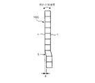
- FIG. 10b shows a case of the three-dimensional warehouse 100 that includes one stage of the base isolation structure 5
- FIG. 10c includes a two-stage seismic isolation structure 5.
- the case of the three-dimensional warehouse 100 is shown in comparison.
- FIG. 10a in the three-dimensional warehouse 100 without the seismic isolation structure 5, when the foundation is shaken due to the earthquake, the vibration transmitted to the three-dimensional warehouse 100 becomes a larger acceleration toward the upper part, and the upper end is extremely shaken. Become bigger.
- the deformation amount ⁇ can be absorbed by the seismic isolation function of the seismic isolation structure 5, so Therefore, the shaking of the upper part of the three-dimensional warehouse 100 is reduced.
- FIG. 10c in the three-dimensional warehouse 100 in which the pillar 1 is provided with the upper and lower two-stage seismic isolation structure 5, the deformation up to the deformation amount 2 ⁇ is eliminated by the seismic isolation action of the two-stage seismic isolation structure 5. Since it can be tolerated as a seismic device, it can be used as a seismic isolation device even for large-scale earthquakes with greater shaking. Therefore, even if the seismic isolation structure 5 has a small seismic isolation function, by providing the seismic isolation structure 5 in multiple stages, as shown in FIG. can do.
- the seismic isolation structure of the present invention is not limited to the above-described embodiments, and it is needless to say that various modifications can be made without departing from the gist of the present invention.
Landscapes
- Engineering & Computer Science (AREA)
- Architecture (AREA)
- Business, Economics & Management (AREA)
- Emergency Management (AREA)
- Environmental & Geological Engineering (AREA)
- Civil Engineering (AREA)
- Structural Engineering (AREA)
- Buildings Adapted To Withstand Abnormal External Influences (AREA)
- Vibration Prevention Devices (AREA)
- Warehouses Or Storage Devices (AREA)
Abstract
Description
二つの前記部材と前記免震柱の少なくとも一方に設けられ、二つの前記部材が水平方向へ相対移動した際に前記免震柱が水平方向へ移動するのを防止し、前記端面と前記当接面が圧着した状態から前記免震柱が傾きを開始する支点を形成するようにしたストッパ部材とを有し、
二つの前記部材の平坦な前記端面及び該端面に圧着される前記免震柱の平坦な前記当接面と、前記支点を形成する前記ストッパ部材とによりトリガ機構を構成した
ことを特徴とする。
<免震柱の幅と奥行きの設定について>
<トリガ加速度設定について>

H:免震柱10の高さ
N:柱1の数
M:免震装置より上部の質量
g:重力加速度
fO:復元ばねに与えた初期荷重
B:柱の幅B1及び奥行きB2の大きさ

<免震構造の剛性の増大>

B:当接フランジ17の当接面8,9の幅の大きさ
L:復元ばね19の間隔
H:免震柱10の高さ
N:柱1の数
M:免震装置より上部の質量
1B 柱部材(第二の部材)
2 梁(部材)
5 免震構造
6 端面
7 端面
8 当接面
9 当接面
10 免震柱
10a 一端
10b 他端
11 トリガ機構
12 板状部材
12' 板状部材
13 ストッパ部材
13' ストッパ部材
13'' ストッパ部材
15 突起(突出部)
18 トリガ付加部材
19 復元ばね(弾性体)
20 凸部(ストッパ部材)
21 凹部(ストッパ部材)
24 傾斜角制限部材
E 支点
100 立体倉庫
101 ボイラ設備
102 立体駐車設備
103 荷役設備
Claims (12)
- 平坦な端面が対向する二つの部材の間に配置され、平坦な前記端面に圧着される平坦な当接面を一端と他端に形成して前記当接面が前記端面に圧着した状態から傾斜が可能な免震柱と、
二つの前記部材と前記免震柱の少なくとも一方に設けられ、二つの前記部材が水平方向へ相対移動した際に前記免震柱が水平方向へ移動するのを防止し、前記端面と前記当接面が圧着した状態から前記免震柱が傾きを開始する支点を形成するようにしたストッパ部材とを有し、
二つの前記部材の平坦な前記端面及び該端面に圧着される前記免震柱の平坦な前記当接面と、前記支点を形成する前記ストッパ部材とによりトリガ機構を構成した
ことを特徴とする免震構造。 - 二つの前記部材は柱部材であることを特徴とする請求項1に記載の免震構造。
- 二つの前記部材は梁であることを特徴とする請求項1に記載の免震構造。
- 前記支点は、二つの前記部材の平坦な前記端面の端縁又は前記免震柱の平坦な前記当接面の端縁によって形成されることを特徴とする請求項1に記載の免震構造。
- 前記ストッパ部材は、二つの前記部材と前記免震柱の一方に、二つの前記部材と前記免震柱の他方の端部を水平方向から囲むように突出した突出部であることを特徴とする請求項1に記載の免震構造。
- 前記ストッパ部材は、前記免震柱が自重で復帰できる傾斜角度に対応した位置で前記免震柱又は二つの前記部材に接する突出長さの突出部を備えて傾斜角制限部材を形成したことを特徴とする請求項5に記載の免震構造。
- 前記ストッパ部材は、二つの前記部材と前記免震柱の一方の中心に設けた凸部と、該凸部と嵌合するように二つの前記部材と前記免震柱の他方の中心に設けた凹部を有することを特徴とする請求項1に記載の免震構造。
- 前記トリガ機構は、二つの前記部材と前記免震柱を弾力的に連結して前記免震柱が傾きを開始するトリガ荷重を調節できる弾性体を有することを特徴とする請求項1に記載の免震構造。
- 二つの前記部材の平坦な前記端面と前記免震柱の平坦な前記当接面は、水平二軸方向における幅と奥行きの大きさが異なっていることを特徴とする請求項1に記載の免震構造。
- 二つの前記部材と前記免震柱との間に形成する前記支点が、二つの前記部材及び前記免震柱の水平方向外側へ張り出した位置に設けられ、前記免震柱が傾きを開始するトリガ荷重を増加させたことを特徴とする請求項1に記載の免震構造。
- 前記請求項1~10のいずれか1つに記載の免震構造を備えたことを特徴とする構造物。
- 免震構造を備えた立体倉庫であることを特徴とする請求項11に記載の構造物。
Priority Applications (2)
| Application Number | Priority Date | Filing Date | Title |
|---|---|---|---|
| CN201480046207.0A CN105452576B (zh) | 2013-08-19 | 2014-08-18 | 免震构造 |
| JP2015532851A JP6168151B2 (ja) | 2013-08-19 | 2014-08-18 | 免震構造 |
Applications Claiming Priority (2)
| Application Number | Priority Date | Filing Date | Title |
|---|---|---|---|
| JP2013-169827 | 2013-08-19 | ||
| JP2013169827 | 2013-08-19 |
Publications (1)
| Publication Number | Publication Date |
|---|---|
| WO2015025820A1 true WO2015025820A1 (ja) | 2015-02-26 |
Family
ID=52483595
Family Applications (1)
| Application Number | Title | Priority Date | Filing Date |
|---|---|---|---|
| PCT/JP2014/071579 Ceased WO2015025820A1 (ja) | 2013-08-19 | 2014-08-18 | 免震構造 |
Country Status (4)
| Country | Link |
|---|---|
| JP (1) | JP6168151B2 (ja) |
| CN (1) | CN105452576B (ja) |
| TW (1) | TWI577859B (ja) |
| WO (1) | WO2015025820A1 (ja) |
Cited By (1)
| Publication number | Priority date | Publication date | Assignee | Title |
|---|---|---|---|---|
| JP2017154852A (ja) * | 2016-03-01 | 2017-09-07 | 株式会社Ihi | 免震装置 |
Families Citing this family (2)
| Publication number | Priority date | Publication date | Assignee | Title |
|---|---|---|---|---|
| JP6790618B2 (ja) * | 2016-09-07 | 2020-11-25 | 村田機械株式会社 | 免震装置 |
| KR102610698B1 (ko) * | 2018-12-14 | 2023-12-05 | 민성준 | 개보수가 용이한 면진 데크로드 |
Citations (3)
| Publication number | Priority date | Publication date | Assignee | Title |
|---|---|---|---|---|
| JPS6458733A (en) * | 1987-08-28 | 1989-03-06 | Tetsuo Kuroiwa | Structure form aiming at earthquakeproofing and related device |
| JP2003004097A (ja) * | 2001-06-19 | 2003-01-08 | Ishikawajima Harima Heavy Ind Co Ltd | 鋼構造物の水平2軸免震装置 |
| JP2011043031A (ja) * | 2009-08-24 | 2011-03-03 | Takenaka Komuten Co Ltd | 免震構造、及び免震構造物 |
Family Cites Families (3)
| Publication number | Priority date | Publication date | Assignee | Title |
|---|---|---|---|---|
| JP2004092080A (ja) * | 2002-08-29 | 2004-03-25 | Shimizu Corp | 鉄骨架構、その構築方法、および制震構造 |
| CN201972240U (zh) * | 2010-12-28 | 2011-09-14 | 陈云 | 自复位摇摆隔震支座 |
| CN202170577U (zh) * | 2011-06-10 | 2012-03-21 | 广州大学 | 一种高层建筑的隔震结构 |
-
2014
- 2014-08-18 WO PCT/JP2014/071579 patent/WO2015025820A1/ja not_active Ceased
- 2014-08-18 CN CN201480046207.0A patent/CN105452576B/zh active Active
- 2014-08-18 JP JP2015532851A patent/JP6168151B2/ja active Active
- 2014-08-19 TW TW103128446A patent/TWI577859B/zh active
Patent Citations (3)
| Publication number | Priority date | Publication date | Assignee | Title |
|---|---|---|---|---|
| JPS6458733A (en) * | 1987-08-28 | 1989-03-06 | Tetsuo Kuroiwa | Structure form aiming at earthquakeproofing and related device |
| JP2003004097A (ja) * | 2001-06-19 | 2003-01-08 | Ishikawajima Harima Heavy Ind Co Ltd | 鋼構造物の水平2軸免震装置 |
| JP2011043031A (ja) * | 2009-08-24 | 2011-03-03 | Takenaka Komuten Co Ltd | 免震構造、及び免震構造物 |
Cited By (1)
| Publication number | Priority date | Publication date | Assignee | Title |
|---|---|---|---|---|
| JP2017154852A (ja) * | 2016-03-01 | 2017-09-07 | 株式会社Ihi | 免震装置 |
Also Published As
| Publication number | Publication date |
|---|---|
| TW201529942A (zh) | 2015-08-01 |
| CN105452576B (zh) | 2017-05-10 |
| JPWO2015025820A1 (ja) | 2017-03-02 |
| TWI577859B (zh) | 2017-04-11 |
| CN105452576A (zh) | 2016-03-30 |
| JP6168151B2 (ja) | 2017-07-26 |
Similar Documents
| Publication | Publication Date | Title |
|---|---|---|
| JPH0374304B2 (ja) | ||
| JP2015224482A (ja) | 免震構造 | |
| JP6168151B2 (ja) | 免震構造 | |
| JP6107955B2 (ja) | 構造物を構成する柱の免震構造及び構造物 | |
| JP6398281B2 (ja) | 免震構造 | |
| JP6753072B2 (ja) | 免震装置 | |
| JP4812463B2 (ja) | 免震床構造 | |
| JP6414271B2 (ja) | 構造物を構成する柱の免震構造 | |
| JP6232803B2 (ja) | 構造物を構成する柱の免震構造 | |
| JP6716946B2 (ja) | 免震装置 | |
| JP6248454B2 (ja) | 自動倉庫 | |
| JP6662104B2 (ja) | 免震装置 | |
| JP2015205751A (ja) | 免震構造 | |
| KR101267134B1 (ko) | 면진 장치 | |
| JP6398269B2 (ja) | 免震構造 | |
| JP2016079655A (ja) | 免震構造 | |
| JP6303736B2 (ja) | 免震構造及び該免震構造を備えた免震装置 | |
| JP6123546B2 (ja) | 構造物を構成する柱の免震構造 | |
| JP2015218468A (ja) | 免震構造 | |
| JP3138538U (ja) | 耐震用台座とその誤作動防止用段差付楔体 | |
| JP2015028250A (ja) | 構造物を構成する柱の免震構造 | |
| JP2015197016A (ja) | 免震構造 | |
| JP7272850B2 (ja) | 滑り免震機構 | |
| JP2015209322A (ja) | 免震構造 | |
| JP6748930B2 (ja) | 免震機構 |
Legal Events
| Date | Code | Title | Description |
|---|---|---|---|
| WWE | Wipo information: entry into national phase |
Ref document number: 201480046207.0 Country of ref document: CN |
|
| 121 | Ep: the epo has been informed by wipo that ep was designated in this application |
Ref document number: 14837457 Country of ref document: EP Kind code of ref document: A1 |
|
| ENP | Entry into the national phase |
Ref document number: 2015532851 Country of ref document: JP Kind code of ref document: A |
|
| NENP | Non-entry into the national phase |
Ref country code: DE |
|
| 122 | Ep: pct application non-entry in european phase |
Ref document number: 14837457 Country of ref document: EP Kind code of ref document: A1 |